EP4152727B1 - Verfahren zur optimierung einer nutzungsverteilung in einem kommunikationsnetz - Google Patents
Verfahren zur optimierung einer nutzungsverteilung in einem kommunikationsnetz Download PDFInfo
- Publication number
- EP4152727B1 EP4152727B1 EP21205005.8A EP21205005A EP4152727B1 EP 4152727 B1 EP4152727 B1 EP 4152727B1 EP 21205005 A EP21205005 A EP 21205005A EP 4152727 B1 EP4152727 B1 EP 4152727B1
- Authority
- EP
- European Patent Office
- Prior art keywords
- sub
- path
- demands
- demand
- network
- Prior art date
- Legal status (The legal status is an assumption and is not a legal conclusion. Google has not performed a legal analysis and makes no representation as to the accuracy of the status listed.)
- Active
Links
Images


Classifications
-
- H—ELECTRICITY
- H04—ELECTRIC COMMUNICATION TECHNIQUE
- H04L—TRANSMISSION OF DIGITAL INFORMATION, e.g. TELEGRAPHIC COMMUNICATION
- H04L45/00—Routing or path finding of packets in data switching networks
- H04L45/12—Shortest path evaluation
- H04L45/125—Shortest path evaluation based on throughput or bandwidth
Definitions
- the invention pertains to a computer-implemented method for optimizing a usage distribution in a communications network in which data traffic is routed, wherein the communications network has a plurality of communication nodes which are connectable over edges (links) of communication paths for a routing of the data traffic.
- the invention also pertains to a quantum concept processor configured for performing such a method, a computer program implemented to perform such a method, a system for a network planner and an interface arrangement.
- link weights are often related to link capacities, i.e., the maximum amount of data per unit time that can be routed over a link from a starting node to an end node connected by that link respectively edge.
- link capacities i.e., the maximum amount of data per unit time that can be routed over a link from a starting node to an end node connected by that link respectively edge.
- link metrics i.e., the maximum amount of data per unit time that can be routed over a link from a starting node to an end node connected by that link respectively edge.
- IGP Interior Gateway Protocols
- linear optimization techniques applied so far quickly reach their limits when actual non-linear conditions are taken into account, like redundancies, geographical subgroups or subdomains (e.g. European network and US network considered in one model), inclusion of satellites, Quality of Service, QoS, relationships, etc.
- known techniques often lead to the problem of unused capacity usage and overloads of link capacities in communication paths within a network, where many links are close to their capacity limit.
- US 2020/396154 A1 discloses methods, apparatus and computer programs for allocating traffic in a telecommunications network comprising a plurality of nodes, with pairs of nodes being connected by respective links.
- a method comprises obtaining a plurality of demands for connectivity between respective first nodes and respective second nodes of the telecommunications network, each demand being subject to a respective constraint associated with the connectivity between the respective first node and the respective second node; for each demand, generating a list of possible paths between the first node and the second node satisfying the constraint; based on the list of possible paths for each demand and an indication of traffic usage for each demand, determining, for each demand, weights in respect of each of the possible paths; and providing the weights to nodes of the telecommunications network, for the distribution of traffic associated with each of the plurality of demands to the possible paths in accordance with the respective weights.
- US 2017/286852 A1 discloses a method for determining a minimum connected dominating set in a graph, the method comprising obtaining an indication of an input graph, the input graph comprising a plurality of nodes and a plurality of edges; generating a distance table comprising for each node of the input graph, an indication of a distance between the given node and each of the other node of the plurality of nodes; generating a corresponding constrained binary quadratic programming problem using the generated distance table; providing the corresponding constrained binary quadratic programming problem to a quantum annealing solver; obtaining at least one approximate solution from the quantum annealing solver; post-processing the at least one approximate solution and providing the post-processed at least one approximate solution.
- the problem of the present disclosure lies in providing enhanced techniques that allow for an optimized utilization of communication paths within a communications network with respect to capacity limits, thereby achieving an optimized routing.
- the method is a computer-implemented procedure for optimizing a usage distribution in a communications network in which data traffic is routed, wherein the communications network has a plurality of communication nodes.
- the communication nodes are connected by edges of the communications network.
- a series of edges yields a communication path for a routing of the data traffic.
- an edge of a communication path in this context describes a connection between two adjacent nodes within a communication path.
- the method comprises the following steps:
- This method reliably tackles the problem of routing network demands in a communications network along optimized communication paths such that the overall capacity in the network is optimally used, thereby avoiding that link capacities in the network are exceeded.
- one optimal option for a communication path from the set of optional communication paths can be selected.
- the selection is chosen such that the capacity of all edges (links) in used communication paths within the network is respected as upper limit for the total volume of traffic demands routed along them and that the average load of all communication paths within a network is minimum. Further, a minimization of a maximum link utilization (MLU) can be achieved.
- MLU maximum link utilization
- Traffic demands in this context are modelled as 3-tuples, defining an origin node (source of a data stream), an end node or destination node (destination of a data stream), and the determined data traffic to be transferred between origin and destination.
- the focus is on providing continuous data streams over the network, which are to be modelled and routed in such a way that no data is lost during transmission by exceeding specified capacities on given transport links. Measurement for data transfer rates of such data stream requests or demands are currently specified in Gbps (Gigabit per second).
- Sub-demands in this context are traffic demands split into fragments. Hence, one sub-demand represents a fragment of an initial traffic demand in terms of the data volume split into a determined data volume packet.
- the optional communication paths in this context are in general not subject to any restrictions with regard to routing, path length or number of intermediary nodes in the network.
- the set of optional communication paths is pre-determined regarding each sub-demand that is to be transmitted through the network. In such a pre-determination useful or suitable paths can be considered in terms of latency (shortest possible paths, fewest possible IP hops), redundancy (the model should be redundant against failure of a connection), Domains (e.g. EU, US) or hierarchies (core network, access networks), etc.
- the set of optional communication paths is a subset of possible communication paths for each traffic demand or for each respective sub-demand.
- the set of optional communication paths is for example stored as "path box" which can be accessed by the computer-implemented algorithm.
- the path box As many divergent (most diverse or disjoint) paths as suitable are pre-selected in the path box to provide a sufficiently large solution space for solving the quadratic stress function, i.e. finding a (global) minimum, by the quantum concept processor.
- Such pre-selection can depend on the processing performance and capacity of the quantum concept processor.
- traffic demands in this context can theoretically be split into sub-demands with any even or uneven fragment size that is suitable for the practical implementation.
- the approach here is to split each traffic demands into a plurality of sub-demands and to find for each sub-demand an optimal communication path through the network.
- MCFR Multi Commodity Flow Routing
- Such splitting of the traffic demands can depend on the processing performance and capacity of the quantum concept processor.
- a quadratic optimization problem By calculating, for each sub-demand, fractional capacity usages of the edges within the set of optional communication paths and formulating the calculated fractional capacity usages as terms of a quadratic stress function, a quadratic optimization problem can be formulated in order to deal with the complexity of the above-explained optimization problem.
- the application of such quadratic optimization problem has the effect that a quadratic stress function can be formulated which heavily penalizes a high capacity usage on individual edges of communication paths.
- the minimum of the quadratic stress function preferably is a global minimum, but can also be a local minimum.
- the method hence, has the technical effect and advantage of a uniformly minimal utilization of the network and distribution of the distance to the capacity limits within the network in order to achieve a uniformly minimal utilization of the network with respect to its capacity limits.
- the underlying quadratic optimization problem is very complex. This is not only due to a potential impact of one selected communication path to other communication paths and a vast amount of data traffic to be managed between a plurality of origin nodes and destination nodes in the network.
- the problem is also very complex because there are many practical constraints that have to be taken into account. As more constraints are implemented, such problems become more complex and difficult to solve.
- the herein described method advantageously shows its strength compared to conventional approaches more and more, the more complex the underlying problem is. In other words, for a complex optimization problem taking into consideration practical constraints as explained above, the herein described method has a significant strength over conventional techniques.
- the herein described method makes use of an approach inspired by quantum computing.
- the calculation of optimized solutions of the quadratic stress function for determining optimized communication paths for all sub-demands of the set of traffic demands is performed by a so-called quantum concept processor.
- a quantum concept processor in the context of the present disclosure a processor is defined that solves a so called "Ising model" or the equivalent quadratic unconstrained binary problem.
- this is a processor configured to solve an optimization problem by means of quantum annealing or quantum annealing emulation.
- Such a processor is for example based on conventional hardware technology, for example based on complementary metal-oxide-semiconductor (CMOS) technology.
- CMOS complementary metal-oxide-semiconductor
- An example of such quantum concept processor is Fujitsu's digital annealer.
- any other quantum processors can be used for the herein described method, in future times also such technologies that are based on real quantum bit technologies.
- Further examples of such quantum concept processors are the quantum annealer of DWave (e.g. 5000Q), but also quantum gate computers (IBM, Rigetti, OpenSuperQ, IonQ or Honeywell) making use of quantum optimisation algorithms like QAOA or VQE.
- a quantum concept processor as defined herein is a processor which realises the concept of minimization of a so-called quadratic unconstrained binary optimization (QUBO) function, either on a special processor classic technology, a quantum gate computer or on a quantum annealer.
- QUBO quadratic unconstrained binary optimization
- the method further comprises the following steps:
- the path terms are calculated under consideration of a path condition that each sub-demand is routed along exactly one communication path from the set of optional communication paths.
- Such path condition forms a constraint or "boundary" for the method such that each sub-demand can only be assigned to exactly one path out of the path box. This avoids undesirable solutions and guarantees that a routing of each sub-demand is sufficiently considered.
- the traffic demands are split into sub-demands with determined discrete data volumes.
- the sub-demands can each have an equal size or different sizes, depending on the implementation and practical considerations. For example, a traffic demand with a volume size of 1000 Gbit/s is split into a plurality of sub-demands with even sizes of 50 Gbit/s. Alternatively, sub-demands with different sizes are generated, wherein different sub-demands may have for example different sizes of 50, 100, and 250 Gbit/s.
- a splitting of the traffic demands into sub-demands with determined discrete data volumes has the effect of a practically implementable algorithmic procedure within the network and helps keeping control of stable and reliable data streams. In this way, such approach is a kind of discrete MCFR approach.
- the quadratic stress function is formulated under consideration of one or both of the following constraints for the set of traffic demands or for the respective sub-demands:
- solutions of the optimization problem can be penalized that contravene the above conditions. This enables finding suitable optimized solutions considering practical constraints of the actual network conditions of the communications network.
- the set of optional communication paths for an individual routing of each sub-demand is specified under consideration of one or more of the following constraints:
- the set of optional communication paths for an individual routing of each sub-demand is specified such that for topologically near origin and destination nodes a smaller number of optional communications paths is selected than for topologically distant origin and destination nodes.
- the quadratic stress function is formulated as a quadratic unconstrained binary optimization (QUBO) function.
- QUBO quadratic unconstrained binary optimization
- This QUBO function serves as "input" for the quantum concept processor that solves this optimization problem for an optimized routing of all sub-demands according to the above-explained method.
- QUBOs are quadratic order polynomials in binary variables which are represented in a quantum concept processor as bits or quantum bits (Q-bits hereinafter).
- the QUBO function represents the sum of potential contributions of the fractional capacity usages of respective edges within optional communication paths as a function of different Q-bits, wherein each Q-bit represents the selection of a path alternative that can assume the value "0" or the value "1".
- the quantum concept processor runs through different settings of the different Q-bits in order to find such solution(s) that minimize the quadratic optimization problem.
- a QUBO representation of the optimization problem has elegant properties regarding the here applied quantum concept computing. For example, the above explained path variables are formulated in the form of such Q-bits.
- the quadratic stress function and the path condition are combined into a global QUBO function.
- the global QUBO function one or more of the above-explained constraints can be considered.
- one or more of the above-explained constraints can be weighted within the QUBO function as soft constraints. This has the advantage that the QUBO function can be somewhat fine-tuned depending on the focus of the optimization problem either on the optimization of the uniform capacity usage distribution throughout the network or on the fulfilment of one or more of the mentioned (soft) constraints.
- the above-mentioned problem is also solved by a quantum concept processor as claimed in the enclosed claims.
- the quantum concept processor is configured for performing one or more steps of a method as described above.
- the quantum concept processor is a digital annealing processing unit. This unit can be specially configured to perform quantum annealing or a quantum annealing emulation as explained above.
- the quantum concept processor can be of any type explained above.
- a computer program comprising instructions that, when the program is executed by one or more processors, cause each of the one or more processors to perform one or more steps of a method as described above.
- processors e.g. a quantum concept processor as explained above.
- Other processors can be configured for processing, by executing the computer program, preparatory or iterative steps of or for a method as explained above.
- a workplace for a network planner, configured for verifying an optimized routing determined by a method as described above.
- a workplace for example, has verification means that are configured for an (automated or semi-automated) verification of an optimized routing determined by a method as described above.
- This serves a network planner to verify optimization results found by a method as described above.
- the verification means can be implemented in software and/or hardware.
- the workplace can communicate or be connected to a system comprising a quantum concept processor that performs the method as described above. The results can then be taken over into the workplace.
- an interface arrangement comprising one or more interfaces to a plurality of communication nodes of a communications network in which data traffic is routed, wherein the interface arrangement is configured to automatically deploy an optimized routing determined by a method as described above to the communication nodes of the communications network.
- an optimized routing determined by a method as described above can be (automatically or semi-automatically) be deployed to a plurality of communication nodes of a respective communications network.
- the interface arrangement can communicate or be connected to a workplace as describe above or to a system comprising a quantum concept processor that performs the method as described above. The results can then be taken over into the interface arrangement.
- an interface can be implemented or used for reading out parameters from the communications network before a respective optimization and for inputting such parameters into the explained computer-implemented optimization procedure.
- the parameters for example comprises a network configuration, adjacency information for a graph description of the network, available capacities in the network and traffic demands to be expected.
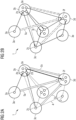
- FIG. 1 shows an exemplary configuration of a communications network 1 with exemplary routings of traffic demands 5a, 5b and 5c following a conventional approach.
- the communications network 1 comprises a plurality of communication nodes 2, wherein a connection 4 between two adjacent communication nodes 2 is called an edge. This is exemplarily illustrated between the communication node 2 and another communication node 2c, which can communicate with each other over the connection 4.
- several communication nodes 2 are aggregated into so-called aggregation nodes 3.
- the communication node 2a is aggregated within aggregation node 3a, whereas other communication nodes 2b, 2d and 2e are aggregated in the aggregation node 3b, for example.
- the communication nodes 2 are for example so-called label edge routers (LER) for routing incoming and outgoing data traffic within the network 1.
- the aggregation nodes 3 are called Meta nodes and are aggregation zones of LERs in a certain region of the network 1.
- the aggregation nodes 3 are centralized aggregation zones of determined economic areas or cities between which a communication shall take place.
- the aggregation nodes 3 can for example be entities of an industry network or of a traffic network, etc.
- the communication network 1, in general, is part-mashed. This means that not all of the communication nodes 2 are connected or connectable with all other communication nodes 2. Instead, there are only several connections 4 (see dotted connections) between several communication nodes 2 implemented in the network 1, which, for example, came from historical evolution of the network 1.
- the connections 4 between respective communication nodes 2 are for example implemented by fibre optic connections.
- other technologies like radio technologies (e.g. 5G) or copper/DSL technologies are applicable as well, in general.
- Figure 1 illustrates a certain scenario of traffic demands 5a, 5b and 5c, according to which certain data volumes have to be transferred between respective communication nodes 2 within the network 1.
- a first traffic demand 5a is between the communication node 2a within aggregation node 3a and another communication node 2f within aggregation node 3d.
- a second traffic demand 5b is between a communication node 2e within aggregation node 3b and again communication node 2f within aggregation node 3d.
- a third traffic demand 5c is between the communication node 2c within aggregation node 3c and again communication node 2f within aggregation node 3d.
- Each traffic demand 5a, 5b and 5c hence, defines a determined volume to be transferred from an origin node to a destination node.
- the origin node for traffic demand 5a is the communication node 2a
- the destination node for the traffic demand 5a is the communication node 2f.
- the origin node is communication node 2e
- the destination node is communication node 2f.
- the origin node is communication node 2c and the destination node is again communication node 2f.
- traffic demands can be defined as demands between aggregation nodes 3, irrespective on which internal communication node 2 within a respective aggregation node 3 the communication starts or ends.
- the demands 5a, 5b and 5c can be defined as demands between the aggregation nodes 3a and 3d (demand 5a), aggregation nodes 3b and 3d (demand 5b) and aggregation nodes 3c and 3d (demand 5c).
- Each traffic demand 5a, 5b and 5c burdens the network 1 with a usage of the network's capacity, i.e. the capacity of respective connections 4 of potential communication paths between the respective communication nodes 2 in the network 1.
- the traffic demand 5a is transferred from communication node 2a to communication node 2f via the communication nodes 2b, 2c, 2d, 2e, and 2f.
- the traffic demand 5b is transferred simply over the connection 4 between the communication nodes 2e and 2f.
- the traffic demand 5c is transferred from communication node 2c to communication node 2f via the communication nodes 2d, 2e, and 2f.
- mainly two drawbacks occur.
- a first drawback lies in the communication paths for the transfer of the traffic demands 5a and 5c being long and rather complicated paths through the network 1. These transfers embed a plurality of communication nodes 2 and connections 4 in the network 1 for transferring the traffic demands 5a and 5c, which can have significant impact on other transfers in the network.
- a second drawback lies in the fact that all three traffic demands 5a to 5c are finally transferred over the connection 4 between the communication nodes 2e and 2f. Hence the link capacity of the connection 4 between the nodes 2e and 2f is loaded to a significant extent. This may lead to a failure or an overload of the connection 4 between nodes 2e and 2f, resulting in increased latency or loss of data, etc.
- Figure 2A shows an exemplary configuration of the communications network 1 with exemplary routings of traffic demands 5a, 5b and 5c (see above) following an alternative approach.
- an alternative path is chosen such that traffic demand 5a is transferred on an alternative communication path starting again in communication node 2a and following the communication nodes 2b, 2d, 2e and 2f.
- the alternative path is, for example, selected by manipulation of link weights of connections 4 in the network 1.
- the scenario according to Figure 2A has the advantage over the scenario of Figure 1 that the communication path for the transfer of the traffic demand 5a has become closer to a short path strategy, thereby keeping the number of involved communication nodes 2 and connections 4 in the network 1 low (at least lower than in the scenario of Figure 1 ) in order to reduce the impact on other transfers.
- the other drawback remains, according to which the connection 4 between the nodes 2e and 2f is still heavily loaded with all three traffic demands 5a to 5c going over this connection of the network 1.
- FIG. 2B shows an exemplary configuration of the communications network 1 according to Figures 1 and 2A , but now with exemplary routings of the traffic demands 5a to 5c following an approach according to the invention.
- a plurality of optimized communication paths regarding the data volumes of all three traffic demands 5a to 5c are selected.
- the traffic demands 5a to 5c all have been split into a plurality of sub-demands, each sub-demand representing a discrete fragment of the data volume of an associated one of the traffic demands 5a to 5c.
- the traffic demands 5a to 5c being only indicated by dashed arrows.
- the scenario according to Figure 2B hence, transfers the overall data volumes of the traffic demands 5a to 5c split into a plurality of fragments (sub-demands) on very different communication paths from respective origins to respective destinations through the network.
- This approach hence, follows a discrete MCFR approach.
- the real value of the scenario according to Figure 2B lies in the fact that the overall data volume of all traffic demands 5a to 5c, is distributed throughout the network, thereby avoiding that significant load is transferred over single segments in the network which can heavily burden single connections 4 in the network.
- Figure 2B solves the drawbacks of the approaches according to Figures 1 and 2A , thereby achieving a reduced impact and influence between transfers of different traffic demands 5a to 5c as best as possible together with a uniform and optimized distribution of the overall capacity usage of the connections 4 in the network 1 for all traffic demands 5 that have to be transferred in the network 1.
- the optimization problem to be solved lies in determining an optimized routing through the network 1 by selecting for each sub-demand as fragment of a respective traffic demand 5 one communication path from a set of optional communication paths, such that a mathematically formulated quadratic stress function (core optimization problem) is minimized.
- This serves the purpose of choosing for all sub-demands of all traffic demands 5 in the network 1 respective communication paths with the effect that the overall capacity usage of connections 4 within the network 1 can be uniformly minimized over the network 1. This avoids connections 4 to be heavily burdened or overloaded, whereas a minor load of other connections 4 could lead to significantly lower such stress.
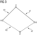
- Figure 3 shows a schematic illustration of optional communication paths k1 and k2 for a routing of fragments (sub-demands) of traffic demands between an origin node o and a destination node d.
- Determined data volume packets of a plurality of sub-demands (into which a traffic demand o, d is split) are to be transferred between o and d.
- the core optimization problem now lies in choosing and determining optimally distributed communication paths for all sub-demands between o and d such that an overall capacity usage of connections within optional communication paths are minimized such that the overall usage of the capacities in the network is uniformly minimized within the network.
- the set of optional communication paths k1 and k2 is specified in advance. This can be done through application of any suitable path planning algorithm that calculates optional communication paths between the origin node o and destination node d for each sub-demand to be transferred. As exemplarily illustrated in Figure 3 , path k1 goes from o over an intermediate node i1 to d. Path k2 goes from o over another intermediate node i2 to d. These are optional communication paths for a routing of data traffic included in each sub-demand between the origin o towards the destination d.
- the planned paths k1, k2 can be stored in advance in the form of a path box that can be accessed by the algorithm for selecting for each sub-demand one path out of the path box.
- Figure 3 further illustrates two exemplary connections that are further referenced to as edges e1 and e2 and that lie in the optional communication paths k1, k2.
- the edge e1 is configured between the intermediate node i1 and the destination d
- the edge e2 is configured between the intermediate node i2 and the destination d.
- the optimization problem lies in determining and selecting distributed communication paths for all sub-demands between o and d such that the overall capacity usage is distributed over both edges e1 and e2.
- fractional capacity usages of all edges within the set of the optional communication paths k1, k2 are calculated for the whole set of sub-demands into which all traffic demands are split.
- such measure includes the calculation of fractional capacity usages of each of the edges e1 and e2 for each of the sub-demands between o and d.
- Fractional capacity usages" of the respective edges means that based on the respective usage capacity limit of each edge, the fraction of the capacity usage is calculated that is required for each sub-demand to be transmitted over this edge.
- each sub-demand between o and d requires half of the maximum usage capacity of each edge e1 and e2 (i.e. 50% of the capacity) when passing over the respective edge.
- the edges e1 and e2 both are burdened with 50% of their usage capacity limit.
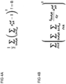
- Figures 4A and 4B show exemplary mathematical formulations of partial optimization problems following the approach as explained above with regard to the Figures 2B and 3 .
- the mathematical formulations of Figures 4A and 4B are represented as so-called Hamiltonian functions, short Hamiltonians.
- the mathematical formulation in Figure 4A is formulated as summed terms of binary variables x p , k o , d that can assume the value "0" or the value "1" (or both with a certain probability) and are represented in a quantum concept processor as bits (or Q-bits as used hereinafter).
- a respective Q-bit x p , k o , d can be set as path variable.
- the respective Q-bit x p , k o , d is set to the value "1" if a respective sub-demand goes over the respective communication path k, and set to the value "0", if not.
- the Hamiltonian must be equal to "0". This is only fulfilled if for each sub-demand p exactly one path k 6 P is chosen such that only one path variable x p , k o , d assumes the value "1" and all other path variables x p , k o , d for other paths have the value "0". Otherwise, if none or more than one path k would be chosen, the condition in Figure 4A would not be fulfilled.
- the path condition mathematically formulated as Hamiltonian in Figure 4A has the effect that exactly one communication path k must be chosen for each sub-demand p in order to consider this sub-demand p for the overall calculation of an optimized routing of all sub-demands in the network.
- the mathematical formulation of the Hamiltonian according to Figure 4B represents the core optimization problem that is formulated as a quadratic stress function taking into account the calculated fractional capacity usages of the edges e out of all edges E in the network (e E E), the edges e lying within the set of optional communication paths k 6 P for all traffic demands o, d.
- the core optimization problem lies in minimizing the Hamiltonian according to Figure 4B in order to find optimized communication paths for all sub-demands p to be transmitted within the network.
- the Hamiltonian of Figure 4B considers summed terms for each edge e within an optional communication path k considering all sub-demands p between all origins o and destinations d.
- the QUBO of Figure 4B then sums all calculated fractional capacity usages t o d p c e of all edges e that are part of optional communication paths k.
- t (o,d,p) here represents the volume of a respective sub-demand p and c e represents the capacity of the respective edge e.
- the fractional capacity usages t o d p c e are connected with the respective Q-bits (path variables) x p , k o , d into path terms.
- the Q-bits x p , k o , d can assume either the value "0" or the value "1" depending on whether an optional path associated with a respective Q-bit x p , k o , d is taken into account or not.
- the Hamiltonian according to Figure 4B may have the following expression: t o , d ,p1 c e1 ⁇ x p 1 , k 1 o , d + t o ,d ,p2 c e1 ⁇ x p2 , k 1 o , d 2 + t o , d ,p1 c e2 ⁇ x p 1 , k2 o , d + t o , d ,p2 c e2 ⁇ x p2 , k2 o , d 2
- the Hamiltonian of Figure 4B is generally solved for all sub-demands in a network by a quantum concept processor that runs through different settings of values for the respective Q-bits x p , k o , d , thereby calculating the respective result of the Hamiltonian.
- the target of doing so is to find the minimum of the Hamiltonian for respectively set values of Q-bits x p , k o , d .
- the respective values of the Q-bits x p , k o , d leading to this minimum are stored and finally define respective communication paths of respective sub-demands.
- each Q-bit x p , k o , d defines one communication path for each sub-demand p as explained above.
- an optimized routing is calculated by selecting for each sub-demand p one communication path k from the set of optional communication paths.
- Figure 5 shows an exemplary schematic illustration of an algorithm performing the approach as explained above.
- Figure 5 shows the processing of the above explained method steps and procedure considering the set of traffic demands 5.
- the traffic demands 5 each are split into respective sub-demands 7 with a determined discrete packet size.
- the pre-processed sub-demands 7 are then input to an algorithmic procedure within the quantum concept processor 6.
- the quantum concept processor 6 according to Figure 5 is configured to solve the optimization problem by means of quantum annealing emulation.
- the quantum concept processor 6 applies the mathematical formulation of the overall optimization problem according to Figures 4A and 4B .
- the quantum concept processor 6 then calculates for the sub-demands 7 an optimized routing solution of the optimization problem according to Figure 4B under consideration of the constraint according to Figure 4A .
- the finally calculated minimum of the optimization problem according to Figure 4B is then output from the quantum concept processor 6 for the respective sub-demands 7.
- the determined communication paths k according to the found optimum of the optimization problem are then stored for the sub-demands 7.
- the algorithm is then finished.
- the herein explained approach is primarily applicable to communication networks. However, the approach can also be applied to any other networks, like railway networks, energy grids, traffic networks, etc. in which certain "traffic” or “load” has to be transmitted throughout the network over optimized paths.
Landscapes
- Engineering & Computer Science (AREA)
- Computer Networks & Wireless Communication (AREA)
- Signal Processing (AREA)
- Data Exchanges In Wide-Area Networks (AREA)
Claims (13)
- Computerimplementiertes Verfahren zur Optimierung einer Nutzungsverteilung in einem Kommunikationsnetz (1), in dem Datenverkehr geleitet wird, wobei das Kommunikationsnetz (1) eine Vielzahl von Kommunikationsknoten (2) aufweist, die für eine Leitweglenkung des Datenverkehrs über Kanten (4) von Kommunikationspfaden verbindbar sind, wobei das Verfahren die folgenden Schritte umfasst:- Erfassen eines Satzes von Verkehrsanforderungen (5), wobei jede Verkehrsanforderung (5a-5c) eine Übertragung eines bestimmten Datenvolumens von einem Ursprungsknoten (o) an einen Zielknoten (d) unter der Vielzahl von Kommunikationsknoten (2) angibt,- Aufteilen der Verkehrsanforderungen (5a-5c) in Teilanforderungen (7, p),- Angeben eines Satzes von optionalen Kommunikationspfaden (k) für eine individuelle Leitweglenkung jeder Teilanforderung (7, p), wobei den Kanten (e) innerhalb des Satzes von optionalen Kommunikationspfaden (k) eine jeweilige Nutzungskapazitätsgrenze zugeordnet ist,- Berechnen, für jede Teilanforderung (7, p), von fraktionellen Kapazitätsnutzungen der Kanten (e) innerhalb des Satzes von optionalen Kommunikationspfaden (k), wobei die fraktionellen Kapazitätsnutzungen auf der Grundlage der jeweiligen Nutzungskapazitätsgrenze berechnet werden,- Formulieren der berechneten fraktionellen Kapazitätsnutzungen als Terme einer quadratischen Belastungsfunktion,- Bestimmen, mithilfe eines Quantenkonzept-Prozessors (6), einer optimierten Leitweglenkung durch Auswählen, für jede Teilanforderung (7, p), eines Kommunikationspfades (k1, k2) aus dem Satz von optionalen Kommunikationspfaden (k), derart, dass die quadratische Belastungsfunktion minimiert ist.
- Verfahren nach Anspruch 1, darüber hinaus die folgenden Schritte umfassend:- Angeben eines Satzes von Pfadvariablen, wobei jede Pfadvariable einer der Teilanforderungen (7, p) und einem Kommunikationspfad (k1, k2) aus dem Satz von optionalen Kommunikationspfaden (k) zugeordnet ist,- Formulieren, in der quadratischen Belastungsfunktion, von Pfadtermen, welche die berechneten fraktionellen Kapazitätsnutzungen der Kanten (e) eines jeweiligen Kommunikationspfades (k1, k2) aus dem Satz von optionalen Kommunikationspfaden (k) mit der Pfadvariablen verbinden, die dem jeweiligen Kommunikationspfad (k1, k2) aus dem Satz von optionalen Kommunikationspfaden (k) zugeordnet ist,- Berechnen der Pfadterme mithilfe des Quantenkonzept-Prozessors (6), um für jede Teilanforderung (7, p) einen Kommunikationspfad (k1, k2) aus dem Satz von optionalen Kommunikationspfaden (k) zu wählen, derart, dass die quadratische Belastungsfunktion minimiert ist.
- Verfahren nach Anspruch 2, wobei die Pfadterme unter Berücksichtigung einer Pfadbedingung berechnet werden, dass jede Teilanforderung (7, p) entlang genau einem Kommunikationspfad (k1, k2) aus dem Satz von optionalen Kommunikationspfaden (k) geleitet wird.
- Verfahren nach einem der Ansprüche 1 bis 3, wobei die Verkehrsanforderungen (5) in Teilanforderungen (7, p) mit bestimmten diskreten Datenvolumina aufgeteilt werden.
- Verfahren nach einem der Ansprüche 1 bis 4, wobei die quadratische Belastungsfunktion unter Berücksichtigung einer oder beider der folgenden Randbedingungen für den Satz von Verkehrsanforderungen (5) oder für die jeweiligen Teilanforderungen (7, p) formuliert wird:- Organisation des Kommunikationsnetzes (1) in verschiedene Netzbereiche,- Latenz des Kommunikationsnetzes (1).
- Verfahren nach einem der Ansprüche 1 bis 5, wobei der Satz von optionalen Kommunikationspfaden (k) für eine individuelle Leitweglenkung jeder Teilanforderung (7, p) unter Berücksichtigung von einer oder mehreren der folgenden Randbedingungen angegeben wird:- ein oder mehrere redundante optionale Kommunikationspfade (k), die einem Teilnetz des Kommunikationsnetzes (1) zugeordnet sind,- Organisation des Kommunikationsnetzes (1) in verschiedene Netzbereiche,- Latenz des Kommunikationsnetzes (1).
- Verfahren nach einem der Ansprüche 1 bis 6, wobei der Satz von optionalen Kommunikationspfaden (k) für eine individuelle Leitweglenkung jeder Teilanforderung (7, p) so angegeben wird, dass für topologisch nahe Ursprungs- und Zielknoten (o, d) eine kleinere Anzahl von optionalen Kommunikationspfaden (k) ausgewählt wird als für topologisch entfernte Ursprungs- und Zielknoten (o, d).
- Verfahren nach einem der Ansprüche 1 bis 7, wobei die quadratische Belastungsfunktion als eine quadratische binäre Optimierungsfunktion ohne Randbedingungen (QUBO) formuliert ist.
- Quantenkonzept-Prozessor (6), insbesondere eine digitale Annealing-Verarbeitungseinheit oder eine Quanten-Annealing-Verarbeitungseinheit, die dafür ausgelegt ist, einen oder mehrere Schritte eines Verfahrens nach einem der Ansprüche 1 bis 8 durchzuführen.
- Computerprogramm, wobei das Computerprogramm Anweisungen umfasst, die, wenn das Programm von einem oder mehreren Prozessoren ausgeführt wird, jeden des einen oder der mehreren Prozessoren dazu veranlassen, einen oder mehrere Schritte eines Verfahrens nach einem der Ansprüche 1 bis 8 durchzuführen.
- Computerlesbares Speichermedium, auf dem das Computerprogramm nach Anspruch 10 gespeichert ist.
- System für einen Netzplaner, wobei das Arbeitsplatzsystem Prüfmittel aufweist, die in Hardware oder Software implementiert sind, das dafür ausgelegt ist, eine optimierte Leitweglenkung zu prüfen, die durch ein Verfahren nach einem der Ansprüche 1 bis 8 bestimmt wird.
- Schnittstellenanordnung mit einer oder mehreren Schnittstellen zu einer Vielzahl von Kommunikationsknoten (2) eines Kommunikationsnetzes (1), in dem Datenverkehr geleitet wird, wobei die Schnittstellenanordnung dafür ausgelegt ist, eine durch ein Verfahren nach einem der Ansprüche 1 bis 8 bestimmte optimierte Leitweglenkung automatisch an den Kommunikationsknoten (2) des Kommunikationsnetzes (1) zum Einsatz zu bringen.
Priority Applications (3)
| Application Number | Priority Date | Filing Date | Title |
|---|---|---|---|
| PCT/EP2022/075647 WO2023041645A1 (en) | 2021-09-20 | 2022-09-15 | Method for optimizing a usage distribution in a communications network |
| US18/288,744 US12250140B2 (en) | 2021-09-20 | 2022-09-15 | Method of optimizing a usage distribution in a communications network |
| JP2023570454A JP7739460B2 (ja) | 2021-09-20 | 2022-09-15 | 通信ネットワークにおける使用率分布を最適化するための方法 |
Applications Claiming Priority (1)
| Application Number | Priority Date | Filing Date | Title |
|---|---|---|---|
| DE102021004716 | 2021-09-20 |
Publications (2)
| Publication Number | Publication Date |
|---|---|
| EP4152727A1 EP4152727A1 (de) | 2023-03-22 |
| EP4152727B1 true EP4152727B1 (de) | 2023-11-29 |
Family
ID=78413807
Family Applications (1)
| Application Number | Title | Priority Date | Filing Date |
|---|---|---|---|
| EP21205005.8A Active EP4152727B1 (de) | 2021-09-20 | 2021-10-27 | Verfahren zur optimierung einer nutzungsverteilung in einem kommunikationsnetz |
Country Status (1)
| Country | Link |
|---|---|
| EP (1) | EP4152727B1 (de) |
Family Cites Families (2)
| Publication number | Priority date | Publication date | Assignee | Title |
|---|---|---|---|---|
| US10268964B2 (en) * | 2016-03-30 | 2019-04-23 | 1Qb Information Technologies Inc. | Method and system for solving a minimum connected dominating set problem using quantum annealing for distance optimization |
| CN111512600B (zh) * | 2017-12-21 | 2022-04-29 | 瑞典爱立信有限公司 | 在电信网络中分配流量的方法和装置 |
-
2021
- 2021-10-27 EP EP21205005.8A patent/EP4152727B1/de active Active
Also Published As
| Publication number | Publication date |
|---|---|
| EP4152727A1 (de) | 2023-03-22 |
Similar Documents
| Publication | Publication Date | Title |
|---|---|---|
| US7916657B2 (en) | Network performance and reliability evaluation taking into account abstract components | |
| US7864751B2 (en) | Traffic engineering method, system and computer program product for managing traffic over dynamic networks during both normal and unexpected traffic scenarios | |
| Beshley et al. | Adaptive flow routing model in SDN | |
| Doolittle et al. | Robust multiobjective optimization with application to internet routing | |
| US9401868B2 (en) | Method of traffic engineering for provisioning routing and storage in content-oriented networks | |
| Shvedov et al. | Determining shortest paths between two arbitrary nodes in a composite transport network using segment routing | |
| US8964738B2 (en) | Path computation element protocol support for large-scale concurrent path computation | |
| Paris et al. | Dynamic control for failure recovery and flow reconfiguration in SDN | |
| EP4152726B1 (de) | Verfahren zur optimierung einer leitweglenkung in einem kommunikationsnetzwerk | |
| US12237993B2 (en) | Method of optimizing a routing in a communications network | |
| US12250140B2 (en) | Method of optimizing a usage distribution in a communications network | |
| Montana et al. | Adaptive reconfiguration of data networks using genetic algorithms | |
| EP4152727A1 (de) | Verfahren zur optimierung einer nutzungsverteilung in einem kommunikationsnetz | |
| Magnouche et al. | Leveraging micro-services for ultra-low latency: An optimization model for service function chains placement | |
| Liu et al. | Dependency aware and delay guaranteed sfc placement in multi-domain networks | |
| Wu et al. | A matheuristic for a telecommunication network design problem with traffic grooming | |
| Lemeshko et al. | Quality of Service Protection Scheme under Fast ReRoute and Traffic Policing Based on Tensor Model of Multiservice Network | |
| Liu et al. | Sdn-based optimized controller deployment strategy for satellite network | |
| Lemeshko et al. | Tensor based load balancing under self-similar traffic properties with guaranteed QoS | |
| Karasan et al. | Robust path design algorithms for traffic engineering with restoration in MPLS networks | |
| Yetginer et al. | Robust path design algorithms for traffic engineering with restoration in MPLS networks | |
| US20160248672A1 (en) | Information processing device, verification method and system | |
| JP7434523B2 (ja) | 大域的並行最適化経路を計算する方法、機器及びコンピュータ読み取り可能な記憶媒体 | |
| Erbati | Towards the optimal orchestration of service function chains to enable ultra-reliable low latency communication in an NFV-enabled network | |
| Karimova | Streaming model of traffic management in the telecommunication network |
Legal Events
| Date | Code | Title | Description |
|---|---|---|---|
| PUAI | Public reference made under article 153(3) epc to a published international application that has entered the european phase |
Free format text: ORIGINAL CODE: 0009012 |
|
| STAA | Information on the status of an ep patent application or granted ep patent |
Free format text: STATUS: THE APPLICATION HAS BEEN PUBLISHED |
|
| STAA | Information on the status of an ep patent application or granted ep patent |
Free format text: STATUS: REQUEST FOR EXAMINATION WAS MADE |
|
| AK | Designated contracting states |
Kind code of ref document: A1 Designated state(s): AL AT BE BG CH CY CZ DE DK EE ES FI FR GB GR HR HU IE IS IT LI LT LU LV MC MK MT NL NO PL PT RO RS SE SI SK SM TR |
|
| 17P | Request for examination filed |
Effective date: 20230315 |
|
| RBV | Designated contracting states (corrected) |
Designated state(s): AL AT BE BG CH CY CZ DE DK EE ES FI FR GB GR HR HU IE IS IT LI LT LU LV MC MK MT NL NO PL PT RO RS SE SI SK SM TR |
|
| GRAP | Despatch of communication of intention to grant a patent |
Free format text: ORIGINAL CODE: EPIDOSNIGR1 |
|
| STAA | Information on the status of an ep patent application or granted ep patent |
Free format text: STATUS: GRANT OF PATENT IS INTENDED |
|
| INTG | Intention to grant announced |
Effective date: 20230622 |
|
| GRAS | Grant fee paid |
Free format text: ORIGINAL CODE: EPIDOSNIGR3 |
|
| GRAA | (expected) grant |
Free format text: ORIGINAL CODE: 0009210 |
|
| STAA | Information on the status of an ep patent application or granted ep patent |
Free format text: STATUS: THE PATENT HAS BEEN GRANTED |
|
| AK | Designated contracting states |
Kind code of ref document: B1 Designated state(s): AL AT BE BG CH CY CZ DE DK EE ES FI FR GB GR HR HU IE IS IT LI LT LU LV MC MK MT NL NO PL PT RO RS SE SI SK SM TR |
|
| REG | Reference to a national code |
Ref country code: GB Ref legal event code: FG4D |
|
| REG | Reference to a national code |
Ref country code: CH Ref legal event code: EP |
|
| REG | Reference to a national code |
Ref country code: DE Ref legal event code: R096 Ref document number: 602021007277 Country of ref document: DE |
|
| REG | Reference to a national code |
Ref country code: IE Ref legal event code: FG4D |
|
| REG | Reference to a national code |
Ref country code: LT Ref legal event code: MG9D |
|
| REG | Reference to a national code |
Ref country code: NL Ref legal event code: MP Effective date: 20231129 |
|
| PG25 | Lapsed in a contracting state [announced via postgrant information from national office to epo] |
Ref country code: GR Free format text: LAPSE BECAUSE OF FAILURE TO SUBMIT A TRANSLATION OF THE DESCRIPTION OR TO PAY THE FEE WITHIN THE PRESCRIBED TIME-LIMIT Effective date: 20240301 |
|
| PG25 | Lapsed in a contracting state [announced via postgrant information from national office to epo] |
Ref country code: IS Free format text: LAPSE BECAUSE OF FAILURE TO SUBMIT A TRANSLATION OF THE DESCRIPTION OR TO PAY THE FEE WITHIN THE PRESCRIBED TIME-LIMIT Effective date: 20240329 |
|
| PG25 | Lapsed in a contracting state [announced via postgrant information from national office to epo] |
Ref country code: LT Free format text: LAPSE BECAUSE OF FAILURE TO SUBMIT A TRANSLATION OF THE DESCRIPTION OR TO PAY THE FEE WITHIN THE PRESCRIBED TIME-LIMIT Effective date: 20231129 |
|
| PG25 | Lapsed in a contracting state [announced via postgrant information from national office to epo] |
Ref country code: ES Free format text: LAPSE BECAUSE OF FAILURE TO SUBMIT A TRANSLATION OF THE DESCRIPTION OR TO PAY THE FEE WITHIN THE PRESCRIBED TIME-LIMIT Effective date: 20231129 |
|
| PG25 | Lapsed in a contracting state [announced via postgrant information from national office to epo] |
Ref country code: LT Free format text: LAPSE BECAUSE OF FAILURE TO SUBMIT A TRANSLATION OF THE DESCRIPTION OR TO PAY THE FEE WITHIN THE PRESCRIBED TIME-LIMIT Effective date: 20231129 Ref country code: IS Free format text: LAPSE BECAUSE OF FAILURE TO SUBMIT A TRANSLATION OF THE DESCRIPTION OR TO PAY THE FEE WITHIN THE PRESCRIBED TIME-LIMIT Effective date: 20240329 Ref country code: GR Free format text: LAPSE BECAUSE OF FAILURE TO SUBMIT A TRANSLATION OF THE DESCRIPTION OR TO PAY THE FEE WITHIN THE PRESCRIBED TIME-LIMIT Effective date: 20240301 Ref country code: ES Free format text: LAPSE BECAUSE OF FAILURE TO SUBMIT A TRANSLATION OF THE DESCRIPTION OR TO PAY THE FEE WITHIN THE PRESCRIBED TIME-LIMIT Effective date: 20231129 Ref country code: BG Free format text: LAPSE BECAUSE OF FAILURE TO SUBMIT A TRANSLATION OF THE DESCRIPTION OR TO PAY THE FEE WITHIN THE PRESCRIBED TIME-LIMIT Effective date: 20240229 |
|
| REG | Reference to a national code |
Ref country code: AT Ref legal event code: MK05 Ref document number: 1637273 Country of ref document: AT Kind code of ref document: T Effective date: 20231129 |
|
| PG25 | Lapsed in a contracting state [announced via postgrant information from national office to epo] |
Ref country code: NL Free format text: LAPSE BECAUSE OF FAILURE TO SUBMIT A TRANSLATION OF THE DESCRIPTION OR TO PAY THE FEE WITHIN THE PRESCRIBED TIME-LIMIT Effective date: 20231129 |
|
| PG25 | Lapsed in a contracting state [announced via postgrant information from national office to epo] |
Ref country code: SE Free format text: LAPSE BECAUSE OF FAILURE TO SUBMIT A TRANSLATION OF THE DESCRIPTION OR TO PAY THE FEE WITHIN THE PRESCRIBED TIME-LIMIT Effective date: 20231129 Ref country code: RS Free format text: LAPSE BECAUSE OF FAILURE TO SUBMIT A TRANSLATION OF THE DESCRIPTION OR TO PAY THE FEE WITHIN THE PRESCRIBED TIME-LIMIT Effective date: 20231129 Ref country code: PL Free format text: LAPSE BECAUSE OF FAILURE TO SUBMIT A TRANSLATION OF THE DESCRIPTION OR TO PAY THE FEE WITHIN THE PRESCRIBED TIME-LIMIT Effective date: 20231129 Ref country code: NO Free format text: LAPSE BECAUSE OF FAILURE TO SUBMIT A TRANSLATION OF THE DESCRIPTION OR TO PAY THE FEE WITHIN THE PRESCRIBED TIME-LIMIT Effective date: 20240229 Ref country code: NL Free format text: LAPSE BECAUSE OF FAILURE TO SUBMIT A TRANSLATION OF THE DESCRIPTION OR TO PAY THE FEE WITHIN THE PRESCRIBED TIME-LIMIT Effective date: 20231129 Ref country code: LV Free format text: LAPSE BECAUSE OF FAILURE TO SUBMIT A TRANSLATION OF THE DESCRIPTION OR TO PAY THE FEE WITHIN THE PRESCRIBED TIME-LIMIT Effective date: 20231129 Ref country code: HR Free format text: LAPSE BECAUSE OF FAILURE TO SUBMIT A TRANSLATION OF THE DESCRIPTION OR TO PAY THE FEE WITHIN THE PRESCRIBED TIME-LIMIT Effective date: 20231129 |
|
| PG25 | Lapsed in a contracting state [announced via postgrant information from national office to epo] |
Ref country code: DK Free format text: LAPSE BECAUSE OF FAILURE TO SUBMIT A TRANSLATION OF THE DESCRIPTION OR TO PAY THE FEE WITHIN THE PRESCRIBED TIME-LIMIT Effective date: 20231129 |
|
| PG25 | Lapsed in a contracting state [announced via postgrant information from national office to epo] |
Ref country code: CZ Free format text: LAPSE BECAUSE OF FAILURE TO SUBMIT A TRANSLATION OF THE DESCRIPTION OR TO PAY THE FEE WITHIN THE PRESCRIBED TIME-LIMIT Effective date: 20231129 Ref country code: AT Free format text: LAPSE BECAUSE OF FAILURE TO SUBMIT A TRANSLATION OF THE DESCRIPTION OR TO PAY THE FEE WITHIN THE PRESCRIBED TIME-LIMIT Effective date: 20231129 |
|
| PG25 | Lapsed in a contracting state [announced via postgrant information from national office to epo] |
Ref country code: SK Free format text: LAPSE BECAUSE OF FAILURE TO SUBMIT A TRANSLATION OF THE DESCRIPTION OR TO PAY THE FEE WITHIN THE PRESCRIBED TIME-LIMIT Effective date: 20231129 |
|
| PG25 | Lapsed in a contracting state [announced via postgrant information from national office to epo] |
Ref country code: SM Free format text: LAPSE BECAUSE OF FAILURE TO SUBMIT A TRANSLATION OF THE DESCRIPTION OR TO PAY THE FEE WITHIN THE PRESCRIBED TIME-LIMIT Effective date: 20231129 Ref country code: SK Free format text: LAPSE BECAUSE OF FAILURE TO SUBMIT A TRANSLATION OF THE DESCRIPTION OR TO PAY THE FEE WITHIN THE PRESCRIBED TIME-LIMIT Effective date: 20231129 Ref country code: RO Free format text: LAPSE BECAUSE OF FAILURE TO SUBMIT A TRANSLATION OF THE DESCRIPTION OR TO PAY THE FEE WITHIN THE PRESCRIBED TIME-LIMIT Effective date: 20231129 Ref country code: IT Free format text: LAPSE BECAUSE OF FAILURE TO SUBMIT A TRANSLATION OF THE DESCRIPTION OR TO PAY THE FEE WITHIN THE PRESCRIBED TIME-LIMIT Effective date: 20231129 Ref country code: EE Free format text: LAPSE BECAUSE OF FAILURE TO SUBMIT A TRANSLATION OF THE DESCRIPTION OR TO PAY THE FEE WITHIN THE PRESCRIBED TIME-LIMIT Effective date: 20231129 Ref country code: DK Free format text: LAPSE BECAUSE OF FAILURE TO SUBMIT A TRANSLATION OF THE DESCRIPTION OR TO PAY THE FEE WITHIN THE PRESCRIBED TIME-LIMIT Effective date: 20231129 Ref country code: CZ Free format text: LAPSE BECAUSE OF FAILURE TO SUBMIT A TRANSLATION OF THE DESCRIPTION OR TO PAY THE FEE WITHIN THE PRESCRIBED TIME-LIMIT Effective date: 20231129 Ref country code: AT Free format text: LAPSE BECAUSE OF FAILURE TO SUBMIT A TRANSLATION OF THE DESCRIPTION OR TO PAY THE FEE WITHIN THE PRESCRIBED TIME-LIMIT Effective date: 20231129 |
|
| PG25 | Lapsed in a contracting state [announced via postgrant information from national office to epo] |
Ref country code: PT Free format text: LAPSE BECAUSE OF FAILURE TO SUBMIT A TRANSLATION OF THE DESCRIPTION OR TO PAY THE FEE WITHIN THE PRESCRIBED TIME-LIMIT Effective date: 20240401 |
|
| PG25 | Lapsed in a contracting state [announced via postgrant information from national office to epo] |
Ref country code: PT Free format text: LAPSE BECAUSE OF FAILURE TO SUBMIT A TRANSLATION OF THE DESCRIPTION OR TO PAY THE FEE WITHIN THE PRESCRIBED TIME-LIMIT Effective date: 20240401 |
|
| REG | Reference to a national code |
Ref country code: DE Ref legal event code: R097 Ref document number: 602021007277 Country of ref document: DE |
|
| PLBE | No opposition filed within time limit |
Free format text: ORIGINAL CODE: 0009261 |
|
| STAA | Information on the status of an ep patent application or granted ep patent |
Free format text: STATUS: NO OPPOSITION FILED WITHIN TIME LIMIT |
|
| PG25 | Lapsed in a contracting state [announced via postgrant information from national office to epo] |
Ref country code: SI Free format text: LAPSE BECAUSE OF FAILURE TO SUBMIT A TRANSLATION OF THE DESCRIPTION OR TO PAY THE FEE WITHIN THE PRESCRIBED TIME-LIMIT Effective date: 20231129 |
|
| PG25 | Lapsed in a contracting state [announced via postgrant information from national office to epo] |
Ref country code: SI Free format text: LAPSE BECAUSE OF FAILURE TO SUBMIT A TRANSLATION OF THE DESCRIPTION OR TO PAY THE FEE WITHIN THE PRESCRIBED TIME-LIMIT Effective date: 20231129 |
|
| 26N | No opposition filed |
Effective date: 20240830 |
|
| REG | Reference to a national code |
Ref country code: DE Ref legal event code: R081 Ref document number: 602021007277 Country of ref document: DE Owner name: FSAS TECHNOLOGIES GMBH, DE Free format text: FORMER OWNERS: DEUTSCHE TELEKOM AG, 53113 BONN, DE; FUJITSU TECHNOLOGY SOLUTIONS GMBH, 80807 MUENCHEN, DE Ref country code: DE Ref legal event code: R081 Ref document number: 602021007277 Country of ref document: DE Owner name: DEUTSCHE TELEKOM AG, DE Free format text: FORMER OWNERS: DEUTSCHE TELEKOM AG, 53113 BONN, DE; FUJITSU TECHNOLOGY SOLUTIONS GMBH, 80807 MUENCHEN, DE Ref country code: DE Ref legal event code: R081 Ref document number: 602021007277 Country of ref document: DE Owner name: FUJITSU GERMANY GMBH, DE Free format text: FORMER OWNERS: DEUTSCHE TELEKOM AG, 53113 BONN, DE; FUJITSU TECHNOLOGY SOLUTIONS GMBH, 80807 MUENCHEN, DE |
|
| REG | Reference to a national code |
Ref country code: CH Ref legal event code: PL |
|
| PG25 | Lapsed in a contracting state [announced via postgrant information from national office to epo] |
Ref country code: MC Free format text: LAPSE BECAUSE OF FAILURE TO SUBMIT A TRANSLATION OF THE DESCRIPTION OR TO PAY THE FEE WITHIN THE PRESCRIBED TIME-LIMIT Effective date: 20231129 |
|
| PG25 | Lapsed in a contracting state [announced via postgrant information from national office to epo] |
Ref country code: LU Free format text: LAPSE BECAUSE OF NON-PAYMENT OF DUE FEES Effective date: 20241027 Ref country code: BE Free format text: LAPSE BECAUSE OF NON-PAYMENT OF DUE FEES Effective date: 20241031 |
|
| PG25 | Lapsed in a contracting state [announced via postgrant information from national office to epo] |
Ref country code: CH Free format text: LAPSE BECAUSE OF NON-PAYMENT OF DUE FEES Effective date: 20241031 |
|
| REG | Reference to a national code |
Ref country code: BE Ref legal event code: MM Effective date: 20241031 |
|
| PG25 | Lapsed in a contracting state [announced via postgrant information from national office to epo] |
Ref country code: FI Free format text: LAPSE BECAUSE OF FAILURE TO SUBMIT A TRANSLATION OF THE DESCRIPTION OR TO PAY THE FEE WITHIN THE PRESCRIBED TIME-LIMIT Effective date: 20231129 |
|
| PG25 | Lapsed in a contracting state [announced via postgrant information from national office to epo] |
Ref country code: IE Free format text: LAPSE BECAUSE OF NON-PAYMENT OF DUE FEES Effective date: 20241027 |
|
| REG | Reference to a national code |
Ref country code: DE Ref legal event code: R081 Ref document number: 602021007277 Country of ref document: DE Owner name: DEUTSCHE TELEKOM AG, DE Free format text: FORMER OWNERS: DEUTSCHE TELEKOM AG, 53113 BONN, DE; FSAS TECHNOLOGIES GMBH, 80807 MUENCHEN, DE Ref country code: DE Ref legal event code: R081 Ref document number: 602021007277 Country of ref document: DE Owner name: FUJITSU GERMANY GMBH, DE Free format text: FORMER OWNERS: DEUTSCHE TELEKOM AG, 53113 BONN, DE; FSAS TECHNOLOGIES GMBH, 80807 MUENCHEN, DE |
|
| REG | Reference to a national code |
Ref country code: GB Ref legal event code: 732E Free format text: REGISTERED BETWEEN 20251127 AND 20251203 |
|
| PGFP | Annual fee paid to national office [announced via postgrant information from national office to epo] |
Ref country code: DE Payment date: 20251024 Year of fee payment: 5 |
|
| PGFP | Annual fee paid to national office [announced via postgrant information from national office to epo] |
Ref country code: GB Payment date: 20251024 Year of fee payment: 5 |
|
| PGFP | Annual fee paid to national office [announced via postgrant information from national office to epo] |
Ref country code: FR Payment date: 20251027 Year of fee payment: 5 |
|
| PG25 | Lapsed in a contracting state [announced via postgrant information from national office to epo] |
Ref country code: CY Free format text: LAPSE BECAUSE OF FAILURE TO SUBMIT A TRANSLATION OF THE DESCRIPTION OR TO PAY THE FEE WITHIN THE PRESCRIBED TIME-LIMIT; INVALID AB INITIO Effective date: 20211027 |
|
| PG25 | Lapsed in a contracting state [announced via postgrant information from national office to epo] |
Ref country code: HU Free format text: LAPSE BECAUSE OF FAILURE TO SUBMIT A TRANSLATION OF THE DESCRIPTION OR TO PAY THE FEE WITHIN THE PRESCRIBED TIME-LIMIT; INVALID AB INITIO Effective date: 20211027 |