EP4152706B1 - Ppdu-übertragungsverfahren und zugehörige vorrichtung - Google Patents
Ppdu-übertragungsverfahren und zugehörige vorrichtung Download PDFInfo
- Publication number
- EP4152706B1 EP4152706B1 EP21818276.4A EP21818276A EP4152706B1 EP 4152706 B1 EP4152706 B1 EP 4152706B1 EP 21818276 A EP21818276 A EP 21818276A EP 4152706 B1 EP4152706 B1 EP 4152706B1
- Authority
- EP
- European Patent Office
- Prior art keywords
- eht
- sig
- subfield
- ppdu
- ndp
- Prior art date
- Legal status (The legal status is an assumption and is not a legal conclusion. Google has not performed a legal analysis and makes no representation as to the accuracy of the status listed.)
- Active
Links
Images


Classifications
-
- H—ELECTRICITY
- H04—ELECTRIC COMMUNICATION TECHNIQUE
- H04L—TRANSMISSION OF DIGITAL INFORMATION, e.g. TELEGRAPHIC COMMUNICATION
- H04L1/00—Arrangements for detecting or preventing errors in the information received
- H04L1/0001—Systems modifying transmission characteristics according to link quality, e.g. power backoff
- H04L1/0002—Systems modifying transmission characteristics according to link quality, e.g. power backoff by adapting the transmission rate
- H04L1/0003—Systems modifying transmission characteristics according to link quality, e.g. power backoff by adapting the transmission rate by switching between different modulation schemes
-
- H—ELECTRICITY
- H04—ELECTRIC COMMUNICATION TECHNIQUE
- H04L—TRANSMISSION OF DIGITAL INFORMATION, e.g. TELEGRAPHIC COMMUNICATION
- H04L1/00—Arrangements for detecting or preventing errors in the information received
- H04L1/004—Arrangements for detecting or preventing errors in the information received by using forward error control
- H04L1/0041—Arrangements at the transmitter end
-
- H—ELECTRICITY
- H04—ELECTRIC COMMUNICATION TECHNIQUE
- H04L—TRANSMISSION OF DIGITAL INFORMATION, e.g. TELEGRAPHIC COMMUNICATION
- H04L1/00—Arrangements for detecting or preventing errors in the information received
- H04L1/004—Arrangements for detecting or preventing errors in the information received by using forward error control
- H04L1/0056—Systems characterized by the type of code used
- H04L1/0057—Block codes
-
- H—ELECTRICITY
- H04—ELECTRIC COMMUNICATION TECHNIQUE
- H04L—TRANSMISSION OF DIGITAL INFORMATION, e.g. TELEGRAPHIC COMMUNICATION
- H04L25/00—Baseband systems
- H04L25/02—Details ; arrangements for supplying electrical power along data transmission lines
- H04L25/0202—Channel estimation
-
- H—ELECTRICITY
- H04—ELECTRIC COMMUNICATION TECHNIQUE
- H04L—TRANSMISSION OF DIGITAL INFORMATION, e.g. TELEGRAPHIC COMMUNICATION
- H04L25/00—Baseband systems
- H04L25/02—Details ; arrangements for supplying electrical power along data transmission lines
- H04L25/0202—Channel estimation
- H04L25/0224—Channel estimation using sounding signals
-
- H—ELECTRICITY
- H04—ELECTRIC COMMUNICATION TECHNIQUE
- H04L—TRANSMISSION OF DIGITAL INFORMATION, e.g. TELEGRAPHIC COMMUNICATION
- H04L27/00—Modulated-carrier systems
- H04L27/18—Phase-modulated carrier systems, i.e. using phase-shift keying
- H04L27/20—Modulator circuits; Transmitter circuits
- H04L27/2032—Modulator circuits; Transmitter circuits for discrete phase modulation, e.g. in which the phase of the carrier is modulated in a nominally instantaneous manner
- H04L27/2053—Modulator circuits; Transmitter circuits for discrete phase modulation, e.g. in which the phase of the carrier is modulated in a nominally instantaneous manner using more than one carrier, e.g. carriers with different phases
-
- H—ELECTRICITY
- H04—ELECTRIC COMMUNICATION TECHNIQUE
- H04L—TRANSMISSION OF DIGITAL INFORMATION, e.g. TELEGRAPHIC COMMUNICATION
- H04L27/00—Modulated-carrier systems
- H04L27/26—Systems using multi-frequency codes
- H04L27/2601—Multicarrier modulation systems
- H04L27/2602—Signal structure
-
- H—ELECTRICITY
- H04—ELECTRIC COMMUNICATION TECHNIQUE
- H04L—TRANSMISSION OF DIGITAL INFORMATION, e.g. TELEGRAPHIC COMMUNICATION
- H04L27/00—Modulated-carrier systems
- H04L27/26—Systems using multi-frequency codes
- H04L27/2601—Multicarrier modulation systems
- H04L27/2602—Signal structure
- H04L27/261—Details of reference signals
- H04L27/2613—Structure of the reference signals
-
- H—ELECTRICITY
- H04—ELECTRIC COMMUNICATION TECHNIQUE
- H04L—TRANSMISSION OF DIGITAL INFORMATION, e.g. TELEGRAPHIC COMMUNICATION
- H04L5/00—Arrangements affording multiple use of the transmission path
- H04L5/003—Arrangements for allocating sub-channels of the transmission path
- H04L5/0044—Allocation of payload; Allocation of data channels, e.g. PDSCH or PUSCH
-
- H—ELECTRICITY
- H04—ELECTRIC COMMUNICATION TECHNIQUE
- H04W—WIRELESS COMMUNICATION NETWORKS
- H04W84/00—Network topologies
- H04W84/02—Hierarchically pre-organised networks, e.g. paging networks, cellular networks, WLAN [Wireless Local Area Network] or WLL [Wireless Local Loop]
- H04W84/10—Small scale networks; Flat hierarchical networks
- H04W84/12—WLAN [Wireless Local Area Networks]
-
- H—ELECTRICITY
- H04—ELECTRIC COMMUNICATION TECHNIQUE
- H04L—TRANSMISSION OF DIGITAL INFORMATION, e.g. TELEGRAPHIC COMMUNICATION
- H04L1/00—Arrangements for detecting or preventing errors in the information received
- H04L1/0001—Systems modifying transmission characteristics according to link quality, e.g. power backoff
- H04L1/0023—Systems modifying transmission characteristics according to link quality, e.g. power backoff characterised by the signalling
- H04L1/0025—Transmission of mode-switching indication
-
- H—ELECTRICITY
- H04—ELECTRIC COMMUNICATION TECHNIQUE
- H04L—TRANSMISSION OF DIGITAL INFORMATION, e.g. TELEGRAPHIC COMMUNICATION
- H04L1/00—Arrangements for detecting or preventing errors in the information received
- H04L1/004—Arrangements for detecting or preventing errors in the information received by using forward error control
- H04L1/0075—Transmission of coding parameters to receiver
-
- H—ELECTRICITY
- H04—ELECTRIC COMMUNICATION TECHNIQUE
- H04L—TRANSMISSION OF DIGITAL INFORMATION, e.g. TELEGRAPHIC COMMUNICATION
- H04L1/00—Arrangements for detecting or preventing errors in the information received
- H04L1/02—Arrangements for detecting or preventing errors in the information received by diversity reception
- H04L1/06—Arrangements for detecting or preventing errors in the information received by diversity reception using space diversity
- H04L1/0618—Space-time coding
Definitions
- a wireless local area network such as a wireless local area network (wireless local area network, WLAN)
- an access point access point, AP
- a station station
- STA need to obtain channel state information in advance to implement functions such as beamforming (beamforming, BF), rate control, and resource allocation.
- a procedure of obtaining the channel state information is referred to as channel sounding.
- the AP in a process in which an AP performs channel sounding, the AP first sends a null data packet announcement (null data packet announcement, NDPA) frame to notify a STA that needs to perform channel sounding.
- NDPA null data packet announcement
- the AP sends a null data packet (null data packet, NDP) without a data field.
- NDP null data packet
- the STA performs channel estimation by using the NDP, and then feeds back channel state information (channel state information, CSI) by using a beamforming report (beamforming report, BF Report) frame.
- the AP then sends a physical layer protocol data unit (PHY protocol data unit, PPDU) based on the channel state information fed back by the STA.
- PHY protocol data unit PHY protocol data unit
- US 2019/165883 A1 discloses a method in which an AP obtains channel quality information in a WLAN system.
- Implementations of this application provide a PPDU transmission method and a related apparatus, so that in a scenario in which a standard (for example, 802.11be) after 802.11ax is used for wireless communication, an AP or a STA can perform channel estimation by using an NDP to obtain channel state information.
- a standard for example, 802.11be
- the PPDU is an NDP used for a standard after 802.11ax, and does not include a data field.
- the NDP is used by a Bfee to perform channel estimation.
- a device that sends the NDP may be understood as a beamformer (Beamformer, Bfer).
- a device that receives the NDP, and performs channel estimation based on the NDP may be understood as a beamformee (Beamformee, Bfee).
- the Bfer may be an AP or a STA.
- the Bfee may be a STA or an AP.
- the U-SIG of the PPDU includes the subfield indicating that the PPDU is the NDP
- the device that receives the NDP can determine, based on the subfield, in the U-SIG, indicating that the PPDU is the NDP, that the PPDU is the NDP, so that the Bfee can prepare in advance a procedure of calculating channel state information, to obtain longer processing time, and does not need to determine, after calculating that a length of a data part of the PPDU is 0, that the PPDU is the NDP.
- the NDP helps improve NDP receiving efficiency.
- the PPDU further includes an extremely high throughput-short training field EHT-STF adjacent to and following the U-SIG.
- EHT-STF closely follows the U-SIG.
- the NDP does not include an EHT-SIG. In this way, a structure of the NDP provided in this application is used for an EHT NDP. This helps implement, in an aggregated PPDU transmission scenario, when hybrid transmission is performed on the EHT NDP and an HE NDP, alignment between symbols of the NDPs transmitted on all channels, so that out-of-band interference between different frequency bands can be avoided.
- the NDP does not include the EHT-SIG.
- the U-SIG may not indicate the number of EHT-SIG symbols or a modulation and coding scheme (modulation and coding scheme, MCS), and does not need to indicate a coding-related indication, for example, a low density parity check (low density parity check, LDPC) extra symbol segment indication.
- MCS modulation and coding scheme
- a packet extension indication may use a fixed value, and therefore does not need to be indicated.
- the U-SIG may not include the subfield indicating the number of EHT-SIG symbols, an MCS subfield, an LDPC extra symbol segment subfield, or a packet extension disambiguity subfield.
- Bits that are used to carry these fields in a U-SIG of a PPDU including a data field may be used to carry other information in the U-SIG of the NDP; or bits that are used to carry these fields may be used to carry other fields.
- the bits that are used to carry these fields may be used to carry a subfield indicating a number of EHT-LTF symbols, so that the U-SIG of the NDP can include more information.
- the U-SIG may alternatively include the subfield indicating the number of EHT-SIG symbols.
- the subfield indicating the number of EHT-SIG symbols indicates that the number of EHT-SIG symbols is a specified value, and to indicate that the PPDU is the NDP.
- the subfield indicating the number of EHT-SIG symbols may be, but is not limited to, a subfield indicating a number of EHT-SIG symbols or MU-MIMO users (a subfield indicating a number of EHT-SIG symbols/MU-MIMO users), or a number of EHT-SIG symbols subfield that is used to indicate only the number of EHT-SIG symbols.
- an implementation of this application further provides a PPDU transmission method, including: generating a PPDU, where the PPDU is an NDP, the PPDU includes an extremely high throughput-signal field EHT-SIG, a number of EHT-SIG symbols is 1, and the EHT-SIG is modulated by using BPSK and a code rate of 1/2; and sending the PPDU.
- a PPDU transmission method including: generating a PPDU, where the PPDU is an NDP, the PPDU includes an extremely high throughput-signal field EHT-SIG, a number of EHT-SIG symbols is 1, and the EHT-SIG is modulated by using BPSK and a code rate of 1/2; and sending the PPDU.
- the PPDU is an NDP used for a standard after 802.11ax, and does not include a data field.
- the NDP is used by a Bfee to perform channel sounding.
- the number of EHT-SIG symbols of the NDP is 1.
- a structure of the NDP can reduce the number of EHT-SIG symbols, so that overheads required for transmitting the NDP can be reduced.
- the PPDU further includes a universal signal field U-SIG
- the U-SIG includes a subfield indicating the number of EHT-SIG symbols
- the subfield indicating the number of EHT-SIG symbols indicates that the number of EHT-SIG symbols is any value greater than or equal to 1.
- the subfield indicating the number of EHT-SIG symbols may be, but is not limited to, a subfield indicating a number of EHT-SIG symbols or MU-MIMO users, or a number of EHT-SIG symbols subfield that is used to indicate only the number of EHT-SIG symbols.
- the Bfee can identify, without calculating a number of symbols of the data field, that the PPDU is the NDP. In this way, the Bfee can prepare in advance a procedure of calculating channel state information, to obtain longer processing time, and does not need to determine, after calculating that a length of a data part of the PPDU is 0, that the PPDU is the NDP.
- the NDP helps improve efficiency of reading the NDP by the Bfee.
- an NDP indication subfield or a PPDU format subfield in the U-SIG indicates that the PPDU is in an uncompressed mode.
- the subfield indicating the number of EHT-SIG symbols or MU-MIMO users in the U-SIG indicates the number of EHT-SIG symbols. In this way, the subfield indicating the number of EHT-SIG symbols or MU-MIMO users can indicate that the number of EHT-SIG symbols is 1.
- a number of space-time streams subfield and/or a subfield indicating a number of EHT-LTF symbols in the EHT-SIG indicate/indicates a number of space-time streams and the number of EHT-LTF symbols.
- the subfield indicating the number of EHT-LTF symbols may be, for example, a number of EHT-LTF symbols, midamble periodicity and doppler subfield; or may be a number of EHT-LTF symbols subfield that individually indicates the number of EHT-LTF symbols.
- this application further provides a PPDU transmission method, including: generating a PPDU, where the PPDU is an NDP, the PPDU includes an EHT-SIG, the EHT-SIG includes an AID subfield indicating an association identifier AID, and the AID is used to indicate information related to a user of the NDP; and sending the PPDU.
- a Bfee can determine, based on the AID in the EHT-SIG of the NDP, the information related to the user of the NDP. In this way, the Bfee can accurately determine whether the Bfee is a user that needs to perform channel sounding and feed back a beamforming report.
- the PPDU in this solution is an NDP used for a standard after 802.11ax, and does not include a data field.
- the NDP is used by the Bfee to perform channel sounding.
- the AID indicated by the AID subfield is an AID of the station. In this way, the station corresponding to the AID can determine, based on the AID in the NDP, that the station is a station that needs to perform channel sounding and feed back a beamforming report based on a channel sounding result.
- the station can determine, based on the NDP, that the station is a station that needs to perform channel sounding and feed back a beamforming report based on a channel sounding result, so that a success rate of obtaining the beamforming report by a Bfer can be improved.
- the device after receiving the NDP, if a device that does not match the AID indicated by the AID subfield reads that the AID indicated by the AID subfield is inconsistent with an AID of the device, the device does not continue to receive the NDP, so that power consumption of the device that does not match the AID indicated by the AID subfield can be reduced.
- the AID indicated by the user field is 0, indicating that the NDP is sent through broadcast.
- an EHT-SIG of an NDPA frame sent before the NDP includes a plurality of station fields, and an AID subfield in the plurality of station fields indicates an AID of a station that needs to perform channel sounding and feed back a beamforming report.
- the station receives the NDP, and determines, based on that the AID subfield in the NDP is 0, that the user of the NDP is the plurality of stations. In this way, all stations that receive the NDP or stations corresponding to AIDs indicated by user fields in NDPA frames continue to receive the NDP, to obtain channel state information based on the NDP and feed back beamforming reports.
- the AID indicated by the AID subfield is a specified value.
- the specified value may be notified by the AP through broadcast, or may be a fixed value, for example, 2045, preset in a standard. It should be understood that the specified value may alternatively be another value.
- the PPDU further includes a U-SIG
- the U-SIG includes a format subfield and/or a compressed subfield
- the format subfield or the compressed subfield indicates that the PPDU is the NDP.
- the Bfee can identify, based on the format subfield or the compressed subfield, that the PPDU is the NDP.
- the PPDU may be identified as the NDP, and the PPDU is read based on a format of the NDP, so that the Bfee can prepare in advance a procedure of calculating channel state information, obtain longer processing time, and improve NDP reading efficiency.
- the PPDU further includes a U-SIG and an EHT-LTF
- the U-SIG includes a number of space-time streams subfield that indicates a number of space-time streams
- a number of EHT-LTFs is greater than the number of space-time streams.
- this application further provides a PPDU transmission method, including: receiving a PPDU, where the PPDU is an NDP, the PPDU includes a universal signal field U-SIG, and the U-SIG includes a subfield indicating that the PPDU is a null data packet NDP; and performing channel estimation by using the NDP.
- the transmission apparatus may be understood as a Bfer.
- the transmission apparatus may be, for example, an access point or a station.
- the transmission apparatus is deployed at an access point or a station.
- the subfield indicating that the PPDU is the NDP is an NDP indication subfield, a PPDU format subfield, or a subfield indicating a number of EHT-SIG symbols, in the U-SIG.
- the PPDU further includes a universal signal field U-SIG, the U-SIG includes a subfield indicating the number of EHT-SIG symbols, and the subfield indicating the number of EHT-SIG symbols indicates that the number of EHT-SIG symbols is any value greater than or equal to 1.
- an NDP indication subfield or a PPDU format subfield in the U-SIG indicates that the PPDU is in an uncompressed mode.
- the subfield indicating the number of EHT-SIG symbols indicates that the number of EHT-SIG symbols is 1
- the U-SIG further includes a modulation and coding scheme MCS subfield
- the MCS subfield indicates that the EHT-SIG is modulated by using the BPSK and the code rate of 1/2.
- a number of space-time streams subfield and/or a subfield indicating a number of EHT-LTF symbols in the EHT-SIG indicate/indicates a number of space-time streams and the number of EHT-LTF symbols.
- the transmission apparatus may be understood as the Bfee.
- the transmission apparatus may be, for example, a station or an access point. Alternatively, the transmission apparatus is deployed at a station or an access point.
- the AID indicated by an AID subfield is an AID of the station.
- the AID indicated by the user field is 0, indicating that the NDP is sent through broadcast.
- the AID indicated by the AID subfield is a specified value.
- the PPDU further includes a U-SIG, the U-SIG includes a format subfield and/or a compressed subfield, and the format subfield or the compressed subfield indicates that the PPDU is the NDP.
- the PPDU further includes a U-SIG and an EHT-LTF
- the U-SIG includes a number of space-time streams subfield that indicates a number of space-time streams
- a number of EHT-LTFs is greater than the number of space-time streams.
- an implementation of this application further provides a computer-readable storage medium.
- the computer-readable storage medium stores instructions, and the instructions indicate a communication apparatus to perform the method according to any one of the implementations of the first aspect to the sixth aspect.
- an implementation of this application further provides a computer program product.
- the computer program product includes a computer program.
- the computer program runs on a computer, the computer is enabled to perform the method according to any one of the implementations of the first aspect to the sixth aspect.
- this application further provides a processor, configured to perform the method according to any one of the implementations of the first aspect to the sixth aspect.
- a process of sending the foregoing information and a process of receiving the foregoing information in the foregoing methods may be understood as a process of outputting the foregoing information by the processor and a process of receiving the foregoing input information by the processor.
- the processor outputs the information to a transceiver, so that the transceiver transmits the information.
- the transceiver receives the information and inputs the information into the processor. Still further, after the transceiver receives the information, other processing may need to be performed on the information before the information is input into the processor.
- the operations may be more generally understood as operations such as output, receiving, and input of the processor, instead of operations such as transmission, sending, and receiving directly performed by a radio frequency circuit and an antenna.
- the processor may be a processor specially configured to perform these methods, or a processor, for example, a general-purpose processor, that executes computer instructions in a memory to perform these methods.
- the memory may be a non-transitory (non-transitory) memory such as a read-only memory (read-only memory, ROM).
- the memory and the processor may be integrated on a same chip, or may be separately disposed on different chips. A type of the memory and a manner of disposing the memory and the processor are not limited in implementations of the present invention.
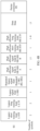
- this application provides a chip system.
- the chip system includes a processor and an interface, configured to support a communication transmission device in implementing a function in the method according to any one of the first aspect to the sixth aspect, for example, determining or processing at least one of data and information in the foregoing method.
- the chip system further includes a memory, and the memory is configured to store information and data that are necessary for the foregoing PPDU transmission apparatus.
- the chip system may include a chip, or may include a chip and another discrete device.
- this application provides a functional entity.
- the functional entity is configured to implement the method according to any one of the first aspect to the sixth aspect.
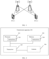
- FIG. 1 shows a structure of a network used in a data transmission method in this application.
- FIG. 1 is a schematic diagram of the structure of the network according to an embodiment of this application.
- the structure of the network may include one or more access point (access point, AP) stations and one or more non-access-point stations (none-access-point stations, non-AP STAs).
- access point station is referred to as an access point (AP)
- non-access-point station is referred to as a station (STA) in this specification.
- APs are, for example, an AP 1 and an AP 2 in FIG. 1
- STAs are, for example, a STA 1, a STA 2, and a STA 3 in FIG. 1 .
- the access point may be an access point for a terminal device (for example, a mobile phone) to access a wired (or wireless) network, and is mainly deployed at home, in a building, and in a park. A typical coverage radius is tens of meters to hundreds meters. Certainly, the access point may alternatively be deployed outdoors.
- the access point is equivalent to a bridge that connects a wired network and a wireless network.
- a main function of the access point is to connect various wireless network clients together and then connect the wireless network to an Ethernet.
- the access point may be a terminal device (for example, a mobile phone) or a network device (for example, a router) with a wireless fidelity (wireless fidelity, Wi-Fi) chip.
- the access point may be a device that supports the 802.11be standard.
- the access point may be a device that supports a plurality of wireless local area network (wireless local area network, WLAN) standards of the 802.11 family such as 802.11ax, 802.11ac, 802.11n, 802.11g, 802.11b, and 802.11a.
- the access point in this application may be a high efficient (high efficient, HE) AP or an extremely high throughput (extremely high throughput, EHT) AP, or may be an access point applicable to a future Wi-Fi standard.
- the access point may include a processor and a transceiver.
- the processor is configured to control and manage an action of the access point, and the transceiver is configured to receive or send information.
- the station may be a wireless communication chip, a wireless sensor, a wireless communication terminal, or the like, and may also be referred to as a user.
- the station may be a mobile phone supporting a Wi-Fi communication function, a tablet computer supporting a Wi-Fi communication function, a set-top box supporting a Wi-Fi communication function, a smart television supporting a Wi-Fi communication function, an intelligent wearable device supporting a Wi-Fi communication function, a vehicle-mounted communication device supporting a Wi-Fi communication function, or a computer supporting a Wi-Fi communication function.
- the station may support the 802.11be standard.
- the station may alternatively support a plurality of wireless local area network (wireless local area network, WLAN) standards of the 802.11 family such as 802.11ax, 802.11ac, 802.11n, 802.11g, 802.11b, and 802.11a.
- WLAN wireless local area network
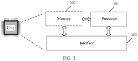
- FIG. 2 is a schematic diagram of a structure of a PPDU transmission apparatus 200 according to an embodiment of this application.
- the transmission apparatus 200 may include a processor 201 and a transceiver 205, and optionally further includes a memory 202.
- the memory 202 may store a computer program, software code, or an instruction 204, where the computer program, the software code, or the instruction 204 may also be referred to as firmware.
- the processor 201 may control a MAC layer and a PHY layer by running a computer program, software code, or an instruction 203 in the processor 201, or by invoking the computer program, the software code, or the instruction 204 stored in the memory 202, to implement the data transmission method provided in the following embodiments of this application.
- the processor 201 may be a central processing unit (central processing unit, CPU), and the memory 202 may be, for example, a read-only memory (read-only memory, ROM), or a random access memory (random access memory, RAM).
- CPU central processing unit
- RAM random access memory
- the processor 201 and the transceiver 205 described in this application may be implemented in an integrated circuit (integrated circuit, IC), an analog IC, a radio frequency integrated circuit RFIC, a mixed-signal IC, an application-specific integrated circuit (application-specific integrated circuit, ASIC), a printed circuit board (printed circuit board, PCB), an electronic device, or the like.
- integrated circuit integrated circuit, IC
- analog IC analog IC
- radio frequency integrated circuit RFIC radio frequency integrated circuit
- RFIC radio frequency integrated circuit
- mixed-signal IC mixed-signal IC
- ASIC application-specific integrated circuit
- PCB printed circuit board
- an electronic device or the like.
- the transmission apparatus 200 may further include an antenna 206.
- the modules included in the transmission apparatus 200 are merely examples for description. This is not limited in this application.
- the transmission apparatus 200 described in the foregoing embodiment may be an access point or a station.
- the scope of the transmission apparatus described in this application is not limited thereto, and the structure of the transmission apparatus may not be limited in FIG. 2 .
- the transmission apparatus may be an independent device, or may be a part of a relatively large device.
- the transmission apparatus may be implemented in the following form: (1) an independent integrated circuit IC, a chip, a chip system, or a subsystem; (2) a set including one or more ICs, where optionally, the set of ICs may also include a storage component for storing data and instructions; (3) a module that can be embedded in another device; (4) a receiver, an intelligent terminal, a wireless device, a handheld device, a mobile unit, a vehicle-mounted device, a cloud device, an artificial intelligence device, or the like; or (5) others.
- Embodiments of this application do not limit the protection scope and applicability of the claims. Persons skilled in the art may adaptively change functions and deployments of elements in this application, or omit, replace, or add various processes or components as appropriate without departing from the scope of embodiments of this application.
- 802.11ax different PPDUs are separately designed for scenarios in which a network device performs single user (single user, SU) transmission and multiple user (multiple user, MU) transmission.
- FIG. 4A is a schematic diagram of a structure of an HE SU PPDU in 802.11ax.
- the HE SU PPDU includes a legacy short training field (legacy short training field, L-STF), a legacy long training field (legacy long training field, L-LTF), a legacy signal field (legacy signal field, L-SIG), a repeated legacy signal field (RL-SIG), a high efficient signal field A (HE-SIG A), a high efficient short training field (HE-STF), a high efficient long training field (HE-LTF), a data (data) field, and a packet extension (packet extension, PE) field.
- the L-SIG and the RL-SIG have a same length, and duration of fields that follow the L-SIG and that are indicated by the L-SIG is not an integer multiple of 3.
- FIG. 4B is a schematic diagram of a structure of an HE MU PPDU in 802.11ax.
- the HE MU PPDU includes an L-STF, an L-LTF, an L-SIG, an RL-SIG, an HE-SIG A, an HE-SIG B, an HE-STF, an HE-LTF, a data field, and a PE field.
- the L-SIG and the RL-SIG have a same length, and duration of fields that follow the L-SIG and that are indicated by the L-SIG is not an integer multiple of 3.
- FIG. 4C is a schematic diagram of a structure of an HE NDP in 802.11ax.
- the HE NDP includes an L-STF, an L-LTF, an L-SIG, an RL-SIG, an HE-SIG A, an HE-STF, an HE-LTF, and a PE field.
- the PPDU is classified into an NDP and a PPDU including a data field.
- the NDP is a PPDU that does not include the data field, and may be understood as a special PPDU.
- a Bfee When receiving an NDP, a Bfee first determines, based on an L-SIG and an RL-SIG, a specific generation of a standard to which a version of a received PPDU belongs, and then calculates that a number of symbols of a data field is 0, to determine that the received PPDU is the NDP.
- the Bfee detects the L-SIG and the RL-SIG, and if the two fields are the same and duration of fields that follow the L-SIG and that are indicated by the L-SIG is not a multiple of 3, the Bfee determines that the received signal is an HE PPDU.
- the L-SIG includes length indication information, indicating a sum of lengths of all fields following the L-SIG in terms of time. Lengths of an HE-SIG-A and an HE-STF are fixed.
- the Bfee can calculate, based on the lengths of the HE-SIG-A and the HE-STF, a number of HE-LTFs indicated by the HE-SIG-A, a length of a guard interval, a size of the HE-LTF, and a packet extension related parameter, that a length of the data field is 0, to determine that the received HE PPDU is an HE NDP.
- FIG. 5 is a schematic diagram of a structure of a possible EHT PPDU.
- the EHT PPDU includes an L-STF, an L-LTF, an L-SIG, an RL-SIG, a U-SIG, an EHT-SIG, an EHT-STF, an EHT-LTF, a data field, and a PE field.
- the L-SIG and the RL-SIG have a same length, and duration of fields that follow the L-SIG and that are indicated by the L-SIG is an integer multiple of 3.
- the U-SIG and the EHT-SIG are signal fields.
- the U-SIG is used to carry some common information, for example, information indicating a PPDU version, information indicating uplink/downlink, information indicating a frequency domain bandwidth of the PPDU, and puncture indication information.
- the EHT-SIG includes information indicating resource allocation, information indicating data demodulation, and the like.
- the U-SIG includes a physical layer version identifier (version identifier) indication subfield, an uplink/a downlink (uplink/downlink, UL/DL) indication subfield, a basic service set color (basic service set color, BSS color) subfield, a transmit opportunity (transmit opportunity, TXOP) subfield, a bandwidth (bandwidth) and preamble puncture (preamble puncture) indication subfield, a PPDU format (PPDU format) subfield, a space-time block coding (space-time block coding, STBC) subfield, a spatial reuse (spatial reuse) indication subfield, a guard interval (guard interval, GI) and EHT-LT size (EHT-LTF size) subfield, a low density parity check extra symbol segment (low density parity check extra symbol segment, LDPC extra symbol segment) subfield, a pre-forward error correction padding factor (Pre-
- version identifier version identifier
- B0-B2 (U-SIG-1) Physical layer version identifier (version identifier) B3 Uplink/downlink (uplink/downlink, UL/DL) B4-B9 Basic service set color (basic service set color, BSS color) B10-B16 Transmit opportunity (transmit opportunity, TXOP) B17-22 Bandwidth (bandwidth) and preamble puncture (preamble puncture) B23-B24 PPDU format (PPDU format) B25 Space-time block coding (space-time block coding, STBC) B0-B1 (U-SIG-2) Spatial reuse (spatial reuse) B2-B3 Guard interval (guard interval, GI) and EHT-LTF size (EHT-LTF size) B4 Low density parity check extra symbol segment (LDPC extra symbol segment) B5-B6 Pre-forward error correction padding factor (Pre-FEC padding factor) B7 Packet extension disambiguity (packet extension disambiguity, PE disambiguity) B8-B12 Number of
- the physical layer version indication subfield is used to indicate a generation of the PPDU.
- the uplink/downlink indication subfield is used to indicate uplink or downlink.
- the BSS color subfield indicates a color identifier of a BSS in which a Bfer is located.
- the bandwidth and preamble puncture indication subfield indicates a bandwidth and preamble puncture information of a data packet.
- the PPDU format subfield is used to indicate a PPDU format.
- the STBC subfield indicates whether STBC is used for a data part.
- the low density parity check extra symbol segment subfield indicates whether an extra symbol segment is transmitted after LDPC coding is used.
- the pre-forward error correction padding factor subfield indicates a pre-forward error correction padding factor.
- the packet extension disambiguity subfield indicates whether packet extension is ambiguous.
- the subfield indicating the number of EHT-SIG symbols or MU-MIMO users indicates the number of EHT-SIG symbols or the number of MU-MIMO users.
- the EHT-SIG MCS and DCM subfield indicates an EHT-SIG MCS and whether DCM is used.
- the CRC is used to verify information.
- the tail bit is used to end coding.
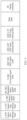
- Table 2 shows a possible structure of an EHT-SIG of an EHT PPDU including a data field.
- the EHT-SIG of the EHT PPDU includes a number of EHT-LTF symbols, midamble periodicity and doppler (number of EHT-LTF symbols, midamble periodicity and doppler) subfield, a preamble puncture (preamble puncture) indication subfield, a cyclic redundancy code (CRC), a tail bit (tail), a station identification information subfield, a number of space-time streams (number of space-time streams, NSTS) subfield, a coding (coding) subfield, a modulation and coding scheme (modulation and coding scheme, MCS) subfield, a beam change (beam change) subfield, a beamformed (beamformed) subfield, a CRC, and a tail bit.
- CRC cyclic redundancy code
- a number of bits of each subfield in Table 2 is a number of information bits before coding.
- Table 2 Bit Subfield B0-B3 Number of EHT-LTF symbols, midamble periodicity and doppler (number of EHT-LTF symbols, midamble periodicity and doppler) B4-B11 Preamble puncture (preamble puncture) indication B12-B15 Cyclic redundancy code (CRC) B16-B21 Tail bit (tail) B22-B32 Station identification information B33-B36 Number of space-time streams (number of space-time streams, NSTS) B37 Coding (coding) B38-B41 Modulation and coding scheme (modulation and coding scheme, MCS) B42 Beam change (beam change) B43 Beamformed (beamformed) B44-B47 Cyclic redundancy code (cyclic redundancy code, CRC) B48-B53 Tail bit (tail)
- CRC Cyclic redundancy code
- the number of EHT-LTF symbols, midamble periodicity and doppler subfield is used to indicate a number of EHT-LTF symbols, a midamble periodicity, and doppler.
- the number of EHT-LTF symbols, midamble periodicity and doppler subfield may be understood as a subfield indicating the number of EHT-LTF symbols.
- the preamble puncture indication subfield is used to indicate a preamble puncture mode.
- the station identification information subfield is used to indicate an association identifier (association identifier, AID).
- the coding subfield indicates a specific coding mode.
- the modulation and coding scheme subfield indicates a modulation and coding scheme of a data part.
- the beam change subfield indicates whether a beam change is applied.
- the beamformed subfield indicates whether beamforming is used.
- the EHT-SIG of the EHT PPDU includes a common field and a user-specific field.
- the user-specific field includes one or more user fields.
- the number of EHT-LTF symbols, midamble periodicity and doppler subfield, the preamble puncture indication subfield, the cyclic redundancy code, and the tail bit that correspond to B0 to B21 are common fields.
- the station identification information subfield, the number of space-time streams subfield, the coding subfield, the modulation and coding scheme subfield, the beam change subfield, the beamformed subfield, the CRC, and the tail bit that correspond to B22 and bits after B22 are user-specific fields.
- the station identification information subfield, the number of space-time streams subfield, the coding subfield, the modulation and coding scheme subfield, the beam change subfield, the beamformed subfield are a group of user fields.
- two user fields form a group, and every two user fields are followed by a CRC and a tail field. If a number of user fields is an odd number, the last user field forms a group, and the last user field is followed by a CRC and a tail field.
- the number of user fields is 1, and in this case, a number of EHT-SIG symbols is the smallest.
- a number of EHT-SIG symbols obtained through coding is 2.
- the number of EHT-SIG symbols is greater than or equal to 2.
- 802.11be provides only the structure of the EHT PPDU including the data field shown in FIG. 5 , and does not involve a structure of an EHT PPDU not including a data field, that is, does not provide an EHT NDP that satisfies the 802.11be standard. In this way, an AP and a STA cannot perform NDP measurement to obtain channel state information.
- this application provides structures of some NDPs used for a standard after 802.11ax.
- a Bfee can perform channel estimation based on an NDP to feed back a beamforming report.
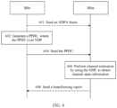
- FIG. 6 is a schematic flowchart of a PPDU transmission method according to an embodiment of this application. The method may include the following steps.
- a Bfer generates a PPDU.
- the PPDU is an NDP used for a standard after 802.11ax, and does not include a data field.
- the NDP is used by a Bfee to perform channel sounding.
- the channel sounding in this application may also be referred to as channel measurement or channel estimation.
- a second type of NDP provided in this embodiment of this application includes an EHT-SIG, a number of EHT-SIG symbols is 1, a modulation scheme used for the EHT-SIG is BPSK, and a modulation code rate used for the EHT-SIG is a code rate of 1/2.
- the number of EHT-SIG symbols is smaller, so that overheads required for transmitting the NDP can be reduced.
- a third type of NDP provided in this embodiment of this application includes an AID subfield, and the AID subfield is used to indicate information related to a user of the NDP.
- the Bfee that receives the NDP can determine, based on an AID in the EHT-SIG of the NDP, the information related to the user of the NDP, to accurately determine whether the Bfee is a user that needs to perform channel sounding and feed back a beamforming report.
- the Bfee receives the PPDU.
- the Bfee performs channel estimation by using the NDP to obtain channel state information.
- the method may further include step 608:
- the Bfee may send a beamforming report including the channel state information to the Bfer.
- the method further includes: 601:
- the Bfer sends an NDPA frame, where the NDPA frame may include a station information field, and the station information field includes an AID subfield used to indicate an AID of a station that needs to perform channel sounding and feed back a beamforming report.
- the Bfee can determine, based on the AID subfield in the NDPA frame, whether the Bfee needs to obtain channel state information. If yes, the Bfee may obtain, by using the NDP and based on partial bandwidth information indicated in the NDPA frame, channel state information within a frequency range corresponding to the partial bandwidth information.
- the first type of NDP provided in this embodiment of this application includes a U-SIG, and the U-SIG includes a subfield indicating that the PPDU is the NDP.
- the Bfee that receives the NDP can determine, based on the subfield, in the U-SIG, indicating that the PPDU is the NDP, that the PPDU is the NDP, so that the Bfee can prepare in advance a procedure of calculating the channel state information, to obtain longer processing time, and does not need to determine, after calculating that a length of a data part of the PPDU is 0, that the PPDU is the NDP.
- the NDP helps improve the efficiency of receiving the NDP by the Bfee.
- the U-SIG may include at least one of an NDP indication subfield, a PPDU format subfield, or a subfield indicating a number of EHT-SIG symbols.
- the subfield indicating that the PPDU is the NDP is the NDP indication subfield, the PPDU format subfield, or the subfield indicating the number of EHT-SIG symbols, in the U-SIG.
- the U-SIG includes the NDP indication subfield, the PPDU format subfield, or the subfield indicating the number of EHT-SIG symbols. Any one of the NDP indication subfield, the PPDU format subfield, or the subfield indicating the number of EHT-SIG symbols is the subfield indicating that the PPDU is the NDP.
- the U-SIG includes the NDP indication subfield and the PPDU format subfield, where either of the NDP indication subfield and the PPDU format subfield is the subfield indicating that the PPDU is the NDP; the U-SIG includes the PPDU format subfield and the subfield indicating the number of EHT-SIG symbols, where either of the PPDU format subfield and the subfield indicating the number of EHT-SIG symbols is the subfield indicating that the PPDU is the NDP; or the U-SIG includes the NDP indication subfield and the subfield indicating the number of EHT-SIG symbols, where either of the NDP indication subfield and the subfield indicating the number of EHT-SIG symbols is the subfield indicating that the PPDU is the NDP.
- the subfield indicating the number of EHT-SIG symbols may be, but is not limited to, a subfield indicating a number of EHT-SIG symbols or MU-MIMO users, or a number of EHT-SIG symbols subfield that is only used to indicate the number of EHT-SIG symbols.
- the subfield indicating the number of EHT-SIG symbols may indicate, for example, that the number of EHT-SIG symbols is a specified value, to indicate that the PPDU is the NDP.
- the subfield indicating the number of EHT-SIG symbols may indicate, for example, that the number of EHT-SIG symbols is 0, to indicate that the PPDU is the NDP.
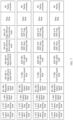
- FIG. 7 is a schematic diagram of structures of PPDUs transmitted on channels in an aggregated PPDU transmission scenario.
- Four different channels in frequency domain are respectively used to transmit an HE MU PPDU including a data field and three EHT PPDUs, where each of the three EHT PPDU includes a data field.
- the HE MU PPDU including the data field does not include a U-SIG or an EHT-SIG, but includes an HE-SIG A and an HE-SIG B.
- Positions and numbers of symbols of the HE-SIG A and the HE-SIG B in the HE MU PPDU including the data field are the same as positions and numbers of symbols of the U-SIG and the EHT-SIG. In this way, it can be ensured that symbols of the PPDUs transmitted on all the channels are aligned, so that out-of-band interference between different frequency bands is avoided.
- an HE NDP includes only an HE-SIG A having two symbols, but does not include an HE-SIG B. If a corresponding EHT NDP is designed based on a format of the EHT PPDU including the data field shown in FIG. 5 , the EHT NDP includes the EHT-SIG.
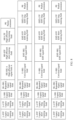
- an aggregated PPDU structure shown in FIG. 8 if hybrid transmission is performed on an HE NDP and an EHT NDP that is designed based on the format of the EHT PPDU including the data field shown in FIG. 5 , symbols of the PPDUs transmitted on all the channels are not aligned, causing out-of-band interference between different frequency bands.
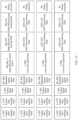
- FIG. 9 is a schematic diagram of a structure of an NDP according to an embodiment of this application.
- the NDP further includes an EHT-STF adjacent to and following the U-SIG.
- the EHT-STF closely follows the U-SIG.
- the NDP does not include an EHT-SIG.
- an EHT NDP uses the structure of the first type of NDP in this application. This helps implement symbol alignment between the EHT NDP and an HE NDP.
- the first type of NDP in this application may further include an L-STF, an L-LTF, an L-SIG, an RL-SIG, an EHT-STF, an EHT-LTF, and a PE field.
- the L-STF, the L-LTF, and the L-SIG are used to ensure coexistence between a new device and a conventional device.
- the L-SIG includes a field indicating a length, and can indicate a number of symbols in each of fields following the L-SIG.
- the RL-SIG is used to enhance reliability of a legacy signal field.
- the EHT-STF is used for automatic gain control on subsequent fields.
- the EHT-LTF is used for channel estimation.
- the first type of NDP in this application does not include the EHT-SIG.
- the U-SIG may not indicate the number of EHT-SIG symbols or an MCS, and does not need to indicate a coding-related indication, for example, an LDPC extra symbol segment indication.
- a packet extension indication may use a fixed value, and therefore does not need to be indicated.
- the U-SIG may not include the subfield indicating the number of EHT-SIG symbols, an MCS subfield, a low density parity check extra symbol segment subfield, or a packet extension disambiguity subfield.
- the U-SIG may alternatively include the subfield indicating the number of EHT-SIG symbols.
- the subfield indicating the number of EHT-SIG symbols indicates that the number of EHT-SIG symbols is a specified value, to indicate that the PPDU is the NDP.
- the U-SIG further includes at least one of a number of spatial streams (number of spatial streams, NSS) subfield and the subfield indicating the number of EHT-LTF symbols.
- the NSS subfield and/or the subfield indicating the number of EHT-LTF symbols indicate/indicates an NSS and the number of EHT-LTF symbols.
- the subfield indicating the number of EHT-LTF symbols may be, for example, a number of EHT-LTF symbols, midamble and doppler subfield; or may be a number of EHT-LTF symbols subfield that individually indicates the number of EHT-LTF symbols.
- Table 4 Bit Subfield B0-B3 Number of EHT-LTF symbols, midamble periodicity and doppler (number of EHT-LTF symbols, midamble periodicity and doppler) B4-B11 Preamble puncture (preamble puncture) B12-B15 Number of space-time streams (number of space-time streams, NSTS) B16-B19 CRC B20-B25 Tail bit (tail)
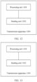
- FIG. 12 is a schematic diagram of modules of a transmission apparatus 1200 according to an embodiment of this application.
- the transmission apparatus 1200 includes a processing unit 1201 and a sending unit 1202.
- a Bfee that receives the NDP can determine, based on the subfield, in the U-SIG, indicating that the PPDU is the NDP, that the PPDU is the NDP, so that the Bfee can prepare in advance a procedure of calculating channel state information, to obtain longer processing time, and does not need to determine, after calculating that a length of a data part of the PPDU is 0, that the PPDU is the NDP.
- the NDP helps improve efficiency of receiving the NDP by the Bfee.
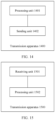
- FIG. 13 is a schematic diagram of modules of a transmission apparatus according to an embodiment of this application.
- the transmission apparatus 1300 includes a processing unit 1301 and a sending unit 1302.
- the processing unit 1301 is configured to generate a PPDU, where the PPDU is an NDP, the PPDU includes an extremely high throughput-signal field EHT-SIG, a number of EHT-SIG symbols is 1, and the EHT-SIG is modulated by using BPSK and a code rate of 1/2.
- the sending unit 1302 is configured to send the PPDU.
- the transmission apparatus 1300 may be understood as a Bfer.
- the transmission apparatus 1300 may be, for example, an access point or a station. Alternatively, the transmission apparatus is deployed at an access point or a station.
- the processing unit 1301 of the transmission apparatus 1300 may be a processor, and the sending unit 1302 of the transmission apparatus 1300 may be a transceiver.
- the subfield indicating the number of EHT-SIG symbols indicates that the number of EHT-SIG symbols is 1
- the U-SIG further includes a modulation and coding scheme MCS subfield
- the MCS subfield indicates that the EHT-SIG is modulated by using the BPSK and the code rate of 1/2.
- an NDP indication subfield or a PPDU format subfield in the U-SIG indicates that the PPDU is in an uncompressed mode.
- a number of space-time streams subfield and/or a subfield indicating a number of EHT-LTF symbols in the EHT-SIG indicate/indicates a number of space-time streams and the number of EHT-LTF symbols.
- FIG. 14 is a schematic diagram of modules of a transmission apparatus according to an embodiment of this application.
- the transmission apparatus 1400 includes a processing unit 1401 and a sending unit 1402.
- the processing unit 1401 is configured to generate a PPDU, where the PPDU is an NDP, the PPDU includes an EHT-SIG, the EHT-SIG includes an AID subfield indicating an association identifier AID, and the AID is used to indicate information related to a user of the NDP.
- the sending unit 1402 is configured to send the PPDU.
- a Bfee can determine, based on the AID in the EHT-SIG of the NDP, the information related to the user of the NDP. In this way, the Bfee can accurately determine whether the Bfee is a user that needs to perform channel sounding and feed back a beamforming report.
- the transmission apparatus 1400 may be understood as a Bfer.
- the transmission apparatus 1400 may be, for example, an access point or a station. Alternatively, the transmission apparatus is deployed at an access point or a station.
- the processing unit 1401 of the transmission apparatus 1400 may be a processor, and the sending unit 1402 of the transmission apparatus 1400 may be a transceiver.
- the AID indicated by the AID subfield is an AID of the station.
- the AID indicated by the user field is 0, indicating that the NDP is sent through broadcast.
- the AID indicated by the AID subfield is a specified value.
- the PPDU further includes a U-SIG, the U-SIG includes a format subfield and/or a compressed subfield, and the format subfield or the compressed subfield indicates that the PPDU is the NDP.
- the PPDU further includes a U-SIG and an EHT-LTF
- the U-SIG includes a number of space-time streams subfield that indicates a number of space-time streams
- a number of EHT-LTFs is greater than the number of space-time streams.
- FIG. 15 is a schematic diagram of modules of a transmission apparatus according to an embodiment of this application.
- the transmission apparatus 1500 includes a receiving unit 1501 and a processing unit 1502.
- the receiving unit 1501 is configured to receive a PPDU, where the PPDU is an NDP, the PPDU includes a universal signal field U-SIG, and the U-SIG includes a subfield indicating that the PPDU is the null data packet NDP.
- the processing unit 1502 is configured to perform channel estimation by using the NDP.
- a Bfee that receives the NDP can determine, based on the subfield, in the U-SIG, indicating that the PPDU is the NDP, that the PPDU is the NDP, so that the Bfee can prepare in advance a procedure of calculating channel state information, to obtain longer processing time, and does not need to determine, after calculating that a length of a data part of the PPDU is 0, that the PPDU is the NDP.
- the NDP helps improve efficiency of receiving the NDP by the Bfee.
- the transmission apparatus 1500 may be understood as the Bfee.
- the transmission apparatus 1500 may be, for example, a station or an access point. Alternatively, the transmission apparatus 1500 is deployed at a station or an access point.
- the processing unit 1502 of the transmission apparatus 1500 may be a processor, and the receiving unit 1501 of the transmission apparatus 1500 may be a transceiver.
- the subfield indicating that the PPDU is the NDP is an NDP indication subfield, a PPDU format subfield, or a subfield indicating a number of EHT-SIG symbols, in the U-SIG.
Landscapes
- Engineering & Computer Science (AREA)
- Signal Processing (AREA)
- Computer Networks & Wireless Communication (AREA)
- Power Engineering (AREA)
- Quality & Reliability (AREA)
- Mobile Radio Communication Systems (AREA)
- Transition And Organic Metals Composition Catalysts For Addition Polymerization (AREA)
- Addition Polymer Or Copolymer, Post-Treatments, Or Chemical Modifications (AREA)
Claims (9)
- PPDU-Übertragungsverfahren im Rahmen des Standards 802.11be, umfassend:Erzeugen (602) einer Protokolldateneinheit einer physikalischen Schicht, PPDU, wobei die PPDU ein Nulldatenpaket, NDP, ist, die PPDU ein Feld für ein Signal mit extrem hohem Durchsatz, EHT-SIG-Feld, umfasst, eine Anzahl von EHT-SIG-Symbolen 1 ist und das EHT-SIG-Feld unter Verwendung von binärer Phasenumtastung, BPSK, und einer Coderate von 1/2 moduliert ist; wobei die PPDU ferner ein Feld für ein universelles Signal, U-SIG-Feld, umfasst, das U-SIG-Feld ein Unterfeld umfasst, das anzeigt, dass die Anzahl der EHT-SIG-Symbole 1 ist; wobei das U-SIG-Feld ferner ein Modulations- und Codierschema-Unterfeld, MCS-Unterfeld, umfasst und das MCS-Unterfeld anzeigt, dass das EHT-SIG-Feld unter Verwendung der BPSK und der Coderate von 1/2 moduliert ist; undSenden (604) der PPDU.
- Verfahren nach Anspruch 1, wobei ein NDP-Anzeigeunterfeld oder ein PPDU-Formatunterfeld in dem U-SIG-Feld anzeigt, dass sich die PPDU in einem unkomprimierten Modus befindet.
- Verfahren nach Anspruch 1 oder 2, wobei das EHT-SIG-Feld ferner Folgendes umfasst: ein Unterfeld, das eine Anzahl von Space-Streams anzeigt, und ein Unterfeld, das eine Anzahl von EHT-LTF-Symbolen anzeigt.
- PPDU-Übertragungsverfahren im Rahmen des Standards 802.11be, umfassend:Empfangen (604) einer Protokolldateneinheit einer physikalischen Schicht, PPDU, wobei die PPDU ein Feld für ein Signal mit extrem hohem Durchsatz, EHT-SIG-Feld, umfasst; wobei die PPDU ferner ein Feld für ein universelles Signal, U-SIG-Feld, umfasst, das U-SIG-Feld ein Unterfeld umfasst, das anzeigt, dass eine Anzahl von EHT-SIG-Symbolen 1 ist, wobei das U-SIG-Feld ferner ein Modulations- und Codierschema-Unterfeld, MCS-Unterfeld, umfasst und das MCS-Unterfeld anzeigt, dass das EHT-SIG-Feld unter Verwendung der BPSK und der Coderate von 1/2 moduliert ist; undIdentifizieren, dass die PPDU ein Null-Datenpaket, NDP, ist sowohl gemäß dem Unterfeld, das angibt, dass die Anzahl der EHT-SIG-Symbole 1 ist, als auch gemäß dem MCS-Unterfeld, das angibt, dass das EHT-SIG-Feld unter Verwendung von binärer Phasenumtastung, BPSK, und einer Coderate von 1/2 moduliert wird; undDurchführen (606) einer Kanalschätzung unter Verwendung des NDP.
- Verfahren nach Anspruch 4, wobei das Verfahren ferner Folgendes umfasst:
Identifizieren, dass sich die PPDU in einem unkomprimierten Modus befindet, gemäß einer Anzeige eines NDP-Anzeigeunterfelds oder eines PPDU-Formatunterfelds in dem U-SIG-Feld. - Verfahren nach Anspruch 4 oder 5, wobei das EHT-SIG-Feld ferner Folgendes umfasst: ein Unterfeld, das eine Anzahl von Space-Streams anzeigt, und ein Unterfeld, das eine Anzahl von EHT-LTF-Symbolen anzeigt.
- Übertragungsvorrichtung für eine Protokolldateneinheit einer physikalischen Schicht, PPDU-Übertragungsvorrichtung, die dazu konfiguriert ist, das Verfahren nach einem der Ansprüche 1 bis 3 durchzuführen.
- Übertragungsvorrichtung für eine Protokolldateneinheit einer physikalischen Schicht, PPDU-Übertragungsvorrichtung, die dazu konfiguriert ist, das Verfahren nach einem der Ansprüche 4 bis 6 durchzuführen.
- Computerlesbares Speichermedium, wobei das computerlesbare Speichermedium Computeranweisungen speichert; und wenn die Computeranweisungen durch einen Prozessor ausgeführt werden, Durchführen des Verfahrens nach einem der Ansprüche 1 bis 3 oder des Verfahrens nach einem der Ansprüche 4 bis 6.
Priority Applications (1)
| Application Number | Priority Date | Filing Date | Title |
|---|---|---|---|
| EP25173147.7A EP4614915A3 (de) | 2020-06-05 | 2021-05-27 | Ppdu-übertragungsverfahren und zugehörige vorrichtung |
Applications Claiming Priority (2)
| Application Number | Priority Date | Filing Date | Title |
|---|---|---|---|
| CN202010506948.XA CN113765831A (zh) | 2020-06-05 | 2020-06-05 | Ppdu的传输方法及相关装置 |
| PCT/CN2021/096553 WO2021244405A1 (zh) | 2020-06-05 | 2021-05-27 | Ppdu的传输方法及相关装置 |
Related Child Applications (2)
| Application Number | Title | Priority Date | Filing Date |
|---|---|---|---|
| EP25173147.7A Division-Into EP4614915A3 (de) | 2020-06-05 | 2021-05-27 | Ppdu-übertragungsverfahren und zugehörige vorrichtung |
| EP25173147.7A Division EP4614915A3 (de) | 2020-06-05 | 2021-05-27 | Ppdu-übertragungsverfahren und zugehörige vorrichtung |
Publications (4)
| Publication Number | Publication Date |
|---|---|
| EP4152706A1 EP4152706A1 (de) | 2023-03-22 |
| EP4152706A4 EP4152706A4 (de) | 2023-11-01 |
| EP4152706C0 EP4152706C0 (de) | 2025-07-09 |
| EP4152706B1 true EP4152706B1 (de) | 2025-07-09 |
Family
ID=78785147
Family Applications (2)
| Application Number | Title | Priority Date | Filing Date |
|---|---|---|---|
| EP25173147.7A Pending EP4614915A3 (de) | 2020-06-05 | 2021-05-27 | Ppdu-übertragungsverfahren und zugehörige vorrichtung |
| EP21818276.4A Active EP4152706B1 (de) | 2020-06-05 | 2021-05-27 | Ppdu-übertragungsverfahren und zugehörige vorrichtung |
Family Applications Before (1)
| Application Number | Title | Priority Date | Filing Date |
|---|---|---|---|
| EP25173147.7A Pending EP4614915A3 (de) | 2020-06-05 | 2021-05-27 | Ppdu-übertragungsverfahren und zugehörige vorrichtung |
Country Status (11)
| Country | Link |
|---|---|
| US (2) | US12212438B2 (de) |
| EP (2) | EP4614915A3 (de) |
| JP (2) | JP7556055B2 (de) |
| KR (3) | KR20250038811A (de) |
| CN (3) | CN113765831A (de) |
| AU (1) | AU2021284567B2 (de) |
| BR (1) | BR112022024725A2 (de) |
| CA (1) | CA3186283A1 (de) |
| ES (1) | ES3040990T3 (de) |
| MX (1) | MX2022015462A (de) |
| WO (1) | WO2021244405A1 (de) |
Families Citing this family (5)
| Publication number | Priority date | Publication date | Assignee | Title |
|---|---|---|---|---|
| CN116980986B (zh) * | 2020-04-30 | 2024-07-19 | 华为技术有限公司 | 一种应用于无线局域网的带宽指示方法及通信装置 |
| US20220345904A1 (en) * | 2021-04-22 | 2022-10-27 | Samsung Electronics Co., Ltd. | Apparatus and method for channel sounding |
| EP4236099A1 (de) * | 2022-02-24 | 2023-08-30 | Samsung Electronics Co., Ltd. | Vorrichtung und verfahren zur kanalmessung |
| CN115051764B (zh) * | 2022-06-02 | 2023-10-10 | 恒玄科技(北京)有限公司 | 用于WLAN 11ax系统发射通道质量状况监控的系统和方法 |
| CN119276412A (zh) * | 2023-07-07 | 2025-01-07 | 华为技术有限公司 | 调制编码策略指示方法和相应装置 |
Family Cites Families (21)
| Publication number | Priority date | Publication date | Assignee | Title |
|---|---|---|---|---|
| CN101848063B (zh) * | 2010-05-21 | 2016-06-08 | 北京新岸线移动多媒体技术有限公司 | 支持子信道调制编码的数据传输方法及无线局域网系统 |
| WO2013085289A1 (ko) * | 2011-12-06 | 2013-06-13 | 엘지전자 주식회사 | 무선랜 시스템에서 채널 사운딩 수행 방법 및 이를 지원하는 장치 |
| EP2947946B1 (de) * | 2013-01-16 | 2018-01-03 | LG Electronics Inc. | Verfahren zur durchführung eines backoff in einem wlan-system und vorrichtung dafür |
| WO2016028124A1 (ko) * | 2014-08-21 | 2016-02-25 | 엘지전자(주) | 무선 통신 시스템에서 데이터 전송 방법 및 이를 위한 장치 |
| JP6430635B2 (ja) * | 2014-10-01 | 2018-11-28 | エルジー エレクトロニクス インコーポレイティド | 無線通信システムにおけるデータ送信方法及びこのための装置 |
| US10135957B2 (en) * | 2015-06-15 | 2018-11-20 | Qualcomm Incorporated | Methods and apparatus for communicating high efficiency control information |
| WO2017007266A1 (ko) * | 2015-07-07 | 2017-01-12 | 엘지전자 주식회사 | 무선랜 시스템에서 사운딩 동작 방법 및 이를 위한 장치 |
| CN106533522B (zh) * | 2015-09-10 | 2020-10-09 | 华为技术有限公司 | 一种传输信道状态信息的方法和装置 |
| US20190116513A1 (en) * | 2017-10-16 | 2019-04-18 | Qualcomm Incorporated | Extremely high throughput (eht) signal detection |
| US11272490B2 (en) * | 2018-06-01 | 2022-03-08 | Qualcomm Incorporated | Techniques for control signaling in extreme high throughput environments |
| CN116318583B (zh) * | 2018-07-09 | 2023-12-08 | 华为技术有限公司 | 一种信令字段指示方法及装置 |
| CN116405161B (zh) * | 2018-07-17 | 2024-01-16 | 华为技术有限公司 | 一种通信方法及装置 |
| US11082983B2 (en) * | 2018-09-10 | 2021-08-03 | Intel Corporation | Tone plans and preambles for extremely high throughput |
| EP4601227A3 (de) | 2018-11-08 | 2025-10-22 | InterDigital Patent Holdings, Inc. | Verfahren und vorrichtung für harq in drahtlosen netzwerken |
| US11128505B2 (en) * | 2019-02-06 | 2021-09-21 | Intel Corporation And Intel Ip Corporation | Channel width, spatial streams, and short packet signaling |
| US11564250B2 (en) * | 2019-08-09 | 2023-01-24 | Qualcomm Incorporated | Physical layer preamble and signaling for wireless communication |
| US11665574B2 (en) * | 2019-10-25 | 2023-05-30 | Qualcomm Incorporated | Physical layer preamble design for special packet types |
| US11588673B2 (en) * | 2020-01-30 | 2023-02-21 | Lg Electronics Inc. | Techniques for transmitting information related to a PPDU format in wireless local area network system |
| US11743016B2 (en) * | 2020-04-24 | 2023-08-29 | Nxp Usa, Inc. | Method and apparatus for wireless communications |
| US12177154B2 (en) * | 2020-07-30 | 2024-12-24 | Qualcomm Incorporated | Enhanced sounding packet designs |
| KR20220033966A (ko) * | 2020-09-10 | 2022-03-17 | 삼성전자주식회사 | 집성된 ppdu에 기초한 채널 사운딩을 위한 장치 및 방법 |
-
2020
- 2020-06-05 CN CN202010506948.XA patent/CN113765831A/zh active Pending
- 2020-06-05 CN CN202211656231.9A patent/CN116418457B/zh active Active
- 2020-06-05 CN CN202211212493.6A patent/CN115865571B/zh active Active
-
2021
- 2021-05-27 MX MX2022015462A patent/MX2022015462A/es unknown
- 2021-05-27 CA CA3186283A patent/CA3186283A1/en active Pending
- 2021-05-27 EP EP25173147.7A patent/EP4614915A3/de active Pending
- 2021-05-27 JP JP2022574546A patent/JP7556055B2/ja active Active
- 2021-05-27 WO PCT/CN2021/096553 patent/WO2021244405A1/zh not_active Ceased
- 2021-05-27 AU AU2021284567A patent/AU2021284567B2/en active Active
- 2021-05-27 KR KR1020257007053A patent/KR20250038811A/ko active Pending
- 2021-05-27 KR KR1020247037789A patent/KR102777774B1/ko active Active
- 2021-05-27 KR KR1020227046481A patent/KR102731349B1/ko active Active
- 2021-05-27 ES ES21818276T patent/ES3040990T3/es active Active
- 2021-05-27 EP EP21818276.4A patent/EP4152706B1/de active Active
- 2021-05-27 BR BR112022024725A patent/BR112022024725A2/pt active Search and Examination
-
2022
- 2022-12-02 US US18/074,269 patent/US12212438B2/en active Active
-
2024
- 2024-09-11 JP JP2024157194A patent/JP2024177189A/ja active Pending
- 2024-10-29 US US18/930,889 patent/US20250055728A1/en active Pending
Also Published As
| Publication number | Publication date |
|---|---|
| AU2021284567A1 (en) | 2023-01-19 |
| CN116418457B (zh) | 2024-02-13 |
| KR20230019891A (ko) | 2023-02-09 |
| JP2023532416A (ja) | 2023-07-28 |
| US12212438B2 (en) | 2025-01-28 |
| WO2021244405A1 (zh) | 2021-12-09 |
| CN116418457A (zh) | 2023-07-11 |
| BR112022024725A2 (pt) | 2023-02-28 |
| EP4152706C0 (de) | 2025-07-09 |
| CN115865571A (zh) | 2023-03-28 |
| MX2022015462A (es) | 2023-03-23 |
| JP2024177189A (ja) | 2024-12-19 |
| JP7556055B2 (ja) | 2024-09-25 |
| US20250055728A1 (en) | 2025-02-13 |
| AU2021284567B2 (en) | 2024-08-08 |
| KR20250038811A (ko) | 2025-03-19 |
| KR20240166595A (ko) | 2024-11-26 |
| KR102731349B1 (ko) | 2024-11-15 |
| CA3186283A1 (en) | 2021-12-09 |
| EP4614915A3 (de) | 2025-10-08 |
| EP4152706A1 (de) | 2023-03-22 |
| AU2024259666A1 (en) | 2024-11-21 |
| EP4614915A2 (de) | 2025-09-10 |
| ES3040990T3 (en) | 2025-11-06 |
| US20230096177A1 (en) | 2023-03-30 |
| EP4152706A4 (de) | 2023-11-01 |
| CN113765831A (zh) | 2021-12-07 |
| KR102777774B1 (ko) | 2025-03-06 |
| CN115865571B (zh) | 2024-01-05 |
Similar Documents
| Publication | Publication Date | Title |
|---|---|---|
| EP4152706B1 (de) | Ppdu-übertragungsverfahren und zugehörige vorrichtung | |
| KR101871080B1 (ko) | 중첩된 서비스 영역에서 간섭을 방지하는 방법 및 장치 | |
| US11757585B2 (en) | Data transmission method and related apparatus | |
| US11784752B2 (en) | Method and apparatus for transmitting PPDU in duplicate (DUP) mode in a wireless communication system | |
| US11843973B2 (en) | Communication apparatus, processing apparatus, communication method, and storage medium, for throughput improvement of wireless networks | |
| US20250267511A1 (en) | Communication device, communication method thereof, information processing device, control method thereof, and computer-readable storage medium | |
| US20230110435A1 (en) | Multi-resource-unit transmission indication method, and related device | |
| JP2024073555A (ja) | ヌル・データ・パケット・アナウンスメント・フレーム伝送方法及び関連装置 | |
| US20240154738A1 (en) | Communication method and apparatus | |
| EP3934319A1 (de) | Kommunikationsvorrichtung, steuerungsverfahren und programm |
Legal Events
| Date | Code | Title | Description |
|---|---|---|---|
| STAA | Information on the status of an ep patent application or granted ep patent |
Free format text: STATUS: THE INTERNATIONAL PUBLICATION HAS BEEN MADE |
|
| PUAI | Public reference made under article 153(3) epc to a published international application that has entered the european phase |
Free format text: ORIGINAL CODE: 0009012 |
|
| STAA | Information on the status of an ep patent application or granted ep patent |
Free format text: STATUS: REQUEST FOR EXAMINATION WAS MADE |
|
| 17P | Request for examination filed |
Effective date: 20221214 |
|
| AK | Designated contracting states |
Kind code of ref document: A1 Designated state(s): AL AT BE BG CH CY CZ DE DK EE ES FI FR GB GR HR HU IE IS IT LI LT LU LV MC MK MT NL NO PL PT RO RS SE SI SK SM TR |
|
| DAV | Request for validation of the european patent (deleted) | ||
| DAX | Request for extension of the european patent (deleted) | ||
| A4 | Supplementary search report drawn up and despatched |
Effective date: 20230928 |
|
| RIC1 | Information provided on ipc code assigned before grant |
Ipc: H04L 27/26 20060101ALN20230922BHEP Ipc: H04L 1/06 20060101ALN20230922BHEP Ipc: H04L 1/00 20060101ALN20230922BHEP Ipc: H04L 25/02 20060101AFI20230922BHEP |
|
| STAA | Information on the status of an ep patent application or granted ep patent |
Free format text: STATUS: EXAMINATION IS IN PROGRESS |
|
| 17Q | First examination report despatched |
Effective date: 20240711 |
|
| GRAP | Despatch of communication of intention to grant a patent |
Free format text: ORIGINAL CODE: EPIDOSNIGR1 |
|
| STAA | Information on the status of an ep patent application or granted ep patent |
Free format text: STATUS: GRANT OF PATENT IS INTENDED |
|
| RIC1 | Information provided on ipc code assigned before grant |
Ipc: H04L 27/26 20060101ALN20250109BHEP Ipc: H04L 1/06 20060101ALN20250109BHEP Ipc: H04L 1/00 20060101ALN20250109BHEP Ipc: H04L 25/02 20060101AFI20250109BHEP |
|
| INTG | Intention to grant announced |
Effective date: 20250129 |
|
| GRAS | Grant fee paid |
Free format text: ORIGINAL CODE: EPIDOSNIGR3 |
|
| GRAA | (expected) grant |
Free format text: ORIGINAL CODE: 0009210 |
|
| STAA | Information on the status of an ep patent application or granted ep patent |
Free format text: STATUS: THE PATENT HAS BEEN GRANTED |
|
| AK | Designated contracting states |
Kind code of ref document: B1 Designated state(s): AL AT BE BG CH CY CZ DE DK EE ES FI FR GB GR HR HU IE IS IT LI LT LU LV MC MK MT NL NO PL PT RO RS SE SI SK SM TR |
|
| REG | Reference to a national code |
Ref country code: GB Ref legal event code: FG4D |
|
| REG | Reference to a national code |
Ref country code: CH Ref legal event code: EP |
|
| REG | Reference to a national code |
Ref country code: IE Ref legal event code: FG4D |
|
| U01 | Request for unitary effect filed |
Effective date: 20250709 |
|
| U07 | Unitary effect registered |
Designated state(s): AT BE BG DE DK EE FI FR IT LT LU LV MT NL PT RO SE SI Effective date: 20250715 |
|
| REG | Reference to a national code |
Ref country code: ES Ref legal event code: FG2A Ref document number: 3040990 Country of ref document: ES Kind code of ref document: T3 Effective date: 20251106 |