EP4152589B1 - Photo-piezoelektrischer generator von elektrischer energie aus lichtenergie - Google Patents
Photo-piezoelektrischer generator von elektrischer energie aus lichtenergie Download PDFInfo
- Publication number
- EP4152589B1 EP4152589B1 EP21461595.7A EP21461595A EP4152589B1 EP 4152589 B1 EP4152589 B1 EP 4152589B1 EP 21461595 A EP21461595 A EP 21461595A EP 4152589 B1 EP4152589 B1 EP 4152589B1
- Authority
- EP
- European Patent Office
- Prior art keywords
- converting element
- layer
- photo
- lens
- casing
- Prior art date
- Legal status (The legal status is an assumption and is not a legal conclusion. Google has not performed a legal analysis and makes no representation as to the accuracy of the status listed.)
- Active
Links
Images





Classifications
-
- H—ELECTRICITY
- H02—GENERATION; CONVERSION OR DISTRIBUTION OF ELECTRIC POWER
- H02N—ELECTRIC MACHINES NOT OTHERWISE PROVIDED FOR
- H02N2/00—Electric machines in general using piezoelectric effect, electrostriction or magnetostriction
- H02N2/18—Electric machines in general using piezoelectric effect, electrostriction or magnetostriction producing electrical output from mechanical input, e.g. generators
-
- H—ELECTRICITY
- H10—SEMICONDUCTOR DEVICES; ELECTRIC SOLID-STATE DEVICES NOT OTHERWISE PROVIDED FOR
- H10N—ELECTRIC SOLID-STATE DEVICES NOT OTHERWISE PROVIDED FOR
- H10N30/00—Piezoelectric or electrostrictive devices
- H10N30/30—Piezoelectric or electrostrictive devices with mechanical input and electrical output, e.g. functioning as generators or sensors
- H10N30/304—Beam type
- H10N30/306—Cantilevers
Definitions
- the present invention relates to generation of electrical energy from light energy by means of a photo-piezoelectric generator.
- PCT application WO2019202620A1 discloses an energy conversion device configured to convert a light signal into an electrical signal, comprising: a substantially planar actuator element, having at least one activatable portion, said activatable portion comprising a photomobile polymeric material; a substantially planar transducer element, having at least a portion of piezoelectric material; wherein said actuator element is coupled to said transducer element so that, at a light beam incident on said photomobile polymeric material, a movement of said transducer element is activated through a movement of said activatable portion, said movement of said transducer element providing the generation of a potential difference at the terminal ends of said portion of piezoelectric material.
- Such device has a drawback that upon illumination of the layer containing the photo-mobile polymer it will bend only once and remain in the bent position until the illumination vanishes. It means that when placed under constant illumination, the device will produce only a single portion of energy by generating a single electrical pulse.
- KR101928966B1 discloses a multi-smart sensor device using multiple inputs of energy harvesting.
- the technical problem to be solved is to produce and collect electric energy based on photoelectric effect generated by light energy, piezoelectric effect by vibration, electromagnetic induction phenomenon by magnetic field change, improve reliability by multi-sensing, and increase the versatility of use through multiple sensors.
- the multi-smart sensor device includes an energy harvesting unit that produces energy based on a photoelectric effect using light energy, a piezoelectric effect associated with external force, and electromagnetic induction; a power source unit for storing and supplying energy produced through the energy harvesting unit; a sensor unit for detecting a mechanical contact, a contact by magnetic field and metal, and a posture by positional change, respectively; and a communication interface unit for transmitting detected data of the sensor unit to an external receiving apparatus.
- CN108809208B discloses a road energy collection device, which includes a base, a photovoltaic power generation module and a piezoelectric power generation module; the photovoltaic power generation module is installed on the surface of the base and is used to collect road light to generate electricity.
- CN109428515A discloses a miniature composite vibration generator that comprises a base, a shell arranged on the base and a thin film piezoelectric piece arranged in the shell, and further comprises a solar photovoltaic cell arranged on the upper surface of the shell, a circuit board arranged in the shell, and a U-shaped mass block connected with thethin film piezoelectric piece.
- the object of the invention is a photo-piezoelectric generator of electrical energy from light energy according to the appended claims.
- the converting element is adapted to perform cyclic deformation, in can operate in a sustained manner under constant illumination of the generator. Therefore, the generator does not require use of devices that would cyclically turn illumination on and off, or cyclically cover and uncover the generator.
- the elastic converting element may comprise a first layer made of a piezoelectric material and a second layer made of a photo-mobile polymer material attached thereto, wherein a first electrode layer is provided at one side of the first layer between the first layer and the second layer and a second electrode layer is provided at the other side of the first layer.
- a first electrode layer is provided at one side of the first layer between the first layer and the second layer and a second electrode layer is provided at the other side of the first layer.
- the elastic converting element can be mounted at one side to the inner wall of the casing, wherein the casing is opaque; and a lens can be provided at one side of the casing, wherein the converting element is mounted such that incident light refracted by the lens illuminates a larger area of the second layer made of the photo-mobile polymer in the first position than in the second position of the converting element. It is one of the possible configurations of the generator that allows for cyclic bending of the converting element.
- the opaqueness of the casing ensures that the photo-sensitive second layer made of the photo-mobile polymer is subject only to the light that passes through the lens.
- the inner walls of the casing can be covered by an antireflective material. This eliminates parasitic illumination of the converting element by light reflected from the inner walls. The light reflected from the inner walls might impede the dynamics and amplitude of bending of the converting element, and in the worst case - it might halt the cyclic operation.
- the piezoelectric material of the first layer contains a material that exhibits piezoelectric properties, such as zinc oxide nanowires
- the zinc oxide nanowires can be immersed in an electrical insulator.
- the advantage of using a nanostructured piezoelectric layer is the enhancement of generated piezoelectric signal compared to a bulk material.
- the nanostructured layer has a morphology of nanowires with the highest possible height to width ratio, which maximizes the generated voltage.
- the most dense possible packing of nanowires per unit area, while maintaining electrical separation ensures by the insulator layer maximizes the generated current. Both strategies (nanostructring and dense packing) directly enhance the generated power.
- the lens can be a biconvex focusing lens having a focal length selected so that the focal point of the lens lies on the second layer made of the photo-mobile polymer material when the converting element is in the first position. Placing the focal point on the layer made of a photo-mobile polymer material causes light energy to be focused on the photo-mobile polymer. Therefore, the photo-mobile polymer material is struck by higher density of electromagnetic radiation. This leads to increased amplitude and/or frequency of the bending of the converting element.
- the converting element can be mounted in a plane that is perpendicular to the optical axis of the lens.
- the lens focuses incoming light beams. Therefore, in the first position, when the converting element is undeformed, it lies in the focal point O of the lens. After bending, the converting element lies essentially outside the focal point.
- the converting element can be mounted in a plane that is oblique to the optical axis of the lens. Mounting the converting element at an oblique angle from the optical axis of the lens causes the incoming light to focus in the shape of an ellipse on the surface of the converting element. Consequently, the surface area of focus on the surface of the converting element is higher than in an embodiment in which the converting element is perpendicular to the optical axis of the lens. A larger surface area of focus causes faster isomerization of the photo-mobile material, which causes the bending of the converting element to be greater and more dynamic.
- mounting the converting element at an oblique angle from the optical axis of the lens causes the converting element to cross from illuminated to dark region and back in a more rapid manner than in an embodiment in which the converting element is perpendicular to the optical axis of the lens.
- the converting element can be rigidly and inseparably attached to the casing at its one end, while the other end of the converting element can be free. Rigid attachment of only one end of the converting element facilitates cyclic motion of the converting element between the illuminated and dark regions. Moreover, attaching only one end provides means to achieve higher bending of the other end of the converting element. Additionally, attaching only one side of the converting element minimizes the risk of the converting element halting in a midpoint between illuminated and dark regions.
- the photo-mobile polymer material of the second layer may exhibits a delay between turning on the illumination and the beginning of the bending mechanical motion.
- the delay between illumination (the beginning of light energy absorption) and deformation ensure cyclic operation of the converting element. It prevents halting of the converting element in a midpoint between illuminated and dark regions.
- the generator may further comprise a ferromagnetic mass attached to the free end of the converting element and a permanent magnet mounted on the casing such that the ferromagnetic mass interacts with the permanent magnet at a portion of the trajectory of the converting element.
- the permanent magnet and the ferromagnetic mass allows sustained operation of the generator in case the photo-mobile polymer material does not show intrinsic delay between illumination and deformation.
- Fig. 1 shows a photo-piezoelectric generator of electrical energy from light energy according to a first embodiment in a side view.
- the photo-piezoelectric generator comprises an opaque casing 10 and an elastic converting element 20 positioned within the casing 10, mounted at one side to the wall of the casing 10. Additionally, one of the walls of the casing 10 contains a lens 11.
- one end of the converting element 20 is rigidly and inseparably attached to the casing 10, while the other end of the converting element 20 is free.
- the converting element 20 is mounted in a plane that is perpendicular to the optical axis of the lens 11.
- the converting element 20 has a form a multilayer rectangular plate.
- Fig. 5 shows schematically a structure the converting element 20.
- the converting element 20 comprises a first layer 21 made of a piezoelectric material, on top of which a second layer 22 made of a photo-mobile polymer material is provided.
- a first electrode layer 23A is provided at one side of the first layer 21 (between the first layer 21 and the second layer 22) and a second electrode layer 23B is provided on the other side of the first layer 21.
- the material of the first layer 21 can be any piezoelectric material including zinc oxide ZnO nanostructures, e.g. having a form of nanowires.
- the first layer 21, between regions 21A which contain the piezoelectric material comprises regions 21B made of an electrical insulator.
- the piezoelectric components are immersed in an electrical insulator which allows for energy collection only from the top surface.
- Figs. 2A-2F show, in a cross section A-A' of Fig. 1 , subsequent steps of deformation of the converting element 20 between its first position and second position (wherein the first position can be considered as an initial position and the second position can be considered as a final position within one deformation stage).
- the converting element 20 is mounted on the casing 10 such that it can be deformed between the first position and the second position.
- incident light refracted by the lens 11 illuminates a larger area of the second layer 22 made of a photo-mobile polymer than it does in the second position.
- the lens 11 is a biconvex focusing lens having a focal length f selected so that the focal point O of the lens 11 lies on the second layer 22 when the converting element 20 is in the first position and, preferably, the focal point O lies outside the second layer 22 when the converting element 20 is in the second position.
- the converting element 20 in the first position, is essentially straight.
- the second layer 22 deforms, in particular by bending, which causes bending of all the layers that constitute the converting element 20.
- the converting element 20 in the first position (i.e. in a resting state) as shown in Fig. 2A , the converting element 20 is essentially straight.
- natural or artificial light carrying energy (hv per quantum) reaches the generator, it is focused by the lens 11 in the focal point O.
- the photo-mobile polymer in the second layer 22 interacts with the light, which after a finite period of illumination causes a mechanical stress which leads to a bending of the second layer 22, and thus the whole converting element 20.
- the bending results in a displacement of the converting element 20 to a less illuminated region of the casing 10, in particular beyond the focal point O of lens 11 ( Fig. 2C ).
- Figs. 2D, 2E This leads to dissipation of an isomerization reaction in the photo-mobile polymer layer 22 and the movement of the converting element 20 ( Figs. 2D, 2E ) back to its straight position ( Figs. 2F, 2A ).
- the converting element 20 In the straight position, the converting element 20 returns to the focal point O of the lens 11, wherein the light intensity is at its maximum and another work cycle can begin ( Figs. 2D / 4D /7D).
- the motion induced by light depicted schematically in Figs. 2A-2F , is the source of bending of the first layer 21 made of the piezoelectric material, which induces a voltage V OUT between electrodes 23A and 23B. Therefore, the generator according to the present invention utilizes the piezoelectric conversion of the cyclic mechanical bending of the photo-mobile polymer to convert light energy to mechanical energy, and in turn, to electrical energy.
- Fig. 6 shows a waveform of the generated voltage.
- the inner walls of the casing 10 are covered by an antireflective (or a light-absorbing) material 12. Consequently, light entering the interior of the casing 10 through the lens 11 is not reflected from the inner walls of the casing 10 and does not cause a secondary illumination of the converting element 20, which would lead to impeded dynamics of motion (i.e. slowing down) of the converting element 20, and consequently, halting the converting element 20 in an intermediate position. To prevent this from occurring, the converting element 20 is illuminated only by light entering the interior of the casing 10 through the lens 11, and not by light reflected from the inner walls of the casing 10.
- Fig. 3 shows a photo-piezoelectric generator of electrical energy from light energy according to a second embodiment in a side view.
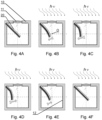
- Figs. 4A-4F show, in a cross section A-A' of Fig. 3 , subsequent steps of deformation of the converting element 20.
- the converting element 20 is mounted in a plane that is oblique to the optical axis of the lens 11. Therefore, incident light refracted by the lens 11 illuminates a larger area of the second layer 22 and delivers more energy to this layer than it would otherwise. Additionally, the motion of the converting element 20 leads to a more rapid exiting and subsequent entering of the second layer 22 made of the photo-mobile polymer to the focal area of the lens 11.
- the converting element 20 can bend with an increased amplitude and frequency, which causes more energy to be generated.
- the converting element 20 is mounted at an oblique angle with respect the focal axis of the lens 11.
- one end of the converting element 20 is rigidly and inseparably attached to the casing 10, while the other end of the converting element 20 is free.
- the converting element 20 is mounted on the casing 10 such that it can be deformed between the first position and the second position, while in the first position the incident light refracted by the lens 11 illuminates a larger area of the second layer 22 made of the photo-mobile polymer than it does in the second position.
- the lens 11 is a biconvex focusing lens having a focal length f selected so that the focal point O of the lens 11 lies on the second layer 22 when the converting element 20 is in the first position and, preferably, the focal point O lies outside the second layer 22 (or even outside the converting element 20) when the converting element 20 is in the second position.
- the converting element 20 in the first position, is essentially straight.
- the second layer 22 deforms, in particular by bending, which causes the bending of all the layers that constitute the converting element 20.
- the photo-piezoelectric generator of electrical energy from light energy allows cyclic bending of the converting element 20 under constant illumination with artificial or natural light. Additionally, the use of an antireflective/light-absorbing coating 12 on the inner walls of the casing 10 reduces the negative effect of light reflected from the inner walls of the casing 10, increasing the amplitude and/or frequency of bending of the converting element 20.
- mounting the converting element 20 at an oblique angle to the optical axis of the lens 11 increases the area of the illuminated surface. Additionally the converting element 20 exits/enters the focal point O of the lens 11 more rapidly. Therefore, the amplitude and/or frequency of bending is even higher, which in turn enhances the electrical energy yield. Additionally, depending on the dimensions of the lens 11, the width and length of the converting element 20 can be scaled in order to optimize the energy yield.
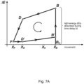
- Fig. 7A shows a work cycle of the generator according to present invention upon bending of the converting element 20 on the trajectory shown in Fig. 7B .
- Fig. 7B The motion of the converting element 20 is shown in Fig. 7B , wherein:
- the converting element 20 would halt at a boundary between the illuminated and unilluminated regions (point D in Fig. 7B ).
- the conversion of light energy into motion occurs with a delay ⁇ t.
- the inertness of the converting element 20 (that results from the accumulated kinetic Energy E k ) also allows for motion beyond point D.
- the mass of the converting element 20 is low, and its speed between points B ⁇ F and F ⁇ B is low, and therefore E k may be not sufficient to move the converting element 20 beyond point D and towards point F.
- Fig. 7A shows energetics of the work cycle of the generator upon bending of the converting element.
- the motion begins after time ⁇ t, during which the photo-mobile polymer 22 absorbs a threshold energy ⁇ E P , which initiates the motion of the converting element 20.
- the photo-mobile polymer 22 continues to absorb light and convert it into motion.
- the photo-mobile polymer 22 still contains a portion of accumulated energy ⁇ E>0, but does not absorb any more light.
- the converting element 20 continues its motion to point F, losing it energy ⁇ E .
- the movement to point D' begins due to the elasticity of the converting element 20.
- the polymer absorbs light energy, but the halting force does not appear, because the accumulated energy ⁇ E> ⁇ E P (in other words, the section D' ⁇ B' lasts less than ⁇ t ).
- the photo-mobile polymer 22 absorbs energy. After reaching accumulated energy ⁇ E P , another work cycle begins.
- the delay of motion on the section B ⁇ C can be achieved by placing the permanent magnet 31 and the ferromagnetic mass 30 in such a way that the converting element 20 halts its motion in point B until illumination appears.
- the appearance of illumination induces a driving force that induces the motion, but after a time period ⁇ t which is needed for the driving force of the photo-mobile polymer 22 to exceed the attractive force of the permanent magnet 31.
- the delay in point D (which causes the movement between points D ⁇ F ) can be achieved by the ferromagnetic mass 30 which is mounted on the free end of the converting element 20.
- a properly selected mass 30 ensures that the converting element 20 has enough kinetic energy that once the driving force vanishes, it can cross the distance between points D ⁇ F. Simultaneously, the mass 30 cannot diminish the elasticity of the converting element 20 which would prevent it from crossing the distance between points F ⁇ D.
- the ferromagnetic mass 30 enhances the return motion of the converting element 20. During the reverse motion form point F, the accumulated kinetic energy allows it to cross point D, in which the halting action of the driving force of the photo-mobile polymer 22 begins.
- the attractive force of the permanent magnet 31 and the mass of the ferromagnetic object 30 have to be selected such as to maintain cyclic work. Together with the elastic deformation force of the photo-mobile polymer 22, the halting action of the driving force has to be overcome, which would allow for the converting element to return to point B. If the aforementioned condition is fulfilled, then the energy diagram is the same as depicted in Fig. 7A , even though the photo-mobile polymer 22 does not show the delay between light absorption and motion.
- Figs. 9A-9F show, in a cross section A-A' of Fig.
Landscapes
- Mechanical Light Control Or Optical Switches (AREA)
Claims (12)
- Photo-piezoelektrischer Generator von elektrischer Energie aus Lichtenergie, wobei der Generator ein Gehäuse (10) und ein innerhalb des Gehäuses montiertes elastisches Umwandlungselement (20) umfasst, wobei das Umwandlungselement (20) so konfiguriert ist, dass es sich aufgrund dessen, dass es durch Licht beleuchtet wird, zyklisch zwischen einer ersten Position und einer zweiten Position verformt, während sich der Generator unter konstanter Beleuchtung durch Lichtenergie befindet.
- Generator nach Anspruch 1, wobei das elastische Umwandlungselement (20) eine erste Schicht (21) aus einem piezoelektrischen Material und eine daran angebrachte zweite Schicht (22) aus einem photomobilen Polymermaterial umfasst, wobei zwischen der ersten Schicht (21) und der zweiten Schicht (22) auf einer Seite der ersten Schicht (21) eine erste Elektrodenschicht (23A) vorgesehen ist und auf der anderen Seite der ersten Schicht (21) eine zweite Elektrodenschicht (23B) vorgesehen ist.
- Generator nach einem der vorhergehenden Ansprüche, wobei:- das elastische Umwandlungselement (20) auf einer Seite an der Innenwand des Gehäuses (10) montiert ist, wobei das Gehäuse (10) undurchsichtig ist;- an einer Seite des Gehäuses eine Linse (11) vorgesehen ist, wobei das Umwandlungselement (20) so montiert ist, dass von der Linse (11) gebrochenes einfallendes Licht einen größeren Bereich der zweiten Schicht (22) aus dem fotomobilen Polymer in der ersten Position als in der zweiten Position des Umwandlungselements (20) beleuchtet.
- Generator nach einem der vorhergehenden Ansprüche, wobei die Innenwände des Gehäuses (10) mit einem Antireflexmaterial (12) bedeckt sind.
- Generator nach einem der Ansprüche 2 bis 4, wobei das piezoelektrische Material der ersten Schicht (21) ein Material enthält, das piezoelektrische Eigenschaften aufweist, wie etwa Nanodrähte (21A) aus Zinkoxid (ZnO).
- Generator nach Anspruch 5, wobei die Nanodrähte (21A) aus Zinkoxid (ZnO) in einen elektrischen Isolator (21B) eingetaucht sind.
- Generator nach einem der Ansprüche 3 bis 6, wobei die Linse (11) eine bikonvexe Fokussierlinse mit einer Brennweite (/) ist, die so gewählt ist, dass der Brennpunkt der Linse (11) auf der zweiten Schicht (22) aus dem photomobilen Polymermaterial liegt, wenn sich das Umwandlungselement (20) in der ersten Position befindet.
- Generator nach einem der Ansprüche 3 bis 7, wobei das Umwandlungselement (20) in einer Ebene montiert ist, die senkrecht zur optischen Achse der Linse (11) verläuft.
- Generator nach einem der Ansprüche 3 bis 7, wobei das Umwandlungselement (20) in einer Ebene montiert ist, die schräg zur optischen Achse der Linse (11) verläuft.
- Generator nach einem der vorhergehenden Ansprüche, wobei das Umwandlungselement (20) an seinem einen Ende starr und untrennbar am Gehäuse (10) angebracht ist, während das andere Ende des Umwandlungselements (20) frei ist.
- Generator nach einem der Ansprüche 2 bis 10, wobei das photomobile Polymermaterial der zweiten Schicht (22) eine Verzögerung (Δt) zwischen dem Einschalten der Beleuchtung und dem Beginn der mechanischen Biegebewegung aufweist.
- Generator nach einem der Ansprüche 3 bis 10, ferner umfassend eine ferromagnetische Masse (30), die an dem freien Ende des Umwandlungselements (20) angebracht ist, und einen Permanentmagneten (31), der an dem Gehäuse (10) so montiert ist, dass sich die ferromagnetische Masse (30) mit dem Permanentmagneten (31) an einem Abschnitt der Trajektorie des Umwandlungselements (20) gegenseitig beeinflusst.
Priority Applications (2)
| Application Number | Priority Date | Filing Date | Title |
|---|---|---|---|
| PL21461595.7T PL4152589T3 (pl) | 2021-09-21 | 2021-09-21 | Foto-piezoelektryczny generator energii elektrycznej z energii świetlnej |
| EP21461595.7A EP4152589B1 (de) | 2021-09-21 | 2021-09-21 | Photo-piezoelektrischer generator von elektrischer energie aus lichtenergie |
Applications Claiming Priority (1)
| Application Number | Priority Date | Filing Date | Title |
|---|---|---|---|
| EP21461595.7A EP4152589B1 (de) | 2021-09-21 | 2021-09-21 | Photo-piezoelektrischer generator von elektrischer energie aus lichtenergie |
Publications (2)
| Publication Number | Publication Date |
|---|---|
| EP4152589A1 EP4152589A1 (de) | 2023-03-22 |
| EP4152589B1 true EP4152589B1 (de) | 2024-07-24 |
Family
ID=77913060
Family Applications (1)
| Application Number | Title | Priority Date | Filing Date |
|---|---|---|---|
| EP21461595.7A Active EP4152589B1 (de) | 2021-09-21 | 2021-09-21 | Photo-piezoelektrischer generator von elektrischer energie aus lichtenergie |
Country Status (2)
| Country | Link |
|---|---|
| EP (1) | EP4152589B1 (de) |
| PL (1) | PL4152589T3 (de) |
Family Cites Families (5)
| Publication number | Priority date | Publication date | Assignee | Title |
|---|---|---|---|---|
| IL304852B2 (en) * | 2016-08-26 | 2025-03-01 | Andrew Simon FILO | Modulating piezoelectric retroreflective multilayer film |
| CN109428515A (zh) * | 2017-08-29 | 2019-03-05 | 齐姗姗 | 一种微型复合振动发电机 |
| IT201800004538A1 (it) | 2018-04-16 | 2019-10-16 | Dispositivo di conversione energetica e metodo di produzione. | |
| KR101928966B1 (ko) * | 2018-05-28 | 2018-12-13 | 주식회사 썬에이치에스티 | 다중 에너지 하베스팅 입력을 이용한 멀티 스마트 센서 장치 |
| CN108809208B (zh) * | 2018-06-22 | 2020-05-15 | 中国电子科技集团公司第四十八研究所 | 一种路面能量收集装置 |
-
2021
- 2021-09-21 PL PL21461595.7T patent/PL4152589T3/pl unknown
- 2021-09-21 EP EP21461595.7A patent/EP4152589B1/de active Active
Also Published As
| Publication number | Publication date |
|---|---|
| PL4152589T3 (pl) | 2024-12-02 |
| EP4152589A1 (de) | 2023-03-22 |
Similar Documents
| Publication | Publication Date | Title |
|---|---|---|
| Kim et al. | Electromagnetic energy harvester based on a finger trigger rotational gear module and an array of disc Halbach magnets | |
| CN105958858B (zh) | 一种双层波浪形杂化纳米发电机 | |
| CN103840710B (zh) | 一种振动能量采集器 | |
| Chiba et al. | Elastomer transducers | |
| CN111130389A (zh) | 一种无源型介电弹性体风能采集装置及其应用 | |
| CN112240263A (zh) | 自发电浮标系统 | |
| KR102349781B1 (ko) | 압전 전자기 하이브리드 에너지 하베스터 | |
| KR20110049294A (ko) | 자가발전 매트 | |
| EP4152589A1 (de) | Photoelektrischer generator von elektrischer energie aus lichtenergie | |
| KR20140073063A (ko) | 압전 발전기 | |
| CN104578911B (zh) | 基于双稳态的无接触磁力式振动能量俘获器 | |
| CN111146852A (zh) | 一种伸缩式介电弹性体能量采集装置及其应用 | |
| US20150008795A1 (en) | Piezoelectric power generator | |
| CN203775075U (zh) | 微振动传感器 | |
| EP4220904A1 (de) | Elektromagnetische erntemaschine für kinetische energie | |
| CN205811876U (zh) | 一种双层波浪形杂化纳米发电机 | |
| KR101048881B1 (ko) | 파력 발전 장치 | |
| CN110138261B (zh) | 一种基于双电荷层的发电机及其发电方法 | |
| CN110190772B (zh) | 基于液体中双电荷层的独立感应式发电机及其发电方法 | |
| CN119051481A (zh) | 一种基于teng的自供能软体驱动器 | |
| KR101775710B1 (ko) | 다층구조로 적층된 압전소자를 이용한 발전장치 | |
| KR101598888B1 (ko) | 에너지 수집장치 | |
| CN112260582A (zh) | 一种磁悬浮压电式振动能量采集装置 | |
| CN118030351A (zh) | 波浪能采集器及采集方法、海洋监测系统 | |
| CN109450294B (zh) | 一种扇贝型风振发电装置 |
Legal Events
| Date | Code | Title | Description |
|---|---|---|---|
| PUAI | Public reference made under article 153(3) epc to a published international application that has entered the european phase |
Free format text: ORIGINAL CODE: 0009012 |
|
| STAA | Information on the status of an ep patent application or granted ep patent |
Free format text: STATUS: THE APPLICATION HAS BEEN PUBLISHED |
|
| AK | Designated contracting states |
Kind code of ref document: A1 Designated state(s): AL AT BE BG CH CY CZ DE DK EE ES FI FR GB GR HR HU IE IS IT LI LT LU LV MC MK MT NL NO PL PT RO RS SE SI SK SM TR |
|
| STAA | Information on the status of an ep patent application or granted ep patent |
Free format text: STATUS: REQUEST FOR EXAMINATION WAS MADE |
|
| 17P | Request for examination filed |
Effective date: 20230922 |
|
| RBV | Designated contracting states (corrected) |
Designated state(s): AL AT BE BG CH CY CZ DE DK EE ES FI FR GB GR HR HU IE IS IT LI LT LU LV MC MK MT NL NO PL PT RO RS SE SI SK SM TR |
|
| GRAP | Despatch of communication of intention to grant a patent |
Free format text: ORIGINAL CODE: EPIDOSNIGR1 |
|
| STAA | Information on the status of an ep patent application or granted ep patent |
Free format text: STATUS: GRANT OF PATENT IS INTENDED |
|
| INTG | Intention to grant announced |
Effective date: 20240322 |
|
| GRAS | Grant fee paid |
Free format text: ORIGINAL CODE: EPIDOSNIGR3 |
|
| GRAA | (expected) grant |
Free format text: ORIGINAL CODE: 0009210 |
|
| STAA | Information on the status of an ep patent application or granted ep patent |
Free format text: STATUS: THE PATENT HAS BEEN GRANTED |
|
| AK | Designated contracting states |
Kind code of ref document: B1 Designated state(s): AL AT BE BG CH CY CZ DE DK EE ES FI FR GB GR HR HU IE IS IT LI LT LU LV MC MK MT NL NO PL PT RO RS SE SI SK SM TR |
|
| REG | Reference to a national code |
Ref country code: GB Ref legal event code: FG4D |
|
| REG | Reference to a national code |
Ref country code: CH Ref legal event code: EP |
|
| REG | Reference to a national code |
Ref country code: IE Ref legal event code: FG4D Ref country code: DE Ref legal event code: R096 Ref document number: 602021016108 Country of ref document: DE |
|
| REG | Reference to a national code |
Ref country code: LT Ref legal event code: MG9D |
|
| REG | Reference to a national code |
Ref country code: NL Ref legal event code: MP Effective date: 20240724 |
|
| PG25 | Lapsed in a contracting state [announced via postgrant information from national office to epo] |
Ref country code: PT Free format text: LAPSE BECAUSE OF FAILURE TO SUBMIT A TRANSLATION OF THE DESCRIPTION OR TO PAY THE FEE WITHIN THE PRESCRIBED TIME-LIMIT Effective date: 20241125 |
|
| REG | Reference to a national code |
Ref country code: AT Ref legal event code: MK05 Ref document number: 1707234 Country of ref document: AT Kind code of ref document: T Effective date: 20240724 |
|
| PG25 | Lapsed in a contracting state [announced via postgrant information from national office to epo] |
Ref country code: NL Free format text: LAPSE BECAUSE OF FAILURE TO SUBMIT A TRANSLATION OF THE DESCRIPTION OR TO PAY THE FEE WITHIN THE PRESCRIBED TIME-LIMIT Effective date: 20240724 |
|
| PG25 | Lapsed in a contracting state [announced via postgrant information from national office to epo] |
Ref country code: PT Free format text: LAPSE BECAUSE OF FAILURE TO SUBMIT A TRANSLATION OF THE DESCRIPTION OR TO PAY THE FEE WITHIN THE PRESCRIBED TIME-LIMIT Effective date: 20241125 Ref country code: NL Free format text: LAPSE BECAUSE OF FAILURE TO SUBMIT A TRANSLATION OF THE DESCRIPTION OR TO PAY THE FEE WITHIN THE PRESCRIBED TIME-LIMIT Effective date: 20240724 |
|
| PG25 | Lapsed in a contracting state [announced via postgrant information from national office to epo] |
Ref country code: NO Free format text: LAPSE BECAUSE OF FAILURE TO SUBMIT A TRANSLATION OF THE DESCRIPTION OR TO PAY THE FEE WITHIN THE PRESCRIBED TIME-LIMIT Effective date: 20241024 |
|
| PG25 | Lapsed in a contracting state [announced via postgrant information from national office to epo] |
Ref country code: FI Free format text: LAPSE BECAUSE OF FAILURE TO SUBMIT A TRANSLATION OF THE DESCRIPTION OR TO PAY THE FEE WITHIN THE PRESCRIBED TIME-LIMIT Effective date: 20240724 Ref country code: GR Free format text: LAPSE BECAUSE OF FAILURE TO SUBMIT A TRANSLATION OF THE DESCRIPTION OR TO PAY THE FEE WITHIN THE PRESCRIBED TIME-LIMIT Effective date: 20241025 |
|
| PG25 | Lapsed in a contracting state [announced via postgrant information from national office to epo] |
Ref country code: BG Free format text: LAPSE BECAUSE OF FAILURE TO SUBMIT A TRANSLATION OF THE DESCRIPTION OR TO PAY THE FEE WITHIN THE PRESCRIBED TIME-LIMIT Effective date: 20240724 |
|
| PG25 | Lapsed in a contracting state [announced via postgrant information from national office to epo] |
Ref country code: LV Free format text: LAPSE BECAUSE OF FAILURE TO SUBMIT A TRANSLATION OF THE DESCRIPTION OR TO PAY THE FEE WITHIN THE PRESCRIBED TIME-LIMIT Effective date: 20240724 |
|
| PG25 | Lapsed in a contracting state [announced via postgrant information from national office to epo] |
Ref country code: IS Free format text: LAPSE BECAUSE OF FAILURE TO SUBMIT A TRANSLATION OF THE DESCRIPTION OR TO PAY THE FEE WITHIN THE PRESCRIBED TIME-LIMIT Effective date: 20241124 Ref country code: AT Free format text: LAPSE BECAUSE OF FAILURE TO SUBMIT A TRANSLATION OF THE DESCRIPTION OR TO PAY THE FEE WITHIN THE PRESCRIBED TIME-LIMIT Effective date: 20240724 |
|
| PG25 | Lapsed in a contracting state [announced via postgrant information from national office to epo] |
Ref country code: HR Free format text: LAPSE BECAUSE OF FAILURE TO SUBMIT A TRANSLATION OF THE DESCRIPTION OR TO PAY THE FEE WITHIN THE PRESCRIBED TIME-LIMIT Effective date: 20240724 |
|
| PG25 | Lapsed in a contracting state [announced via postgrant information from national office to epo] |
Ref country code: ES Free format text: LAPSE BECAUSE OF FAILURE TO SUBMIT A TRANSLATION OF THE DESCRIPTION OR TO PAY THE FEE WITHIN THE PRESCRIBED TIME-LIMIT Effective date: 20240724 Ref country code: RS Free format text: LAPSE BECAUSE OF FAILURE TO SUBMIT A TRANSLATION OF THE DESCRIPTION OR TO PAY THE FEE WITHIN THE PRESCRIBED TIME-LIMIT Effective date: 20241024 |
|
| PG25 | Lapsed in a contracting state [announced via postgrant information from national office to epo] |
Ref country code: RS Free format text: LAPSE BECAUSE OF FAILURE TO SUBMIT A TRANSLATION OF THE DESCRIPTION OR TO PAY THE FEE WITHIN THE PRESCRIBED TIME-LIMIT Effective date: 20241024 Ref country code: NO Free format text: LAPSE BECAUSE OF FAILURE TO SUBMIT A TRANSLATION OF THE DESCRIPTION OR TO PAY THE FEE WITHIN THE PRESCRIBED TIME-LIMIT Effective date: 20241024 Ref country code: LV Free format text: LAPSE BECAUSE OF FAILURE TO SUBMIT A TRANSLATION OF THE DESCRIPTION OR TO PAY THE FEE WITHIN THE PRESCRIBED TIME-LIMIT Effective date: 20240724 Ref country code: IS Free format text: LAPSE BECAUSE OF FAILURE TO SUBMIT A TRANSLATION OF THE DESCRIPTION OR TO PAY THE FEE WITHIN THE PRESCRIBED TIME-LIMIT Effective date: 20241124 Ref country code: HR Free format text: LAPSE BECAUSE OF FAILURE TO SUBMIT A TRANSLATION OF THE DESCRIPTION OR TO PAY THE FEE WITHIN THE PRESCRIBED TIME-LIMIT Effective date: 20240724 Ref country code: GR Free format text: LAPSE BECAUSE OF FAILURE TO SUBMIT A TRANSLATION OF THE DESCRIPTION OR TO PAY THE FEE WITHIN THE PRESCRIBED TIME-LIMIT Effective date: 20241025 Ref country code: FI Free format text: LAPSE BECAUSE OF FAILURE TO SUBMIT A TRANSLATION OF THE DESCRIPTION OR TO PAY THE FEE WITHIN THE PRESCRIBED TIME-LIMIT Effective date: 20240724 Ref country code: ES Free format text: LAPSE BECAUSE OF FAILURE TO SUBMIT A TRANSLATION OF THE DESCRIPTION OR TO PAY THE FEE WITHIN THE PRESCRIBED TIME-LIMIT Effective date: 20240724 Ref country code: BG Free format text: LAPSE BECAUSE OF FAILURE TO SUBMIT A TRANSLATION OF THE DESCRIPTION OR TO PAY THE FEE WITHIN THE PRESCRIBED TIME-LIMIT Effective date: 20240724 Ref country code: AT Free format text: LAPSE BECAUSE OF FAILURE TO SUBMIT A TRANSLATION OF THE DESCRIPTION OR TO PAY THE FEE WITHIN THE PRESCRIBED TIME-LIMIT Effective date: 20240724 |
|
| PG25 | Lapsed in a contracting state [announced via postgrant information from national office to epo] |
Ref country code: DK Free format text: LAPSE BECAUSE OF FAILURE TO SUBMIT A TRANSLATION OF THE DESCRIPTION OR TO PAY THE FEE WITHIN THE PRESCRIBED TIME-LIMIT Effective date: 20240724 Ref country code: RO Free format text: LAPSE BECAUSE OF FAILURE TO SUBMIT A TRANSLATION OF THE DESCRIPTION OR TO PAY THE FEE WITHIN THE PRESCRIBED TIME-LIMIT Effective date: 20240724 Ref country code: SM Free format text: LAPSE BECAUSE OF FAILURE TO SUBMIT A TRANSLATION OF THE DESCRIPTION OR TO PAY THE FEE WITHIN THE PRESCRIBED TIME-LIMIT Effective date: 20240724 |
|
| PG25 | Lapsed in a contracting state [announced via postgrant information from national office to epo] |
Ref country code: MC Free format text: LAPSE BECAUSE OF FAILURE TO SUBMIT A TRANSLATION OF THE DESCRIPTION OR TO PAY THE FEE WITHIN THE PRESCRIBED TIME-LIMIT Effective date: 20240724 Ref country code: EE Free format text: LAPSE BECAUSE OF FAILURE TO SUBMIT A TRANSLATION OF THE DESCRIPTION OR TO PAY THE FEE WITHIN THE PRESCRIBED TIME-LIMIT Effective date: 20240724 |
|
| PG25 | Lapsed in a contracting state [announced via postgrant information from national office to epo] |
Ref country code: CZ Free format text: LAPSE BECAUSE OF FAILURE TO SUBMIT A TRANSLATION OF THE DESCRIPTION OR TO PAY THE FEE WITHIN THE PRESCRIBED TIME-LIMIT Effective date: 20240724 |
|
| REG | Reference to a national code |
Ref country code: DE Ref legal event code: R097 Ref document number: 602021016108 Country of ref document: DE |
|
| PG25 | Lapsed in a contracting state [announced via postgrant information from national office to epo] |
Ref country code: SK Free format text: LAPSE BECAUSE OF FAILURE TO SUBMIT A TRANSLATION OF THE DESCRIPTION OR TO PAY THE FEE WITHIN THE PRESCRIBED TIME-LIMIT Effective date: 20240724 |
|
| REG | Reference to a national code |
Ref country code: CH Ref legal event code: PL |
|
| PG25 | Lapsed in a contracting state [announced via postgrant information from national office to epo] |
Ref country code: LU Free format text: LAPSE BECAUSE OF NON-PAYMENT OF DUE FEES Effective date: 20240921 |
|
| PLBE | No opposition filed within time limit |
Free format text: ORIGINAL CODE: 0009261 |
|
| STAA | Information on the status of an ep patent application or granted ep patent |
Free format text: STATUS: NO OPPOSITION FILED WITHIN TIME LIMIT |
|
| 26N | No opposition filed |
Effective date: 20250425 |
|
| REG | Reference to a national code |
Ref country code: BE Ref legal event code: MM Effective date: 20240930 |
|
| PG25 | Lapsed in a contracting state [announced via postgrant information from national office to epo] |
Ref country code: BE Free format text: LAPSE BECAUSE OF NON-PAYMENT OF DUE FEES Effective date: 20240930 |
|
| PG25 | Lapsed in a contracting state [announced via postgrant information from national office to epo] |
Ref country code: CH Free format text: LAPSE BECAUSE OF NON-PAYMENT OF DUE FEES Effective date: 20240930 |
|
| PG25 | Lapsed in a contracting state [announced via postgrant information from national office to epo] |
Ref country code: IE Free format text: LAPSE BECAUSE OF NON-PAYMENT OF DUE FEES Effective date: 20240921 |
|
| PG25 | Lapsed in a contracting state [announced via postgrant information from national office to epo] |
Ref country code: SE Free format text: LAPSE BECAUSE OF FAILURE TO SUBMIT A TRANSLATION OF THE DESCRIPTION OR TO PAY THE FEE WITHIN THE PRESCRIBED TIME-LIMIT Effective date: 20240724 |
|
| PGFP | Annual fee paid to national office [announced via postgrant information from national office to epo] |
Ref country code: DE Payment date: 20250929 Year of fee payment: 5 |
|
| PGFP | Annual fee paid to national office [announced via postgrant information from national office to epo] |
Ref country code: PL Payment date: 20250902 Year of fee payment: 5 Ref country code: IT Payment date: 20250919 Year of fee payment: 5 |
|
| PGFP | Annual fee paid to national office [announced via postgrant information from national office to epo] |
Ref country code: GB Payment date: 20250929 Year of fee payment: 5 |
|
| PGFP | Annual fee paid to national office [announced via postgrant information from national office to epo] |
Ref country code: FR Payment date: 20250925 Year of fee payment: 5 |
|
| PG25 | Lapsed in a contracting state [announced via postgrant information from national office to epo] |
Ref country code: CY Free format text: LAPSE BECAUSE OF FAILURE TO SUBMIT A TRANSLATION OF THE DESCRIPTION OR TO PAY THE FEE WITHIN THE PRESCRIBED TIME-LIMIT; INVALID AB INITIO Effective date: 20210921 |
|
| PG25 | Lapsed in a contracting state [announced via postgrant information from national office to epo] |
Ref country code: HU Free format text: LAPSE BECAUSE OF FAILURE TO SUBMIT A TRANSLATION OF THE DESCRIPTION OR TO PAY THE FEE WITHIN THE PRESCRIBED TIME-LIMIT; INVALID AB INITIO Effective date: 20210921 |