EP4152487A1 - Packaging film, electrochemical apparatus, and electronic apparatus - Google Patents
Packaging film, electrochemical apparatus, and electronic apparatus Download PDFInfo
- Publication number
- EP4152487A1 EP4152487A1 EP20935516.3A EP20935516A EP4152487A1 EP 4152487 A1 EP4152487 A1 EP 4152487A1 EP 20935516 A EP20935516 A EP 20935516A EP 4152487 A1 EP4152487 A1 EP 4152487A1
- Authority
- EP
- European Patent Office
- Prior art keywords
- layer
- packaging film
- carbon
- electrode plate
- polymer resin
- Prior art date
- Legal status (The legal status is an assumption and is not a legal conclusion. Google has not performed a legal analysis and makes no representation as to the accuracy of the status listed.)
- Pending
Links
- 229920006280 packaging film Polymers 0.000 title claims abstract description 98
- 239000012785 packaging film Substances 0.000 title claims abstract description 98
- 239000010410 layer Substances 0.000 claims abstract description 163
- 239000011241 protective layer Substances 0.000 claims abstract description 50
- 239000002952 polymeric resin Substances 0.000 claims abstract description 46
- 229920003002 synthetic resin Polymers 0.000 claims abstract description 46
- 239000003575 carbonaceous material Substances 0.000 claims abstract description 35
- 238000007789 sealing Methods 0.000 claims abstract description 21
- 229910052751 metal Inorganic materials 0.000 claims abstract description 19
- 239000002184 metal Substances 0.000 claims abstract description 19
- OKTJSMMVPCPJKN-UHFFFAOYSA-N Carbon Chemical compound [C] OKTJSMMVPCPJKN-UHFFFAOYSA-N 0.000 claims description 80
- 239000002041 carbon nanotube Substances 0.000 claims description 46
- 229910021393 carbon nanotube Inorganic materials 0.000 claims description 46
- 229910052799 carbon Inorganic materials 0.000 claims description 33
- 229920000049 Carbon (fiber) Polymers 0.000 claims description 23
- 239000004917 carbon fiber Substances 0.000 claims description 23
- 239000002210 silicon-based material Substances 0.000 claims description 14
- LIVNPJMFVYWSIS-UHFFFAOYSA-N silicon monoxide Chemical compound [Si-]#[O+] LIVNPJMFVYWSIS-UHFFFAOYSA-N 0.000 claims description 12
- -1 polyethylene terephthalate Polymers 0.000 claims description 9
- 239000004743 Polypropylene Substances 0.000 claims description 5
- 229920001155 polypropylene Polymers 0.000 claims description 5
- XUIMIQQOPSSXEZ-UHFFFAOYSA-N Silicon Chemical compound [Si] XUIMIQQOPSSXEZ-UHFFFAOYSA-N 0.000 claims description 4
- 229910052710 silicon Inorganic materials 0.000 claims description 4
- 239000010703 silicon Substances 0.000 claims description 4
- 238000004804 winding Methods 0.000 claims description 4
- 239000004677 Nylon Substances 0.000 claims description 3
- 239000002131 composite material Substances 0.000 claims description 3
- 238000003475 lamination Methods 0.000 claims description 3
- 239000000463 material Substances 0.000 claims description 3
- 239000002048 multi walled nanotube Substances 0.000 claims description 3
- 229920001778 nylon Polymers 0.000 claims description 3
- 229920000139 polyethylene terephthalate Polymers 0.000 claims description 3
- 239000005020 polyethylene terephthalate Substances 0.000 claims description 3
- 239000002153 silicon-carbon composite material Substances 0.000 claims description 3
- 239000002109 single walled nanotube Substances 0.000 claims description 3
- 230000008961 swelling Effects 0.000 description 24
- 238000002360 preparation method Methods 0.000 description 21
- HBBGRARXTFLTSG-UHFFFAOYSA-N Lithium ion Chemical compound [Li+] HBBGRARXTFLTSG-UHFFFAOYSA-N 0.000 description 18
- 229910001416 lithium ion Inorganic materials 0.000 description 18
- 230000001965 increasing effect Effects 0.000 description 12
- 230000000052 comparative effect Effects 0.000 description 10
- 238000000034 method Methods 0.000 description 9
- 238000012360 testing method Methods 0.000 description 9
- 238000009941 weaving Methods 0.000 description 7
- 229910052782 aluminium Inorganic materials 0.000 description 5
- XAGFODPZIPBFFR-UHFFFAOYSA-N aluminium Chemical compound [Al] XAGFODPZIPBFFR-UHFFFAOYSA-N 0.000 description 5
- 230000000694 effects Effects 0.000 description 5
- 239000011888 foil Substances 0.000 description 5
- 230000035515 penetration Effects 0.000 description 5
- 239000011856 silicon-based particle Substances 0.000 description 5
- 238000009864 tensile test Methods 0.000 description 5
- 230000002708 enhancing effect Effects 0.000 description 4
- 229910052744 lithium Inorganic materials 0.000 description 4
- 238000010008 shearing Methods 0.000 description 4
- 239000002002 slurry Substances 0.000 description 4
- WHXSMMKQMYFTQS-UHFFFAOYSA-N Lithium Chemical compound [Li] WHXSMMKQMYFTQS-UHFFFAOYSA-N 0.000 description 3
- 238000005520 cutting process Methods 0.000 description 3
- 230000001351 cycling effect Effects 0.000 description 3
- 230000003247 decreasing effect Effects 0.000 description 3
- 239000003792 electrolyte Substances 0.000 description 3
- 230000002401 inhibitory effect Effects 0.000 description 3
- SECXISVLQFMRJM-UHFFFAOYSA-N N-Methylpyrrolidone Chemical compound CN1CCCC1=O SECXISVLQFMRJM-UHFFFAOYSA-N 0.000 description 2
- 230000004913 activation Effects 0.000 description 2
- 239000011149 active material Substances 0.000 description 2
- 239000003990 capacitor Substances 0.000 description 2
- 238000005266 casting Methods 0.000 description 2
- 238000010586 diagram Methods 0.000 description 2
- VNWKTOKETHGBQD-UHFFFAOYSA-N methane Chemical compound C VNWKTOKETHGBQD-UHFFFAOYSA-N 0.000 description 2
- 239000000203 mixture Substances 0.000 description 2
- 230000003647 oxidation Effects 0.000 description 2
- 238000007254 oxidation reaction Methods 0.000 description 2
- 229920000642 polymer Polymers 0.000 description 2
- 229920002981 polyvinylidene fluoride Polymers 0.000 description 2
- 238000003825 pressing Methods 0.000 description 2
- 238000012545 processing Methods 0.000 description 2
- 238000010998 test method Methods 0.000 description 2
- XLYOFNOQVPJJNP-UHFFFAOYSA-N water Substances O XLYOFNOQVPJJNP-UHFFFAOYSA-N 0.000 description 2
- 229920000178 Acrylic resin Polymers 0.000 description 1
- 239000004925 Acrylic resin Substances 0.000 description 1
- RYGMFSIKBFXOCR-UHFFFAOYSA-N Copper Chemical compound [Cu] RYGMFSIKBFXOCR-UHFFFAOYSA-N 0.000 description 1
- 229910032387 LiCoO2 Inorganic materials 0.000 description 1
- 239000004698 Polyethylene Substances 0.000 description 1
- QVGXLLKOCUKJST-UHFFFAOYSA-N atomic oxygen Chemical compound [O] QVGXLLKOCUKJST-UHFFFAOYSA-N 0.000 description 1
- 230000009286 beneficial effect Effects 0.000 description 1
- 239000011889 copper foil Substances 0.000 description 1
- 230000007797 corrosion Effects 0.000 description 1
- 238000005260 corrosion Methods 0.000 description 1
- 230000000593 degrading effect Effects 0.000 description 1
- 239000008367 deionised water Substances 0.000 description 1
- 229910021641 deionized water Inorganic materials 0.000 description 1
- 238000003487 electrochemical reaction Methods 0.000 description 1
- 238000004146 energy storage Methods 0.000 description 1
- 239000003822 epoxy resin Substances 0.000 description 1
- 239000000446 fuel Substances 0.000 description 1
- 239000010439 graphite Substances 0.000 description 1
- 229910002804 graphite Inorganic materials 0.000 description 1
- 230000017525 heat dissipation Effects 0.000 description 1
- 230000000670 limiting effect Effects 0.000 description 1
- 238000006138 lithiation reaction Methods 0.000 description 1
- 238000010295 mobile communication Methods 0.000 description 1
- 238000012986 modification Methods 0.000 description 1
- 230000004048 modification Effects 0.000 description 1
- 239000007773 negative electrode material Substances 0.000 description 1
- 239000003960 organic solvent Substances 0.000 description 1
- 239000001301 oxygen Substances 0.000 description 1
- 229910052760 oxygen Inorganic materials 0.000 description 1
- 230000036961 partial effect Effects 0.000 description 1
- 229920000647 polyepoxide Polymers 0.000 description 1
- 229920000573 polyethylene Polymers 0.000 description 1
- 229920002635 polyurethane Polymers 0.000 description 1
- 239000004814 polyurethane Substances 0.000 description 1
- 239000007774 positive electrode material Substances 0.000 description 1
- 238000010298 pulverizing process Methods 0.000 description 1
- 238000004080 punching Methods 0.000 description 1
- 229920005989 resin Polymers 0.000 description 1
- 239000011347 resin Substances 0.000 description 1
- 239000002904 solvent Substances 0.000 description 1
- 229920003048 styrene butadiene rubber Polymers 0.000 description 1
Images

Classifications
-
- B—PERFORMING OPERATIONS; TRANSPORTING
- B32—LAYERED PRODUCTS
- B32B—LAYERED PRODUCTS, i.e. PRODUCTS BUILT-UP OF STRATA OF FLAT OR NON-FLAT, e.g. CELLULAR OR HONEYCOMB, FORM
- B32B5/00—Layered products characterised by the non- homogeneity or physical structure, i.e. comprising a fibrous, filamentary, particulate or foam layer; Layered products characterised by having a layer differing constitutionally or physically in different parts
- B32B5/02—Layered products characterised by the non- homogeneity or physical structure, i.e. comprising a fibrous, filamentary, particulate or foam layer; Layered products characterised by having a layer differing constitutionally or physically in different parts characterised by structural features of a fibrous or filamentary layer
- B32B5/024—Woven fabric
-
- H—ELECTRICITY
- H01—ELECTRIC ELEMENTS
- H01M—PROCESSES OR MEANS, e.g. BATTERIES, FOR THE DIRECT CONVERSION OF CHEMICAL ENERGY INTO ELECTRICAL ENERGY
- H01M50/00—Constructional details or processes of manufacture of the non-active parts of electrochemical cells other than fuel cells, e.g. hybrid cells
- H01M50/10—Primary casings; Jackets or wrappings
- H01M50/116—Primary casings; Jackets or wrappings characterised by the material
- H01M50/124—Primary casings; Jackets or wrappings characterised by the material having a layered structure
- H01M50/126—Primary casings; Jackets or wrappings characterised by the material having a layered structure comprising three or more layers
-
- B—PERFORMING OPERATIONS; TRANSPORTING
- B32—LAYERED PRODUCTS
- B32B—LAYERED PRODUCTS, i.e. PRODUCTS BUILT-UP OF STRATA OF FLAT OR NON-FLAT, e.g. CELLULAR OR HONEYCOMB, FORM
- B32B15/00—Layered products comprising a layer of metal
- B32B15/04—Layered products comprising a layer of metal comprising metal as the main or only constituent of a layer, which is next to another layer of the same or of a different material
- B32B15/08—Layered products comprising a layer of metal comprising metal as the main or only constituent of a layer, which is next to another layer of the same or of a different material of synthetic resin
- B32B15/082—Layered products comprising a layer of metal comprising metal as the main or only constituent of a layer, which is next to another layer of the same or of a different material of synthetic resin comprising vinyl resins; comprising acrylic resins
-
- B—PERFORMING OPERATIONS; TRANSPORTING
- B32—LAYERED PRODUCTS
- B32B—LAYERED PRODUCTS, i.e. PRODUCTS BUILT-UP OF STRATA OF FLAT OR NON-FLAT, e.g. CELLULAR OR HONEYCOMB, FORM
- B32B15/00—Layered products comprising a layer of metal
- B32B15/04—Layered products comprising a layer of metal comprising metal as the main or only constituent of a layer, which is next to another layer of the same or of a different material
- B32B15/08—Layered products comprising a layer of metal comprising metal as the main or only constituent of a layer, which is next to another layer of the same or of a different material of synthetic resin
- B32B15/085—Layered products comprising a layer of metal comprising metal as the main or only constituent of a layer, which is next to another layer of the same or of a different material of synthetic resin comprising polyolefins
-
- B—PERFORMING OPERATIONS; TRANSPORTING
- B32—LAYERED PRODUCTS
- B32B—LAYERED PRODUCTS, i.e. PRODUCTS BUILT-UP OF STRATA OF FLAT OR NON-FLAT, e.g. CELLULAR OR HONEYCOMB, FORM
- B32B15/00—Layered products comprising a layer of metal
- B32B15/04—Layered products comprising a layer of metal comprising metal as the main or only constituent of a layer, which is next to another layer of the same or of a different material
- B32B15/08—Layered products comprising a layer of metal comprising metal as the main or only constituent of a layer, which is next to another layer of the same or of a different material of synthetic resin
- B32B15/092—Layered products comprising a layer of metal comprising metal as the main or only constituent of a layer, which is next to another layer of the same or of a different material of synthetic resin comprising epoxy resins
-
- B—PERFORMING OPERATIONS; TRANSPORTING
- B32—LAYERED PRODUCTS
- B32B—LAYERED PRODUCTS, i.e. PRODUCTS BUILT-UP OF STRATA OF FLAT OR NON-FLAT, e.g. CELLULAR OR HONEYCOMB, FORM
- B32B15/00—Layered products comprising a layer of metal
- B32B15/04—Layered products comprising a layer of metal comprising metal as the main or only constituent of a layer, which is next to another layer of the same or of a different material
- B32B15/08—Layered products comprising a layer of metal comprising metal as the main or only constituent of a layer, which is next to another layer of the same or of a different material of synthetic resin
- B32B15/095—Layered products comprising a layer of metal comprising metal as the main or only constituent of a layer, which is next to another layer of the same or of a different material of synthetic resin comprising polyurethanes
-
- B—PERFORMING OPERATIONS; TRANSPORTING
- B32—LAYERED PRODUCTS
- B32B—LAYERED PRODUCTS, i.e. PRODUCTS BUILT-UP OF STRATA OF FLAT OR NON-FLAT, e.g. CELLULAR OR HONEYCOMB, FORM
- B32B15/00—Layered products comprising a layer of metal
- B32B15/14—Layered products comprising a layer of metal next to a fibrous or filamentary layer
-
- B—PERFORMING OPERATIONS; TRANSPORTING
- B32—LAYERED PRODUCTS
- B32B—LAYERED PRODUCTS, i.e. PRODUCTS BUILT-UP OF STRATA OF FLAT OR NON-FLAT, e.g. CELLULAR OR HONEYCOMB, FORM
- B32B15/00—Layered products comprising a layer of metal
- B32B15/20—Layered products comprising a layer of metal comprising aluminium or copper
-
- B—PERFORMING OPERATIONS; TRANSPORTING
- B32—LAYERED PRODUCTS
- B32B—LAYERED PRODUCTS, i.e. PRODUCTS BUILT-UP OF STRATA OF FLAT OR NON-FLAT, e.g. CELLULAR OR HONEYCOMB, FORM
- B32B27/00—Layered products comprising a layer of synthetic resin
- B32B27/12—Layered products comprising a layer of synthetic resin next to a fibrous or filamentary layer
-
- B—PERFORMING OPERATIONS; TRANSPORTING
- B32—LAYERED PRODUCTS
- B32B—LAYERED PRODUCTS, i.e. PRODUCTS BUILT-UP OF STRATA OF FLAT OR NON-FLAT, e.g. CELLULAR OR HONEYCOMB, FORM
- B32B27/00—Layered products comprising a layer of synthetic resin
- B32B27/18—Layered products comprising a layer of synthetic resin characterised by the use of special additives
-
- B—PERFORMING OPERATIONS; TRANSPORTING
- B32—LAYERED PRODUCTS
- B32B—LAYERED PRODUCTS, i.e. PRODUCTS BUILT-UP OF STRATA OF FLAT OR NON-FLAT, e.g. CELLULAR OR HONEYCOMB, FORM
- B32B27/00—Layered products comprising a layer of synthetic resin
- B32B27/30—Layered products comprising a layer of synthetic resin comprising vinyl (co)polymers; comprising acrylic (co)polymers
- B32B27/308—Layered products comprising a layer of synthetic resin comprising vinyl (co)polymers; comprising acrylic (co)polymers comprising acrylic (co)polymers
-
- B—PERFORMING OPERATIONS; TRANSPORTING
- B32—LAYERED PRODUCTS
- B32B—LAYERED PRODUCTS, i.e. PRODUCTS BUILT-UP OF STRATA OF FLAT OR NON-FLAT, e.g. CELLULAR OR HONEYCOMB, FORM
- B32B27/00—Layered products comprising a layer of synthetic resin
- B32B27/32—Layered products comprising a layer of synthetic resin comprising polyolefins
-
- B—PERFORMING OPERATIONS; TRANSPORTING
- B32—LAYERED PRODUCTS
- B32B—LAYERED PRODUCTS, i.e. PRODUCTS BUILT-UP OF STRATA OF FLAT OR NON-FLAT, e.g. CELLULAR OR HONEYCOMB, FORM
- B32B27/00—Layered products comprising a layer of synthetic resin
- B32B27/34—Layered products comprising a layer of synthetic resin comprising polyamides
-
- B—PERFORMING OPERATIONS; TRANSPORTING
- B32—LAYERED PRODUCTS
- B32B—LAYERED PRODUCTS, i.e. PRODUCTS BUILT-UP OF STRATA OF FLAT OR NON-FLAT, e.g. CELLULAR OR HONEYCOMB, FORM
- B32B27/00—Layered products comprising a layer of synthetic resin
- B32B27/36—Layered products comprising a layer of synthetic resin comprising polyesters
-
- B—PERFORMING OPERATIONS; TRANSPORTING
- B32—LAYERED PRODUCTS
- B32B—LAYERED PRODUCTS, i.e. PRODUCTS BUILT-UP OF STRATA OF FLAT OR NON-FLAT, e.g. CELLULAR OR HONEYCOMB, FORM
- B32B27/00—Layered products comprising a layer of synthetic resin
- B32B27/38—Layered products comprising a layer of synthetic resin comprising epoxy resins
-
- B—PERFORMING OPERATIONS; TRANSPORTING
- B32—LAYERED PRODUCTS
- B32B—LAYERED PRODUCTS, i.e. PRODUCTS BUILT-UP OF STRATA OF FLAT OR NON-FLAT, e.g. CELLULAR OR HONEYCOMB, FORM
- B32B27/00—Layered products comprising a layer of synthetic resin
- B32B27/40—Layered products comprising a layer of synthetic resin comprising polyurethanes
-
- B—PERFORMING OPERATIONS; TRANSPORTING
- B32—LAYERED PRODUCTS
- B32B—LAYERED PRODUCTS, i.e. PRODUCTS BUILT-UP OF STRATA OF FLAT OR NON-FLAT, e.g. CELLULAR OR HONEYCOMB, FORM
- B32B7/00—Layered products characterised by the relation between layers; Layered products characterised by the relative orientation of features between layers, or by the relative values of a measurable parameter between layers, i.e. products comprising layers having different physical, chemical or physicochemical properties; Layered products characterised by the interconnection of layers
- B32B7/02—Physical, chemical or physicochemical properties
-
- B—PERFORMING OPERATIONS; TRANSPORTING
- B32—LAYERED PRODUCTS
- B32B—LAYERED PRODUCTS, i.e. PRODUCTS BUILT-UP OF STRATA OF FLAT OR NON-FLAT, e.g. CELLULAR OR HONEYCOMB, FORM
- B32B7/00—Layered products characterised by the relation between layers; Layered products characterised by the relative orientation of features between layers, or by the relative values of a measurable parameter between layers, i.e. products comprising layers having different physical, chemical or physicochemical properties; Layered products characterised by the interconnection of layers
- B32B7/04—Interconnection of layers
- B32B7/12—Interconnection of layers using interposed adhesives or interposed materials with bonding properties
-
- H—ELECTRICITY
- H01—ELECTRIC ELEMENTS
- H01M—PROCESSES OR MEANS, e.g. BATTERIES, FOR THE DIRECT CONVERSION OF CHEMICAL ENERGY INTO ELECTRICAL ENERGY
- H01M4/00—Electrodes
- H01M4/02—Electrodes composed of, or comprising, active material
- H01M4/36—Selection of substances as active materials, active masses, active liquids
- H01M4/362—Composites
- H01M4/364—Composites as mixtures
-
- H—ELECTRICITY
- H01—ELECTRIC ELEMENTS
- H01M—PROCESSES OR MEANS, e.g. BATTERIES, FOR THE DIRECT CONVERSION OF CHEMICAL ENERGY INTO ELECTRICAL ENERGY
- H01M4/00—Electrodes
- H01M4/02—Electrodes composed of, or comprising, active material
- H01M4/36—Selection of substances as active materials, active masses, active liquids
- H01M4/38—Selection of substances as active materials, active masses, active liquids of elements or alloys
- H01M4/386—Silicon or alloys based on silicon
-
- H—ELECTRICITY
- H01—ELECTRIC ELEMENTS
- H01M—PROCESSES OR MEANS, e.g. BATTERIES, FOR THE DIRECT CONVERSION OF CHEMICAL ENERGY INTO ELECTRICAL ENERGY
- H01M4/00—Electrodes
- H01M4/02—Electrodes composed of, or comprising, active material
- H01M4/36—Selection of substances as active materials, active masses, active liquids
- H01M4/48—Selection of substances as active materials, active masses, active liquids of inorganic oxides or hydroxides
- H01M4/483—Selection of substances as active materials, active masses, active liquids of inorganic oxides or hydroxides for non-aqueous cells
-
- H—ELECTRICITY
- H01—ELECTRIC ELEMENTS
- H01M—PROCESSES OR MEANS, e.g. BATTERIES, FOR THE DIRECT CONVERSION OF CHEMICAL ENERGY INTO ELECTRICAL ENERGY
- H01M4/00—Electrodes
- H01M4/02—Electrodes composed of, or comprising, active material
- H01M4/36—Selection of substances as active materials, active masses, active liquids
- H01M4/58—Selection of substances as active materials, active masses, active liquids of inorganic compounds other than oxides or hydroxides, e.g. sulfides, selenides, tellurides, halogenides or LiCoFy; of polyanionic structures, e.g. phosphates, silicates or borates
- H01M4/583—Carbonaceous material, e.g. graphite-intercalation compounds or CFx
- H01M4/587—Carbonaceous material, e.g. graphite-intercalation compounds or CFx for inserting or intercalating light metals
-
- H—ELECTRICITY
- H01—ELECTRIC ELEMENTS
- H01M—PROCESSES OR MEANS, e.g. BATTERIES, FOR THE DIRECT CONVERSION OF CHEMICAL ENERGY INTO ELECTRICAL ENERGY
- H01M50/00—Constructional details or processes of manufacture of the non-active parts of electrochemical cells other than fuel cells, e.g. hybrid cells
- H01M50/10—Primary casings; Jackets or wrappings
- H01M50/102—Primary casings; Jackets or wrappings characterised by their shape or physical structure
- H01M50/105—Pouches or flexible bags
-
- H—ELECTRICITY
- H01—ELECTRIC ELEMENTS
- H01M—PROCESSES OR MEANS, e.g. BATTERIES, FOR THE DIRECT CONVERSION OF CHEMICAL ENERGY INTO ELECTRICAL ENERGY
- H01M50/00—Constructional details or processes of manufacture of the non-active parts of electrochemical cells other than fuel cells, e.g. hybrid cells
- H01M50/10—Primary casings; Jackets or wrappings
- H01M50/116—Primary casings; Jackets or wrappings characterised by the material
- H01M50/117—Inorganic material
- H01M50/119—Metals
-
- H—ELECTRICITY
- H01—ELECTRIC ELEMENTS
- H01M—PROCESSES OR MEANS, e.g. BATTERIES, FOR THE DIRECT CONVERSION OF CHEMICAL ENERGY INTO ELECTRICAL ENERGY
- H01M50/00—Constructional details or processes of manufacture of the non-active parts of electrochemical cells other than fuel cells, e.g. hybrid cells
- H01M50/10—Primary casings; Jackets or wrappings
- H01M50/116—Primary casings; Jackets or wrappings characterised by the material
- H01M50/121—Organic material
-
- H—ELECTRICITY
- H01—ELECTRIC ELEMENTS
- H01M—PROCESSES OR MEANS, e.g. BATTERIES, FOR THE DIRECT CONVERSION OF CHEMICAL ENERGY INTO ELECTRICAL ENERGY
- H01M50/00—Constructional details or processes of manufacture of the non-active parts of electrochemical cells other than fuel cells, e.g. hybrid cells
- H01M50/10—Primary casings; Jackets or wrappings
- H01M50/116—Primary casings; Jackets or wrappings characterised by the material
- H01M50/122—Composite material consisting of a mixture of organic and inorganic materials
-
- H—ELECTRICITY
- H01—ELECTRIC ELEMENTS
- H01M—PROCESSES OR MEANS, e.g. BATTERIES, FOR THE DIRECT CONVERSION OF CHEMICAL ENERGY INTO ELECTRICAL ENERGY
- H01M50/00—Constructional details or processes of manufacture of the non-active parts of electrochemical cells other than fuel cells, e.g. hybrid cells
- H01M50/10—Primary casings; Jackets or wrappings
- H01M50/116—Primary casings; Jackets or wrappings characterised by the material
- H01M50/124—Primary casings; Jackets or wrappings characterised by the material having a layered structure
- H01M50/126—Primary casings; Jackets or wrappings characterised by the material having a layered structure comprising three or more layers
- H01M50/128—Primary casings; Jackets or wrappings characterised by the material having a layered structure comprising three or more layers with two or more layers of only inorganic material
-
- H—ELECTRICITY
- H01—ELECTRIC ELEMENTS
- H01M—PROCESSES OR MEANS, e.g. BATTERIES, FOR THE DIRECT CONVERSION OF CHEMICAL ENERGY INTO ELECTRICAL ENERGY
- H01M50/00—Constructional details or processes of manufacture of the non-active parts of electrochemical cells other than fuel cells, e.g. hybrid cells
- H01M50/10—Primary casings; Jackets or wrappings
- H01M50/116—Primary casings; Jackets or wrappings characterised by the material
- H01M50/124—Primary casings; Jackets or wrappings characterised by the material having a layered structure
- H01M50/126—Primary casings; Jackets or wrappings characterised by the material having a layered structure comprising three or more layers
- H01M50/129—Primary casings; Jackets or wrappings characterised by the material having a layered structure comprising three or more layers with two or more layers of only organic material
-
- H—ELECTRICITY
- H01—ELECTRIC ELEMENTS
- H01M—PROCESSES OR MEANS, e.g. BATTERIES, FOR THE DIRECT CONVERSION OF CHEMICAL ENERGY INTO ELECTRICAL ENERGY
- H01M50/00—Constructional details or processes of manufacture of the non-active parts of electrochemical cells other than fuel cells, e.g. hybrid cells
- H01M50/10—Primary casings; Jackets or wrappings
- H01M50/131—Primary casings; Jackets or wrappings characterised by physical properties, e.g. gas permeability, size or heat resistance
- H01M50/133—Thickness
-
- B—PERFORMING OPERATIONS; TRANSPORTING
- B32—LAYERED PRODUCTS
- B32B—LAYERED PRODUCTS, i.e. PRODUCTS BUILT-UP OF STRATA OF FLAT OR NON-FLAT, e.g. CELLULAR OR HONEYCOMB, FORM
- B32B2255/00—Coating on the layer surface
- B32B2255/06—Coating on the layer surface on metal layer
-
- B—PERFORMING OPERATIONS; TRANSPORTING
- B32—LAYERED PRODUCTS
- B32B—LAYERED PRODUCTS, i.e. PRODUCTS BUILT-UP OF STRATA OF FLAT OR NON-FLAT, e.g. CELLULAR OR HONEYCOMB, FORM
- B32B2255/00—Coating on the layer surface
- B32B2255/20—Inorganic coating
-
- B—PERFORMING OPERATIONS; TRANSPORTING
- B32—LAYERED PRODUCTS
- B32B—LAYERED PRODUCTS, i.e. PRODUCTS BUILT-UP OF STRATA OF FLAT OR NON-FLAT, e.g. CELLULAR OR HONEYCOMB, FORM
- B32B2260/00—Layered product comprising an impregnated, embedded, or bonded layer wherein the layer comprises an impregnation, embedding, or binder material
- B32B2260/02—Composition of the impregnated, bonded or embedded layer
- B32B2260/021—Fibrous or filamentary layer
-
- B—PERFORMING OPERATIONS; TRANSPORTING
- B32—LAYERED PRODUCTS
- B32B—LAYERED PRODUCTS, i.e. PRODUCTS BUILT-UP OF STRATA OF FLAT OR NON-FLAT, e.g. CELLULAR OR HONEYCOMB, FORM
- B32B2260/00—Layered product comprising an impregnated, embedded, or bonded layer wherein the layer comprises an impregnation, embedding, or binder material
- B32B2260/04—Impregnation, embedding, or binder material
- B32B2260/046—Synthetic resin
-
- B—PERFORMING OPERATIONS; TRANSPORTING
- B32—LAYERED PRODUCTS
- B32B—LAYERED PRODUCTS, i.e. PRODUCTS BUILT-UP OF STRATA OF FLAT OR NON-FLAT, e.g. CELLULAR OR HONEYCOMB, FORM
- B32B2262/00—Composition or structural features of fibres which form a fibrous or filamentary layer or are present as additives
- B32B2262/10—Inorganic fibres
- B32B2262/106—Carbon fibres, e.g. graphite fibres
-
- B—PERFORMING OPERATIONS; TRANSPORTING
- B32—LAYERED PRODUCTS
- B32B—LAYERED PRODUCTS, i.e. PRODUCTS BUILT-UP OF STRATA OF FLAT OR NON-FLAT, e.g. CELLULAR OR HONEYCOMB, FORM
- B32B2307/00—Properties of the layers or laminate
- B32B2307/30—Properties of the layers or laminate having particular thermal properties
- B32B2307/31—Heat sealable
-
- B—PERFORMING OPERATIONS; TRANSPORTING
- B32—LAYERED PRODUCTS
- B32B—LAYERED PRODUCTS, i.e. PRODUCTS BUILT-UP OF STRATA OF FLAT OR NON-FLAT, e.g. CELLULAR OR HONEYCOMB, FORM
- B32B2307/00—Properties of the layers or laminate
- B32B2307/40—Properties of the layers or laminate having particular optical properties
- B32B2307/408—Matt, dull surface
-
- B—PERFORMING OPERATIONS; TRANSPORTING
- B32—LAYERED PRODUCTS
- B32B—LAYERED PRODUCTS, i.e. PRODUCTS BUILT-UP OF STRATA OF FLAT OR NON-FLAT, e.g. CELLULAR OR HONEYCOMB, FORM
- B32B2307/00—Properties of the layers or laminate
- B32B2307/70—Other properties
- B32B2307/732—Dimensional properties
-
- B—PERFORMING OPERATIONS; TRANSPORTING
- B32—LAYERED PRODUCTS
- B32B—LAYERED PRODUCTS, i.e. PRODUCTS BUILT-UP OF STRATA OF FLAT OR NON-FLAT, e.g. CELLULAR OR HONEYCOMB, FORM
- B32B2439/00—Containers; Receptacles
- B32B2439/40—Closed containers
-
- B—PERFORMING OPERATIONS; TRANSPORTING
- B32—LAYERED PRODUCTS
- B32B—LAYERED PRODUCTS, i.e. PRODUCTS BUILT-UP OF STRATA OF FLAT OR NON-FLAT, e.g. CELLULAR OR HONEYCOMB, FORM
- B32B2457/00—Electrical equipment
- B32B2457/10—Batteries
-
- B—PERFORMING OPERATIONS; TRANSPORTING
- B32—LAYERED PRODUCTS
- B32B—LAYERED PRODUCTS, i.e. PRODUCTS BUILT-UP OF STRATA OF FLAT OR NON-FLAT, e.g. CELLULAR OR HONEYCOMB, FORM
- B32B2553/00—Packaging equipment or accessories not otherwise provided for
-
- H—ELECTRICITY
- H01—ELECTRIC ELEMENTS
- H01M—PROCESSES OR MEANS, e.g. BATTERIES, FOR THE DIRECT CONVERSION OF CHEMICAL ENERGY INTO ELECTRICAL ENERGY
- H01M4/00—Electrodes
- H01M4/02—Electrodes composed of, or comprising, active material
- H01M2004/026—Electrodes composed of, or comprising, active material characterised by the polarity
- H01M2004/027—Negative electrodes
-
- H—ELECTRICITY
- H01—ELECTRIC ELEMENTS
- H01M—PROCESSES OR MEANS, e.g. BATTERIES, FOR THE DIRECT CONVERSION OF CHEMICAL ENERGY INTO ELECTRICAL ENERGY
- H01M2220/00—Batteries for particular applications
- H01M2220/20—Batteries in motive systems, e.g. vehicle, ship, plane
-
- Y—GENERAL TAGGING OF NEW TECHNOLOGICAL DEVELOPMENTS; GENERAL TAGGING OF CROSS-SECTIONAL TECHNOLOGIES SPANNING OVER SEVERAL SECTIONS OF THE IPC; TECHNICAL SUBJECTS COVERED BY FORMER USPC CROSS-REFERENCE ART COLLECTIONS [XRACs] AND DIGESTS
- Y02—TECHNOLOGIES OR APPLICATIONS FOR MITIGATION OR ADAPTATION AGAINST CLIMATE CHANGE
- Y02E—REDUCTION OF GREENHOUSE GAS [GHG] EMISSIONS, RELATED TO ENERGY GENERATION, TRANSMISSION OR DISTRIBUTION
- Y02E60/00—Enabling technologies; Technologies with a potential or indirect contribution to GHG emissions mitigation
- Y02E60/10—Energy storage using batteries
Definitions
- This application relates to the battery field, and in particular, to a packaging film, an electrochemical apparatus, and an electronic apparatus.
- Silicon has a promising application prospect in lithium-ion batteries for its high theoretical lithiation gram capacity of 4200 mAh/g and abundant reserves on the earth.
- large volume swelling of silicon particles occurs during cycling, which leads to pulverization of silicon particles, and reduces the adhesion between the active material layer and current collector in the negative electrode plate, resulting in detachment of the active material layer, thus degrading cycling performance of the lithium-ion battery.
- packaging films cannot inhibit the swelling of silicon particles.
- silicon particles swell, not only the cycling performance of the batteries is affected, but also the sealing edges of the packaging films are easily broken, resulting in the risk of electrolyte leakage.
- This application provides a packaging film, including a protective layer, a first bonding layer, a metal layer, a second bonding layer, and a sealing layer that are sequentially stacked.
- a carbon material acting as skeleton in the packaging film is added into the packaging film, which can enhance the kinetic performance of the packaging film and is conducive to reducing thickness of the entire packaging film.
- the energy density of the electrochemical apparatus can be increased, and because of the enhanced kinetic performance of the packaging film, the volume swelling of an electrode assembly in the electrochemical apparatus can be inhibited, and the deformation of the electrode assembly can be alleviated.
- the polymer resin layer and the carbon material satisfy at least one of the following relationships: the carbon material is located in the polymer resin layer or in at least one surface of the polymer resin layer.
- a mass percentage of the carbon material in the protective layer is 5% to 50%.
- the mass percentage of the carbon material in the protective layer is too high, the protective layer cannot prevent air penetration effectively.
- the mass percentage of the carbon material in the protective layer is too low, effects of enhancing the kinetic performance of the packaging film and inhibiting the volume swelling of the electrode assembly may not be achieved.
- the carbon material includes at least one of carbon nanotubes and carbon fibers.
- the carbon nanotubes and the carbon fibers have relatively high tensile strength, elastic modulus, oxidation resistance, and wear resistance and low thermal expansion coefficient, which is conducive to further enhancing the kinetic performance of the packaging film.
- the carbon material includes the carbon fibers, where the carbon fibers are interconnected and woven to form a carbon layer, and the carbon layer is located between the polymer resin layer and the first bonding layer.
- a structure of the carbon layer obtained through interconnection and weaving of the carbon fibers is relatively compact, and compared with the structure of filling carbon fibers in the polymer resin layer, such carbon layer can prevent the piercing by sharp objects more effectively, so as to further increase the puncturing resistance of the packaging film.
- thickness of the carbon layer is 2 ⁇ m to 5 ⁇ m.
- the carbon nanotubes include at least one of multi-walled carbon nanotubes and single-walled carbon nanotubes.
- thickness of the protective layer is 7 ⁇ m to 16 ⁇ m.
- the polymer resin includes at least one of nylon or polyethylene terephthalate.
- the packaging film further includes a matte layer
- the protective layer is located between the matte layer and the first bonding layer
- thickness of the matte layer is 2 ⁇ m to 5 ⁇ m.
- thickness of the metal layer is 24 ⁇ m to 35 ⁇ m
- thickness of the sealing layer is 24 ⁇ m to 35 ⁇ m
- the sealing layer includes polypropylene.
- This application further provides an electrochemical apparatus, including an electrode assembly.
- the electrochemical apparatus further includes the foregoing packaging film, and the packaging film is configured to package the electrode assembly.
- the packaging film used, the energy density of the electrochemical apparatus can be increased, and because of the enhanced kinetic performance of the packaging film, the volume swelling of the electrode assembly in the electrochemical apparatus can be inhibited, and the deformation of the electrode assembly can be alleviated.
- the carbon material has a high heat conductivity coefficient, and therefore the heat inside the electrochemical apparatus can be conducted so as to improve safety.
- the electrode assembly includes a positive electrode plate, a separator, and a negative electrode plate, where the separator is located between the positive electrode plate and the negative electrode plate, the positive electrode plate, the separator, and the negative electrode plate are made into the electrode assembly through lamination or winding, and the negative electrode plate includes a silicon-based material.
- the silicon-based material includes at least one of silicon, silicon monoxide, a silicon-carbon composite material, or a composite material of silicon monoxide and carbon.
- This application further provides an electronic apparatus, including the foregoing electrochemical apparatus.
- connection in the embodiments of this application, in order to facilitate describing not limiting this application, the term “connect” as used in the specification and claims of this application is not limited to a physical or mechanical connection, whether direct or indirect. "Upper”, “lower”, “above”, “below”, “left”, and “right” are only used to represent the relative position relationship. When the absolute position of the described object changes, the relative position relationship also changes accordingly.
- an embodiment of this application provides a packaging film 100, including a protective layer 20, a first bonding layer 30, a metal layer 40, a second bonding layer 50, and a sealing layer 60 that are sequentially stacked.
- the protective layer 20 includes a polymer resin layer 21 and a carbon material 22.
- the polymer resin layer 21 is configured to protect the metal layer 40 in the packaging film 100, to prevent the metal layer 40 from damage caused by an external force and to prevent the air penetration of the external environment, so as to maintain the electrochemical apparatus in a water and oxygen free environment.
- the metal layer 40 is configured to prevent moisture penetration from the external environment and to prevent the electrochemical apparatus from damage caused by an external force.
- the metal layer 40 may be specifically an aluminum foil layer.
- the sealing layer 60 is configured to package the packaging film 100 to prevent the packaging film 100 from being dissolved or swollen by an organic solvent inside the electrochemical apparatus.
- the sealing layer 60 is further configured to prevent the electrolyte inside the electrochemical apparatus from being in contact with the metal layer 40, resulting in corrosion of the metal layer 40.
- the first bonding layer 30 is configured to bond the protective layer 20 and the metal layer 40
- the second bonding layer 50 is configured to bond the metal layer 40 and the sealing layer 60, so as to prevent two adjacent layers from detachment.
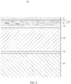
- the polymer resin layer 21 and the carbon material 22 satisfy at least one of the following relationships: the carbon material 22 is located in the polymer resin layer 21 (refer to FIG. 1 ) or in at least one surface of the polymer resin layer 21 (refer to FIG. 2 ).
- the carbon material 22 being located on at least one surface of the polymer resin layer 21 may be that the carbon material 22 is located between the polymer resin layer 21 and the first bonding layer 30, or located on a surface of the polymer resin layer 21 away from the first bonding layer 30, or located both between the polymer resin layer 21 and the first bonding layer 30 and on a surface of the polymer resin layer 21 away from the first bonding layer 30.
- the carbon material 22 may be located on an entire surface of the polymer resin layer 21, or only on a partial surface of the polymer resin layer 21.
- the carbon material 22 is located between the polymer resin layer 21 and the first bonding layer 30. Moreover, the carbon material 22 is made into a carbon layer 220 of a mesh structure through interconnection and weaving.
- the carbon material 22 acting as skeleton in the packaging film 100 is added into the packaging film 100, which can enhance the kinetic performance (for example, tensile strength and puncturing resistance) of the packaging film 100 and is conducive to reducing thickness of the entire packaging film 100.
- the energy density of the electrochemical apparatus can be increased, and because of the enhanced kinetic performance of the packaging film 100, the volume swelling of an electrode assembly in the electrochemical apparatus can be inhibited, and the deformation of the electrode assembly can be alleviated.
- the carbon material has a high heat conductivity coefficient, and therefore the heat inside the electrochemical apparatus can be conducted so as to improve safety.
- the carbon material 22 includes at least one of carbon nanotubes and carbon fibers.
- the carbon nanotubes and the carbon fibers have relatively high tensile strength, elastic modulus, oxidation resistance, and wear resistance and low thermal expansion coefficient, which is conducive to further enhancing the kinetic performance of the packaging film 100.
- a mass percentage of the carbon material 22 in the protective layer 20 is 5% to 50%.
- a percentage of resin in the polymer resin layer 21 is relatively low, and therefore the protective layer 20 cannot prevent air penetration effectively.
- the mass percentage of the carbon material 22 in the protective layer 20 is too low, effects of enhancing the kinetic performance of the packaging film 100 and inhibiting the volume swelling of the electrode assembly may not be achieved.
- the carbon material 22 is carbon nanotubes, and the carbon nanotubes are filled in the polymer resin layer 21.
- the kinetic performance of the protective layer 20 may be increased, and therefore, with the packaging film 100 used, the volume swelling of the electrode assembly can be inhibited and the deformation of the electrode assembly can be alleviated.
- the carbon material 22 in the polymer resin layer 21 may alternatively be carbon fibers.
- thickness of the protective layer 20 is 7 ⁇ m to 16 ⁇ m.
- the protective layer 20 is too thin, the air penetration cannot be prevented effectively; and when the protective layer 20 is too thick, the energy density of the electrochemical apparatus may be decreased.
- the carbon material 22 is carbon nanotubes.
- the carbon nanotubes are made into carbon fibers through interconnection in a pile diameter direction, and then the carbon fibers interconnected and woven to form the carbon layer 220.
- a structure of the carbon layer 220 obtained through interconnection and weaving of the carbon fibers made from the carbon nanotubes 22 is more compact, and compared with the structure of filling the carbon nanotubes 22 in the polymer resin layer 21, the carbon layer 220 can prevent the piercing by sharp objects more effectively, so as to further increase the puncturing resistance of the packaging film 100.
- the carbon nanotubes include at least one of multi-walled carbon nanotubes and single-walled carbon nanotubes.
- thickness of the carbon layer 220 is 2 ⁇ m to 5 ⁇ m and thickness of the polymer resin layer 21 is 7 ⁇ m to 13 ⁇ m, meaning thickness of the entire protective layer 20 is 9 ⁇ m to 18 ⁇ m.
- the carbon material 22 may further be carbon fibers, where the carbon fibers are interconnected and woven to form the carbon layer 220.
- a structure of the carbon layer 220 obtained through interconnection and weaving of the carbon fibers is more compact, and compared with the structure of filling the carbon nanotubes 22 in the polymer resin layer 21, such carbon layer 220 can prevent the piercing by sharp objects more effectively, so as to further increase the puncturing resistance of the packaging film 100.
- a material of the polymer resin layer 21 includes at least one of nylon or polyethylene terephthalate.
- the sealing layer 60 includes polypropylene. Further, the sealing layer 60 may be a polypropylene casting film, that is, a polypropylene film produced by casting process.
- a bonding material used for the first bonding layer 30 and the second bonding layer 50 includes at least one of acrylic resin, epoxy resin, or polyurethane.
- the packaging film 100 further includes a matte layer 10, the protective layer 20 is located between the matte layer 10 and the first bonding layer 30, and thickness of the matte layer 10 is 2 ⁇ m to 5 ⁇ m.
- thickness of the metal layer 40 is 24 ⁇ m to 35 ⁇ m.
- the strength thereof is insufficient.
- an overall weight of the electrochemical apparatus may be increased.
- Thickness of the sealing layer 60 is 24 ⁇ m to 35 ⁇ m.
- the sealing layer 60 is too thin, the metal layer 40 cannot be protected effectively.
- the sealing layer 60 is too thick, the heat dissipation effect and the punching effect of the packaging film 100 may be affected.
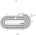
- an embodiment of this application further provides an electrochemical apparatus 200.
- the electrochemical apparatus 200 includes an electrode assembly 201 and a packaging film 100.
- the packaging film 100 is configured to package the electrode assembly 201.
- the electrochemical apparatus 200 in this application includes all apparatuses capable of generating electrochemical reactions.
- the electrochemical apparatus 200 includes all types of primary batteries, secondary batteries, fuel batteries, solar batteries, and capacitors (for example, super capacitors).
- the electrochemical apparatus 200 may be a lithium secondary battery, including a lithium metal secondary battery, a lithium-ion secondary battery, a lithium polymer secondary battery, and a lithium-ion polymer secondary battery.
- the electrode assembly 201 includes a positive electrode plate 2013, a separator 2011, and a negative electrode plate 2012.
- the separator 2011 is located between the positive electrode plate 2013 and the negative electrode plate 2012.
- the positive electrode plate 2013, the separator 2011, and the negative electrode plate 2012 are made into the electrode assembly 201 through lamination or winding.
- the negative electrode plate 2012 includes a silicon-based material.
- the silicon-based material may include at least one of silicon, silicon monoxide, a silicon-carbon composite material, or a composite material of silicon monoxide and carbon.
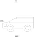
- an embodiment of this application further provides an electronic apparatus 300.
- the electronic apparatus 300 includes an electrochemical apparatus 200.
- the electronic apparatus 300 may be a consumer electronics product (for example, a mobile communication apparatus, a tablet computer, and a notebook), an electric tool, a drone, an energy storage device, a power device, or the like.
- the electronic apparatus 300 is an electric vehicle.
- negative electrode plate A negative active material including silicon-based material and graphite, conductive carbon black, and styrene butadiene rubber (SBR) were mixed at a mass ratio of 95:1.2:1.0:3.8 and dissolved in deionized water, the resulting mixture was stirred under vacuum condition until the system was uniform, and a negative slurry was obtained.
- the copper foil was used as a negative current collector.
- the negative slurry was applied onto two surfaces of the negative current collector, the resulting product was dried at 80°C-90°C, subject to cold pressing, edge shearing, part cutting, and strip shearing and then dried in vacuum for 4 h at 110°C, and a negative electrode plate was obtained.
- a mass percentage of the silicon-based material in the negative electrode plate was 15%.
- a positive active material lithium cobaltate (LiCoO 2 ), conductive carbon black, and polyvinylidene difluoride (PVDF) was mixed at a mass ratio of 96.7:1.7:1.6 and dissolved in an N-methylpyrrolidone (NMP) solvent, the resulting mixture was stirred under vacuum condition until the system was uniform, and a positive slurry was obtained.
- NMP N-methylpyrrolidone
- the aluminum foil was used as a positive current collector.
- the positive slurry was applied onto the positive current collector, the resulting product was dried at 85°C, subject to cold pressing, edge shearing, part cutting, and strip shearing, and then dried in vacuum for 4 h at 85°C, and a positive electrode plate was obtained.
- Preparation of packaging film The carbon nanotubes were added to the polymer resin to obtain a protective layer.
- the matte layer, the protective layer, the first bonding layer, the aluminum foil layer, the second bonding layer, and the sealing layer were sequentially stacked to obtain a packaging film.
- a mass percentage of the carbon nanotubes in the protective layer was 10%.
- Thickness of the protective layer was 12 ⁇ m, and thickness of the entire packaging film was 67 ⁇ m.
- Preparation of lithium-ion pouch battery A polyethylene film was used as a separator and placed between the positive electrode plate and the negative electrode plate, and then the stack was made into an electrode assembly through winding.
- the electrode assembly was loaded into the packaging film and baked in vacuum at 75°C for 10 h, injected with the electrolyte and then packaged in vacuum.
- the packaged electrode assembly was left standing for 24 h before activation processing.
- the battery was charged to 4.2 V at a constant current of 0.1C, then charged to 4.2 V at a constant voltage of 0.05C, and then discharged to 3.0 V at a constant current of 0.1C.
- the charge and discharge cycle was repeated twice. Finally, the battery was charged at a constant current of 0.1C until the charging voltage reached 3.8 V.
- a pouch battery was obtained.
- the negative electrode plate, the positive electrode plate, and the lithium-ion pouch battery in Example 2 were prepared in the same steps as those of Example 1, and details are not repeated herein.
- the preparation of the packaging film differs from that in Example 1 in that the mass percentage of the carbon nanotubes in the protective layer was 20%.
- the negative electrode plate, the positive electrode plate, and the lithium-ion pouch battery in Example 3 were prepared in the same steps as those of Example 1, and details are not repeated herein.
- the preparation of the packaging film differs from that in Example 1 in that the mass percentage of the carbon nanotubes in the protective layer was 30%.
- the negative electrode plate, the positive electrode plate, and the lithium-ion pouch battery in Example 4 were prepared in the same steps as those of Example 1, and details are not repeated herein.
- the preparation of the packaging film differs from that in Example 1 in that the mass percentage of the carbon nanotubes in the protective layer was 40%.
- the negative electrode plate, the positive electrode plate, and the lithium-ion pouch battery in Example 5 were prepared in the same steps as those of Example 1, and details are not repeated herein.
- the preparation of the packaging film differs from that in Example 1 in that the mass percentage of the carbon nanotubes in the protective layer was 50%.
- the negative electrode plate, the positive electrode plate, and the lithium-ion pouch battery in Example 6 were prepared in the same steps as those of Example 1, and details are not repeated herein.
- Preparation of packaging film The carbon nanotubes were interconnected in a pile diameter direction to form carbon fibers, and the carbon fibers were interconnected and woven to form a carbon layer.
- the matte layer, the polymer resin layer, the carbon layer, the first bonding layer, the aluminum foil layer, the second bonding layer, and the sealing layer were sequentially stacked to obtain a packaging film.
- a mass percentage of the carbon nanotubes in the protective layer was 30%, thickness of the carbon layer was 3 ⁇ m, and thickness of the polymer resin layer was 9 ⁇ m.
- the negative electrode plate, the positive electrode plate, and the lithium-ion pouch battery in Example 7 were prepared in the same steps as those of Example 6, and details are not repeated herein.
- the preparation of the packaging film differs from that in Example 6 in that the mass percentage of the carbon nanotubes in the protective layer was 50%, thickness of the carbon layer was 5 ⁇ m, and thickness of the polymer resin layer was 7 ⁇ m.
- the negative electrode plate, the positive electrode plate, and the lithium-ion pouch battery in Example 8 were prepared in the same steps as those of Example 1, and details are not repeated herein.
- the preparation of the packaging film differs from that in Example 1 in that the mass percentage of the carbon nanotubes in the protective layer was 30%, thickness of the protective layer was 10 ⁇ m, and thickness of the entire packaging film was 65 ⁇ m.
- the positive electrode plate and the lithium-ion pouch battery in Example 9 were prepared in the same steps as those of Example 8, and details are not repeated herein.
- the preparation of the negative electrode plate differs from that in Example 8 in that the mass percentage of the silicon-based material in the negative electrode plate was 20%.
- the preparation of the packaging film differs from that in Example 8 in that the mass percentage of the carbon nanotubes in the protective layer was 10%, thickness of the protective layer was 10 ⁇ m, and thickness of the entire packaging film was 67 ⁇ m.
- the positive electrode plate and the lithium-ion pouch battery in Example 10 were prepared in the same steps as those of Example 8, and details are not repeated herein.
- the preparation of the negative electrode plate differs from that in Example 8 in that the mass percentage of the silicon-based material in the negative electrode plate was 25%.
- the preparation of the packaging film differs from that in Example 8 in that a mass percentage of the carbon nanotubes in the protective layer was 16%, thickness of the protective layer was 10 ⁇ m, and thickness of the entire packaging film was 67 ⁇ m.
- the positive electrode plate and the lithium-ion pouch battery in Example 11 were prepared in the same steps as those of Example 8, and details are not repeated herein.
- the preparation of the negative electrode plate differs from that in Example 8 in that the mass percentage of the silicon-based material in the negative electrode plate was 25%.
- Preparation of packaging film The carbon nanotubes were interconnected in a pile diameter direction to form carbon fibers, and then the carbon fibers were interconnected and woven to form a carbon layer.
- the matte layer, the polymer resin layer, the carbon layer, the first bonding layer, the aluminum foil layer, the second bonding layer, and the sealing layer were sequentially stacked to obtain a packaging film.
- a mass percentage of the carbon nanotubes in the protective layer was 16%, thickness of the carbon layer was 5 ⁇ m, thickness of the polymer resin layer was 7 ⁇ m, and thickness of the entire packaging film was 67 ⁇ m.
- the positive electrode plate and the lithium-ion pouch battery in Example 12 were prepared in the same steps as those of Example 8, and details are not repeated herein.
- the preparation of the negative electrode plate differs from that in Example 8 in that a mass percentage of the silicon-based material in the negative electrode plate was 25%.
- the preparation of the packaging film differs from that in Example 8 in that the mass percentage of the carbon nanotubes in the protective layer was 27%, thickness of the protective layer was 10 ⁇ m, and thickness of the entire packaging film was 67 ⁇ m.
- the negative electrode plate, the positive electrode plate, and the lithium-ion pouch battery in Comparative Example 1 were prepared in the same steps as those of Example 1, and details are not repeated herein.
- the preparation of the packaging film differs from that in Example 1 in that the carbon nanotubes were not added to the packaging film, thickness of the protective layer was 10 ⁇ m, and thickness of the entire packaging film was 67 ⁇ m.
- the negative electrode plate, the positive electrode plate, and the lithium-ion pouch battery in Comparative Example 2 were prepared in the same steps as those of Example 1, and details are not repeated herein.
- the preparation of the packaging film differs from that in Example 1 in that the carbon nanotubes were not added to the packaging film, thickness of the protective layer was 10 ⁇ m, and thickness of the entire packaging film was 65 ⁇ m.
- the packaging films prepared in Examples 1 to 12 and Comparative Examples 1 and 2 were subject to tensile strength test and puncturing resistance test, and the pouch batteries prepared in Example 1 to 12 and Comparative Examples 1 and 2 were subject to full-charge swelling rate test, and the test results were recorded in Table 1.
- the tensile strength test was done using a multifunctional tensile testing machine, and the test procedure included: cutting a packaging film into samples with a length of 150 mm and width of 15 mm, mounting the sample to two fixtures of the tensile testing machine, and setting an initial tensile length to be 50 mm, and performing tensile test at a tensile speed of 5 mm/min until the sample was broken.
- the maximum tensile force at which the sample was broken was recorded.
- the ratio of the maximum tensile force to the cross-sectional area of the sample (which can be calculated by multiplying the width and thickness of the sample) was the tensile strength.
- the puncturing resistance test was done using a multifunctional tensile testing machine, and the test procedure included: piercing the packaging film at a speed of 50 mm/min using a needle with a spherical radius of 0.5 mm, and reading a value of the tensile testing machine when the needle pierced the packaging film, where the value was the puncturing resistance.
- the step of testing full-charge battery swelling rate included: measuring thickness of a fresh battery in 50% state of charge (50% SOC) using a spiral micrometer at 25°C; when the battery cell was in 100% state of charge (100% SOC) after 400 cycles, testing thickness of the battery at that point still using the spiral micrometer; and comparing the thickness at the point with the initial thickness of the fresh battery in 50% state of charge to obtain the swelling rate of the battery in 100% state of charge (50% SOC) at the point.
- Examples 1 to 5 with the increase of the percentage of carbon nanotubes, the tensile strength and puncturing resistance of the packaging film are gradually increased, and the swelling rate of the entire pouch battery is decreased. However, when the percentage of carbon nanotubes is increased to a given extent (that is, from 40% to 50%), the swelling rate of the pouch battery is less inhibited.
- the add method 1 and add method 2 are used for the carbon nanotubes in Example 3 and Example 6 respectively, and given the same percentage of carbon nanotubes, the two have roughly the same tensile strength and full-charge swelling rate.
- the add method 1 and add method 2 are used for the carbon nanotubes in Example 5 and Example 7 respectively, and given the same percentage of carbon nanotubes, the two have roughly the same tensile strength and full-charge swelling rate. This, therefore, proves that different add methods do not have much effect on the tensile strength and full-charge swelling rate of the packaging film.
- the puncturing resistance of the packaging film in Example 6 is increased.
- the puncturing resistance of the packaging film in Example 7 is also increased. This is because the carbon layer is obtained through interconnection and weaving of carbon fibers made from carbon nanotubes, and the carbon layer has a relatively compact structure, which can prevent piercing by sharp objects.
- carbon nanotubes are added to the polymer resin layer in Example 8, and therefore not only the swelling of the battery can be inhibited, but also the thickness of the entire packaging film can be decreased, which is beneficial to increasing the energy density of the battery.
- Example 10 the percentage of silicon-based material in the negative electrode plate is increased in Examples 10 to 12, and therefore if the full-charge swelling rate is required to be less than 10%, the percentage of carbon nanotubes should be increased accordingly using either add method 1 (as in Example 10 and Example 12) or add method 2 (as in Example 11).
- add method 1 as in Example 10 and Example 12
- add method 2 as in Example 11.
- the comparison between Example 10 and Example 12 shows that when the percentage of the silicon-based material in the negative electrode plate increases by the same gradient, the percentage of the carbon nanotubes in the packaging film needs to increase by a higher gradient in order to keep the full-charge swelling rate less than 10%.
Landscapes
- Chemical & Material Sciences (AREA)
- Chemical Kinetics & Catalysis (AREA)
- Electrochemistry (AREA)
- General Chemical & Material Sciences (AREA)
- Inorganic Chemistry (AREA)
- Composite Materials (AREA)
- Engineering & Computer Science (AREA)
- Textile Engineering (AREA)
- Materials Engineering (AREA)
- Secondary Cells (AREA)
- Sealing Battery Cases Or Jackets (AREA)
Abstract
Description
- This application relates to the battery field, and in particular, to a packaging film, an electrochemical apparatus, and an electronic apparatus.
- Silicon has a promising application prospect in lithium-ion batteries for its high theoretical lithiation gram capacity of 4200 mAh/g and abundant reserves on the earth. However, large volume swelling of silicon particles occurs during cycling, which leads to pulverization of silicon particles, and reduces the adhesion between the active material layer and current collector in the negative electrode plate, resulting in detachment of the active material layer, thus degrading cycling performance of the lithium-ion battery.
- Especially for pouch batteries, packaging films cannot inhibit the swelling of silicon particles. When silicon particles swell, not only the cycling performance of the batteries is affected, but also the sealing edges of the packaging films are easily broken, resulting in the risk of electrolyte leakage.
- In order to overcome the preceding shortcomings in the prior art, it is necessary to provide a packaging film that can inhibit the swelling of silicon particles.
- In addition, it is also necessary to provide an electrochemical apparatus including the foregoing packaging film.
- Moreover, it is also necessary to provide an electronic apparatus including the foregoing electrochemical apparatus.
- This application provides a packaging film, including a protective layer, a first bonding layer, a metal layer, a second bonding layer, and a sealing layer that are sequentially stacked.
- In this application, a carbon material acting as skeleton in the packaging film is added into the packaging film, which can enhance the kinetic performance of the packaging film and is conducive to reducing thickness of the entire packaging film. When such packaging film is applied to an electrochemical apparatus, the energy density of the electrochemical apparatus can be increased, and because of the enhanced kinetic performance of the packaging film, the volume swelling of an electrode assembly in the electrochemical apparatus can be inhibited, and the deformation of the electrode assembly can be alleviated.
- In some embodiments of this application, the polymer resin layer and the carbon material satisfy at least one of the following relationships: the carbon material is located in the polymer resin layer or in at least one surface of the polymer resin layer.
- In some embodiments of this application, a mass percentage of the carbon material in the protective layer is 5% to 50%. When the mass percentage of the carbon material in the protective layer is too high, the protective layer cannot prevent air penetration effectively. When the mass percentage of the carbon material in the protective layer is too low, effects of enhancing the kinetic performance of the packaging film and inhibiting the volume swelling of the electrode assembly may not be achieved.
- In some embodiments of this application, the carbon material includes at least one of carbon nanotubes and carbon fibers. The carbon nanotubes and the carbon fibers have relatively high tensile strength, elastic modulus, oxidation resistance, and wear resistance and low thermal expansion coefficient, which is conducive to further enhancing the kinetic performance of the packaging film.
- In some embodiments of this application, the carbon material includes the carbon fibers, where the carbon fibers are interconnected and woven to form a carbon layer, and the carbon layer is located between the polymer resin layer and the first bonding layer. A structure of the carbon layer obtained through interconnection and weaving of the carbon fibers is relatively compact, and compared with the structure of filling carbon fibers in the polymer resin layer, such carbon layer can prevent the piercing by sharp objects more effectively, so as to further increase the puncturing resistance of the packaging film.
- In some embodiments of this application, thickness of the carbon layer is 2 µm to 5 µm.
- In some embodiments of this application, the carbon nanotubes include at least one of multi-walled carbon nanotubes and single-walled carbon nanotubes.
- In some embodiments of this application, thickness of the protective layer is 7 µm to 16 µm.
- In some embodiments of this application, the polymer resin includes at least one of nylon or polyethylene terephthalate.
- In some embodiments of this application, the packaging film further includes a matte layer, the protective layer is located between the matte layer and the first bonding layer, and thickness of the matte layer is 2 µm to 5 µm.
- In some embodiments of this application, thickness of the metal layer is 24 µm to 35 µm, and thickness of the sealing layer is 24 µm to 35 µm.
- In some embodiments of this application, the sealing layer includes polypropylene.
- This application further provides an electrochemical apparatus, including an electrode assembly. The electrochemical apparatus further includes the foregoing packaging film, and the packaging film is configured to package the electrode assembly. The packaging film used, the energy density of the electrochemical apparatus can be increased, and because of the enhanced kinetic performance of the packaging film, the volume swelling of the electrode assembly in the electrochemical apparatus can be inhibited, and the deformation of the electrode assembly can be alleviated. In addition, the carbon material has a high heat conductivity coefficient, and therefore the heat inside the electrochemical apparatus can be conducted so as to improve safety.
- In some embodiments of this application, the electrode assembly includes a positive electrode plate, a separator, and a negative electrode plate, where the separator is located between the positive electrode plate and the negative electrode plate, the positive electrode plate, the separator, and the negative electrode plate are made into the electrode assembly through lamination or winding, and the negative electrode plate includes a silicon-based material.
- In some embodiments of this application, the silicon-based material includes at least one of silicon, silicon monoxide, a silicon-carbon composite material, or a composite material of silicon monoxide and carbon.
- This application further provides an electronic apparatus, including the foregoing electrochemical apparatus.
-
-
FIG. 1 is a schematic cross-sectional view of a packaging film according to an embodiment of this application. -
FIG. 2 is a schematic cross-sectional view of a packaging film according to another embodiment of this application. -
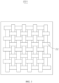
FIG. 3 is a top view of a carbon layer of the packaging film shown inFIG. 2 . -
FIG. 4 is a schematic structural diagram of an electrochemical apparatus according to an embodiment of this application. -
FIG. 5 is a schematic structural diagram of an electronic apparatus according to an embodiment of this application. -
Matte layer 10 Protective layer 20 Polymer resin layer 21 Carbon material 22 First bonding layer 30 Metal layer 40 Second bonding layer 50 Sealing layer 60 Packaging film 100 Electrochemical apparatus 200 Electrode assembly 201 Carbon layer 220 Electronic apparatus 300 Separator 2011 Negative electrode plate 2012 Positive electrode plate 2013 - This application will be further described with reference to the accompanying drawings in the following embodiments.
- In order to help understand the foregoing objectives, features, and advantages of this application more clearly, the following describes this application in detail with reference to the accompanying drawings and embodiments. It should be noted that, without conflict, the embodiments and features in the embodiments of this application may be combined with each other. Many specific details are illustrated in the following descriptions to facilitate a full understanding of this application, and the embodiments described are only some rather than all of the embodiments of this application. All other embodiments obtained by a person of ordinary skill in the art based on the embodiments of this application without creative efforts shall fall within the protection scope of this application.
- Unless otherwise defined, all technical and scientific terms used herein shall have the same meanings as commonly understood by those skilled in the art to which this application relates. The terms used in this specification of this application are intended to merely describe embodiments rather than to limit this application. The terms "and/or" used herein include all and arbitrary combinations of one or more related listed items.
- In the embodiments of this application, in order to facilitate describing not limiting this application, the term "connect" as used in the specification and claims of this application is not limited to a physical or mechanical connection, whether direct or indirect. "Upper", "lower", "above", "below", "left", and "right" are only used to represent the relative position relationship. When the absolute position of the described object changes, the relative position relationship also changes accordingly.
- Referring to
FIG 1 andFIG. 2 , an embodiment of this application provides apackaging film 100, including aprotective layer 20, afirst bonding layer 30, ametal layer 40, asecond bonding layer 50, and asealing layer 60 that are sequentially stacked. Theprotective layer 20 includes apolymer resin layer 21 and acarbon material 22. - The
polymer resin layer 21 is configured to protect themetal layer 40 in thepackaging film 100, to prevent themetal layer 40 from damage caused by an external force and to prevent the air penetration of the external environment, so as to maintain the electrochemical apparatus in a water and oxygen free environment. Themetal layer 40 is configured to prevent moisture penetration from the external environment and to prevent the electrochemical apparatus from damage caused by an external force. In an embodiment, themetal layer 40 may be specifically an aluminum foil layer. The sealinglayer 60 is configured to package thepackaging film 100 to prevent thepackaging film 100 from being dissolved or swollen by an organic solvent inside the electrochemical apparatus. Thesealing layer 60 is further configured to prevent the electrolyte inside the electrochemical apparatus from being in contact with themetal layer 40, resulting in corrosion of themetal layer 40. Thefirst bonding layer 30 is configured to bond theprotective layer 20 and themetal layer 40, and thesecond bonding layer 50 is configured to bond themetal layer 40 and thesealing layer 60, so as to prevent two adjacent layers from detachment. - The
polymer resin layer 21 and thecarbon material 22 satisfy at least one of the following relationships: thecarbon material 22 is located in the polymer resin layer 21 (refer toFIG. 1 ) or in at least one surface of the polymer resin layer 21 (refer toFIG. 2 ). Thecarbon material 22 being located on at least one surface of thepolymer resin layer 21 may be that thecarbon material 22 is located between thepolymer resin layer 21 and thefirst bonding layer 30, or located on a surface of thepolymer resin layer 21 away from thefirst bonding layer 30, or located both between thepolymer resin layer 21 and thefirst bonding layer 30 and on a surface of thepolymer resin layer 21 away from thefirst bonding layer 30. Further, thecarbon material 22 may be located on an entire surface of thepolymer resin layer 21, or only on a partial surface of thepolymer resin layer 21. - As shown in
FIG. 2 , thecarbon material 22 is located between thepolymer resin layer 21 and thefirst bonding layer 30. Moreover, thecarbon material 22 is made into acarbon layer 220 of a mesh structure through interconnection and weaving. - In this application, the
carbon material 22 acting as skeleton in thepackaging film 100 is added into thepackaging film 100, which can enhance the kinetic performance (for example, tensile strength and puncturing resistance) of thepackaging film 100 and is conducive to reducing thickness of theentire packaging film 100. When the foregoingpackaging film 100 is applied to the electrochemical apparatus, the energy density of the electrochemical apparatus can be increased, and because of the enhanced kinetic performance of thepackaging film 100, the volume swelling of an electrode assembly in the electrochemical apparatus can be inhibited, and the deformation of the electrode assembly can be alleviated. In addition, the carbon material has a high heat conductivity coefficient, and therefore the heat inside the electrochemical apparatus can be conducted so as to improve safety. - In some embodiments, the
carbon material 22 includes at least one of carbon nanotubes and carbon fibers. The carbon nanotubes and the carbon fibers have relatively high tensile strength, elastic modulus, oxidation resistance, and wear resistance and low thermal expansion coefficient, which is conducive to further enhancing the kinetic performance of thepackaging film 100. - In some embodiments, a mass percentage of the
carbon material 22 in theprotective layer 20 is 5% to 50%. When the mass percentage of thecarbon material 22 in theprotective layer 20 is too high, a percentage of resin in thepolymer resin layer 21 is relatively low, and therefore theprotective layer 20 cannot prevent air penetration effectively. When the mass percentage of thecarbon material 22 in theprotective layer 20 is too low, effects of enhancing the kinetic performance of thepackaging film 100 and inhibiting the volume swelling of the electrode assembly may not be achieved. - As shown in
FIG. 1 , in an embodiment, thecarbon material 22 is carbon nanotubes, and the carbon nanotubes are filled in thepolymer resin layer 21. In this way, the kinetic performance of theprotective layer 20 may be increased, and therefore, with thepackaging film 100 used, the volume swelling of the electrode assembly can be inhibited and the deformation of the electrode assembly can be alleviated. Certainly, in other embodiments, thecarbon material 22 in thepolymer resin layer 21 may alternatively be carbon fibers. - Further, thickness of the
protective layer 20 is 7 µm to 16 µm. When theprotective layer 20 is too thin, the air penetration cannot be prevented effectively; and when theprotective layer 20 is too thick, the energy density of the electrochemical apparatus may be decreased. - As shown in
FIG. 2 andFIG. 3 , in another embodiment, thecarbon material 22 is carbon nanotubes. The carbon nanotubes are made into carbon fibers through interconnection in a pile diameter direction, and then the carbon fibers interconnected and woven to form thecarbon layer 220. A structure of thecarbon layer 220 obtained through interconnection and weaving of the carbon fibers made from thecarbon nanotubes 22 is more compact, and compared with the structure of filling thecarbon nanotubes 22 in thepolymer resin layer 21, thecarbon layer 220 can prevent the piercing by sharp objects more effectively, so as to further increase the puncturing resistance of thepackaging film 100. In some embodiments, the carbon nanotubes include at least one of multi-walled carbon nanotubes and single-walled carbon nanotubes. - Further, thickness of the
carbon layer 220 is 2 µm to 5 µm and thickness of thepolymer resin layer 21 is 7 µm to 13 µm, meaning thickness of the entireprotective layer 20 is 9 µm to 18 µm. - In another embodiment, the
carbon material 22 may further be carbon fibers, where the carbon fibers are interconnected and woven to form thecarbon layer 220. A structure of thecarbon layer 220 obtained through interconnection and weaving of the carbon fibers is more compact, and compared with the structure of filling thecarbon nanotubes 22 in thepolymer resin layer 21,such carbon layer 220 can prevent the piercing by sharp objects more effectively, so as to further increase the puncturing resistance of thepackaging film 100. - In some embodiments, a material of the
polymer resin layer 21 includes at least one of nylon or polyethylene terephthalate. Thesealing layer 60 includes polypropylene. Further, thesealing layer 60 may be a polypropylene casting film, that is, a polypropylene film produced by casting process. A bonding material used for thefirst bonding layer 30 and thesecond bonding layer 50 includes at least one of acrylic resin, epoxy resin, or polyurethane. - In some embodiments, the
packaging film 100 further includes amatte layer 10, theprotective layer 20 is located between thematte layer 10 and thefirst bonding layer 30, and thickness of thematte layer 10 is 2 µm to 5 µm. - Moreover, thickness of the
metal layer 40 is 24 µm to 35 µm. When themetal layer 40 is too thin, the strength thereof is insufficient. When themetal layer 40 is too thick, an overall weight of the electrochemical apparatus may be increased. - Thickness of the
sealing layer 60 is 24 µm to 35 µm. When thesealing layer 60 is too thin, themetal layer 40 cannot be protected effectively. When thesealing layer 60 is too thick, the heat dissipation effect and the punching effect of thepackaging film 100 may be affected. - Referring to
FIG. 4 , an embodiment of this application further provides anelectrochemical apparatus 200. Theelectrochemical apparatus 200 includes anelectrode assembly 201 and apackaging film 100. Thepackaging film 100 is configured to package theelectrode assembly 201. Theelectrochemical apparatus 200 in this application includes all apparatuses capable of generating electrochemical reactions. Specifically, theelectrochemical apparatus 200 includes all types of primary batteries, secondary batteries, fuel batteries, solar batteries, and capacitors (for example, super capacitors). Optionally, theelectrochemical apparatus 200 may be a lithium secondary battery, including a lithium metal secondary battery, a lithium-ion secondary battery, a lithium polymer secondary battery, and a lithium-ion polymer secondary battery. - In an embodiment, the
electrode assembly 201 includes apositive electrode plate 2013, aseparator 2011, and anegative electrode plate 2012. Theseparator 2011 is located between thepositive electrode plate 2013 and thenegative electrode plate 2012. Thepositive electrode plate 2013, theseparator 2011, and thenegative electrode plate 2012 are made into theelectrode assembly 201 through lamination or winding. Thenegative electrode plate 2012 includes a silicon-based material. - Further, the silicon-based material may include at least one of silicon, silicon monoxide, a silicon-carbon composite material, or a composite material of silicon monoxide and carbon.
- Referring to
FIG. 5 , an embodiment of this application further provides anelectronic apparatus 300. Theelectronic apparatus 300 includes anelectrochemical apparatus 200. Theelectronic apparatus 300 may be a consumer electronics product (for example, a mobile communication apparatus, a tablet computer, and a notebook), an electric tool, a drone, an energy storage device, a power device, or the like. Referring toFIG. 5 , in an embodiment, theelectronic apparatus 300 is an electric vehicle. - This application is described in the following by using specific examples and comparative examples.
- Preparation of negative electrode plate: A negative active material including silicon-based material and graphite, conductive carbon black, and styrene butadiene rubber (SBR) were mixed at a mass ratio of 95:1.2:1.0:3.8 and dissolved in deionized water, the resulting mixture was stirred under vacuum condition until the system was uniform, and a negative slurry was obtained. The copper foil was used as a negative current collector. The negative slurry was applied onto two surfaces of the negative current collector, the resulting product was dried at 80°C-90°C, subject to cold pressing, edge shearing, part cutting, and strip shearing and then dried in vacuum for 4 h at 110°C, and a negative electrode plate was obtained. A mass percentage of the silicon-based material in the negative electrode plate was 15%.
- Preparation of positive electrode plate: A positive active material lithium cobaltate (LiCoO2), conductive carbon black, and polyvinylidene difluoride (PVDF) was mixed at a mass ratio of 96.7:1.7:1.6 and dissolved in an N-methylpyrrolidone (NMP) solvent, the resulting mixture was stirred under vacuum condition until the system was uniform, and a positive slurry was obtained. The aluminum foil was used as a positive current collector. The positive slurry was applied onto the positive current collector, the resulting product was dried at 85°C, subject to cold pressing, edge shearing, part cutting, and strip shearing, and then dried in vacuum for 4 h at 85°C, and a positive electrode plate was obtained.
- Preparation of packaging film: The carbon nanotubes were added to the polymer resin to obtain a protective layer. The matte layer, the protective layer, the first bonding layer, the aluminum foil layer, the second bonding layer, and the sealing layer were sequentially stacked to obtain a packaging film. A mass percentage of the carbon nanotubes in the protective layer was 10%. Thickness of the protective layer was 12 µm, and thickness of the entire packaging film was 67 µm.
- Preparation of lithium-ion pouch battery: A polyethylene film was used as a separator and placed between the positive electrode plate and the negative electrode plate, and then the stack was made into an electrode assembly through winding. The electrode assembly was loaded into the packaging film and baked in vacuum at 75°C for 10 h, injected with the electrolyte and then packaged in vacuum. The packaged electrode assembly was left standing for 24 h before activation processing. In the activation processing, the battery was charged to 4.2 V at a constant current of 0.1C, then charged to 4.2 V at a constant voltage of 0.05C, and then discharged to 3.0 V at a constant current of 0.1C. The charge and discharge cycle was repeated twice. Finally, the battery was charged at a constant current of 0.1C until the charging voltage reached 3.8 V. A pouch battery was obtained.
- The negative electrode plate, the positive electrode plate, and the lithium-ion pouch battery in Example 2 were prepared in the same steps as those of Example 1, and details are not repeated herein.
- The preparation of the packaging film differs from that in Example 1 in that the mass percentage of the carbon nanotubes in the protective layer was 20%.
- The negative electrode plate, the positive electrode plate, and the lithium-ion pouch battery in Example 3 were prepared in the same steps as those of Example 1, and details are not repeated herein.
- The preparation of the packaging film differs from that in Example 1 in that the mass percentage of the carbon nanotubes in the protective layer was 30%.
- The negative electrode plate, the positive electrode plate, and the lithium-ion pouch battery in Example 4 were prepared in the same steps as those of Example 1, and details are not repeated herein.
- The preparation of the packaging film differs from that in Example 1 in that the mass percentage of the carbon nanotubes in the protective layer was 40%.
- The negative electrode plate, the positive electrode plate, and the lithium-ion pouch battery in Example 5 were prepared in the same steps as those of Example 1, and details are not repeated herein.
- The preparation of the packaging film differs from that in Example 1 in that the mass percentage of the carbon nanotubes in the protective layer was 50%.
- The negative electrode plate, the positive electrode plate, and the lithium-ion pouch battery in Example 6 were prepared in the same steps as those of Example 1, and details are not repeated herein.
- Preparation of packaging film: The carbon nanotubes were interconnected in a pile diameter direction to form carbon fibers, and the carbon fibers were interconnected and woven to form a carbon layer. The matte layer, the polymer resin layer, the carbon layer, the first bonding layer, the aluminum foil layer, the second bonding layer, and the sealing layer were sequentially stacked to obtain a packaging film. A mass percentage of the carbon nanotubes in the protective layer (the protective layer included a polymer resin layer and a carbon mesh layer) was 30%, thickness of the carbon layer was 3 µm, and thickness of the polymer resin layer was 9 µm.
- The negative electrode plate, the positive electrode plate, and the lithium-ion pouch battery in Example 7 were prepared in the same steps as those of Example 6, and details are not repeated herein.
- The preparation of the packaging film differs from that in Example 6 in that the mass percentage of the carbon nanotubes in the protective layer was 50%, thickness of the carbon layer was 5 µm, and thickness of the polymer resin layer was 7 µm.
- The negative electrode plate, the positive electrode plate, and the lithium-ion pouch battery in Example 8 were prepared in the same steps as those of Example 1, and details are not repeated herein.
- The preparation of the packaging film differs from that in Example 1 in that the mass percentage of the carbon nanotubes in the protective layer was 30%, thickness of the protective layer was 10 µm, and thickness of the entire packaging film was 65 µm.
- The positive electrode plate and the lithium-ion pouch battery in Example 9 were prepared in the same steps as those of Example 8, and details are not repeated herein.
- The preparation of the negative electrode plate differs from that in Example 8 in that the mass percentage of the silicon-based material in the negative electrode plate was 20%.
- The preparation of the packaging film differs from that in Example 8 in that the mass percentage of the carbon nanotubes in the protective layer was 10%, thickness of the protective layer was 10 µm, and thickness of the entire packaging film was 67 µm.
- The positive electrode plate and the lithium-ion pouch battery in Example 10 were prepared in the same steps as those of Example 8, and details are not repeated herein.
- The preparation of the negative electrode plate differs from that in Example 8 in that the mass percentage of the silicon-based material in the negative electrode plate was 25%.
- The preparation of the packaging film differs from that in Example 8 in that a mass percentage of the carbon nanotubes in the protective layer was 16%, thickness of the protective layer was 10 µm, and thickness of the entire packaging film was 67 µm.
- The positive electrode plate and the lithium-ion pouch battery in Example 11 were prepared in the same steps as those of Example 8, and details are not repeated herein.
- The preparation of the negative electrode plate differs from that in Example 8 in that the mass percentage of the silicon-based material in the negative electrode plate was 25%.
- Preparation of packaging film: The carbon nanotubes were interconnected in a pile diameter direction to form carbon fibers, and then the carbon fibers were interconnected and woven to form a carbon layer. The matte layer, the polymer resin layer, the carbon layer, the first bonding layer, the aluminum foil layer, the second bonding layer, and the sealing layer were sequentially stacked to obtain a packaging film. A mass percentage of the carbon nanotubes in the protective layer was 16%, thickness of the carbon layer was 5 µm, thickness of the polymer resin layer was 7 µm, and thickness of the entire packaging film was 67 µm.
- The positive electrode plate and the lithium-ion pouch battery in Example 12 were prepared in the same steps as those of Example 8, and details are not repeated herein.
- The preparation of the negative electrode plate differs from that in Example 8 in that a mass percentage of the silicon-based material in the negative electrode plate was 25%.
- The preparation of the packaging film differs from that in Example 8 in that the mass percentage of the carbon nanotubes in the protective layer was 27%, thickness of the protective layer was 10 µm, and thickness of the entire packaging film was 67 µm.
- The negative electrode plate, the positive electrode plate, and the lithium-ion pouch battery in Comparative Example 1 were prepared in the same steps as those of Example 1, and details are not repeated herein.
- The preparation of the packaging film differs from that in Example 1 in that the carbon nanotubes were not added to the packaging film, thickness of the protective layer was 10 µm, and thickness of the entire packaging film was 67 µm.
- The negative electrode plate, the positive electrode plate, and the lithium-ion pouch battery in Comparative Example 2 were prepared in the same steps as those of Example 1, and details are not repeated herein.
- The preparation of the packaging film differs from that in Example 1 in that the carbon nanotubes were not added to the packaging film, thickness of the protective layer was 10 µm, and thickness of the entire packaging film was 65 µm.
- The packaging films prepared in Examples 1 to 12 and Comparative Examples 1 and 2 were subject to tensile strength test and puncturing resistance test, and the pouch batteries prepared in Example 1 to 12 and Comparative Examples 1 and 2 were subject to full-charge swelling rate test, and the test results were recorded in Table 1.
- The tensile strength test was done using a multifunctional tensile testing machine, and the test procedure included: cutting a packaging film into samples with a length of 150 mm and width of 15 mm, mounting the sample to two fixtures of the tensile testing machine, and setting an initial tensile length to be 50 mm, and performing tensile test at a tensile speed of 5 mm/min until the sample was broken. The maximum tensile force at which the sample was broken was recorded. The ratio of the maximum tensile force to the cross-sectional area of the sample (which can be calculated by multiplying the width and thickness of the sample) was the tensile strength.
- The puncturing resistance test was done using a multifunctional tensile testing machine, and the test procedure included: piercing the packaging film at a speed of 50 mm/min using a needle with a spherical radius of 0.5 mm, and reading a value of the tensile testing machine when the needle pierced the packaging film, where the value was the puncturing resistance.
- The step of testing full-charge battery swelling rate included: measuring thickness of a fresh battery in 50% state of charge (50% SOC) using a spiral micrometer at 25°C; when the battery cell was in 100% state of charge (100% SOC) after 400 cycles, testing thickness of the battery at that point still using the spiral micrometer; and comparing the thickness at the point with the initial thickness of the fresh battery in 50% state of charge to obtain the swelling rate of the battery in 100% state of charge (50% SOC) at the point.

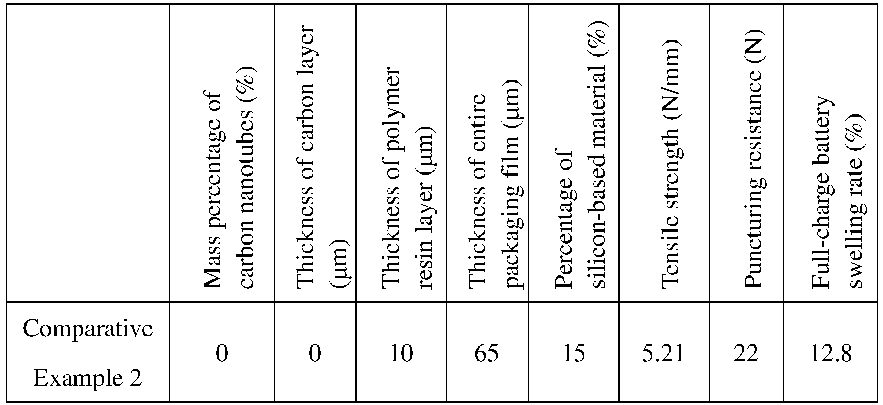
- It can be learned from the test results shown in Table 1 that, as compared with the Comparative Examples 1 and 2, because the carbon nanotubes are added to the polymer resin layer in Examples 1 to 5, the volume swelling of the pouch battery is inhibited, and the full-charge swelling rate is lower. As compared with the Comparative Examples 1 and 2, because the carbon layer obtained through weaving of carbon nanotubes is added to the surface of the polymer resin layer in Example 6 and Example 7, the swelling rate of the pouch battery is relatively small. Therefore, either adding the carbon nanotubes to the polymer resin layer (hereinafter referred to as add method 1) or adding carbon layer obtained through weaving of carbon nanotubes on the surface of the polymer resin layer (hereinafter referred to as add method 2) performs well in inhibiting the swelling of the pouch battery.
- In Examples 1 to 5, with the increase of the percentage of carbon nanotubes, the tensile strength and puncturing resistance of the packaging film are gradually increased, and the swelling rate of the entire pouch battery is decreased. However, when the percentage of carbon nanotubes is increased to a given extent (that is, from 40% to 50%), the swelling rate of the pouch battery is less inhibited.
- The add method 1 and add method 2 are used for the carbon nanotubes in Example 3 and Example 6 respectively, and given the same percentage of carbon nanotubes, the two have roughly the same tensile strength and full-charge swelling rate. Similarly, the add method 1 and add method 2 are used for the carbon nanotubes in Example 5 and Example 7 respectively, and given the same percentage of carbon nanotubes, the two have roughly the same tensile strength and full-charge swelling rate. This, therefore, proves that different add methods do not have much effect on the tensile strength and full-charge swelling rate of the packaging film. However, as compared with Example 3, the puncturing resistance of the packaging film in Example 6 is increased. Similarly, as compared with Example 5, the puncturing resistance of the packaging film in Example 7 is also increased. This is because the carbon layer is obtained through interconnection and weaving of carbon fibers made from carbon nanotubes, and the carbon layer has a relatively compact structure, which can prevent piercing by sharp objects.
- As compared with Comparative Example 1, carbon nanotubes are added to the polymer resin layer in Example 8, and therefore not only the swelling of the battery can be inhibited, but also the thickness of the entire packaging film can be decreased, which is beneficial to increasing the energy density of the battery.
- As compared with Example 9, the percentage of silicon-based material in the negative electrode plate is increased in Examples 10 to 12, and therefore if the full-charge swelling rate is required to be less than 10%, the percentage of carbon nanotubes should be increased accordingly using either add method 1 (as in Example 10 and Example 12) or add method 2 (as in Example 11). The comparison between Example 10 and Example 12 shows that when the percentage of the silicon-based material in the negative electrode plate increases by the same gradient, the percentage of the carbon nanotubes in the packaging film needs to increase by a higher gradient in order to keep the full-charge swelling rate less than 10%.
- The foregoing embodiments are only intended to describe rather than limit the technical solution of this application, although this application is explained in detail with reference to the foregoing preferred embodiments, person of ordinary skill in the art should understand that any modification or equivalent replacement of the technical solution in this application shall not departing from the spirit and scope of the technical solution of this application.
Claims (16)
- A packaging film, comprising a protective layer, a first bonding layer, a metal layer, a second bonding layer, and a sealing layer that are sequentially stacked, characterized in that the protective layer comprises a polymer resin layer and a carbon material.
- The packaging film according to claim 1, characterized in that the polymer resin layer and the carbon material satisfy at least one of the following relationships: the carbon material is located in the polymer resin layer or in at least one surface of the polymer resin layer.
- The packaging film according to claim 1, characterized in that a mass percentage of the carbon material in the protective layer is 5% to 50%.
- The packaging film according to claim 1, characterized in that the carbon material comprises at least one of carbon nanotubes and carbon fibers.
- The packaging film according to claim 4, characterized in that the carbon material comprises the carbon fibers, wherein the carbon fibers are interconnected and woven to form a carbon layer, and the carbon layer is located between the polymer resin layer and the first bonding layer.
- The packaging film according to claim 5, characterized in that thickness of the carbon layer is 2 µm to 5 µm.
- The packaging film according to claim 4, characterized in that the carbon nanotubes comprise at least one of multi-walled carbon nanotubes and single-walled carbon nanotubes.
- The packaging film according to claim 1, characterized in that thickness of the protective layer is 7 µm to 16 µm.
- The packaging film according to claim 1, characterized in that a material of the polymer resin layer comprises at least one of nylon or polyethylene terephthalate.
- The packaging film according to claim 1, characterized in that the packaging film further comprises a matte layer, the protective layer is located between the matte layer and the first bonding layer, and thickness of the matte layer is 2 µm to 5 µm.
- The packaging film according to claim 1, characterized in that thickness of the metal layer is 24 µm to 35 µm, and thickness of the sealing layer is 24 µm to 35 µm.
- The packaging film according to claim 1, characterized in that the sealing layer comprises polypropylene.
- An electrochemical apparatus, comprising an electrode assembly, characterized in that the electrochemical apparatus further comprises the packaging film according to any one of claims 1 to 12, and the packaging film is configured to package the electrode assembly.
- The electrochemical apparatus according to claim 13, characterized in that the electrode assembly comprises a positive electrode plate, a separator, and a negative electrode plate, wherein the separator is located between the positive electrode plate and the negative electrode plate, the positive electrode plate, the separator, and the negative electrode plate are made into the electrode assembly through lamination or winding, and the negative electrode plate comprises a silicon-based material.
- The electrochemical apparatus according to claim 14, characterized in that the silicon-based material comprises at least one of silicon, silicon monoxide, a silicon-carbon composite material, or a composite material of silicon monoxide and carbon.
- An electronic apparatus, characterized by comprising the electrochemical apparatus according to any one of claims 13 to 15.
Applications Claiming Priority (1)
| Application Number | Priority Date | Filing Date | Title |
|---|---|---|---|
| PCT/CN2020/090668 WO2021227073A1 (en) | 2020-05-15 | 2020-05-15 | Packaging film, electrochemical apparatus, and electronic apparatus |
Publications (2)
| Publication Number | Publication Date |
|---|---|
| EP4152487A1 true EP4152487A1 (en) | 2023-03-22 |
| EP4152487A4 EP4152487A4 (en) | 2023-07-19 |
Family
ID=78525936
Family Applications (1)
| Application Number | Title | Priority Date | Filing Date |
|---|---|---|---|
| EP20935516.3A Pending EP4152487A4 (en) | 2020-05-15 | 2020-05-15 | PACKAGING FILM, ELECTROCHEMICAL DEVICE AND ELECTRONIC DEVICE |
Country Status (4)
| Country | Link |
|---|---|
| US (1) | US20230080891A1 (en) |
| EP (1) | EP4152487A4 (en) |
| CN (1) | CN115461912B (en) |
| WO (1) | WO2021227073A1 (en) |
Families Citing this family (6)
| Publication number | Priority date | Publication date | Assignee | Title |
|---|---|---|---|---|
| CN114497833A (en) * | 2020-11-11 | 2022-05-13 | 华为技术有限公司 | Battery packaging film, preparation method of battery packaging film and electronic equipment |
| CN114335827B (en) * | 2021-12-20 | 2024-04-02 | 广东广麟材耀新能源材料有限公司 | Anti-cracking aluminum plastic film |
| KR102763173B1 (en) * | 2023-04-06 | 2025-02-07 | 율촌화학 주식회사 | Film for cell pouch with minimal deformation of laminate and manufacturing method thereof |
| KR102675023B1 (en) * | 2023-04-06 | 2024-06-14 | 율촌화학 주식회사 | Film for cell pouch and manufacturing method thereof |
| CN119050567A (en) * | 2024-09-19 | 2024-11-29 | 宁德新能源科技有限公司 | Packaging bag, secondary battery and electronic equipment |
| CN118899596A (en) * | 2024-09-29 | 2024-11-05 | 宁德时代新能源科技股份有限公司 | Solid-state battery cell and method for manufacturing the same |
Family Cites Families (23)
| Publication number | Priority date | Publication date | Assignee | Title |
|---|---|---|---|---|
| US7150934B2 (en) * | 2002-03-26 | 2006-12-19 | Matsushita Electric Industrial Co., Ltd. | Electrolyte film electrode union, fuel cell containing the same and process for producing them |
| CA2578590A1 (en) * | 2004-09-10 | 2006-03-23 | Exxonmobil Oil Corporation | Cavitated opaque polymer film and methods related thereto |
| KR100624950B1 (en) * | 2004-10-18 | 2006-09-15 | 삼성에스디아이 주식회사 | Battery exterior material with heat dissipation layer and lithium polymer battery using same |
| US8828591B2 (en) * | 2006-03-02 | 2014-09-09 | Sony Corporation | External packaging material for battery device, nonaqueous electrolyte secondary battery using the same, and battery pack |
| JP4766057B2 (en) * | 2008-01-23 | 2011-09-07 | ソニー株式会社 | Nonaqueous electrolyte battery and method for producing nonaqueous electrolyte battery |
| WO2012021724A2 (en) * | 2010-08-11 | 2012-02-16 | Board Of Regents, The University Of Texas System | Fabrication method of composite carbon nanotube fibers/yarns |
| DE102010047453A1 (en) * | 2010-10-04 | 2012-04-05 | Li-Tec Battery Gmbh | Housing for receiving a flat electrochemical cell |
| CN102945930A (en) * | 2012-12-07 | 2013-02-27 | 沈阳洪达信息科技有限公司 | Composite film for covering storage battery |
| KR20160031638A (en) * | 2014-09-12 | 2016-03-23 | 주식회사 아모그린텍 | Pouch, flexible battery using the same and manufacturing method thereof |
| JP6446950B2 (en) * | 2014-09-25 | 2019-01-09 | 大日本印刷株式会社 | Battery packaging materials |
| KR102042252B1 (en) * | 2015-08-12 | 2019-11-07 | 주식회사 엘지화학 | Battery Cell Having Improved Reliability of Preventing Humidity Penetration |
| CN105185928B (en) * | 2015-08-16 | 2018-02-02 | 苏州锂盾储能材料技术有限公司 | One kind can be applied to polymer Li-ion battery packaging film |
| KR101780583B1 (en) * | 2016-03-07 | 2017-09-21 | 주식회사 제낙스 | Composite film for outside material of battery |
| CN106025108B (en) * | 2016-07-29 | 2018-09-04 | 无锡市华泰医药包装有限公司 | Puncture resistant lithium battery encapsulation aluminum plastic film |
| EP3518316A4 (en) * | 2016-11-24 | 2020-06-03 | Murata Manufacturing Co., Ltd. | CELL AND ELECTRONIC DEVICE |
| CN109986850B (en) * | 2017-12-29 | 2021-11-02 | 宁德时代新能源科技股份有限公司 | Lithium-ion battery and aluminum plastic film |
| JP6764023B2 (en) * | 2018-02-20 | 2020-09-30 | 積水化学工業株式会社 | Refractory resin compositions, refractory sheets, refractory laminates, and batteries |
| US10836875B2 (en) * | 2018-03-09 | 2020-11-17 | GM Global Technology Operations LLC | Lightweight fiber-reinforced polymer sandwich structures |
| CN108987616B (en) * | 2018-06-04 | 2021-03-02 | 界首市天鸿新材料股份有限公司 | Puncture-resistant aluminum-plastic composite film for flexible package of lithium ion battery |
| CN110858644B (en) * | 2018-08-24 | 2021-04-02 | 清华大学 | Positive electrode, method for producing same, and battery using same |
| CN109228575A (en) * | 2018-10-30 | 2019-01-18 | 上海恩捷新材料科技有限公司 | A kind of plastic-aluminum membrane structure |
| CN109037503A (en) * | 2018-10-31 | 2018-12-18 | 福建巨电新能源股份有限公司 | A kind of polymer Li-ion battery carbon composite membrane |
| CN110767867A (en) * | 2019-10-12 | 2020-02-07 | 东莞维科电池有限公司 | Ultrathin battery and preparation method thereof |
-
2020
- 2020-05-15 EP EP20935516.3A patent/EP4152487A4/en active Pending
- 2020-05-15 WO PCT/CN2020/090668 patent/WO2021227073A1/en not_active Ceased
- 2020-05-15 CN CN202080100345.8A patent/CN115461912B/en active Active
-
2022
- 2022-11-14 US US17/986,046 patent/US20230080891A1/en active Pending
Also Published As
| Publication number | Publication date |
|---|---|
| US20230080891A1 (en) | 2023-03-16 |
| CN115461912B (en) | 2024-12-31 |
| CN115461912A (en) | 2022-12-09 |
| WO2021227073A1 (en) | 2021-11-18 |
| EP4152487A4 (en) | 2023-07-19 |
Similar Documents
| Publication | Publication Date | Title |
|---|---|---|
| US20230080891A1 (en) | Packaging film, electrochemical apparatus, and electronic apparatus | |
| EP3923388B1 (en) | Electrode sheets, electrochemical device and device | |
| EP3916845B1 (en) | Electrode plate, electrochemical apparatus, and apparatus thereof | |
| EP3940817B1 (en) | Positive electrode plate, electrochemical apparatus, and apparatus | |
| EP3916860B1 (en) | Negative electrode plate, secondary battery and device having same | |
| EP3993110A1 (en) | Electrode sheet, electrochemical device and device thereof | |
| EP3930056A1 (en) | Positive pole piece, electrochemical device and device | |
| WO2020177623A1 (en) | Negative pole piece, secondary battery and apparatus thereof | |
| EP4203112B1 (en) | Current collector and preparation method therefor, secondary battery, battery module, battery pack, and electrical device | |
| EP3913722B1 (en) | Secondary battery and apparatus containing secondary battery | |
| EP3930049A1 (en) | Secondary battery and device comprising the secondary battery | |
| WO2021217628A1 (en) | Secondary battery, preparation method therefor, and apparatus comprising secondary battery | |
| CN116636050A (en) | Negative electrode sheet and secondary battery, battery pack, battery module and electrical device | |
| Niu et al. | Analysis on the effect of external press force on the performance of LiNi0. 8Co0. 1Mn0. 1O2/Graphite large pouch cells | |
| EP4246647A1 (en) | Electrolyte, secondary battery, and electric device | |
| CN103594735B (en) | A kind of preparation method of lithium titanate lithium ion battery | |
| CN106169617A (en) | A kind of space safety high power lithium ion accumulator | |
| CN116632368A (en) | Secondary Batteries and Electronic Devices | |
| US20220045365A1 (en) | Secondary battery and device comprising the same | |
| CN116130665B (en) | Battery cells and electrical equipment containing them | |
| Hikmet | New lithium-ion polymer battery concept for increased capacity | |
| CN100397699C (en) | A lithium ion secondary battery | |
| US20260106345A1 (en) | Reference electrode, long-lifespan three-electrode battery and preparation method thereof, and method for recovering capacity of battery | |
| EP4586344A1 (en) | Current collector, secondary battery, and electrical apparatus | |
| US20260088277A1 (en) | Negative electrode plate, battery cell, battery, and electric apparatus |
Legal Events
| Date | Code | Title | Description |
|---|---|---|---|
| STAA | Information on the status of an ep patent application or granted ep patent |
Free format text: STATUS: THE INTERNATIONAL PUBLICATION HAS BEEN MADE |
|
| PUAI | Public reference made under article 153(3) epc to a published international application that has entered the european phase |
Free format text: ORIGINAL CODE: 0009012 |
|
| STAA | Information on the status of an ep patent application or granted ep patent |
Free format text: STATUS: REQUEST FOR EXAMINATION WAS MADE |
|
| 17P | Request for examination filed |
Effective date: 20221213 |
|
| AK | Designated contracting states |
Kind code of ref document: A1 Designated state(s): AL AT BE BG CH CY CZ DE DK EE ES FI FR GB GR HR HU IE IS IT LI LT LU LV MC MK MT NL NO PL PT RO RS SE SI SK SM TR |
|
| A4 | Supplementary search report drawn up and despatched |
Effective date: 20230621 |
|
| RIC1 | Information provided on ipc code assigned before grant |
Ipc: H01M 4/38 20060101ALN20230615BHEP Ipc: B32B 27/00 20060101ALI20230615BHEP Ipc: B32B 15/00 20060101ALI20230615BHEP Ipc: B32B 7/12 20060101ALI20230615BHEP Ipc: H01M 50/126 20210101ALI20230615BHEP Ipc: H01M 50/122 20210101ALI20230615BHEP Ipc: H01M 50/121 20210101ALI20230615BHEP Ipc: H01M 50/119 20210101ALI20230615BHEP Ipc: H01M 50/105 20210101AFI20230615BHEP |
|
| DAV | Request for validation of the european patent (deleted) | ||
| DAX | Request for extension of the european patent (deleted) |