EP4152437A1 - Elektrodenanordnung, batterie, batteriemodul, batteriepack und elektrische vorrichtung - Google Patents
Elektrodenanordnung, batterie, batteriemodul, batteriepack und elektrische vorrichtung Download PDFInfo
- Publication number
- EP4152437A1 EP4152437A1 EP22818590.6A EP22818590A EP4152437A1 EP 4152437 A1 EP4152437 A1 EP 4152437A1 EP 22818590 A EP22818590 A EP 22818590A EP 4152437 A1 EP4152437 A1 EP 4152437A1
- Authority
- EP
- European Patent Office
- Prior art keywords
- tab
- battery
- ceramic coating
- electrode assembly
- active material
- Prior art date
- Legal status (The legal status is an assumption and is not a legal conclusion. Google has not performed a legal analysis and makes no representation as to the accuracy of the status listed.)
- Pending
Links
Images


Classifications
-
- H—ELECTRICITY
- H01—ELECTRIC ELEMENTS
- H01M—PROCESSES OR MEANS, e.g. BATTERIES, FOR THE DIRECT CONVERSION OF CHEMICAL ENERGY INTO ELECTRICAL ENERGY
- H01M4/00—Electrodes
- H01M4/02—Electrodes composed of, or comprising, active material
- H01M4/64—Carriers or collectors
- H01M4/70—Carriers or collectors characterised by shape or form
-
- H—ELECTRICITY
- H01—ELECTRIC ELEMENTS
- H01M—PROCESSES OR MEANS, e.g. BATTERIES, FOR THE DIRECT CONVERSION OF CHEMICAL ENERGY INTO ELECTRICAL ENERGY
- H01M4/00—Electrodes
- H01M4/02—Electrodes composed of, or comprising, active material
- H01M4/13—Electrodes for accumulators with non-aqueous electrolyte, e.g. for lithium-accumulators; Processes of manufacture thereof
-
- H—ELECTRICITY
- H01—ELECTRIC ELEMENTS
- H01M—PROCESSES OR MEANS, e.g. BATTERIES, FOR THE DIRECT CONVERSION OF CHEMICAL ENERGY INTO ELECTRICAL ENERGY
- H01M10/00—Secondary cells; Manufacture thereof
- H01M10/05—Accumulators with non-aqueous electrolyte
- H01M10/052—Li-accumulators
- H01M10/0525—Rocking-chair batteries, i.e. batteries with lithium insertion or intercalation in both electrodes; Lithium-ion batteries
-
- H—ELECTRICITY
- H01—ELECTRIC ELEMENTS
- H01M—PROCESSES OR MEANS, e.g. BATTERIES, FOR THE DIRECT CONVERSION OF CHEMICAL ENERGY INTO ELECTRICAL ENERGY
- H01M4/00—Electrodes
- H01M4/02—Electrodes composed of, or comprising, active material
- H01M4/04—Processes of manufacture in general
- H01M4/0402—Methods of deposition of the material
- H01M4/0404—Methods of deposition of the material by coating on electrode collectors
-
- H—ELECTRICITY
- H01—ELECTRIC ELEMENTS
- H01M—PROCESSES OR MEANS, e.g. BATTERIES, FOR THE DIRECT CONVERSION OF CHEMICAL ENERGY INTO ELECTRICAL ENERGY
- H01M4/00—Electrodes
- H01M4/02—Electrodes composed of, or comprising, active material
- H01M4/62—Selection of inactive substances as ingredients for active masses, e.g. binders, fillers
- H01M4/628—Inhibitors, e.g. gassing inhibitors, corrosion inhibitors
-
- H—ELECTRICITY
- H01—ELECTRIC ELEMENTS
- H01M—PROCESSES OR MEANS, e.g. BATTERIES, FOR THE DIRECT CONVERSION OF CHEMICAL ENERGY INTO ELECTRICAL ENERGY
- H01M50/00—Constructional details or processes of manufacture of the non-active parts of electrochemical cells other than fuel cells, e.g. hybrid cells
- H01M50/50—Current conducting connections for cells or batteries
- H01M50/528—Fixed electrical connections, i.e. not intended for disconnection
-
- H—ELECTRICITY
- H01—ELECTRIC ELEMENTS
- H01M—PROCESSES OR MEANS, e.g. BATTERIES, FOR THE DIRECT CONVERSION OF CHEMICAL ENERGY INTO ELECTRICAL ENERGY
- H01M50/00—Constructional details or processes of manufacture of the non-active parts of electrochemical cells other than fuel cells, e.g. hybrid cells
- H01M50/50—Current conducting connections for cells or batteries
- H01M50/531—Electrode connections inside a battery casing
-
- H—ELECTRICITY
- H01—ELECTRIC ELEMENTS
- H01M—PROCESSES OR MEANS, e.g. BATTERIES, FOR THE DIRECT CONVERSION OF CHEMICAL ENERGY INTO ELECTRICAL ENERGY
- H01M50/00—Constructional details or processes of manufacture of the non-active parts of electrochemical cells other than fuel cells, e.g. hybrid cells
- H01M50/50—Current conducting connections for cells or batteries
- H01M50/543—Terminals
- H01M50/547—Terminals characterised by the disposition of the terminals on the cells
- H01M50/548—Terminals characterised by the disposition of the terminals on the cells on opposite sides of the cell
-
- H—ELECTRICITY
- H01—ELECTRIC ELEMENTS
- H01M—PROCESSES OR MEANS, e.g. BATTERIES, FOR THE DIRECT CONVERSION OF CHEMICAL ENERGY INTO ELECTRICAL ENERGY
- H01M50/00—Constructional details or processes of manufacture of the non-active parts of electrochemical cells other than fuel cells, e.g. hybrid cells
- H01M50/50—Current conducting connections for cells or batteries
- H01M50/543—Terminals
- H01M50/547—Terminals characterised by the disposition of the terminals on the cells
- H01M50/55—Terminals characterised by the disposition of the terminals on the cells on the same side of the cell
-
- H—ELECTRICITY
- H01—ELECTRIC ELEMENTS
- H01M—PROCESSES OR MEANS, e.g. BATTERIES, FOR THE DIRECT CONVERSION OF CHEMICAL ENERGY INTO ELECTRICAL ENERGY
- H01M50/00—Constructional details or processes of manufacture of the non-active parts of electrochemical cells other than fuel cells, e.g. hybrid cells
- H01M50/50—Current conducting connections for cells or batteries
- H01M50/572—Means for preventing undesired use or discharge
- H01M50/584—Means for preventing undesired use or discharge for preventing incorrect connections inside or outside the batteries
- H01M50/586—Means for preventing undesired use or discharge for preventing incorrect connections inside or outside the batteries inside the batteries, e.g. incorrect connections of electrodes
-
- H—ELECTRICITY
- H01—ELECTRIC ELEMENTS
- H01M—PROCESSES OR MEANS, e.g. BATTERIES, FOR THE DIRECT CONVERSION OF CHEMICAL ENERGY INTO ELECTRICAL ENERGY
- H01M50/00—Constructional details or processes of manufacture of the non-active parts of electrochemical cells other than fuel cells, e.g. hybrid cells
- H01M50/50—Current conducting connections for cells or batteries
- H01M50/572—Means for preventing undesired use or discharge
- H01M50/584—Means for preventing undesired use or discharge for preventing incorrect connections inside or outside the batteries
- H01M50/59—Means for preventing undesired use or discharge for preventing incorrect connections inside or outside the batteries characterised by the protection means
- H01M50/591—Covers
-
- H—ELECTRICITY
- H01—ELECTRIC ELEMENTS
- H01M—PROCESSES OR MEANS, e.g. BATTERIES, FOR THE DIRECT CONVERSION OF CHEMICAL ENERGY INTO ELECTRICAL ENERGY
- H01M4/00—Electrodes
- H01M4/02—Electrodes composed of, or comprising, active material
- H01M2004/021—Physical characteristics, e.g. porosity, surface area
-
- H—ELECTRICITY
- H01—ELECTRIC ELEMENTS
- H01M—PROCESSES OR MEANS, e.g. BATTERIES, FOR THE DIRECT CONVERSION OF CHEMICAL ENERGY INTO ELECTRICAL ENERGY
- H01M4/00—Electrodes
- H01M4/02—Electrodes composed of, or comprising, active material
- H01M2004/026—Electrodes composed of, or comprising, active material characterised by the polarity
- H01M2004/027—Negative electrodes
-
- H—ELECTRICITY
- H01—ELECTRIC ELEMENTS
- H01M—PROCESSES OR MEANS, e.g. BATTERIES, FOR THE DIRECT CONVERSION OF CHEMICAL ENERGY INTO ELECTRICAL ENERGY
- H01M2200/00—Safety devices for primary or secondary batteries
- H01M2200/30—Preventing polarity reversal
-
- H—ELECTRICITY
- H01—ELECTRIC ELEMENTS
- H01M—PROCESSES OR MEANS, e.g. BATTERIES, FOR THE DIRECT CONVERSION OF CHEMICAL ENERGY INTO ELECTRICAL ENERGY
- H01M2220/00—Batteries for particular applications
- H01M2220/20—Batteries in motive systems, e.g. vehicle, ship, plane
-
- Y—GENERAL TAGGING OF NEW TECHNOLOGICAL DEVELOPMENTS; GENERAL TAGGING OF CROSS-SECTIONAL TECHNOLOGIES SPANNING OVER SEVERAL SECTIONS OF THE IPC; TECHNICAL SUBJECTS COVERED BY FORMER USPC CROSS-REFERENCE ART COLLECTIONS [XRACs] AND DIGESTS
- Y02—TECHNOLOGIES OR APPLICATIONS FOR MITIGATION OR ADAPTATION AGAINST CLIMATE CHANGE
- Y02E—REDUCTION OF GREENHOUSE GAS [GHG] EMISSIONS, RELATED TO ENERGY GENERATION, TRANSMISSION OR DISTRIBUTION
- Y02E60/00—Enabling technologies; Technologies with a potential or indirect contribution to GHG emissions mitigation
- Y02E60/10—Energy storage using batteries
Definitions
- This application relates to the field of batteries, and in particular, to an electrode assembly, a battery, a battery module, a battery pack, and an electric apparatus.
- Secondary batteries have been increasingly widely used in, for example, energy storage power supply systems such as hydroelectric power plants, thermal power plants, wind power plants, and solar power plants, and many other fields including electric tools, electric bicycles, electric motorcycles, electric vehicles, military equipment, and aerospace.
- a secondary battery includes a first electrode plate and a second electrode plate, and an electrode plate includes a current collector and an active material that is applied on the surface of the current collector as a coating.
- an electrode plate includes a current collector and an active material that is applied on the surface of the current collector as a coating.
- a tab is formed on the current collector in a region uncoated with the active material.
- tabs are prone to be bent and in contact with the active material, causing internal short circuit in batteries.
- a usual practice is to apply a ceramic coating on both the first electrode plate and the second electrode plate. Such practice has improved safety and stability of the secondary battery to some extent, but causes loss of energy density of the battery as well.
- this application provides an electrode assembly, a battery, a battery module, a battery pack, and an electric apparatus.
- an electrode assembly including a first electrode plate and a second electrode plate.
- the first electrode plate includes a first current collector and a first active material layer, where the first current collector includes a first body portion and a first tab, the first active material layer is applied on a surface of the first body portion, and the first tab extends from an end of the first body portion in a first direction.
- the second electrode plate includes a second current collector and a second active material layer, where the second current collector includes a second body portion and a second tab, the second active material layer is applied on a surface of the second body portion, and the second tab extends from an end of the second body portion in the first direction.
- At least an end part of the second active material layer close to the first tab is coated with a ceramic coating in a second direction perpendicular to the first direction, where length (y) of the ceramic coating in the first direction is 1/3-3/2 of length (x) of the first tab in the first direction.
- thickness of the ceramic coating (d1) is 2 ⁇ m to 20 ⁇ m.
- the thickness of the ceramic coating is limited so that the ceramic coating is not so thick as to affect energy density of the cell and flatness of the electrode plate while being used to prevent internal short circuit.
- the second active material layer includes a substrate region and a thinned region extending from the substrate region, thickness of the thinned region being less than thickness of the substrate region; and the thinned region is provided with the ceramic coating.
- a difference between a sum of the thickness of the ceramic coating and the thickness of the thinned region and the thickness of the substrate region is less than 3 ⁇ m.
- the ceramic coating appropriately makes up for a thickness difference between the substrate region and thinned region of second active material, thereby narrowing a distance between edge regions of the first electrode plate and the second electrode plate, shortening migration paths for lithium ions. Electrolyte can fully fill the area between the edge regions under the action of capillarity, thereby reducing the risk of lithium metal precipitation in this area. Besides, the porous nature of ceramic, that is, the electrolyte retention capacity of the ceramic coating, can be utilized to ensure sufficient electrolyte in the thinned region, thereby relieving the problem of lithium precipitation in the thinned region.
- length (x) of the first tab in the first direction, length (y) of the ceramic coating in the first direction, thickness (d1) of the ceramic coating, and thickness (d2) of the thinned region satisfy 0.09 ⁇ (0.283-d1/d2)/(y/x) ⁇ 0.25 and 0.07 ⁇ (0.23-d1/(d1+d2))/(y/x) ⁇ 0.20, optionally, 0.109 ⁇ (0.283-d1/d2)/(y/x) ⁇ 0.231 and 0.091 ⁇ (0.23-d1/(d1+d2))/(y/x) ⁇ 0.176.
- thickness and width of the ceramic coating are limited so that the ceramic coating is not so thick as to affect energy density of the cell and flatness of the electrode plate while being used to solve problems of internal short circuit and lithium precipitation.
- the thinned region in the first direction, is provided on a side of the substrate region close to the second tab.
- the first tab and the second tab are located on one same side of the electrode assembly in the first direction.
- the provision of the ceramic coating on the thinned region cannot only utilize the insulating property of ceramic to avoid internal short circuit occurring due to contact of the bent first tab with the second active material layer during assembling, but also utilize the porous nature of ceramic, that is, the electrolyte retention capacity of the ceramic coating, to ensure sufficient electrolyte in the thinned region, thereby relieving the problem of lithium precipitation in the thinned region.
- the first tab and the second tab are located on two sides of the electrode assembly in the first direction.
- an end part of the first active material layer close to the second tab is coated with a ceramic coating in the second direction, where length of the ceramic coating in the first direction is 1/3-3/2 of length of the second tab in the first direction.
- the ceramic coating priorly provided on the second electrode plate can prevent contact between the first tab and the second active material layer, and the additional ceramic coating provided on the end part of the first active material close to the second tab can further prevent contact between the second tab and the first active material layer.
- a thinned region of the second active material layer is further provided on a side of the substrate region close to the first tab; and the thinned region is provided with a ceramic coating, and a difference between a sum of thickness of the ceramic coating and thickness of the thinned region and thickness of the substrate region is less than 3 ⁇ m. Therefore, the provision of the ceramic coating on the additional thinned region of the second active material layer provided on the side close to the first tab cannot only utilize the insulating property of ceramic to avoid internal short circuit, but also increase flatness of the electrode plate and energy density of the battery.
- the ceramic coating contains a ceramic material and a binder.
- the first electrode plate is a positive electrode plate
- the second electrode plate is a negative electrode plate
- a battery including a plurality of electrode assemblies according to the first aspect.
- a battery module including the battery according to the second aspect.
- a battery pack including the battery according to the second aspect or the battery module according to the third aspect.
- an electric apparatus including the battery according to the second aspect, the battery module according to the third aspect, or the battery pack according to the fourth aspect.
- the battery module, battery pack, and electric apparatus in this application include the secondary battery according to the first aspect of this application, and therefore have at least the same or similar technical effects as the secondary battery.
- the terms “mount”, “connect”, “join”, and “attach” should be understood in their general senses. For example, they may refer to a fixed connection, a detachable connection, or an integral connection, and may refer to a direct connection, an indirect connection via an intermediate medium, or an internal communication between two elements. A person of ordinary skills in the art can understand specific meanings of these terms in this application as appropriate to specific situations.
- a plurality of means more than two (inclusive).
- a plurality of groups means more than two (inclusive) groups
- a plurality of pieces means more than two (inclusive) pieces.
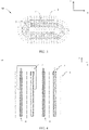
- FIG. 1 shows a secondary battery 5 of a rectangular structure.
- the secondary battery includes a lithium-ion battery, a lithium-sulfur battery, a sodium/lithium-ion battery, a sodium ion battery, a magnesium ion battery, or the like.
- the following mainly uses a lithium-ion battery as an example to describe the idea of this application. It should be understood that the idea is applicable to any other appropriate types of rechargeable batteries.
- a secondary battery 5 includes a shell (including a housing 51 and a cover plate 53) and an electrode assembly 52.
- the housing 51 may include a base plate and a side plate connected onto the base plate, where the base plate and the side plate enclose an accommodating cavity.
- This application does not impose any special limitations on the shape of the housing 51, and the housing may be cylindrical, rectangular, or of any other shapes.
- the housing 51 has an opening communicating with the accommodating cavity, and the cover plate 53 can cover the opening to seal the accommodating cavity.
- the electrode assembly 52 is packaged in the accommodating cavity. Electrolyte infiltrates into the electrode assembly 52. There may be one or more electrode assemblies 52 in the secondary battery 5, and persons skilled in the art may make choices according to actual requirements.
- the electrode assembly 52 is a core component of the secondary battery for implementing charge and discharge functions.
- the electrode assembly 52 includes a first electrode plate 6, a second electrode plate 7, and a separator 9, and the separator 9 separates the first electrode plate 6 from the second electrode plate 7.
- Working of the lithium-ion battery cell mainly relies on migration of lithium ions between the first electrode plate 6 and the second electrode plate 7 via the separator 9.
- the electrode assembly 52 may be a winding structure. Specifically, one first electrode plate 6 and one second electrode plate 7 are provided, and the first electrode plate 6 and the second electrode plate 7 are both strip structures. The first electrode plate 6, the separator 9, and the second electrode plate 7 are stacked sequentially and wound for two or more turns to form the electrode assembly 52.
- the electrode assembly 52 may be flat-shaped.
- the electrode assembly 52 may be a laminated structure.
- the first electrode plate 6 is provided in plurality and the second electrode plate 7 is provided in plurality.
- the plurality of first electrode plates 6 and the plurality of second electrode plates 7 are alternately stacked, with the separators 9 separating the first electrode plates 6 from the second electrode plates 7.
- Two electrode terminals 55 are provided which are disposed at the cover plate 53.
- Two connection members 54 are provided, one connection member 54 being connected to one electrode terminal 55 and the first electrode plate 6 of the electrode assembly 52, and the other connection member 54 being connected to the other electrode terminal 55 and the second electrode plate 7 of the electrode assembly 52.
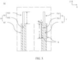
- the electrode assembly 52 includes a first electrode plate 6 and a second electrode plate 7, and a first tab 612 and a second tab 712 are located on one same side of the electrode assembly 52.
- the first electrode plate 6 includes a first current collector 61 and a first active material layer 62
- the first current collector 61 includes a first body portion 611 and a first tab 612
- the first active material layer 62 is applied on a surface of the first body portion 611
- the first tab 612 extends from an end of the first body portion 611 in a first direction (Z direction).
- the first electrode plate may be a positive electrode plate, and correspondingly, the first current collector 61 is made of aluminum foil, and the first active material layer 62 includes a ternary material, lithium manganate, or lithium iron phosphate.
- Aplurality of first tabs 612 may be provided, the plurality of first tabs 612 are stacked together and welded to a connection member 54.
- the second electrode plate 7 includes a second current collector 71 and a second active material layer 72, the second current collector 71 includes a second body portion 711 and a second tab 712, the second active material layer 72 is applied on a surface of the second body portion 711, and the second tab 712 extends from an end of the second body portion 711 in the first direction.
- the second electrode plate 7 may be a negative electrode plate, and correspondingly, the second current collector 71 is made of copper foil, and the second active material layer 72 includes graphite or silicon.
- a plurality of second tabs 712 may be provided. The plurality of second tabs 712 are stacked together and welded to the connection member 54.
- At least an end part of the second active material layer 72 close to the first tab 612 is coated with a ceramic coating 8 in a second direction (Y direction) perpendicular to the first direction (Z direction), where length of the ceramic coating 8 in the first direction is 1/3-3/2 of length of the first tab in the first direction, that is, 1/3 ⁇ y/x ⁇ 3/2. Moreover, the thickness (d1) of the ceramic coating is 2 ⁇ m to 20 ⁇ m.
- the ceramic coating 8 contains a ceramic material and a binder.
- the ceramic coating may use a ceramic coating slurry with a ratio of ceramic material, binder, dispersing agent, and defoaming agent being 39:2:12:5:0.2, which has a solid content of 30%-50%.
- the coating material may be one of alumina hydrate, magnesium oxide, silicon carbide, and silicon nitride, preferably, alumina hydrate.
- the binder may be selected from a combination of one or more of polyacrylate, methyl acrylate, ethyl acrylate, 2-methyl methacrylate, and 2-ethyl methacrylate.
- the thickener may be selected from one of sodium carboxy methyl cellulose, carboxy methyl cellulose, methyl cellulose, and polyacrylic acid sodium.
- the dispersing agent may be selected from a combination of one or more of polyvinyl alcohol, polyacrylamide, and polyvinylpyrrolidone.
- the defoaming agent may be selected from a combination of one or more of 1-butanol and ethanol.
- the first tab 612 and the second tab 712 are both provided in plurality.
- roots of the tabs are prone to be bent and in contact with the active material layer, causing a risk of internal short circuit.
- the separator 9 may contract during use of the battery to cause short circuit. The applicant has discovered that the battery is more likely to catch fire due to internal short circuit when the tab of its positive electrode (the first tab 612) is in contact with the active material layer of its negative electrode (the second active material layer 72), as compared with other circumstances.
- the ceramic coating 8 is provided on at least an end part of the second active material layer 72 close to the first tab 612.
- the bent first tab 612 is not in direct contact with the second active material layer 72, but is in contact with the insulating ceramic coating 8, avoiding internal short circuit occurring due to bending of the first tab 612 and its contact with the second active material layer 72, thereby improving safety of the battery.
- the ceramic coating is applied everywhere on the first active material layer 62 and the second active material layer 72.
- Such method although improving safety, causes notable loss of energy density of the battery.
- the inventors conclude a relationship between the length (x) of the first tab 612 and the length (y) of the ceramic coating 8 based on experiments, and the length (y) of the ceramic coating 8 and thickness (d1) of the ceramic coating 8 are limited so as to reduce the loss of energy density while the same safety effect is achieved.
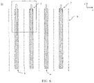
- FIG. 6 and FIG. 7 illustrate Embodiment 2.
- the first tab 612 and the second tab 712 are located the same side of the electrode assembly 52. Similarities of Embodiment 2 to Embodiment 1 are omitted, and only differences of Embodiment 2 from Embodiment 1 are described.
- the second active material layer 72 includes a substrate region 721 and a thinned region 722 extending from the substrate region, where thickness of the thinned region 722 is less than thickness of the substrate region 721.
- the thinned region 722 is provided on a side of the substrate region 721 close to the second tab 712.
- the thinned region 722 is provided with a ceramic coating 8.
- a difference between a sum of the thickness of the ceramic coating 8 and the thickness of the thinned region 722 and the thickness of the substrate region 721, for example, is less than 3 ⁇ m so that thickness of the ceramic coating 8 substantially makes up for the lost thickness of the thinned region.
- the sum of the thickness of the ceramic coating 8 and the thickness of the thinned region 722 is approximately equal to the thickness of the substrate region 721.
- the difference between the two may be controlled to be less than 3 ⁇ m, less than 1 ⁇ m, or the like.
- the thinned region 722 is provided on the second active material layer 72 at a position close to the second tab 712, so as to prevent stress concentration at a position in the end part of the active material layer close to the tab during cold pressing, where such stress concentration could result in break of the current collector.
- the thinned region 722 increases a gap between the first electrode plate 6 and the second electrode plate 7 so that electrolyte cannot fully fill this area under the action of capillarity, resulting in a risk of lithium precipitation in this area.
- the ceramic coating 8 adds to the thinned region 722, decreasing the gap between the first electrode plate 6 and the second electrode plate 7 and reducing the risk of breaking of the electrolyte bridge.
- ceramic powder has some electrolyte retention capacity due to its high porosity, further relieving lithium precipitation in the thinned region 722.
- the provision of the ceramic coating 8 on the thinned region 722 cannot only utilize the insulating property of ceramic to avoid internal short circuit occurring due to contact of the bent first tab with the second active material layer during assembling, but also utilize the porous nature of ceramic, that is, the electrolyte retention capacity of the ceramic coating, to ensure sufficient electrolyte in the thinned region, thereby relieving the problem of lithium precipitation in the thinned region.
- length (x) of the first tab 612 in the first direction, length (y) of the ceramic coating 8 in the first direction, thickness (d1) of the ceramic coating 8, and thickness (d2) of the thinned region 722 satisfy 0.09 ⁇ (0.283-d1/d2)/(y/x) ⁇ 0.25 and 0.07 ⁇ (0.23-d1/(d1+d2))/(y/x) ⁇ 0.20, optionally, 0.109 ⁇ (0.283-d1/d2)/(y/x) ⁇ 0.231 and 0.091 ⁇ (0.23-d1/(d1+d2))/(y/x) ⁇ 0.176.
- the ceramic coating 8 although able to provide insulation so as to prevent internal short circuit and able to retain electrolyte so as to relieve lithium precipitation at the edge, makes the volumetric energy density of the battery drop if having an excessively large length (y) or an excessively large thickness (d1).
- (0.283-d1/d2)/(y/x) may be within a numerical range with any two of the following values as end values: 0.090, 0.109, 0.119, 0.121, 0.129, 0.138, 0.143, 0.160, 0.163, 0.184, 0.202, 0.215, 0.226, 0.230, 0.231, and 0.250.
- (0.23-d1/(d1+d2))/(y/x) may be within a numerical range with any two of the following values as end values: 0.070, 0.091, 0.091, 0.096, 0.099, 0.104, 0.109, 0.120, 0.128, 0.138, 0.152, 0.163, 0.173, 0.174, 0.176, 0.199, and 0.200.
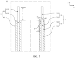
- FIG. 8 illustrates Embodiment 3. It can be seen from FIG. 8 that Embodiment 3 differs from Embodiment 1 and Embodiment 2 in that the first tab 612 and the second tab 712 are located on two sides of the electrode assembly 52 in the first direction (Z direction). Similarities of Embodiment 3 to Embodiment 1 and Embodiment 2 are omitted, and only differences of Embodiment 3 from Embodiment 1 are described.
- An end part of the first active material layer 62 close to the second tab 712 is coated with a ceramic coating 8 in the second direction (Y direction), where length of the ceramic coating 8 in the first direction is 1/3-3/2 of length of the second tab 712 in the first direction.
- the ceramic coating 8 that is applied on the second electrode plate 7 can prevent contact between the first tab 612 and the second active material layer 72, and the additional ceramic coating 8 provided on the end part of the first active material layer 62 close to the second tab 712 can further prevent contact between the second tab 7 and the first active material layer 62, thereby further improving safety of the battery.
- the electrode assembly in embodiment 3 may also have the thinned region 722 as in embodiment 2.
- FIG. 9 illustrates Embodiment 4.
- Embodiment 4 differs from Embodiment 2 in that the first tab 612 and the second tab 712 are located on two sides of the electrode assembly 52 in the first direction (Z direction).
- a thinned region of the second active material layer 72 is further provided on a side of the substrate region 721 close to the first tab 612.
- the thinned region is provided with a ceramic coating 8, and a difference between a sum of thickness of the ceramic coating 8 and thickness of the thinned region and thickness of the substrate region 721 is less than 3 ⁇ m.
- the second electrode plate 7 has two thinned regions 722a and 722b in embodiment 4.
- One thinned region 722a is close to the second tab 712, which is a thinned region provided for preventing stress concentration during cold pressing, and the provision of a ceramic coating 8 on this thinned region can relieve the problem of lithium precipitation in the thinned region 722a.
- the other thinned region 722b is provided close to the first tab 612, and the provision of a ceramic coating 8 on this thinned region 722b can avoid contact of the bent first tab 612 with the second active material layer 72 without affecting volumetric energy density of the battery. In this way, safety of the battery is improved.
- the secondary battery may be used to assemble a battery module, and the battery module may include one or more secondary batteries.
- the specific quantity may be chosen by persons skilled in the art based on use and capacity of the battery module.
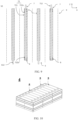
- FIG. 10 shows a battery module 4 as an example.
- a plurality of batteries 5 may be sequentially arranged along a length direction of the battery module 4.
- the secondary batteries may alternatively be arranged in any other manners.
- the plurality of secondary batteries 5 may be fastened by fasteners.
- the battery module 4 may further include a shell with an accommodating space, and the plurality of secondary batteries 5 are accommodated in the accommodating space.
- the battery module may be used to assemble a battery pack, and the quantity of battery modules included in the battery pack may be chosen by persons skilled in the art based on use and capacity of the battery pack.
- FIG. 11 and FIG. 12 show a battery pack 1 as an example.
- the battery pack 1 may include a battery box and a plurality of battery modules 4 arranged in the battery box.
- the battery box includes an upper box body 2 and a lower box body 3.
- the upper box body 2 can cover the lower box body 3 to form an enclosed space for accommodating the battery module 4.
- the plurality of battery modules 4 may be arranged in the battery box in any manner.
- the apparatus includes one or more of the secondary battery, the battery module, or the battery pack provided in this application.
- the secondary battery, the battery module, or the battery pack may be used as a power source for the apparatus, or an energy storage unit of the apparatus.
- the apparatus may be, but is not limited to, a mobile device (for example, a mobile phone or a notebook computer), an electric vehicle (for example, a battery electric vehicle, a hybrid electric vehicle, a plug-in hybrid electric vehicle, an electric bicycle, an electric scooter, an electric golf vehicle, or an electric truck), an electric train, a ship, a satellite, an energy storage system, and the like.
- a secondary battery, a battery module, or a battery pack may be selected according to requirements for using the apparatus.
- FIG. 13 shows an apparatus as an example.
- the apparatus is a battery electric vehicle, a hybrid electric vehicle, or a plug-in hybrid electric vehicle, or the like.
- a battery pack or a battery module may be used.
- the positive electrode plate, the separator, and the negative electrode plate of Embodiment 2 were sequentially stacked so that the separator was located between the positive electrode plate and the negative electrode plate to provide separation. Then, the resulting stack were wound to form an electrode assembly.
- the electrode assembly was placed in an outer package and the prepared electrolyte was injected, followed by processes including vacuum packaging, standing, formation, and shaping, to obtain a secondary battery.
- the ceramic material used was alumina hydrate
- the binder was polyacrylate
- the thickener was polyvinyl alcohol
- the defoaming agent was 1-butanol.
- Comparative Examples 1 to 6 were prepared in the same method as Examples 1 to 19, except that the proportional relation of length x of the first tab, length y of the ceramic coating, thickness d1 of the ceramic coating 8, and thickness d2 of the thinned region 722 was adjusted.
- the positive tab was bent to be in contact with the negative electrode active material so as to make a short circuit, and safety of the batteries was compared under this condition.
- the battery was subjected to a charge and discharge test and observation was made to check for any precipitation of lithium in the thinned region.
- volumetric energy density of a battery without any ceramic coating 8 was set as a reference value, that is, 100%, and relative volumetric energy densities of the examples and comparative examples were calculated with respect to the reference value.
- Example 1 Light smoke without fire Light precipitation of lithium 100% Example 2 No fire No 99.85%
- Example 3 No fire Light precipitation of lithium 99.97%
- Example 4 No fire No 99.95%
- Example 5 No fire No 99.93%
- Example 6 No fire No 100%
- Example 7 No fire No 100%
- Example 8 No fire No 99.95%
- Example 13 No fire No 99.94% Example 14 No fire No 99.95%
- Example 15 No fire No 99.97%
- Example 16 Light smoke without fire Light precipitation of lithium 100%
Landscapes
- Chemical & Material Sciences (AREA)
- Chemical Kinetics & Catalysis (AREA)
- Electrochemistry (AREA)
- General Chemical & Material Sciences (AREA)
- Engineering & Computer Science (AREA)
- Manufacturing & Machinery (AREA)
- Materials Engineering (AREA)
- Connection Of Batteries Or Terminals (AREA)
Applications Claiming Priority (2)
| Application Number | Priority Date | Filing Date | Title |
|---|---|---|---|
| CN202110704373.7A CN115528201A (zh) | 2021-06-24 | 2021-06-24 | 电极组件、电池、电池模块、电池包以及用电装置 |
| PCT/CN2022/086771 WO2022267639A1 (zh) | 2021-06-24 | 2022-04-14 | 电极组件、电池、电池模块、电池包以及用电装置 |
Publications (2)
| Publication Number | Publication Date |
|---|---|
| EP4152437A1 true EP4152437A1 (de) | 2023-03-22 |
| EP4152437A4 EP4152437A4 (de) | 2024-08-07 |
Family
ID=84545207
Family Applications (1)
| Application Number | Title | Priority Date | Filing Date |
|---|---|---|---|
| EP22818590.6A Pending EP4152437A4 (de) | 2021-06-24 | 2022-04-14 | Elektrodenanordnung, batterie, batteriemodul, batteriepack und elektrische vorrichtung |
Country Status (4)
| Country | Link |
|---|---|
| US (1) | US20230216062A1 (de) |
| EP (1) | EP4152437A4 (de) |
| CN (1) | CN115528201A (de) |
| WO (1) | WO2022267639A1 (de) |
Cited By (1)
| Publication number | Priority date | Publication date | Assignee | Title |
|---|---|---|---|---|
| EP4510356A4 (de) * | 2022-10-21 | 2025-09-17 | Contemporary Amperex Technology Hong Kong Ltd | Batteriezelle, batterie und elektrische vorrichtung |
Families Citing this family (3)
| Publication number | Priority date | Publication date | Assignee | Title |
|---|---|---|---|---|
| CN115911512A (zh) * | 2022-12-30 | 2023-04-04 | 惠州亿纬锂能股份有限公司 | 一种锂离子电池 |
| CN116435726A (zh) * | 2023-06-15 | 2023-07-14 | 深圳海辰储能控制技术有限公司 | 电极组件、圆柱电池及用电设备 |
| CN116581243B (zh) * | 2023-07-12 | 2023-11-21 | 宁德时代新能源科技股份有限公司 | 电极极片、其制备方法、二次电池和用电装置 |
Family Cites Families (12)
| Publication number | Priority date | Publication date | Assignee | Title |
|---|---|---|---|---|
| JP4031635B2 (ja) * | 2001-11-08 | 2008-01-09 | Tdk株式会社 | 電気化学デバイス |
| CN201345383Y (zh) * | 2008-08-26 | 2009-11-11 | 比亚迪股份有限公司 | 一种锂离子二次电池 |
| JP5858325B2 (ja) * | 2010-09-03 | 2016-02-10 | 株式会社Gsユアサ | 電池 |
| KR101586530B1 (ko) * | 2013-03-11 | 2016-01-21 | 주식회사 엘지화학 | 양극 탭 상에 절연층을 포함하는 양극 및 이를 포함하는 이차 전지 |
| US20170005318A1 (en) * | 2014-03-25 | 2017-01-05 | Nec Corporation | Laminated-type battery and method for manufacturing the same |
| KR102177506B1 (ko) * | 2014-07-30 | 2020-11-11 | 삼성에스디아이 주식회사 | 이차 전지 및 그 제조 방법 |
| CN206250284U (zh) * | 2016-12-02 | 2017-06-13 | 东莞新能源科技有限公司 | 一种阳极极片及其电芯 |
| JP2019153434A (ja) * | 2018-03-01 | 2019-09-12 | 株式会社東芝 | 積層体及び二次電池 |
| CN111326699B (zh) * | 2019-08-14 | 2021-11-09 | 宁德时代新能源科技股份有限公司 | 二次电池 |
| CN118738408A (zh) * | 2019-08-14 | 2024-10-01 | 宁德时代新能源科技股份有限公司 | 电极组件和二次电池 |
| CN211605277U (zh) * | 2020-01-06 | 2020-09-29 | 万向一二三股份公司 | 一种防止极耳折断的陶瓷涂层极片 |
| CN112397685B (zh) * | 2020-11-16 | 2022-02-15 | 珠海冠宇电池股份有限公司 | 一种负极片及其应用 |
-
2021
- 2021-06-24 CN CN202110704373.7A patent/CN115528201A/zh active Pending
-
2022
- 2022-04-14 EP EP22818590.6A patent/EP4152437A4/de active Pending
- 2022-04-14 WO PCT/CN2022/086771 patent/WO2022267639A1/zh not_active Ceased
-
2023
- 2023-03-10 US US18/181,830 patent/US20230216062A1/en active Pending
Cited By (1)
| Publication number | Priority date | Publication date | Assignee | Title |
|---|---|---|---|---|
| EP4510356A4 (de) * | 2022-10-21 | 2025-09-17 | Contemporary Amperex Technology Hong Kong Ltd | Batteriezelle, batterie und elektrische vorrichtung |
Also Published As
| Publication number | Publication date |
|---|---|
| US20230216062A1 (en) | 2023-07-06 |
| EP4152437A4 (de) | 2024-08-07 |
| WO2022267639A1 (zh) | 2022-12-29 |
| CN115528201A (zh) | 2022-12-27 |
Similar Documents
| Publication | Publication Date | Title |
|---|---|---|
| EP4152437A1 (de) | Elektrodenanordnung, batterie, batteriemodul, batteriepack und elektrische vorrichtung | |
| US12500242B2 (en) | Electrode assembly and battery cell | |
| US20250015426A1 (en) | Housing, battery cell, battery, and power consuming device | |
| EP3852165A1 (de) | Stromabnahmeelement, sekundärbatterie und herstellungsverfahren für sekundärbatterie | |
| CN218867146U (zh) | 电极组件、电池单体、电池及用电装置 | |
| EP2602845B1 (de) | Sekundärbatterie beinhaltend elektrodenleitungen, die mit einer korrosionsschutzschicht beschichtet sind | |
| CN218275003U (zh) | 电极组件、电池单体、电池及用电装置 | |
| WO2024016452A1 (zh) | 隔膜、电池单体、热压模具、电池和用电装置 | |
| EP4471975A1 (de) | Sekundärbatterie mit nichtwässrigem elektrolyten | |
| WO2025103119A1 (zh) | 负极片、电池、电池包及用电设备 | |
| US11387495B2 (en) | Non-aqueous electrolyte secondary battery | |
| CN116982211A (zh) | 电池单体及其制造方法和制造设备、电池及用电装置 | |
| CN120149659B (zh) | 电池和用电装置 | |
| WO2024016447A1 (zh) | 集流体、极片、电池单体、热压模具、电池和用电装置 | |
| WO2024082271A1 (zh) | 电极组件、电池单体、电池及用电装置 | |
| US20240266616A1 (en) | Electrode plate and manufacturing method thereof, electrode assembly and manufacturing method thereof, battery cell, and battery | |
| CN221447208U (zh) | 极片、电极组件、电池单体、电池和用电装置 | |
| CN217588983U (zh) | 一种中间出极耳式正极片、电芯及电池 | |
| EP4376125A1 (de) | Positivelektrodenaktivmaterial, positivelektrodenfolie, elektrodenanordnung, batteriezelle, batterie und elektrische vorrichtung | |
| EP4156367A1 (de) | Batterie und elektronische vorrichtung | |
| WO2024066624A1 (zh) | 一种负极极片及其制备方法、电极组件、电池单体、电池和用电装置 | |
| CN212967762U (zh) | 一种卷绕式电芯 | |
| CN120127293B (zh) | 电池和用电装置 | |
| CN120127281B (zh) | 电池和用电装置 | |
| CN222637425U (zh) | 一种锂离子电芯和锂离子电池 |
Legal Events
| Date | Code | Title | Description |
|---|---|---|---|
| STAA | Information on the status of an ep patent application or granted ep patent |
Free format text: STATUS: UNKNOWN |
|
| STAA | Information on the status of an ep patent application or granted ep patent |
Free format text: STATUS: THE INTERNATIONAL PUBLICATION HAS BEEN MADE |
|
| PUAI | Public reference made under article 153(3) epc to a published international application that has entered the european phase |
Free format text: ORIGINAL CODE: 0009012 |
|
| STAA | Information on the status of an ep patent application or granted ep patent |
Free format text: STATUS: REQUEST FOR EXAMINATION WAS MADE |
|
| 17P | Request for examination filed |
Effective date: 20221216 |
|
| AK | Designated contracting states |
Kind code of ref document: A1 Designated state(s): AL AT BE BG CH CY CZ DE DK EE ES FI FR GB GR HR HU IE IS IT LI LT LU LV MC MK MT NL NO PL PT RO RS SE SI SK SM TR |
|
| A4 | Supplementary search report drawn up and despatched |
Effective date: 20240708 |
|
| RIC1 | Information provided on ipc code assigned before grant |
Ipc: H01M 50/591 20210101ALI20240702BHEP Ipc: H01M 50/586 20210101ALI20240702BHEP Ipc: H01M 50/55 20210101ALI20240702BHEP Ipc: H01M 50/548 20210101ALI20240702BHEP Ipc: H01M 4/62 20060101ALI20240702BHEP Ipc: H01M 10/0525 20100101ALI20240702BHEP Ipc: H01M 4/13 20100101AFI20240702BHEP |
|
| DAV | Request for validation of the european patent (deleted) | ||
| DAX | Request for extension of the european patent (deleted) | ||
| RAP1 | Party data changed (applicant data changed or rights of an application transferred) |
Owner name: CONTEMPORARY AMPEREX TECHNOLOGY(HONG KONG) LIMITED |
|
| STAA | Information on the status of an ep patent application or granted ep patent |
Free format text: STATUS: EXAMINATION IS IN PROGRESS |