EP4152311A1 - Musical sound signal generation device, musical sound signal generation method, and program - Google Patents
Musical sound signal generation device, musical sound signal generation method, and program Download PDFInfo
- Publication number
- EP4152311A1 EP4152311A1 EP22195619.6A EP22195619A EP4152311A1 EP 4152311 A1 EP4152311 A1 EP 4152311A1 EP 22195619 A EP22195619 A EP 22195619A EP 4152311 A1 EP4152311 A1 EP 4152311A1
- Authority
- EP
- European Patent Office
- Prior art keywords
- delay
- delay unit
- fractional
- unit
- value
- Prior art date
- Legal status (The legal status is an assumption and is not a legal conclusion. Google has not performed a legal analysis and makes no representation as to the accuracy of the status listed.)
- Granted
Links
Images





Classifications
-
- G—PHYSICS
- G10—MUSICAL INSTRUMENTS; ACOUSTICS
- G10H—ELECTROPHONIC MUSICAL INSTRUMENTS; INSTRUMENTS IN WHICH THE TONES ARE GENERATED BY ELECTROMECHANICAL MEANS OR ELECTRONIC GENERATORS, OR IN WHICH THE TONES ARE SYNTHESISED FROM A DATA STORE
- G10H7/00—Instruments in which the tones are synthesised from a data store, e.g. computer organs
- G10H7/008—Means for controlling the transition from one tone waveform to another
-
- G—PHYSICS
- G10—MUSICAL INSTRUMENTS; ACOUSTICS
- G10H—ELECTROPHONIC MUSICAL INSTRUMENTS; INSTRUMENTS IN WHICH THE TONES ARE GENERATED BY ELECTROMECHANICAL MEANS OR ELECTRONIC GENERATORS, OR IN WHICH THE TONES ARE SYNTHESISED FROM A DATA STORE
- G10H1/00—Details of electrophonic musical instruments
- G10H1/02—Means for controlling the tone frequencies, e.g. attack or decay; Means for producing special musical effects, e.g. vibratos or glissandos
- G10H1/04—Means for controlling the tone frequencies, e.g. attack or decay; Means for producing special musical effects, e.g. vibratos or glissandos by additional modulation
- G10H1/053—Means for controlling the tone frequencies, e.g. attack or decay; Means for producing special musical effects, e.g. vibratos or glissandos by additional modulation during execution only
- G10H1/057—Means for controlling the tone frequencies, e.g. attack or decay; Means for producing special musical effects, e.g. vibratos or glissandos by additional modulation during execution only by envelope-forming circuits
-
- G—PHYSICS
- G10—MUSICAL INSTRUMENTS; ACOUSTICS
- G10H—ELECTROPHONIC MUSICAL INSTRUMENTS; INSTRUMENTS IN WHICH THE TONES ARE GENERATED BY ELECTROMECHANICAL MEANS OR ELECTRONIC GENERATORS, OR IN WHICH THE TONES ARE SYNTHESISED FROM A DATA STORE
- G10H1/00—Details of electrophonic musical instruments
- G10H1/02—Means for controlling the tone frequencies, e.g. attack or decay; Means for producing special musical effects, e.g. vibratos or glissandos
- G10H1/06—Circuits for establishing the harmonic content of tones, or other arrangements for changing the tone colour
- G10H1/12—Circuits for establishing the harmonic content of tones, or other arrangements for changing the tone colour by filtering complex waveforms
- G10H1/125—Circuits for establishing the harmonic content of tones, or other arrangements for changing the tone colour by filtering complex waveforms using a digital filter
-
- G—PHYSICS
- G10—MUSICAL INSTRUMENTS; ACOUSTICS
- G10H—ELECTROPHONIC MUSICAL INSTRUMENTS; INSTRUMENTS IN WHICH THE TONES ARE GENERATED BY ELECTROMECHANICAL MEANS OR ELECTRONIC GENERATORS, OR IN WHICH THE TONES ARE SYNTHESISED FROM A DATA STORE
- G10H2210/00—Aspects or methods of musical processing having intrinsic musical character, i.e. involving musical theory or musical parameters or relying on musical knowledge, as applied in electrophonic musical tools or instruments
- G10H2210/155—Musical effects
- G10H2210/195—Modulation effects, i.e. smooth non-discontinuous variations over a time interval, e.g. within a note, melody or musical transition, of any sound parameter, e.g. amplitude, pitch, spectral response or playback speed
- G10H2210/221—Glissando, i.e. pitch smoothly sliding from one note to another, e.g. gliss, glide, slide, bend, smear or sweep
- G10H2210/225—Portamento, i.e. smooth continuously variable pitch-bend, without emphasis of each chromatic pitch during the pitch change, which only stops at the end of the pitch shift, as obtained, e.g. by a MIDI pitch wheel or trombone
-
- G—PHYSICS
- G10—MUSICAL INSTRUMENTS; ACOUSTICS
- G10H—ELECTROPHONIC MUSICAL INSTRUMENTS; INSTRUMENTS IN WHICH THE TONES ARE GENERATED BY ELECTROMECHANICAL MEANS OR ELECTRONIC GENERATORS, OR IN WHICH THE TONES ARE SYNTHESISED FROM A DATA STORE
- G10H2210/00—Aspects or methods of musical processing having intrinsic musical character, i.e. involving musical theory or musical parameters or relying on musical knowledge, as applied in electrophonic musical tools or instruments
- G10H2210/155—Musical effects
- G10H2210/265—Acoustic effect simulation, i.e. volume, spatial, resonance or reverberation effects added to a musical sound, usually by appropriate filtering or delays
-
- G—PHYSICS
- G10—MUSICAL INSTRUMENTS; ACOUSTICS
- G10H—ELECTROPHONIC MUSICAL INSTRUMENTS; INSTRUMENTS IN WHICH THE TONES ARE GENERATED BY ELECTROMECHANICAL MEANS OR ELECTRONIC GENERATORS, OR IN WHICH THE TONES ARE SYNTHESISED FROM A DATA STORE
- G10H2250/00—Aspects of algorithms or signal processing methods without intrinsic musical character, yet specifically adapted for or used in electrophonic musical processing
- G10H2250/025—Envelope processing of music signals in, e.g. time domain, transform domain or cepstrum domain
-
- G—PHYSICS
- G10—MUSICAL INSTRUMENTS; ACOUSTICS
- G10H—ELECTROPHONIC MUSICAL INSTRUMENTS; INSTRUMENTS IN WHICH THE TONES ARE GENERATED BY ELECTROMECHANICAL MEANS OR ELECTRONIC GENERATORS, OR IN WHICH THE TONES ARE SYNTHESISED FROM A DATA STORE
- G10H2250/00—Aspects of algorithms or signal processing methods without intrinsic musical character, yet specifically adapted for or used in electrophonic musical processing
- G10H2250/041—Delay lines applied to musical processing
- G10H2250/046—Delay lines applied to musical processing with intermediate taps
-
- G—PHYSICS
- G10—MUSICAL INSTRUMENTS; ACOUSTICS
- G10H—ELECTROPHONIC MUSICAL INSTRUMENTS; INSTRUMENTS IN WHICH THE TONES ARE GENERATED BY ELECTROMECHANICAL MEANS OR ELECTRONIC GENERATORS, OR IN WHICH THE TONES ARE SYNTHESISED FROM A DATA STORE
- G10H2250/00—Aspects of algorithms or signal processing methods without intrinsic musical character, yet specifically adapted for or used in electrophonic musical processing
- G10H2250/041—Delay lines applied to musical processing
- G10H2250/051—Delay lines applied to musical processing with variable time delay or variable length
-
- G—PHYSICS
- G10—MUSICAL INSTRUMENTS; ACOUSTICS
- G10H—ELECTROPHONIC MUSICAL INSTRUMENTS; INSTRUMENTS IN WHICH THE TONES ARE GENERATED BY ELECTROMECHANICAL MEANS OR ELECTRONIC GENERATORS, OR IN WHICH THE TONES ARE SYNTHESISED FROM A DATA STORE
- G10H2250/00—Aspects of algorithms or signal processing methods without intrinsic musical character, yet specifically adapted for or used in electrophonic musical processing
- G10H2250/055—Filters for musical processing or musical effects; Filter responses, filter architecture, filter coefficients or control parameters therefor
- G10H2250/061—Allpass filters
-
- G—PHYSICS
- G10—MUSICAL INSTRUMENTS; ACOUSTICS
- G10H—ELECTROPHONIC MUSICAL INSTRUMENTS; INSTRUMENTS IN WHICH THE TONES ARE GENERATED BY ELECTROMECHANICAL MEANS OR ELECTRONIC GENERATORS, OR IN WHICH THE TONES ARE SYNTHESISED FROM A DATA STORE
- G10H2250/00—Aspects of algorithms or signal processing methods without intrinsic musical character, yet specifically adapted for or used in electrophonic musical processing
- G10H2250/055—Filters for musical processing or musical effects; Filter responses, filter architecture, filter coefficients or control parameters therefor
- G10H2250/101—Filter coefficient update; Adaptive filters, i.e. with filter coefficient calculation in real time
-
- G—PHYSICS
- G10—MUSICAL INSTRUMENTS; ACOUSTICS
- G10H—ELECTROPHONIC MUSICAL INSTRUMENTS; INSTRUMENTS IN WHICH THE TONES ARE GENERATED BY ELECTROMECHANICAL MEANS OR ELECTRONIC GENERATORS, OR IN WHICH THE TONES ARE SYNTHESISED FROM A DATA STORE
- G10H2250/00—Aspects of algorithms or signal processing methods without intrinsic musical character, yet specifically adapted for or used in electrophonic musical processing
- G10H2250/471—General musical sound synthesis principles, i.e. sound category-independent synthesis methods
- G10H2250/511—Physical modelling or real-time simulation of the acoustomechanical behaviour of acoustic musical instruments using, e.g. waveguides or looped delay lines
- G10H2250/535—Waveguide or transmission line-based models
-
- G—PHYSICS
- G10—MUSICAL INSTRUMENTS; ACOUSTICS
- G10H—ELECTROPHONIC MUSICAL INSTRUMENTS; INSTRUMENTS IN WHICH THE TONES ARE GENERATED BY ELECTROMECHANICAL MEANS OR ELECTRONIC GENERATORS, OR IN WHICH THE TONES ARE SYNTHESISED FROM A DATA STORE
- G10H2250/00—Aspects of algorithms or signal processing methods without intrinsic musical character, yet specifically adapted for or used in electrophonic musical processing
- G10H2250/541—Details of musical waveform synthesis, i.e. audio waveshape processing from individual wavetable samples, independently of their origin or of the sound they represent
- G10H2250/621—Waveform interpolation
Definitions
- the present disclosure relates to a musical sound signal generation device, a musical sound signal generation method, and a program.
- the number of delay units constituting a wave guide modeling sound source is an integer and is discrete. Therefore, a technique for achieving a delay length of a fraction finer than the integer corresponding to the number of delay units is required in order to determine a strict frequency.
- JP H6-348277 A As a related art for continuously achieving fractional delay lengths in a wide frequency band, for example, there is known a technique of inserting an all-pass filter before a final stage of a delay unit in JP H6-348277 A .
- This technique achieves a musical sound signal synthesis device including: a first all-pass filter APF1; a second all-pass filter APF2; a variable connection means for connecting the first and second all-pass filters to selected different stages of delay elements; a control means for controlling the all-pass filters and the variable connection means such that delay times become equal in outputs of the first and second all-pass filters; and a weighted addition means for performing weighted addition of the outputs of the first and second all-pass filters.
- a fractional delay length is generated by the weighted addition of the two all-pass filters to suppress generation of noise due to discontinuous transition of a coefficient of the all-pass filter between 0.0 and 1.0 when a tone pitch frequency changes with time and an integer delay length in a wave guide modeling sound source is switched with a lapse of time, such as at the time of pitch bend.
- one advantage of the present disclosure is to generate a musical sound with a small amount of calculation.
- a musical sound signal generation device continuously connects any one of a connected zeroth delay unit and a connected second delay unit to a fractional delay block and connects at least any one of a new zeroth delay unit and a new second delay unit to at least any one of the fractional delay block other than the fractional delay block connected to a new first delay unit in response to setting any one of the connected zeroth delay unit and the connected second delay unit as the new first delay unit, setting a delay unit in a preceding stage of the new first delay unit as the new zeroth delay unit, and setting a delay unit in a subsequent stage of the new first delay unit as the new second delay unit in accordance with a change in a designated tone pitch.
- An electronic device includes a musical sound signal generation device 100, a performance operator (not illustrated), and a speaker.
- the performance operator corresponds to a key when the electronic device is a keyboard, such as an electronic piano, and corresponds to a mouthpiece when the electronic device is an electronic wind instrument.
- Fig. 1 is a block diagram illustrating exemplary hardware of an embodiment of the musical sound signal generation device 100 according to the present disclosure.
- the musical sound signal generation device 100 includes: at least one central processing unit (CPU) 101 as a processor; a read only memory (ROM) 102; a random access memory (RAM) 103; a digital signal processor (DSP) or a wave guide model circuit 104; a pitch bend sensor 110 and an analog-todigital converter (ADC) 106 to which an output of the pitch bend sensor 110 is connected; a volume sensor 109 and an ADC or a digital input port 105 configured to detect the volume sensor 109; a tone pitch designation switch 111 and a digital input port 107 to which an output of the tone pitch designation switch is connected; a digitalto-analog converter (DAC)/amplifier 108; and a system bus 112.
- CPU central processing unit
- ROM read only memory
- RAM random access memory
- DSP digital signal processor
- ADC analog-todigital converter
- the CPU 101, the ROM 102, the RAM 103, the DSP or wave guide model circuit 104, the ADC 106, the ADC or digital input port 105, the digital input port 107, and the DAC/amplifier 108 are connected to each other by the system bus 112.
- the volume sensor 109 and the tone pitch designation switch 111 may be the same.
- a switch sensing that a key has been pushed serves as both a tone pitch sensor and a volume sensor.
- FIG. 2 is a block diagram illustrating exemplary functions implemented by the DSP or wave guide model circuit 104.
- a wave guide model control unit 201 which is a control circuit, receives tone pitch information 203 (for example, a note number depending on a key in the case of the electronic piano) input from the tone pitch designation switch 111 in Fig. 1 and bend information (pitch change amount) 204 transmitted from the pitch bend sensor 110 in Fig.
- tone pitch information 203 for example, a note number depending on a key in the case of the electronic piano
- bend information (pitch change amount) 204 transmitted from the pitch bend sensor 110 in Fig.
- the wave guide model control unit 201 calculates a volume 207 of an excitation original sound 206 on the basis of volume information 205 input from the volume sensor 109 in Fig. 1 . Then, the excitation original sound 206 is multiplied by the volume 207 by a multiplier 208.
- the excitation original sound 206 is a signal that serves as a source of resonance in wave guide modeling and is a signal that is recorded in advance and stored in, for example, the ROM 102 in Fig. 1 , is copied from the ROM 102 to the RAM 103 in response to an activation of a system, and is read from the RAM 103 in response to a start of sound generation control, or is a signal synthesized by calculation.
- the wave guide model calculation unit 202 receives the excitation original sound 206 multiplied by the volume 207 as an input signal x(n) and the delay length (the number of delay units k and the filter coefficient g), performs calculation to be described later with reference to Fig. 3 , and outputs a musical sound signal 209.
- the musical sound signal 209 is input to the DAC/amplifier 108 in Fig. 1 and emitted via a speaker or the like of an electronic device (electronic musical instrument).
- Fig. 3 is a diagram illustrating an exemplary block configuration of the wave guide model calculation unit 202 in Fig. 2 .
- a delay line 301 includes N (a plurality of) delay units 302 including #0 to #N-1 connected in a cascade manner (in series).
- the delay unit 302 delays an input signal by one sampling time and outputs the delayed signal.
- a symbol z-1 in each of the delay units 302 in Fig. 3 indicates that a delay operation for one sample in z-conversion is executed.
- a signal obtained by adding, by an adder 311, a signal obtained by multiplying the input signal x(n) see Fig.
- the wave guide model calculation unit 202 includes three all-pass filter circuits (hereinafter referred to as "APF") 305 including #0, #1, and #2.
- the APF 305 is connected to both ends of any of the delay units 302 in the delay line 301, thereby operating as the all-pass filter.
- the APF 305 includes: a multiplier 306 that multiplies a signal on an input side of the connected delay unit 302 by a feedforward gain g (g0, g1, or g2); an adder 309 that adds a signal on an output side of the connected delay unit 302, an output signal of the multiplier 306, and an output signal of a multiplier 308 to be described later and selectively outputs the added output signal to a switch 310; a feedback delay unit 307 that delays the added output signal by one sampling time; and the multiplier 308 that multiplies an output signal of the feedback delay unit 307 by a feedback gain -g (-g0, -g1, or -g2) and outputs the multiplied output signal to the adder 309.
- a multiplier 306 that multiplies a signal on an input side of the connected delay unit 302 by a feedforward gain g (g0, g1, or g2)
- an adder 309 that adds a signal on an output side of the connected delay
- connection terminals i00 and i01 of the APF 305(#0), connection terminals i10 and i11 of the APF 305(#1), and connection terminals i20 and i21 of the APF 305(#2) is connected to delay line switch terminals at both ends of the same delay unit 302 of the delay line 301.
- the APF 305(#0), the APF 305(#1), and the APF 305(#2) respectively include sets of the feedforward gain and the feedback gain, that is, (g0 and -g0), (g1 and -g1), and (g2 and -g2).
- the feedforward gain and the feedback gain are collectively referred to as a filter coefficient of the all-pass filter.
- the APF 305(#0), the APF 305(#1), and the APF 305(#2) are always connected to the respective adjacent delay units 302 in the delay line 301, and the order thereof is controlled to be switched in the order of an annular ring by pitch bend control processing to be described later.
- Each output destination of the APF 305(#0), the APF 305(#1), or the APF 305(#2) is connected to each output selection terminal o0, o1, or o2 of the switch 310, and one of the output selection terminals is selected to output an output signal y(n), whereby the musical sound signal 209 is output.
- the output signal y(n) is multiplied by an output feedback gain by the multiplier 304, and the multiplication result is added to the input signal x(n) by the adder 311.
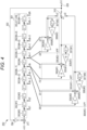
- Fig. 4 is a diagram illustrating exemplary connections of the three sets of APFs 305 including #0, #1, and #2 to the delay line 301 in the wave guide model calculation unit 202 in Fig. 2 having the configuration of Fig. 3 .
- the wave guide model control unit 201 in Fig. 2 calculates the delay length of the wave guide model corresponding to the frequency f at which a sound needs to be generated on the basis of the tone pitch information 203 input from the tone pitch designation switch 111 in Fig. 1 , which is the performance operator of the electronic musical instrument, for example, and then, designates the number of delay units k, which is the integer part of the delay length, to the wave guide model calculation unit 202.
- the wave guide model control unit 201 in Fig. 2 calculates the filter coefficient g of the APF 305 that defines the fractional part 1 of the delay length by calculation represented by Formula (1) described above, and designates the filter coefficient g to the wave guide model calculation unit 202.
- delay line switch terminals dk and dk+1 at both ends of a delay unit 302(#k) in the delay line 301 which is a first delay unit that generates a delay of the integer part of the delay length corresponding to a designated tone pitch designated by the wave guide model control unit 201, are respectively connected to the connection terminals i10 and i11 of the APF 305(#1).
- delay line switch terminals dk-1 and dk at both ends of a delay unit 302(#k-1), which is a zeroth delay unit in an immediately preceding stage of the delay unit 302(#k), which is the first delay unit, in the delay line 301 are respectively connected to the connection terminals i00 and i01 of the APF 305(#0).
- delay line switch terminals dk+1 and dk+2 at both ends of a delay unit 302(#k+1), which is a second delay unit in an immediately subsequent stage of the delay unit 302(#k), which is the first delay unit, in the delay line 301 are respectively connected to the connection terminals i20 and i21 of the APF 305(#2).
- the wave guide model control unit 201 in Fig. 2 sets the feedforward gain g and the feedback gain -g of the filter coefficient g, calculated by the calculation represented by Formula (1) to correspond to the fractional part 1 of the delay length corresponding to the designated tone pitch, respectively in the multipliers 306(#1) and 308(#1) of the APF 305(#1).
- a value of 0 that causes a delay of a value of 1 in the fractional part is set as the feedforward gain and the feedback gain of the filter coefficient in both of the multipliers 306(#0) and 308(#0) of the APF 305(#0).
- values of 1 and -1 that cause a delay of a value of 0 of the fractional part are respectively set as the feedforward gain and the feedback gain of the filter coefficient in the multipliers 306(#2) and 308(#2) of the APF 305(#2).
- the switch 310 causes conduction of the output selection terminal o1.
- an output signal of the APF 305(#1) is selected as the output signal y(n) via the switch 310, whereby the musical sound signal 209 is output.
- the output signal y(n) is multiplied by the output feedback gain by the multiplier 304, and the result is added to the input signal x(n) by the adder 311.
- the integer part k of the delay length corresponding to the designated tone pitch is generated by the delay units 302 including #0 to #k-1 in the delay line 301, and the fractional part 1 of the delay length is generated by the APF 305(#1) that operates on the basis of the filter coefficient g calculated by the calculation represented by Formula (1).
- a circuit including the delay line 301 and the APF 305(#1) has flat frequency characteristics, and thus, it is possible to prevent a decrease in amplitude in a high frequency band.
- Fig. 5 is an explanatory diagram of an effect of reducing a calculation load in the embodiment.
- the value of 0 that causes the delay of the value of 1 in the fractional part is set as the feedforward gain and the feedback gain of the filter coefficient in both of the multipliers 306(#0) and 308(#0) of the APF 305(#0). Therefore, it is substantially unnecessary for the multipliers 306(#0) and 308(#0) to execute a multiplication operation with a large load, and the APF 305(#0) in Fig. 4 is an equivalent circuit illustrated in Fig. 5 .
- the APF 305(#0) executes an operation of outputting an output from the delay unit 302(#k-1) in the delay line 301 via the delay line switch terminal dk directly to the output selection terminal o0 of the switch 310.
- the value of 1 and the value of -1 that cause the delay of the value of 0 of the fractional part are respectively set as the feedforward gain and the feedback gain of the filter coefficient in the multipliers 306(#2) and 308(#2) of the APF 305(#2) as described above. Therefore, it is substantially unnecessary for the multipliers 306(#2) and 308(#2) to execute a multiplication operation with a large load, and the APF 305(#2) in Fig. 4 is an equivalent circuit illustrated in Fig. 5 .
- the APF 305(#2) executes an operation of inputting an output from the delay unit 302(#k) in the delay line 301 via the delay line switch terminal dk+1 directly to the adder 309(#2), changing a sign of an output of the feedback delay unit 307(#2) by the multiplier 308(#2), and inputting the output with the changed sign to the adder 309(#2).
- the multiplication operation is substantially necessary only in the APF 305(#1) in the present embodiment, and the multiplication operation is unnecessary in the APF 305(#0) and the APF 305(#2). Therefore, the calculation load can be greatly reduced particularly in musical sound generation by the wave guide modeling with a large number of polyphonic sounds as compared with a technique of JP H6-348277 A in which two all-pass filters are used,.
- the wave guide model control unit 201 sequentially calculates a delay length of a new designated tone pitch on the basis of the sequentially input bend information 204, and sequentially outputs the number of delay units k, which is an integer part of the delay length, and the filter coefficient g, calculated by the calculation represented by Formula (1) corresponding to the fractional part 1, to the wave guide model calculation unit 202.
- a value of the number of delay units k does not change, only the filter coefficient g changes. This means that a change in wavelength of the musical sound signal 209 settles within one sampling time. For example, in a case where the player performs a pitch bend operation to decrease a pitch so that the fractional part 1 of a delay length corresponding to a new designated tone pitch sequentially increases, a value of the filter coefficient g calculated by the calculation represented by Formula (1) described above is designated to be sequentially decreased.
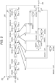
- Fig. 6 is a diagram illustrating a change in the connections of the three sets of APFs 305 to the delay line 301 when the number of delay units k, which is the integer part of the delay length, increases.
- the wave guide model control unit 201 in Fig. 2 increments a value of the number of delay units k, which is the integer part of the delay length of the designated tone pitch to be output to the wave guide model calculation unit 202, by +1.
- the fractional part 1 of the delay length becomes 0 due to the increment of the number of delay units k, the value of the filter coefficient g calculated by the calculation represented by Formula (1) becomes 1.
- the switch 310 cuts off the conduction of the output selection terminal o1 and newly causes conduction of the output selection terminal o2.
- the value of 1 and the value of -1 that cause the delay of the value of 0 of the fractional part are respectively set as the feedforward gain and the feedback gain of the filter coefficient in the multipliers 306(#2) and 308(#2) of the APF 305(#2) for the operation as described above. Therefore, the above-described operation of switching the operation of the all-pass filter from the APF 305(#1) to the APF 305(#2) matches well with the operation of controlling the fractional part 1 designated by the wave guide model control unit 201 in Fig. 2 to 0.
- the APF 305(#2) continuously operates according to actual signals from the delay line switch terminals dk+1 and dk+2, and thus, it is possible to perform control so as not to generate noise at the time of switching the APF 305.
- the value of the filter coefficient g calculated by the calculation represented by Formula (1) decreases toward 0 as described above.
- the operation is started with the value of the fractional part 1 being reset to 0, and thus, it is necessary to cause a jump of the value of the filter coefficient g from the vicinity of 0 to the vicinity of 1 at this moment.
- Such a discontinuous jump of the value is not so preferable when envelope control is performed on the filter coefficient g.
- the filter coefficient g is calculated by the calculation processing represented by Formula (1) described above.
- coefficients (1-g) and -(1-g) calculated using the coefficient g calculated by the calculation represented by the above Formula (2) are respectively set as a feedforward gain and a feedback gain in the multipliers 306 and 308.
- control may be performed such that (1-g) and -(1-g) are set as the feedforward gain and the feedback gain in the multipliers 306(#2) and 308(#2), respectively, when the operation of the all-pass filter is switched from the APF 305(#1) to the APF 305(#2) as described above.
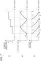
- Fig. 7 is an explanatory view of a method of continuously controlling the filter coefficient g.
- the filter coefficient g decreases with an increase of a fraction of a delay length as illustrated in Fig. 7(b) by the calculation represented by Formula (1) in a section l1 in which a value of the number of delay units, which is an integer part of the delay length, is k as illustrated in Fig. 7(a) .
- a value of the filter coefficient g reaches 0 in the section 11
- the value of the number of delay units, which is the integer part of the delay length is switched from k to k+1, which is a section 12, as illustrated in Fig. 7(a) .
- the value of the filter coefficient g is controlled to increase from the minimum value of 0 with the increase of the fraction of the delay length as illustrated in Fig. 7(b) by the calculation represented by Formula (2) by the control method described above.
- the filter coefficient g can be calculated by switching between the calculation represented by Formula (1) and the calculation represented by Formula (2) depending on whether the delay unit 302 operating as the first delay unit is an even-numbered (or odd-numbered) delay unit or an odd-numbered (or even-numbered) delay unit, and the filter coefficient g designated to the wave guide model calculation unit 202 by the wave guide model control unit 201 in Fig. 2 can be continuously changed as illustrated in Fig. 7(b) by switching between the set of g and -g and the set of (1-g) and -(1-g) to be set in the multipliers 306 and 308 in the APF 305.
- the filter coefficient g changing as illustrated in Fig. 7(b) can be output as an envelope value by the calculation processing represented by Formula (1) or (2) with the fractional part 1 of the delay length as the input by using an envelope generator circuit generally used in the electronic musical instrument technology.
- the delay unit 302(#k) that has operated as the first delay unit so far is recognized as a zeroth delay unit in an immediately preceding stage of the delay unit 302(#k+1), which is a new first delay unit, and a value of 0 that causes a delay of a value of 1 of a fractional part as an all-pass filter circuit connected to the zeroth delay unit is set as the feedforward gain and the feedback gain of the filter coefficient in both of the multipliers 306(#1) and 308(#1) of the APF 305(#1) which has been connected to the delay line switch terminals dk and dk+1 on both sides as illustrated in Fig. 6 .
- the delay unit 302(#k+2) is recognized as a second delay unit in an immediately subsequent stage of the delay unit 302(#k+1) which is a new first delay unit
- the connection terminals i00 and i01 of the APF 305(#0) are newly connected to the delay line switch terminals dk+2 and dk+3 on both sides, respectively, and a value of 1 and a value of -1 that cause a delay of a value of 0 of a fractional part as an all-pass filter circuit connected to the second delay unit are respectively set as the feedforward gain and the feedback gain of the filter coefficient in the multipliers 306(#0) and 308(#0) of the APF 305(#0).
- an output of the feedback delay unit 307 may be cleared to 0 before the connection of each of the APFs 305 is switched as described above.
- Fig. 8 is a diagram illustrating a change in the connections of the three sets of APFs 305 to the delay line 301 when the number of delay units k, which is the integer part of the delay length, decreases.
- the wave guide model control unit 201 in Fig. 2 decrements a value of the number of delay units k, which is the integer part of the delay length of the designated tone pitch to be output to the wave guide model calculation unit 202, by 1.
- the fractional part 1 of the delay length becomes the maximum value of 1 due to the decrement of the number of delay units k, the value of the filter coefficient g calculated by the calculation represented by Formula (1) becomes 0.
- the wave guide model calculation unit 202 illustrated in Fig. 8 the operation of the all-pass filter is handed over to the APF 305(#0), which has been connected to the delay line switch terminals dk-1 and dk at both ends so far, with a new delay unit 302(#k-1) in the delay line 301 corresponding to the changed number of delay units k-1 as a new first delay unit.
- the switch 310 cuts off the conduction of the output selection terminal o1 and newly causes conduction of the output selection terminal o0.
- the value of 0 that cause the delay of the value of 1 of the fractional part is set as the feedforward gain and the feedback gain of the filter coefficient in both the multipliers 306(#0) and 308(#0) of the APF 305(#0) for the operation as described above. Therefore, the above-described operation of switching the operation of the all-pass filter from the APF 305(#1) to the APF 305(#0) matches well with the operation of controlling the fractional part 1 designated by the wave guide model control unit 201 in Fig. 2 to 1 .
- the APF 305(#0) continuously operates according to actual signals from the delay line switch terminals dk-1 and dk, and thus, it is possible to perform control so as not to generate noise at the time of switching the APF 305.
- the value of the filter coefficient g calculated by the calculation represented by Formula (1) increases toward 1 as described above.
- the control is switched from the APF 305(#1) to the APF 305(#0)
- the operation is started with the value of the fractional part 1 being set to 1, and thus, it is necessary to cause a jump of the value of the filter coefficient g from the vicinity of 1 to the vicinity of 0 at this moment.
- Such a nonlinear jump of the value is not so preferable when envelope control is performed on the filter coefficient g even in the case where the value of the number of delay units k, which is the integer part of the delay length, decreases as in the case where the value of the number of delay units k, which is the integer part of the delay length, increases.
- control is performed to calculate the filter coefficient g by switching between the calculation represented by Formula (1) described above and the calculation represented by Formula (2) depending on whether the delay unit 302 operating as the first delay unit is an even-numbered (or odd-numbered) delay unit or an odd-numbered (or even-numbered) delay unit, and to switch between the set of g and -g and the set of (1-g) and -(1-g) to be set in the multipliers 306 and 308 in the APF 305 as in the case where the value of the number of delay units k, which is the integer part of the delay length, increases.
- control may be performed such that (1-g) and -(1-g) are set as the feedforward gain and the feedback gain in the multipliers 306(#0) and 308(#0), respectively, when the operation of the all-pass filter is switched from the APF 305(#1) to the APF 305(#0) as described above.
- a case is considered in which the filter coefficient g increases with a decrease of a fraction of a delay length as illustrated in Fig. 7(b) by the calculation represented by Formula (1) in a section l1 in which a value of the number of delay units, which is an integer part of the delay length, is k as illustrated in Fig. 7(a) .
- a value of the filter coefficient g reaches 1 in the section 11
- the value of the number of delay units, which is the integer part of the delay length is switched from k to k-1, which is a section 10, as illustrated in Fig. 7(a) .
- the value of the filter coefficient g is controlled to decrease from the maximum value of 1 with the decrease of the fraction of the delay length as illustrated in Fig. 7(b) by the calculation represented by Formula (2) by the control method described above.
- the filter coefficient g by switching between the calculation represented by Formula (1) and the calculation represented by Formula (2) depending on whether the delay unit 302 operating as the first delay unit is an even-numbered (or odd-numbered) delay unit or an odd-numbered (or even-numbered) delay unit, and to continuously change the filter coefficient g, designated to the wave guide model calculation unit 202 by the wave guide model control unit 201 in Fig. 2 , as illustrated in Fig.
- the filter coefficient g changing as illustrated in Fig. 7(b) can be output as an envelope value by the calculation processing represented by Formula (1) or (2) with the fractional part 1 of the delay length as the input by using an envelope generator circuit generally used in the electronic musical instrument technology.
- the delay unit 302(#k) that has operated as the first delay unit so far is recognized as a second delay unit in an immediately subsequent stage of the delay unit 302(#k-1), which is a new first delay unit, and a value of 1 and a value of -1 that cause a delay of a value of 0 of a fractional part as an all-pass filter circuit connected to the second delay unit are respectively set as the feedforward gain and the feedback gain of the filter coefficient in both of the multipliers 306(#1) and 308(#1) of the APF 305(#1) which has been connected to the delay line switch terminals dk and dk+1 on both sides as illustrated in Fig. 8 .
- the delay unit 302(#k-2) is recognized as a zeroth delay unit in an immediately preceding stage of the delay unit 302(#k-1) which is a new first delay unit
- the connection terminals i20 and i21 of the APF 305(#2) are newly connected to the delay line switch terminals dk-2 and dk-1 on both sides, respectively
- a value of 0 that causes a delay of a value of 1 of a fractional part as an all-pass filter circuit connected to the zeroth delay unit is set as the feedforward gain and the feedback gain of the filter coefficient in both the multipliers 306(#2) and 308(#2) of the APF 305(#2).
- the output of the feedback delay unit 307 may be cleared to 0 before the connection of each of the APFs 305 is switched as described above, which is similar to the case of Fig. 6 .
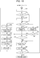
- Figs. 9 and 10 are flowcharts illustrating an example of the pitch bend control processing executed on the basis of the principle described above. This processing is processing in which the CPU 101 in Fig. 1 loads a pitch bend control program stored in the ROM 102 onto the RAM 103 and executes the program.
- the flowcharts in Figs. 9 and 10 are views obtained by expressing, as flowcharts, control time sequences of the wave guide model control unit 201 and the wave guide model calculation unit 202 in Fig.
- the CPU 101 determines whether L2 is larger or smaller than L1, that is, whether to execute bend-down or bend-up in step S1.
- the CPU 101 determines whether the number of delay units k is an even number or an odd number in step S5. Note that "%" is an operation of calculating a remainder obtained by dividing the value of the number of delay units k by 2.
- the number of delay units k is the even number if a result of the operation is 0, and the number of delay units k is the odd number if the result of the operation is not 0.
- the CPU 101 sets a coefficient calculated from the fractional part 1 by the calculation represented by Formula (1) as the filter coefficient g in step S6.
- the CPU 101 sets a coefficient calculated from the fractional part 1 by the calculation represented by Formula (2) as 1-g in step S8.
- step S7 or step S9 there is no carry in the number of delay units k, which is the integer part of the delay length, and thus, the CPU 101 directly executes the all-pass filter calculation of each of the APF 305(#0), the APF 305(#1), and the APF 305(#2) in step S10, and then, updates a sample in step S11. Updating the sample means shifting data in each of the delay units 302 of the delay line 301 one by one to advance a waveform.
- the CPU 101 ends the processing when it is determined in step S12 that L has reached the target value, and repeats the processing while adding the rate r to L until L reaches the target value when it is determined that L has not reached the target value.
- step S7 or step S9 is a case where there is a carry in the number of delay units k, which is the integer part of the delay length.
- the CPU 101 executes the all-pass filter calculation of each of the APF 305(#0), the APF 305(#1), and the APF 305(#2) in step S14.
- the calculation is executed in the APF 305(#1) with the number of delay units k and the filter coefficient of 0, and in the APF 305(#2) with the number of delay units k+1 and the filter coefficient of 1. Since the calculation is started with a value of the feedback delay unit being set to 0 in the APF 305(#2), a signal of i20 is directly output due to the property of the all-pass filter.
- the signals of i20 and i11 are the same. Therefore, at this timing, signals output to the output selection terminals o1 and o2 are equal. Thus, noise is not generated even if the switch 310 switches the output selection terminal from o1 to o2 in step S16.
- step S15 the CPU 101 updates the sample as in step S11.
- the CPU 101 switches the switch 310 to the output selection terminal o2.
- the CPU 101 clears data in the feedback delay unit 307(#0) of the APF 305(#0) to 0 in step S17.
- the CPU 101 reconnects the connection terminals i00 and i01 of the APF 305(#0) to the delay line switch terminals dk+2 and dk+3, respectively, in step S18.
- the filter coefficient g0 of the APF 305(#0) is changed from 0 to 1.
- a state of the wave guide model calculation unit 202 after switching of the connection of the APF 305(#0) is the same as described above with reference to Fig. 6 .
- the process of step S18 is equivalent to the operation of incrementing the number of delay units k, which is the integer part of the delay length, by +1.
- "++" represents an increment operation by +1.
- the CPU 101 After the process of step S18, the CPU 101 returns to the process of step S2 and repeats the operation of increasing the delay length.
- the APF 305(#2) is an object for changing the filter coefficient.
- the APF 305(#0), the APF 305(#1), and the APF 305(#2) become objects of filter coefficient calculation one after another in the ascending order of the annular ring each time the number of delay units k is incremented.
- step S1 of Fig. 9 when L1 > L2, that is, in the case of bend-up, processes in and after step S19 of the flowchart of Fig. 10 is executed.
- L1 > L2 the following differences occur as compared with the case of L1 ⁇ L2.
- the CPU 101 subtracts the rate r from the fractional part 1 in step S19.
- step S24 or step S26 it is determined in step S24 or step S26 whether there is a borrow in the number of delay units k, which is the integer part of the delay length, depending on whether g > 1 or 1-g > 1 is satisfied.
- a case where it is determined that g > 1 or 1-g > 1 is satisfied is a case where there is the borrow in the number of delay units k.
- the CPU 101 further executes the calculation and sample update of each of the APF 305(#0), the APF 305(#1), and the APF 305(#2) in steps S31 and S32.
- the calculation is continued with the filter coefficient of 0 in the APF 305(#0), a signal of i01 is directly output.
- the signals of i10 and i01 are substantially the same. Therefore, noise is not generated even if the output selection terminal is switched from the output selection terminal o1 to the output selection terminal o0 by the switch 310 in step S33.
- the CPU 101 switches the switch 310 to the output selection terminal o0 in step S33.
- the CPU 101 clears data in the feedback delay unit 307(#2) of the APF 305(#2) to 0 in step S34.
- the CPU 101 connects the connection terminals i20 and i21 of the APF 305(#2) to the delay line switch terminals dk-2 and dk-1, respectively, in step S35.
- a state of the wave guide model calculation unit 202 after switching of the connection of the APF 305(#2) is the same as described above with reference to Fig. 8 .
- the process of step S35 is equivalent to the operation of decrementing the number of delay units k, which is the integer part of the delay length, by 1.
- "--" represent a decrement operation by 1.
- the CPU 101 After the process of step S35, the CPU 101 returns to the process of step S19 and repeats the operation of decreasing the delay length.
- the APF 305(#0) is an object for changing the filter coefficient.
- the APF 305(#0), the APF 305(#1), and the APF 305(#2) become objects of the filter coefficient calculation one after another in the descending order of the annular ring each time the number of delay units k is decremented.
- the connection is changed with the filter coefficient of the APF 305 being set to 0, and the calculation is started in a state where the filter coefficient is small when the rate r is sufficiently small as described in step S35 in Fig. 10 .
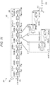
- noise appearing in the next sample is small even if a value on the feedback side is undefined (discontinuous). Therefore, as a modification of the present embodiment, the APF 305(#1) and the APF 305(#2) are calculated with the APF 305(#0) having been removed as illustrated in Fig. 11 , the APF 305(#1) is then reconnected instead of the APF 305(#0) in step S18 of Fig.
- the APF 305(#2) is reconnected to the delay line switch terminals dk-1 and dk in step S35 of Fig. 10 , but the influence of noise is small, and the number of delay units can be changed. In this case, the number of times of multiplication can be reduced by twice.
- the multiplication operation may be left with priority given to uniformity of algorithms and hardware.
- the final output signal y(n) is connected to o1 when no pitch bend occurs during sound generation.
- the output signals of the APF 305(#0) and the APF 305(#2) are not output from the output selection terminals o0 and o2, but are calculated and prepared for the occurrence of the pitch bend during the sound generation described above.
- the plurality of APFs 305 are connected to the respective adjacent delay units 302 in the delay line 301 in advance to prevent undefined data from entering the delay unit 302 in the present embodiment, it is possible to suppress the noise when the number of delay units 302 changes during the sound generation of the wave guide model. In addition, it is possible to reduce the number of times of multiplication in the two APFs 305 other than the APF 305 connected to the first delay unit in the present embodiment.
- the envelope control can be easily applied to the filter coefficient since the filter coefficient can be continuously changed according to the present embodiment.
- FIG. 3 The block diagrams illustrated in the respective drawings described above can be replaced with software.
- software processing can be implemented as a processor calculates and outputs filter coefficients from a mathematical expression for deriving delay lengths of pairs of each of a zeroth to second delay units and each of the APFs 305 (#0 to #2), calculates a waveform with the filter coefficient of the pair of the first delay unit and the APF 305(#1) and applies the waveform to an output.
- FIG. 3 the switching operation of the APF 305 described with reference to Fig.
- software processing can be implemented as the processor periodically outputs the filter coefficients from the mathematical expression for deriving the delay lengths of the pairs of each of the zeroth to second delay units and each of the APFs 305 (#0 to #2) before switching, regards a case where the filter coefficient corresponding to the APF 305(#1) exceeds a predetermined range as switching, and then, outputs filter coefficients from a mathematical expression for deriving delay lengths of pairs of each of new zeroth to second delay units and each of the APFs 305 (#0 to #2) after the switching, calculates a waveform with the filter coefficient of the new pair of the first delay unit and the APF 305(#1), and applies the waveform to an output.
- the control program is stored in the ROM 102 in the above-described embodiment, but is not limited thereto, and may be stored in a removable storage medium, such as a USB memory, a CD, and a DVD, or may be stored in a server.
- the musical sound signal generation device 100 may acquire the control program from such a storage medium or may acquire the control program from the server via a network.
- all-pass filters described in the above embodiment is not limited to three, and four or more all-pass filters may be provided.
- the present invention is not limited to the above-described embodiment, and various modifications can be made in an implementation stage within a scope not departing from a gist thereof.
- functions executed in the above-described embodiment may be suitably combined and implemented as much as possible.
- the above-described embodiment includes different stages, and various inventions can be extracted by combining suitably a plurality of disclosed structural requirements. For example, even when some structural requirements are deleted from all the structural requirements disclosed in the embodiment, a configuration from which the structural requirements have been deleted can be extracted as an invention as long as the effect can be obtained.
Landscapes
- Engineering & Computer Science (AREA)
- Physics & Mathematics (AREA)
- Acoustics & Sound (AREA)
- Multimedia (AREA)
- General Engineering & Computer Science (AREA)
- Electrophonic Musical Instruments (AREA)
Abstract
Description
- The present application claims the benefit of priority of
Japanese Patent Application No. 2021-153006 filed on September 21, 2021 Japanese Patent Application No. 2022-98190 filed on June 17, 2022 Japanese Patent Application No. 2021-153006 Japanese Patent Application No. 2022-98190 - The present disclosure relates to a musical sound signal generation device, a musical sound signal generation method, and a program.
- The number of delay units constituting a wave guide modeling sound source is an integer and is discrete. Therefore, a technique for achieving a delay length of a fraction finer than the integer corresponding to the number of delay units is required in order to determine a strict frequency.
- As a related art for continuously achieving fractional delay lengths in a wide frequency band, for example, there is known a technique of inserting an all-pass filter before a final stage of a delay unit in
JP H6-348277 A - In the above-described related art, however, it is necessary to operate the two all-pass filters such that the delay times are always equal and to perform the weighted addition of the outputs of the two all-pass filters. Thus, an operation of constantly multiplying a filter coefficient twice is executed in each calculation of the two all-pass filters, and a multiplication operation in the weighted addition is also required, so that a total of at least six multiplication operations are required per sample. In a case where, for example, 256 polyphonic sounds are simultaneously generated using such a technique of the wave guide modeling sound source with a large number of multiplication operations (for example, in the case of a modeling sound source of a piano), it is necessary to perform multiplication operations, for example, at least 6 times × 256 polyphonic sounds = 1,536 times of multiplication operations in total per sample, and there is a problem that the amount of calculation for musical sound generation increases as a whole.
- Therefore, one advantage of the present disclosure is to generate a musical sound with a small amount of calculation.
- A musical sound signal generation device continuously connects any one of a connected zeroth delay unit and a connected second delay unit to a fractional delay block and connects at least any one of a new zeroth delay unit and a new second delay unit to at least any one of the fractional delay block other than the fractional delay block connected to a new first delay unit in response to setting any one of the connected zeroth delay unit and the connected second delay unit as the new first delay unit, setting a delay unit in a preceding stage of the new first delay unit as the new zeroth delay unit, and setting a delay unit in a subsequent stage of the new first delay unit as the new second delay unit in accordance with a change in a designated tone pitch.
- According to the present disclosure, it is possible to generate the musical sound with the small amount of calculation.
-
-
Fig. 1 is a block diagram illustrating exemplary hardware of an embodiment of a musical sound signal generation device according to the present disclosure. -
Fig. 2 is a block diagram illustrating exemplary functions implemented by a digital signal processor (DSP) or a wave guide model circuit. -
Fig. 3 is a diagram illustrating an exemplary block configuration of a wave guide model calculation unit. -
Fig. 4 is a diagram illustrating exemplary connections of three sets of all-pass filters (APFs) to a delay line. -
Fig. 5 is an explanatory diagram of an effect of reducing a calculation load in the embodiment. -
Fig. 6 is a diagram illustrating a change in the connections of the three sets of APFs to the delay line when the number of delay units k, which is an integer part of a delay length, increases. -
Fig. 7 is an explanatory view of a method of continuously controlling a filter coefficient. -
Fig. 8 is a diagram illustrating a change in the connections of the three sets of APFs to the delay line when the number of delay units k, which is the integer part of the delay length, decreases. -
Fig. 9 is a flowchart (Part 1) illustrating an example of pitch bend control processing. -
Fig. 10 is a flowchart (Part 2) illustrating an example of the pitch bend control processing. -
Fig. 11 is a diagram illustrating another embodiment of a wave guide model calculation unit. - Hereinafter, modes for carrying out the present disclosure will be described in detail with reference to the drawings. An electronic device includes a musical sound
signal generation device 100, a performance operator (not illustrated), and a speaker. The performance operator corresponds to a key when the electronic device is a keyboard, such as an electronic piano, and corresponds to a mouthpiece when the electronic device is an electronic wind instrument.Fig. 1 is a block diagram illustrating exemplary hardware of an embodiment of the musical soundsignal generation device 100 according to the present disclosure. The musical soundsignal generation device 100 includes: at least one central processing unit (CPU) 101 as a processor; a read only memory (ROM) 102; a random access memory (RAM) 103; a digital signal processor (DSP) or a waveguide model circuit 104; apitch bend sensor 110 and an analog-todigital converter (ADC) 106 to which an output of thepitch bend sensor 110 is connected; avolume sensor 109 and an ADC or adigital input port 105 configured to detect thevolume sensor 109; a tonepitch designation switch 111 and adigital input port 107 to which an output of the tone pitch designation switch is connected; a digitalto-analog converter (DAC)/amplifier 108; and asystem bus 112. TheCPU 101, theROM 102, theRAM 103, the DSP or waveguide model circuit 104, theADC 106, the ADC ordigital input port 105, thedigital input port 107, and the DAC/amplifier 108 are connected to each other by thesystem bus 112. Here, thevolume sensor 109 and the tonepitch designation switch 111 may be the same. For example, in a case where the musical soundsignal generation device 100 is an electronic piano, a switch sensing that a key has been pushed serves as both a tone pitch sensor and a volume sensor. - In the present embodiment, an example of using the
CPU 101 and the DSP 104 is described as an embodiment in which the present disclosure is implemented as software. However, theCPU 101 may play the role of the DSP 104. In addition, the function of the DSP 104 may be implemented by the hardware waveguide model circuit 104.Fig. 2 is a block diagram illustrating exemplary functions implemented by the DSP or waveguide model circuit 104. - A wave guide
model control unit 201, which is a control circuit, receives tone pitch information 203 (for example, a note number depending on a key in the case of the electronic piano) input from the tonepitch designation switch 111 inFig. 1 and bend information (pitch change amount) 204 transmitted from thepitch bend sensor 110 inFig. 1 as input signals, calculates a delay length of a wave guide model corresponding to a frequency f at which a sound needs to be generated, calculates the number of delay units k that is an integer part of the delay length and a filter coefficient g of an all-pass filter (fractional delay block) that determines afractional part 1 of the delay length, and outputs the calculated number of delay units k and the calculated filter coefficient g to a wave guidemodel calculation unit 202. - Here, it is known that there is a relationship of

fractional part 1 of the delay length and the filter coefficient g of the all-pass filter. - In addition, the wave guide
model control unit 201 calculates avolume 207 of an excitationoriginal sound 206 on the basis ofvolume information 205 input from thevolume sensor 109 inFig. 1 . Then, the excitationoriginal sound 206 is multiplied by thevolume 207 by amultiplier 208. Here, the excitationoriginal sound 206 is a signal that serves as a source of resonance in wave guide modeling and is a signal that is recorded in advance and stored in, for example, theROM 102 inFig. 1 , is copied from theROM 102 to theRAM 103 in response to an activation of a system, and is read from theRAM 103 in response to a start of sound generation control, or is a signal synthesized by calculation. - The wave guide
model calculation unit 202 receives the excitationoriginal sound 206 multiplied by thevolume 207 as an input signal x(n) and the delay length (the number of delay units k and the filter coefficient g), performs calculation to be described later with reference toFig. 3 , and outputs amusical sound signal 209. Themusical sound signal 209 is input to the DAC/amplifier 108 inFig. 1 and emitted via a speaker or the like of an electronic device (electronic musical instrument). -
Fig. 3 is a diagram illustrating an exemplary block configuration of the wave guidemodel calculation unit 202 inFig. 2 . InFig. 3 , adelay line 301 includes N (a plurality of)delay units 302 including #0 to #N-1 connected in a cascade manner (in series). Thedelay unit 302 delays an input signal by one sampling time and outputs the delayed signal. A symbol z-1 in each of thedelay units 302 inFig. 3 indicates that a delay operation for one sample in z-conversion is executed. A signal obtained by adding, by anadder 311, a signal obtained by multiplying the input signal x(n) (seeFig. 2 ) generated on the basis of the excitationoriginal sound 206 by a predetermined gain by amultiplier 304 to afeedback signal 303 is input to a delay unit 302(#0) at the head of thedelay line 301. Outputs of thedelay units 302 in thedelay line 301 can be taken out from delay line switch terminals d1 to dN, respectively. - In the present embodiment, the wave guide
model calculation unit 202 includes three all-pass filter circuits (hereinafter referred to as "APF") 305 including #0, #1, and #2. TheAPF 305 is connected to both ends of any of thedelay units 302 in thedelay line 301, thereby operating as the all-pass filter. TheAPF 305 includes: amultiplier 306 that multiplies a signal on an input side of the connecteddelay unit 302 by a feedforward gain g (g0, g1, or g2); anadder 309 that adds a signal on an output side of the connecteddelay unit 302, an output signal of themultiplier 306, and an output signal of amultiplier 308 to be described later and selectively outputs the added output signal to aswitch 310; afeedback delay unit 307 that delays the added output signal by one sampling time; and themultiplier 308 that multiplies an output signal of thefeedback delay unit 307 by a feedback gain -g (-g0, -g1, or -g2) and outputs the multiplied output signal to theadder 309. - Each set of connection terminals i00 and i01 of the APF 305(#0), connection terminals i10 and i11 of the APF 305(#1), and connection terminals i20 and i21 of the APF 305(#2) is connected to delay line switch terminals at both ends of the
same delay unit 302 of thedelay line 301. - In addition, the APF 305(#0), the APF 305(#1), and the APF 305(#2) respectively include sets of the feedforward gain and the feedback gain, that is, (g0 and -g0), (g1 and -g1), and (g2 and -g2). Hereinafter, the feedforward gain and the feedback gain are collectively referred to as a filter coefficient of the all-pass filter.
- The APF 305(#0), the APF 305(#1), and the APF 305(#2) are always connected to the respective
adjacent delay units 302 in thedelay line 301, and the order thereof is controlled to be switched in the order of an annular ring by pitch bend control processing to be described later. - Each output destination of the APF 305(#0), the APF 305(#1), or the APF 305(#2) is connected to each output selection terminal o0, o1, or o2 of the
switch 310, and one of the output selection terminals is selected to output an output signal y(n), whereby themusical sound signal 209 is output. In addition, the output signal y(n) is multiplied by an output feedback gain by themultiplier 304, and the multiplication result is added to the input signal x(n) by theadder 311. -
Fig. 4 is a diagram illustrating exemplary connections of the three sets ofAPFs 305 including #0, #1, and #2 to thedelay line 301 in the wave guidemodel calculation unit 202 inFig. 2 having the configuration ofFig. 3 . As described above, the wave guidemodel control unit 201 inFig. 2 calculates the delay length of the wave guide model corresponding to the frequency f at which a sound needs to be generated on the basis of thetone pitch information 203 input from the tonepitch designation switch 111 inFig. 1 , which is the performance operator of the electronic musical instrument, for example, and then, designates the number of delay units k, which is the integer part of the delay length, to the wave guidemodel calculation unit 202. In addition, the wave guidemodel control unit 201 inFig. 2 calculates the filter coefficient g of theAPF 305 that defines thefractional part 1 of the delay length by calculation represented by Formula (1) described above, and designates the filter coefficient g to the wave guidemodel calculation unit 202. - As a result, in the wave guide
model calculation unit 202 inFig. 4 , delay line switch terminals dk and dk+1 at both ends of a delay unit 302(#k) in thedelay line 301, which is a first delay unit that generates a delay of the integer part of the delay length corresponding to a designated tone pitch designated by the wave guidemodel control unit 201, are respectively connected to the connection terminals i10 and i11 of the APF 305(#1). - In addition, delay line switch terminals dk-1 and dk at both ends of a delay unit 302(#k-1), which is a zeroth delay unit in an immediately preceding stage of the delay unit 302(#k), which is the first delay unit, in the
delay line 301 are respectively connected to the connection terminals i00 and i01 of the APF 305(#0). - Furthermore, delay line switch terminals dk+1 and dk+2 at both ends of a delay unit 302(#k+1), which is a second delay unit in an immediately subsequent stage of the delay unit 302(#k), which is the first delay unit, in the
delay line 301 are respectively connected to the connection terminals i20 and i21 of the APF 305(#2). - The wave guide
model control unit 201 inFig. 2 sets the feedforward gain g and the feedback gain -g of the filter coefficient g, calculated by the calculation represented by Formula (1) to correspond to thefractional part 1 of the delay length corresponding to the designated tone pitch, respectively in the multipliers 306(#1) and 308(#1) of the APF 305(#1). - In addition, a value of 0 that causes a delay of a value of 1 in the fractional part is set as the feedforward gain and the feedback gain of the filter coefficient in both of the multipliers 306(#0) and 308(#0) of the APF 305(#0).
- Further, values of 1 and -1 that cause a delay of a value of 0 of the fractional part are respectively set as the feedforward gain and the feedback gain of the filter coefficient in the multipliers 306(#2) and 308(#2) of the APF 305(#2).
- Then, the
switch 310 causes conduction of the output selection terminal o1. As a result, an output signal of the APF 305(#1) is selected as the output signal y(n) via theswitch 310, whereby themusical sound signal 209 is output. In addition, the output signal y(n) is multiplied by the output feedback gain by themultiplier 304, and the result is added to the input signal x(n) by theadder 311. - As a result of the above control operation, as the
musical sound signal 209, the integer part k of the delay length corresponding to the designated tone pitch is generated by thedelay units 302 including #0 to #k-1 in thedelay line 301, and thefractional part 1 of the delay length is generated by the APF 305(#1) that operates on the basis of the filter coefficient g calculated by the calculation represented by Formula (1). - In this case, a circuit including the
delay line 301 and the APF 305(#1) has flat frequency characteristics, and thus, it is possible to prevent a decrease in amplitude in a high frequency band. -
Fig. 5 is an explanatory diagram of an effect of reducing a calculation load in the embodiment. As described above, the value of 0 that causes the delay of the value of 1 in the fractional part is set as the feedforward gain and the feedback gain of the filter coefficient in both of the multipliers 306(#0) and 308(#0) of the APF 305(#0). Therefore, it is substantially unnecessary for the multipliers 306(#0) and 308(#0) to execute a multiplication operation with a large load, and the APF 305(#0) inFig. 4 is an equivalent circuit illustrated inFig. 5 . That is, it is sufficient for the APF 305(#0) to execute an operation of outputting an output from the delay unit 302(#k-1) in thedelay line 301 via the delay line switch terminal dk directly to the output selection terminal o0 of theswitch 310. - On the other hand, the value of 1 and the value of -1 that cause the delay of the value of 0 of the fractional part are respectively set as the feedforward gain and the feedback gain of the filter coefficient in the multipliers 306(#2) and 308(#2) of the APF 305(#2) as described above. Therefore, it is substantially unnecessary for the multipliers 306(#2) and 308(#2) to execute a multiplication operation with a large load, and the APF 305(#2) in
Fig. 4 is an equivalent circuit illustrated inFig. 5 . That is, it is sufficient for the APF 305(#2) to execute an operation of inputting an output from the delay unit 302(#k) in thedelay line 301 via the delay line switch terminal dk+1 directly to the adder 309(#2), changing a sign of an output of the feedback delay unit 307(#2) by the multiplier 308(#2), and inputting the output with the changed sign to the adder 309(#2). - As described above, the multiplication operation is substantially necessary only in the APF 305(#1) in the present embodiment, and the multiplication operation is unnecessary in the APF 305(#0) and the APF 305(#2). Therefore, the calculation load can be greatly reduced particularly in musical sound generation by the wave guide modeling with a large number of polyphonic sounds as compared with a technique of
JP H6-348277 A - Next, a description will be given regarding a principle of the pitch bend control processing in a case where a player has changed a tone pitch (pitch) of a playing sound being generated by operating the pitch bend sensor 110 (
Fig. 1 ) of the musical instrument. - In
Fig. 2 , the wave guidemodel control unit 201 sequentially calculates a delay length of a new designated tone pitch on the basis of the sequentiallyinput bend information 204, and sequentially outputs the number of delay units k, which is an integer part of the delay length, and the filter coefficient g, calculated by the calculation represented by Formula (1) corresponding to thefractional part 1, to the wave guidemodel calculation unit 202. - Here, if a value of the number of delay units k does not change, only the filter coefficient g changes. This means that a change in wavelength of the
musical sound signal 209 settles within one sampling time. For example, in a case where the player performs a pitch bend operation to decrease a pitch so that thefractional part 1 of a delay length corresponding to a new designated tone pitch sequentially increases, a value of the filter coefficient g calculated by the calculation represented by Formula (1) described above is designated to be sequentially decreased. -
Fig. 6 is a diagram illustrating a change in the connections of the three sets ofAPFs 305 to thedelay line 301 when the number of delay units k, which is the integer part of the delay length, increases. When the player performs the pitch bend operation to decrease the pitch so that thefractional part 1 of the delay length corresponding to the new designated tone pitch sequentially increases and reaches a value of 1, the wave guidemodel control unit 201 inFig. 2 increments a value of the number of delay units k, which is the integer part of the delay length of the designated tone pitch to be output to the wave guidemodel calculation unit 202, by +1. At this time, thefractional part 1 of the delay length becomes 0 due to the increment of the number of delay units k, the value of the filter coefficient g calculated by the calculation represented by Formula (1) becomes 1. - When the value of the number of delay units k designated by the wave guide
model control unit 201 has been incremented by +1 and changed in this manner, in the wave guidemodel calculation unit 202 illustrated inFig. 6 , the operation of the all-pass filter is handed over to the APF 305(#2), which has been connected to the delay line switch terminals dk+1 and dk+2 at both ends so far, with a new delay unit 302(#k+1) in thedelay line 301 corresponding to the changed number of delay units k+1 as a new first delay unit. - In addition, as a result of the handover in
Fig. 6 , theswitch 310 cuts off the conduction of the output selection terminal o1 and newly causes conduction of the output selection terminal o2. - At this time, the value of 1 and the value of -1 that cause the delay of the value of 0 of the fractional part are respectively set as the feedforward gain and the feedback gain of the filter coefficient in the multipliers 306(#2) and 308(#2) of the APF 305(#2) for the operation as described above. Therefore, the above-described operation of switching the operation of the all-pass filter from the APF 305(#1) to the APF 305(#2) matches well with the operation of controlling the
fractional part 1 designated by the wave guidemodel control unit 201 inFig. 2 to 0. - In addition, the APF 305(#2) continuously operates according to actual signals from the delay line switch terminals dk+1 and dk+2, and thus, it is possible to perform control so as not to generate noise at the time of switching the
APF 305. - Here, as the value of the
fractional part 1 increases in the APF 305(#1), the value of the filter coefficient g calculated by the calculation represented by Formula (1) decreases toward 0 as described above. However, when the control is switched from the APF 305(#1) to the APF 305(#2), the operation is started with the value of thefractional part 1 being reset to 0, and thus, it is necessary to cause a jump of the value of the filter coefficient g from the vicinity of 0 to the vicinity of 1 at this moment. Such a discontinuous jump of the value is not so preferable when envelope control is performed on the filter coefficient g. - Therefore, in the present embodiment, in a case where the
delay unit 302 operating as the first delay unit is, for example, an even-numbered delay unit, the filter coefficient g is calculated by the calculation processing represented by Formula (1) described above. - On the other hand, in a case where the
delay unit 302 operating as the first delay unit is, for example, an odd-numbered delay unit, the filter coefficient g is calculated by calculation processing represented by the following Formula (2).
- In this case, coefficients (1-g) and -(1-g) calculated using the coefficient g calculated by the calculation represented by the above Formula (2) are respectively set as a feedforward gain and a feedback gain in the
multipliers - In the example of
Fig. 6 , for example, in a case where the APF 305(#1) has executed the operation of the all-pass filter so far and g and -g have been set as a feedforward gain and a feedback gain in the multipliers 306(#1) and 308(#1), control may be performed such that (1-g) and -(1-g) are set as the feedforward gain and the feedback gain in the multipliers 306(#2) and 308(#2), respectively, when the operation of the all-pass filter is switched from the APF 305(#1) to the APF 305(#2) as described above. -
Fig. 7 is an explanatory view of a method of continuously controlling the filter coefficient g. For example, a case is considered in which the filter coefficient g decreases with an increase of a fraction of a delay length as illustrated inFig. 7(b) by the calculation represented by Formula (1) in a section l1 in which a value of the number of delay units, which is an integer part of the delay length, is k as illustrated inFig. 7(a) . When a value of the filter coefficient g reaches 0 in thesection 11, the value of the number of delay units, which is the integer part of the delay length, is switched from k to k+1, which is asection 12, as illustrated inFig. 7(a) . In thenew section 12, the value of the filter coefficient g is controlled to increase from the minimum value of 0 with the increase of the fraction of the delay length as illustrated inFig. 7(b) by the calculation represented by Formula (2) by the control method described above. - As described above, in the present embodiment, the filter coefficient g can be calculated by switching between the calculation represented by Formula (1) and the calculation represented by Formula (2) depending on whether the
delay unit 302 operating as the first delay unit is an even-numbered (or odd-numbered) delay unit or an odd-numbered (or even-numbered) delay unit, and the filter coefficient g designated to the wave guidemodel calculation unit 202 by the wave guidemodel control unit 201 inFig. 2 can be continuously changed as illustrated inFig. 7(b) by switching between the set of g and -g and the set of (1-g) and -(1-g) to be set in themultipliers APF 305. - As a result, the filter coefficient g changing as illustrated in
Fig. 7(b) can be output as an envelope value by the calculation processing represented by Formula (1) or (2) with thefractional part 1 of the delay length as the input by using an envelope generator circuit generally used in the electronic musical instrument technology. - In
Fig. 6 , in a case where the number of delay units k, which is an integer part of a delay length, increases so that an object that performs the operation of the all-pass filter as a first delay unit is switched from the APF 305(#1) to the new APF 305(#2) as described above, the delay unit 302(#k) that has operated as the first delay unit so far is recognized as a zeroth delay unit in an immediately preceding stage of the delay unit 302(#k+1), which is a new first delay unit, and a value of 0 that causes a delay of a value of 1 of a fractional part as an all-pass filter circuit connected to the zeroth delay unit is set as the feedforward gain and the feedback gain of the filter coefficient in both of the multipliers 306(#1) and 308(#1) of the APF 305(#1) which has been connected to the delay line switch terminals dk and dk+1 on both sides as illustrated inFig. 6 . - In addition, in
Fig. 6 , the delay unit 302(#k+2) is recognized as a second delay unit in an immediately subsequent stage of the delay unit 302(#k+1) which is a new first delay unit, the connection terminals i00 and i01 of the APF 305(#0) are newly connected to the delay line switch terminals dk+2 and dk+3 on both sides, respectively, and a value of 1 and a value of -1 that cause a delay of a value of 0 of a fractional part as an all-pass filter circuit connected to the second delay unit are respectively set as the feedforward gain and the feedback gain of the filter coefficient in the multipliers 306(#0) and 308(#0) of the APF 305(#0). - Note that an output of the
feedback delay unit 307 may be cleared to 0 before the connection of each of theAPFs 305 is switched as described above. -
Fig. 8 is a diagram illustrating a change in the connections of the three sets ofAPFs 305 to thedelay line 301 when the number of delay units k, which is the integer part of the delay length, decreases. When the player performs the pitch bend operation to increase the pitch so that thefractional part 1 of the delay length corresponding to the new designated tone pitch sequentially decreases and reaches a value of 0, the wave guidemodel control unit 201 inFig. 2 decrements a value of the number of delay units k, which is the integer part of the delay length of the designated tone pitch to be output to the wave guidemodel calculation unit 202, by 1. At this time, thefractional part 1 of the delay length becomes the maximum value of 1 due to the decrement of the number of delay units k, the value of the filter coefficient g calculated by the calculation represented by Formula (1) becomes 0. - When the value of the number of delay units k designated by the wave guide
model control unit 201 has been decremented by 1 and changed in this manner, in the wave guidemodel calculation unit 202 illustrated inFig. 8 , the operation of the all-pass filter is handed over to the APF 305(#0), which has been connected to the delay line switch terminals dk-1 and dk at both ends so far, with a new delay unit 302(#k-1) in thedelay line 301 corresponding to the changed number of delay units k-1 as a new first delay unit. - In addition, as a result of the handover in
Fig. 8 , theswitch 310 cuts off the conduction of the output selection terminal o1 and newly causes conduction of the output selection terminal o0. - At this time, the value of 0 that cause the delay of the value of 1 of the fractional part is set as the feedforward gain and the feedback gain of the filter coefficient in both the multipliers 306(#0) and 308(#0) of the APF 305(#0) for the operation as described above. Therefore, the above-described operation of switching the operation of the all-pass filter from the APF 305(#1) to the APF 305(#0) matches well with the operation of controlling the
fractional part 1 designated by the wave guidemodel control unit 201 inFig. 2 to 1 . - In addition, the APF 305(#0) continuously operates according to actual signals from the delay line switch terminals dk-1 and dk, and thus, it is possible to perform control so as not to generate noise at the time of switching the
APF 305. - Here, as the value of the
fractional part 1 decreases in the APF 305(#1), the value of the filter coefficient g calculated by the calculation represented by Formula (1) increases toward 1 as described above. However, when the control is switched from the APF 305(#1) to the APF 305(#0), the operation is started with the value of thefractional part 1 being set to 1, and thus, it is necessary to cause a jump of the value of the filter coefficient g from the vicinity of 1 to the vicinity of 0 at this moment. Such a nonlinear jump of the value is not so preferable when envelope control is performed on the filter coefficient g even in the case where the value of the number of delay units k, which is the integer part of the delay length, decreases as in the case where the value of the number of delay units k, which is the integer part of the delay length, increases. - Therefore, in the present embodiment, control is performed to calculate the filter coefficient g by switching between the calculation represented by Formula (1) described above and the calculation represented by Formula (2) depending on whether the
delay unit 302 operating as the first delay unit is an even-numbered (or odd-numbered) delay unit or an odd-numbered (or even-numbered) delay unit, and to switch between the set of g and -g and the set of (1-g) and -(1-g) to be set in themultipliers APF 305 as in the case where the value of the number of delay units k, which is the integer part of the delay length, increases. - In the example of
Fig. 8 , for example, in a case where the APF 305(#1) has executed the operation of the all-pass filter so far and g and -g have been set as a feedforward gain and a feedback gain in the multipliers 306(#1) and 308(#1), control may be performed such that (1-g) and -(1-g) are set as the feedforward gain and the feedback gain in the multipliers 306(#0) and 308(#0), respectively, when the operation of the all-pass filter is switched from the APF 305(#1) to the APF 305(#0) as described above. - For example, in
Fig. 7 described above, a case is considered in which the filter coefficient g increases with a decrease of a fraction of a delay length as illustrated inFig. 7(b) by the calculation represented by Formula (1) in a section l1 in which a value of the number of delay units, which is an integer part of the delay length, is k as illustrated inFig. 7(a) . When a value of the filter coefficient g reaches 1 in thesection 11, the value of the number of delay units, which is the integer part of the delay length, is switched from k to k-1, which is asection 10, as illustrated inFig. 7(a) . In thenew section 10, the value of the filter coefficient g is controlled to decrease from the maximum value of 1 with the decrease of the fraction of the delay length as illustrated inFig. 7(b) by the calculation represented by Formula (2) by the control method described above. - As described above, in the present embodiment, even in the case where the value of the number of delay units k, which is the integer part of the delay length, decreases, it is possible to calculate the filter coefficient g by switching between the calculation represented by Formula (1) and the calculation represented by Formula (2) depending on whether the
delay unit 302 operating as the first delay unit is an even-numbered (or odd-numbered) delay unit or an odd-numbered (or even-numbered) delay unit, and to continuously change the filter coefficient g, designated to the wave guidemodel calculation unit 202 by the wave guidemodel control unit 201 inFig. 2 , as illustrated inFig. 7(b) by switching between the set of g and -g and the set of (1-g) and -(1-g) to be set in themultipliers APF 305 as in the case where the value of the number of delay units k, which is the integer part of the delay length, increases. - As a result, the filter coefficient g changing as illustrated in
Fig. 7(b) can be output as an envelope value by the calculation processing represented by Formula (1) or (2) with thefractional part 1 of the delay length as the input by using an envelope generator circuit generally used in the electronic musical instrument technology. - In
Fig. 8 , in a case where the number of delay units k, which is an integer part of a delay length, decreases so that an object that performs the operation of the all-pass filter as a first delay unit is switched from the APF 305(#1) to the new APF 305(#0) as described above, the delay unit 302(#k) that has operated as the first delay unit so far is recognized as a second delay unit in an immediately subsequent stage of the delay unit 302(#k-1), which is a new first delay unit, and a value of 1 and a value of -1 that cause a delay of a value of 0 of a fractional part as an all-pass filter circuit connected to the second delay unit are respectively set as the feedforward gain and the feedback gain of the filter coefficient in both of the multipliers 306(#1) and 308(#1) of the APF 305(#1) which has been connected to the delay line switch terminals dk and dk+1 on both sides as illustrated inFig. 8 . - In addition, in
Fig. 8 , the delay unit 302(#k-2) is recognized as a zeroth delay unit in an immediately preceding stage of the delay unit 302(#k-1) which is a new first delay unit, the connection terminals i20 and i21 of the APF 305(#2) are newly connected to the delay line switch terminals dk-2 and dk-1 on both sides, respectively, and a value of 0 that causes a delay of a value of 1 of a fractional part as an all-pass filter circuit connected to the zeroth delay unit is set as the feedforward gain and the feedback gain of the filter coefficient in both the multipliers 306(#2) and 308(#2) of the APF 305(#2). - Note that the output of the
feedback delay unit 307 may be cleared to 0 before the connection of each of theAPFs 305 is switched as described above, which is similar to the case ofFig. 6 . -
Figs. 9 and10 are flowcharts illustrating an example of the pitch bend control processing executed on the basis of the principle described above. This processing is processing in which theCPU 101 inFig. 1 loads a pitch bend control program stored in theROM 102 onto theRAM 103 and executes the program. The flowcharts inFigs. 9 and10 are views obtained by expressing, as flowcharts, control time sequences of the wave guidemodel control unit 201 and the wave guidemodel calculation unit 202 inFig. 2 in a case where a value of the number of delay units k, which is an integer part of a delay length of a designated tone pitch, and thefractional part 1 is changed from L1 to L2 by thepitch bend sensor 110 after sound generation when the APF 305(#0) is connected to both the ends of the delay unit 302(#k-1), the APF 305(#1) is connected to both the ends of the delay unit 302(#k), and the APF 305(#2) is connected to both the ends of the delay unit 302(#k+1). - When pitch bend is started, the
CPU 101 determines whether L2 is larger or smaller than L1, that is, whether to execute bend-down or bend-up in step S1. - When L1 < L2, that is, in the case of the bend-down, the
CPU 101 adds a rate r to thefractional part 1 of the delay length in step S2. Note that "+=" represents an operation of adding a variable value on the right side to a variable value on the left side. - When L which is a value of the
fractional part 1 and the number of delay units k which is an integer part of a delay length, is larger than a target value in step S3, theCPU 101 causes thefractional part 1 to coincide with 12 for coincidence with the target value in step S4. - Next, the
CPU 101 determines whether the number of delay units k is an even number or an odd number in step S5. Note that "%" is an operation of calculating a remainder obtained by dividing the value of the number of delay units k by 2. The number of delay units k is the even number if a result of the operation is 0, and the number of delay units k is the odd number if the result of the operation is not 0. - When k is the even number, the
CPU 101 sets a coefficient calculated from thefractional part 1 by the calculation represented by Formula (1) as the filter coefficient g in step S6. - When k is the odd number, the
CPU 101 sets a coefficient calculated from thefractional part 1 by the calculation represented by Formula (2) as 1-g in step S8. - Thereafter, when g < 0 or 1-g < 0 is not satisfied in step S7 or step S9, there is no carry in the number of delay units k, which is the integer part of the delay length, and thus, the
CPU 101 directly executes the all-pass filter calculation of each of the APF 305(#0), the APF 305(#1), and the APF 305(#2) in step S10, and then, updates a sample in step S11. Updating the sample means shifting data in each of thedelay units 302 of thedelay line 301 one by one to advance a waveform. - The
CPU 101 ends the processing when it is determined in step S12 that L has reached the target value, and repeats the processing while adding the rate r to L until L reaches the target value when it is determined that L has not reached the target value. - A case where g < 0 or 1-g < 0 is satisfied in step S7 or step S9 is a case where there is a carry in the number of delay units k, which is the integer part of the delay length. In this case, the
CPU 101 sets g = 0 in step S13. - In this state, the
CPU 101 executes the all-pass filter calculation of each of the APF 305(#0), the APF 305(#1), and the APF 305(#2) in step S14. In this case, the calculation is executed in the APF 305(#1) with the number of delay units k and the filter coefficient of 0, and in the APF 305(#2) with the number of delay units k+1 and the filter coefficient of 1. Since the calculation is started with a value of the feedback delay unit being set to 0 in the APF 305(#2), a signal of i20 is directly output due to the property of the all-pass filter. On the other hand, the calculation is executed with g = 0 in the APF 305(#1), and thus, a signal of i11 is directly output. The signals of i20 and i11 are the same. Therefore, at this timing, signals output to the output selection terminals o1 and o2 are equal. Thus, noise is not generated even if theswitch 310 switches the output selection terminal from o1 to o2 in step S16. - Thereafter, in step S15, the
CPU 101 updates the sample as in step S11. - Subsequently, the
CPU 101 switches theswitch 310 to the output selection terminal o2. - Thereafter, the
CPU 101 clears data in the feedback delay unit 307(#0) of the APF 305(#0) to 0 in step S17. - Thereafter, the
CPU 101 reconnects the connection terminals i00 and i01 of the APF 305(#0) to the delay line switch terminals dk+2 and dk+3, respectively, in step S18. In addition, the filter coefficient g0 of the APF 305(#0) is changed from 0 to 1. - A state of the wave guide
model calculation unit 202 after switching of the connection of the APF 305(#0) is the same as described above with reference toFig. 6 . The process of step S18 is equivalent to the operation of incrementing the number of delay units k, which is the integer part of the delay length, by +1. In the drawing, "++" represents an increment operation by +1. - After the process of step S18, the
CPU 101 returns to the process of step S2 and repeats the operation of increasing the delay length. At this time, the APF 305(#2) is an object for changing the filter coefficient. Thereafter, the APF 305(#0), the APF 305(#1), and the APF 305(#2) become objects of filter coefficient calculation one after another in the ascending order of the annular ring each time the number of delay units k is incremented. - In step S1 of
Fig. 9 , when L1 > L2, that is, in the case of bend-up, processes in and after step S19 of the flowchart ofFig. 10 is executed. When L1 > L2, the following differences occur as compared with the case of L1 < L2. - First, the
CPU 101 subtracts the rate r from thefractional part 1 in step S19. In the drawing, "-=" represents an operation of subtracting a variable value on the right side from a variable value on the left side. - In addition, it is determined in step S24 or step S26 whether there is a borrow in the number of delay units k, which is the integer part of the delay length, depending on whether g > 1 or 1-g > 1 is satisfied.
- A case where it is determined that g > 1 or 1-g > 1 is satisfied is a case where there is the borrow in the number of delay units k. In this case, the
CPU 101 sets g = 1 in step S30. - The
CPU 101 further executes the calculation and sample update of each of the APF 305(#0), the APF 305(#1), and the APF 305(#2) in steps S31 and S32. In the subsequent state, the calculation is performed with the filter coefficient g = 1 in the APF 305(#1), and a signal of i10 is output substantially without any change although there is some influence of feedback. The calculation is continued with the filter coefficient of 0 in the APF 305(#0), a signal of i01 is directly output. The signals of i10 and i01 are substantially the same. Therefore, noise is not generated even if the output selection terminal is switched from the output selection terminal o1 to the output selection terminal o0 by theswitch 310 in step S33. - The
CPU 101 switches theswitch 310 to the output selection terminal o0 in step S33. - Thereafter, the
CPU 101 clears data in the feedback delay unit 307(#2) of the APF 305(#2) to 0 in step S34. - Thereafter, the
CPU 101 connects the connection terminals i20 and i21 of the APF 305(#2) to the delay line switch terminals dk-2 and dk-1, respectively, in step S35. - A state of the wave guide
model calculation unit 202 after switching of the connection of the APF 305(#2) is the same as described above with reference toFig. 8 . The process of step S35 is equivalent to the operation of decrementing the number of delay units k, which is the integer part of the delay length, by 1. In the drawing, "--" represent a decrement operation by 1. - After the process of step S35, the
CPU 101 returns to the process of step S19 and repeats the operation of decreasing the delay length. At this time, the APF 305(#0) is an object for changing the filter coefficient. Thereafter, the APF 305(#0), the APF 305(#1), and the APF 305(#2) become objects of the filter coefficient calculation one after another in the descending order of the annular ring each time the number of delay units k is decremented. - In pitch change processing in which the delay length decreases, the connection is changed with the filter coefficient of the
APF 305 being set to 0, and the calculation is started in a state where the filter coefficient is small when the rate r is sufficiently small as described in step S35 inFig. 10 . Thus, noise appearing in the next sample is small even if a value on the feedback side is undefined (discontinuous). Therefore, as a modification of the present embodiment, the APF 305(#1) and the APF 305(#2) are calculated with the APF 305(#0) having been removed as illustrated inFig. 11 , the APF 305(#1) is then reconnected instead of the APF 305(#0) in step S18 ofFig. 9 , and the APF 305(#2) is reconnected to the delay line switch terminals dk-1 and dk in step S35 ofFig. 10 , but the influence of noise is small, and the number of delay units can be changed. In this case, the number of times of multiplication can be reduced by twice. - Although it has been described that the number of times of multiplication can be reduced in the APF 305(#0) and the APF 305(#2) in
Fig. 5 , the multiplication operation may be left with priority given to uniformity of algorithms and hardware. The final output signal y(n) is connected to o1 when no pitch bend occurs during sound generation. At this time, the output signals of the APF 305(#0) and the APF 305(#2) are not output from the output selection terminals o0 and o2, but are calculated and prepared for the occurrence of the pitch bend during the sound generation described above. - As described above, since the plurality of
APFs 305 are connected to the respectiveadjacent delay units 302 in thedelay line 301 in advance to prevent undefined data from entering thedelay unit 302 in the present embodiment, it is possible to suppress the noise when the number ofdelay units 302 changes during the sound generation of the wave guide model. In addition, it is possible to reduce the number of times of multiplication in the twoAPFs 305 other than theAPF 305 connected to the first delay unit in the present embodiment. - Then, it is possible to eliminate the frequency dependence of the amplitude and to suppress generation of noise with a small amount of calculation when the number of connections of the delay units changes by using the fractional delay block, such as the all-pass filter, in a wave guide modeling sound source according to the present embodiment. Specifically, there is an advantage in that the number of times of multiplication is reduced by up to four times per one wave guide model. This is because there are about 230 strings in the case of a piano, for example, and the multiplication is reduced by 920 times if all the strings are modeled and operated.
- In addition, the envelope control can be easily applied to the filter coefficient since the filter coefficient can be continuously changed according to the present embodiment.
- The block diagrams illustrated in the respective drawings described above can be replaced with software. For example, in a case where the entire configuration of
Fig. 3 is replaced with software, software processing can be implemented as a processor calculates and outputs filter coefficients from a mathematical expression for deriving delay lengths of pairs of each of a zeroth to second delay units and each of the APFs 305 (#0 to #2), calculates a waveform with the filter coefficient of the pair of the first delay unit and the APF 305(#1) and applies the waveform to an output. In addition, regarding the switching operation of theAPF 305 described with reference toFig. 6 , software processing can be implemented as the processor periodically outputs the filter coefficients from the mathematical expression for deriving the delay lengths of the pairs of each of the zeroth to second delay units and each of the APFs 305 (#0 to #2) before switching, regards a case where the filter coefficient corresponding to the APF 305(#1) exceeds a predetermined range as switching, and then, outputs filter coefficients from a mathematical expression for deriving delay lengths of pairs of each of new zeroth to second delay units and each of the APFs 305 (#0 to #2) after the switching, calculates a waveform with the filter coefficient of the new pair of the first delay unit and the APF 305(#1), and applies the waveform to an output. Furthermore, it is also possible to combine the embodiment using the circuit with software, and replace a part of the circuit with the software. - The control program is stored in the
ROM 102 in the above-described embodiment, but is not limited thereto, and may be stored in a removable storage medium, such as a USB memory, a CD, and a DVD, or may be stored in a server. The musical soundsignal generation device 100 may acquire the control program from such a storage medium or may acquire the control program from the server via a network. - In addition, the number of all-pass filters described in the above embodiment is not limited to three, and four or more all-pass filters may be provided.
- In addition, the present invention is not limited to the above-described embodiment, and various modifications can be made in an implementation stage within a scope not departing from a gist thereof. In addition, functions executed in the above-described embodiment may be suitably combined and implemented as much as possible. The above-described embodiment includes different stages, and various inventions can be extracted by combining suitably a plurality of disclosed structural requirements. For example, even when some structural requirements are deleted from all the structural requirements disclosed in the embodiment, a configuration from which the structural requirements have been deleted can be extracted as an invention as long as the effect can be obtained.
Claims (16)
- A musical sound signal generation device (100) comprising:a delay line (301) provided with a plurality of delay units (302) which are connected in a cascade manner and respectively delay input signals (x(n)) by a first delay length;at least three fractional delay blocks (305) each of which is connected to correspond to any delay unit (302) among the plurality of delay units (302) and delays an input signal (x(n)) by a second delay length equal to or less than the first delay length; andat least one processor (101) that sets any one of the plurality of delay units (302) as a first delay unit (302) which generates a delay corresponding to a designated tone pitch, sets a delay unit in a preceding stage of the first delay unit (302) among the plurality of delay units (302) as a zeroth delay unit (302), and sets a delay unit in a subsequent stage of the first delay unit (302) among the plurality of delay units (302) as a second delay unit (302),wherein the at least one processor (101)connects the at least three fractional delay blocks (305) to the first delay unit (302), the zeroth delay unit (302), and the second delay unit (302), respectively, andcontinuously connects any one of the connected zeroth delay unit (302) and the connected second delay unit (302) to the fractional delay block (305) and connects at least any one of a new zeroth delay unit (302) and a new second delay unit (302) to at least any one of the fractional delay blocks (305) other than the fractional delay block (305) connected to a new first delay unit (302) in response to setting any one of the connected zeroth delay unit (302) and the connected second delay unit (302) as the new first delay unit (302), setting a delay unit in a preceding stage of the new first delay unit (302) as the new zeroth delay unit (302), and setting a delay unit in a subsequent stage of the new first delay unit (302) as the new second delay unit (302) in accordance with a change in the designated tone pitch.
- The musical sound signal generation device (100) according to claim 1, wherein
each of the at least three fractional delay blocks (305) operates as an all-pass filter block together with the delay unit (302) corresponding to the fractional delay block (305). - The musical sound signal generation device (100) according to claim 2, whereinthe at least one processor (101)sets a filter coefficient corresponding to the second delay length, which is a fractional part of a delay length corresponding to the designated tone pitch, in the all-pass filter block which is the fractional delay block (305) corresponding to the first delay unit (302),sets filter coefficients having a value of 0 and a value of 1, which correspond to the second delay length having a value of 1 and a value of 0, in the all-pass filter block which is the fractional delay block (305) corresponding to the zeroth delay unit (302) and the all-pass filter block which is the fractional delay block (305) corresponding to the second delay unit (302), respectively, andoutputs an output of the all-pass filter block, which is the fractional delay block (305) corresponding to the first delay unit (302), as a musical sound signal (209) and a feedback signal (303) to the input of the delay line (301).
- The musical sound signal generation device (100) according to any one of claims 1 to 3, whereinwhen a fractional part of the delay length is denoted by l, the at least one processor (101),sets a coefficient g calculated by calculation represented by a calculation formula of
 as the filter coefficient corresponding to the second delay length which is the fractional part of the delay length corresponding to the designated tone pitch,in a case where the first delay unit (302) is an even-numbered or odd-numbered delay unit, andsets, as the filter coefficient, a coefficient (1-g) calculated by using a coefficient g calculated by calculation represented by a calculation formula of
 in a case where the first delay unit (302) is an odd-numbered or even-numbered delay unit,wherein the musical sound signal generation device (100) further comprising an envelope generator circuit configured to receive, as an input, the fractional part 1 of the delay length and outputs, as an envelope value, the coefficient g that changes as represented by the calculation formula of Formula (1) or (2).
 - The musical sound signal generation device (100) according to any one of claims 1 to 4, whereinthe fractional delay block (305) to which both ends of the zeroth delay unit (302) are connected executes an operation of outputting an output of the zeroth delay unit (302), without any change, andthe fractional delay block (305) to which both ends of the second delay unit (302) are connected executes an operation of outputting an input value in each of multiplication operations without any change or with a changed sign as an output value in the multiplication operation, instead of the multiplication operations of multiplying a value of 1 or a value of -1 corresponding to the filter coefficient having a value of 1 which corresponds to the second delay length having a value of 0.
- An electronic device comprising:the musical sound signal generation device (100) according to any one of claims 1 to 5; andan operator.
- A musical sound signal generation method comprising:connecting at least three fractional delay blocks (305) each of which is connected to correspond to one of a plurality of delay units (302) of a delay line (301) and delays an input signal (x(n)) by a second delay length, equal to or less than a first delay length, respectively to a first delay unit (302) which is the delay unit (302) that generates a delay corresponding to a designated tone pitch among the plurality of delay units (302), a zeroth delay unit (302) corresponding to a preceding stage of the first delay unit (302) among the plurality of delay units (302), and a second delay unit (302) corresponding to a subsequent stage of the first delay unit (302) among the plurality of delay units (302), the plurality of delay units (302) being connected in a cascade manner, and each delaying the input signal (x(n)) by the first delay length; andcontinuously connecting any one of the connected zeroth delay unit (302) and the connected second delay unit (302) to the fractional delay block (305) and connecting at least any one of a new zeroth delay unit (302) and a new second delay unit (302) to at least any one of the fractional delay block (305) other than the fractional delay block (305) connected to a new first delay unit (302) in response to setting any one of the connected zeroth delay unit (302) and the connected second delay unit (302) as the new first delay unit (302), setting a delay unit in a preceding stage of the new first delay unit (302) as the new zeroth delay unit (302), and setting a delay unit in a subsequent stage of the new first delay unit (302) as the new second delay unit (302) in accordance with a change in the designated tone pitch.
- The musical sound signal generation method according to claim 7, further comprising
causing each of the at least three fractional delay blocks (305) to operate as an all-pass filter block together with the delay unit (302) corresponding to the fractional delay block (305). - The musical sound signal generation method according to claim 8, further comprising:setting a filter coefficient corresponding to the second delay length, which is a fractional part of a delay length corresponding to the designated tone pitch, in the all-pass filter block which is the fractional delay block (305) corresponding to the first delay unit (302),setting filter coefficients having a value of 0 and a value of 1, which correspond to the second delay length having a value of 1 and a value of 0, in the all-pass filter block which is the fractional delay block (305) corresponding to the zeroth delay unit (302) and the all-pass filter block which is the fractional delay block (305) corresponding to the second delay unit (302), respectively, andoutputting an output of the all-pass filter block, which is the fractional delay block (305) corresponding to the first delay unit (302), as a musical sound signal (209) and a feedback signal (303) to the input of the delay line (301).
- The musical sound signal generation method according to any one of claims 7 to 9, further comprising:when a fractional part of the delay length is denoted by l,setting a coefficient g calculated by calculation represented by a calculation formula of
 as the filter coefficient corresponding to the second delay length which is the fractional part of the delay length corresponding to the designated tone pitchin a case where the first delay unit (302) is an even-numbered or odd-numbered delay unit, andsetting, as the filter coefficient, a coefficient (1-g) calculated by using a coefficient g calculated by calculation represented by a calculation formula of
 in a case where the first delay unit (302) is an odd-numbered or even-numbered delay unit; andreceiving, as an input, the fractional part 1 of the delay length and outputting, as an envelope value, the coefficient g that changes as represented by the calculation formula of Formula (1) or (2).
 - The musical sound signal generation method according to any one of claims 7 to 10, whereinthe fractional delay block (305) to which both ends of the zeroth delay unit (302) are connected executes an operation of outputting an output of the zeroth delay unit (302), without any change, andthe fractional delay block (305) to which both ends of the second delay unit (302) are connected executes an operation of outputting an input value in each of multiplication operations without any change or with a changed sign as an output value in the multiplication operation, instead of the multiplication operations of multiplying a value of 1 or a value of -1 corresponding to the filter coefficient having a value of 1 which corresponds to the second delay length having a value of 0.
- A program for causing a computer to execute:connecting at least three fractional delay blocks (305) each of which is connected to correspond to one of a plurality of delay units (302) of a delay line (301) and delays an input signal (x(n)) by a second delay length, equal to or less than a first delay length, respectively to a first delay unit (302) which is the delay unit (302) that generates a delay corresponding to a designated tone pitch among the plurality of delay units (302), a zeroth delay unit (302) corresponding to a preceding stage of the first delay unit (302) among the plurality of delay units (302), and a second delay unit (302) corresponding to a subsequent stage of the first delay unit (302) among the plurality of delay units (302), the plurality of delay units (302) being connected in a cascade manner, and each delaying the input signal (x(n)) by the first delay length; andcontinuously connecting any one of the connected zeroth delay unit (302) and the connected second delay unit (302) to the fractional delay block (305) and connecting at least any one of a new zeroth delay unit (302) and a new second delay unit (302) to at least any one of the fractional delay block (305) other than the fractional delay block (305) connected to a new first delay unit (302) in response to setting any one of the connected zeroth delay unit (302) and the connected second delay unit (302) as the new first delay unit (302), setting a delay unit in a preceding stage of the new first delay unit (302) as the new zeroth delay unit (302), and setting a delay unit in a subsequent stage of the new first delay unit (302) as the new second delay unit (302) in accordance with a change in the designated tone pitch.
- The program according to claim 12, further causing the computer to execute
causing each of the at least three fractional delay blocks (305) to operate as an all-pass filter block together with the delay unit (302) corresponding to the fractional delay block (305). - The program according to claim 12, further causing the computer to execute:setting a filter coefficient corresponding to the second delay length, which is a fractional part of a delay length corresponding to the designated tone pitch, in the all-pass filter block which is the fractional delay block (305) corresponding to the first delay unit (302),setting filter coefficients having a value of 0 and a value of 1, which correspond to the second delay length having a value of 1 and a value of 0, in the all-pass filter block which is the fractional delay block (305) corresponding to the zeroth delay unit (302) and the all-pass filter block which is the fractional delay block (305) corresponding to the second delay unit (302), respectively, andoutputting an output of the all-pass filter block, which is the fractional delay block (305) corresponding to the first delay unit (302), as a musical sound signal (209) and a feedback signal (303) to the input of the delay line (301).
- The program according to any one of claims 12 to 14, further causing the computer to execute:when a fractional part of the delay length is denoted by l,setting a coefficient g calculated by calculation represented by a calculation formula of
 as the filter coefficient corresponding to the second delay length which is the fractional part of the delay length corresponding to the designated tone pitchin a case where the first delay unit (302) is an even-numbered or odd-numbered delay unit, andsetting, as the filter coefficient, a coefficient (1-g) calculated by using a coefficient g calculated by calculation represented by a calculation formula of
 in a case where the first delay unit (302) is an odd-numbered or even-numbered delay unit; andreceiving, as an input, the fractional part 1 of the delay length and outputting, as an envelope value, the coefficient g that changes as represented by the calculation formula of Formula (1) or (2).
 - The program according to any one of claims 12 to 15, further causing the computer to execute:causing the fractional delay block (305) to which both ends of the zeroth delay unit (302) are connected to execute an operation of outputting an output of the zeroth delay unit (302), without any change, andcausing the fractional delay block (305) to which both ends of the second delay unit (302) are connected to execute an operation of outputting an input value in each of multiplication operations without any change or with a changed sign as an output value in the multiplication operation, instead of the multiplication operations of multiplying a value of 1 or a value of -1 corresponding to the filter coefficient having a value of 1 which corresponds to the second delay length having a value of 0
Applications Claiming Priority (2)
| Application Number | Priority Date | Filing Date | Title |
|---|---|---|---|
| JP2021153006 | 2021-09-21 | ||
| JP2022098190A JP7424411B2 (en) | 2021-09-21 | 2022-06-17 | Musical tone signal generation device, electronic device, musical tone signal generation method, and program |
Publications (2)
| Publication Number | Publication Date |
|---|---|
| EP4152311A1 true EP4152311A1 (en) | 2023-03-22 |
| EP4152311B1 EP4152311B1 (en) | 2025-04-09 |
Family
ID=85777195
Family Applications (1)
| Application Number | Title | Priority Date | Filing Date |
|---|---|---|---|
| EP22195619.6A Active EP4152311B1 (en) | 2021-09-21 | 2022-09-14 | Musical sound signal generation device, musical sound signal generation method, and program |
Country Status (4)
| Country | Link |
|---|---|
| US (1) | US12175956B2 (en) |
| EP (1) | EP4152311B1 (en) |
| JP (2) | JP7424411B2 (en) |
| CN (1) | CN115841807A (en) |
Families Citing this family (1)
| Publication number | Priority date | Publication date | Assignee | Title |
|---|---|---|---|---|
| JP7424411B2 (en) * | 2021-09-21 | 2024-01-30 | カシオ計算機株式会社 | Musical tone signal generation device, electronic device, musical tone signal generation method, and program |
Citations (6)
| Publication number | Priority date | Publication date | Assignee | Title |
|---|---|---|---|---|
| JPH06348277A (en) | 1993-06-07 | 1994-12-22 | Yamaha Corp | Musical sound signal synthetic device |
| US5496964A (en) * | 1993-03-26 | 1996-03-05 | Yamaha Corporation | Tone generator for electronic musical instrument including multiple feedback paths |
| US5763803A (en) * | 1996-03-12 | 1998-06-09 | Roland Kabushiki Kaisha | Effect adding system capable of simulating tones of stringed instruments |
| EP0979463A1 (en) * | 1996-05-09 | 2000-02-16 | The Board Of Trustees Of The Leland Stanford Junior University | System and method for generating fractional length delay lines in a digital signal processing system |
| JP2021153006A (en) | 2020-03-24 | 2021-09-30 | 株式会社豊田自動織機 | Fuel supply device |
| JP2022098190A (en) | 2020-12-21 | 2022-07-01 | 住友ゴム工業株式会社 | tire |
Family Cites Families (12)
| Publication number | Priority date | Publication date | Assignee | Title |
|---|---|---|---|---|
| US5157214A (en) * | 1989-04-10 | 1992-10-20 | Matsushita Electric Industrial Co., Ltd. | Musical sound synthesizing apparatus |
| JP2727883B2 (en) * | 1992-08-20 | 1998-03-18 | ヤマハ株式会社 | Music synthesizer |
| US5432856A (en) * | 1992-09-30 | 1995-07-11 | Kabushiki Kaisha Kawai Gakki Seisakusho | Sound effect-creating device |
| JPH0792970A (en) * | 1993-09-24 | 1995-04-07 | Matsushita Electric Ind Co Ltd | Pitch change adding device |
| JP3282573B2 (en) * | 1997-11-28 | 2002-05-13 | ヤマハ株式会社 | Variable delay device and method |
| US6978027B1 (en) * | 2000-04-11 | 2005-12-20 | Creative Technology Ltd. | Reverberation processor for interactive audio applications |
| JP2003122368A (en) * | 2001-10-15 | 2003-04-25 | Yamaha Corp | Musical sound signal synthesizing method, musical sound signal synthesizer and program |
| US8345887B1 (en) * | 2007-02-23 | 2013-01-01 | Sony Computer Entertainment America Inc. | Computationally efficient synthetic reverberation |
| JP6176132B2 (en) * | 2014-01-31 | 2017-08-09 | ヤマハ株式会社 | Resonance sound generation apparatus and resonance sound generation program |
| JP6648457B2 (en) * | 2015-09-25 | 2020-02-14 | カシオ計算機株式会社 | Electronic musical instrument, sound waveform generation method, and program |
| JP6806120B2 (en) * | 2018-10-04 | 2021-01-06 | カシオ計算機株式会社 | Electronic musical instruments, musical tone generation methods and programs |
| JP7424411B2 (en) * | 2021-09-21 | 2024-01-30 | カシオ計算機株式会社 | Musical tone signal generation device, electronic device, musical tone signal generation method, and program |
-
2022
- 2022-06-17 JP JP2022098190A patent/JP7424411B2/en active Active
- 2022-09-14 CN CN202211119330.3A patent/CN115841807A/en active Pending
- 2022-09-14 EP EP22195619.6A patent/EP4152311B1/en active Active
- 2022-09-14 US US17/944,970 patent/US12175956B2/en active Active
-
2024
- 2024-01-17 JP JP2024004932A patent/JP7673844B2/en active Active
Patent Citations (6)
| Publication number | Priority date | Publication date | Assignee | Title |
|---|---|---|---|---|
| US5496964A (en) * | 1993-03-26 | 1996-03-05 | Yamaha Corporation | Tone generator for electronic musical instrument including multiple feedback paths |
| JPH06348277A (en) | 1993-06-07 | 1994-12-22 | Yamaha Corp | Musical sound signal synthetic device |
| US5763803A (en) * | 1996-03-12 | 1998-06-09 | Roland Kabushiki Kaisha | Effect adding system capable of simulating tones of stringed instruments |
| EP0979463A1 (en) * | 1996-05-09 | 2000-02-16 | The Board Of Trustees Of The Leland Stanford Junior University | System and method for generating fractional length delay lines in a digital signal processing system |
| JP2021153006A (en) | 2020-03-24 | 2021-09-30 | 株式会社豊田自動織機 | Fuel supply device |
| JP2022098190A (en) | 2020-12-21 | 2022-07-01 | 住友ゴム工業株式会社 | tire |
Also Published As
| Publication number | Publication date |
|---|---|
| JP2023046241A (en) | 2023-04-03 |
| JP7673844B2 (en) | 2025-05-09 |
| JP7424411B2 (en) | 2024-01-30 |
| EP4152311B1 (en) | 2025-04-09 |
| JP2024039062A (en) | 2024-03-21 |
| US20230103520A1 (en) | 2023-04-06 |
| US12175956B2 (en) | 2024-12-24 |
| CN115841807A (en) | 2023-03-24 |
Similar Documents
| Publication | Publication Date | Title |
|---|---|---|
| US5270954A (en) | Filter device and electronic musical instrument using the filter device | |
| EP4152311B1 (en) | Musical sound signal generation device, musical sound signal generation method, and program | |
| JP2009175677A (en) | Resonance sound adding device and electronic musical instrument | |
| KR101011286B1 (en) | Sound synthesizer | |
| US5266734A (en) | Musical tone synthesizing apparatus performing high-speed non-linear operation | |
| US12272342B2 (en) | Filter effect imparting device, electronic musical instrument, and control method for electronic musical instrument | |
| JP2544095B2 (en) | Electronic musical instrument | |
| JP3743625B2 (en) | Variable delay device | |
| JP3336201B2 (en) | Adaptive predictor selection circuit | |
| US12531573B2 (en) | Signal processing apparatus, signal processing method, and recording medium | |
| US20050171988A1 (en) | Digital filter design method and device, digital filter design program, and digital filter | |
| JP2905904B2 (en) | Electronic musical instrument signal processor | |
| JP4640321B2 (en) | Waveform generation circuit | |
| JP4127130B2 (en) | Data processing apparatus and program | |
| JP3918815B2 (en) | Digital equalizer | |
| JP2004222040A (en) | Digital filter | |
| JP4326282B2 (en) | Filter device | |
| CN118781997A (en) | Music data processing device, method and storage medium | |
| JPH07121183A (en) | Sound source device for electronic instrument | |
| JPH05308251A (en) | Finite impulse response filter device | |
| JP2004362438A (en) | Digital signal processor | |
| JPH10288982A (en) | Digital filter and signal extraction device | |
| JPS6367196B2 (en) | ||
| JPH0721714B2 (en) | Music synthesizer | |
| JPS6310836B2 (en) |
Legal Events
| Date | Code | Title | Description |
|---|---|---|---|
| PUAI | Public reference made under article 153(3) epc to a published international application that has entered the european phase |
Free format text: ORIGINAL CODE: 0009012 |
|
| STAA | Information on the status of an ep patent application or granted ep patent |
Free format text: STATUS: REQUEST FOR EXAMINATION WAS MADE |
|
| 17P | Request for examination filed |
Effective date: 20220914 |
|
| AK | Designated contracting states |
Kind code of ref document: A1 Designated state(s): AL AT BE BG CH CY CZ DE DK EE ES FI FR GB GR HR HU IE IS IT LI LT LU LV MC MK MT NL NO PL PT RO RS SE SI SK SM TR |
|
| GRAP | Despatch of communication of intention to grant a patent |
Free format text: ORIGINAL CODE: EPIDOSNIGR1 |
|
| STAA | Information on the status of an ep patent application or granted ep patent |
Free format text: STATUS: GRANT OF PATENT IS INTENDED |
|
| INTG | Intention to grant announced |
Effective date: 20241111 |
|
| GRAS | Grant fee paid |
Free format text: ORIGINAL CODE: EPIDOSNIGR3 |
|
| GRAA | (expected) grant |
Free format text: ORIGINAL CODE: 0009210 |
|
| STAA | Information on the status of an ep patent application or granted ep patent |
Free format text: STATUS: THE PATENT HAS BEEN GRANTED |
|
| AK | Designated contracting states |
Kind code of ref document: B1 Designated state(s): AL AT BE BG CH CY CZ DE DK EE ES FI FR GB GR HR HU IE IS IT LI LT LU LV MC MK MT NL NO PL PT RO RS SE SI SK SM TR |
|
| REG | Reference to a national code |
Ref country code: GB Ref legal event code: FG4D |
|
| REG | Reference to a national code |
Ref country code: CH Ref legal event code: EP |
|
| REG | Reference to a national code |
Ref country code: DE Ref legal event code: R096 Ref document number: 602022012828 Country of ref document: DE |
|
| REG | Reference to a national code |
Ref country code: IE Ref legal event code: FG4D |
|
| REG | Reference to a national code |
Ref country code: NL Ref legal event code: MP Effective date: 20250409 |
|
| PG25 | Lapsed in a contracting state [announced via postgrant information from national office to epo] |
Ref country code: NL Free format text: LAPSE BECAUSE OF FAILURE TO SUBMIT A TRANSLATION OF THE DESCRIPTION OR TO PAY THE FEE WITHIN THE PRESCRIBED TIME-LIMIT Effective date: 20250409 |
|
| REG | Reference to a national code |
Ref country code: AT Ref legal event code: MK05 Ref document number: 1784283 Country of ref document: AT Kind code of ref document: T Effective date: 20250409 |
|
| PG25 | Lapsed in a contracting state [announced via postgrant information from national office to epo] |
Ref country code: FI Free format text: LAPSE BECAUSE OF FAILURE TO SUBMIT A TRANSLATION OF THE DESCRIPTION OR TO PAY THE FEE WITHIN THE PRESCRIBED TIME-LIMIT Effective date: 20250409 Ref country code: ES Free format text: LAPSE BECAUSE OF FAILURE TO SUBMIT A TRANSLATION OF THE DESCRIPTION OR TO PAY THE FEE WITHIN THE PRESCRIBED TIME-LIMIT Effective date: 20250409 Ref country code: PT Free format text: LAPSE BECAUSE OF FAILURE TO SUBMIT A TRANSLATION OF THE DESCRIPTION OR TO PAY THE FEE WITHIN THE PRESCRIBED TIME-LIMIT Effective date: 20250811 |
|
| PGFP | Annual fee paid to national office [announced via postgrant information from national office to epo] |
Ref country code: DE Payment date: 20250730 Year of fee payment: 4 |
|
| REG | Reference to a national code |
Ref country code: LT Ref legal event code: MG9D |
|
| PG25 | Lapsed in a contracting state [announced via postgrant information from national office to epo] |
Ref country code: GR Free format text: LAPSE BECAUSE OF FAILURE TO SUBMIT A TRANSLATION OF THE DESCRIPTION OR TO PAY THE FEE WITHIN THE PRESCRIBED TIME-LIMIT Effective date: 20250710 Ref country code: NO Free format text: LAPSE BECAUSE OF FAILURE TO SUBMIT A TRANSLATION OF THE DESCRIPTION OR TO PAY THE FEE WITHIN THE PRESCRIBED TIME-LIMIT Effective date: 20250709 |
|
| PG25 | Lapsed in a contracting state [announced via postgrant information from national office to epo] |
Ref country code: PL Free format text: LAPSE BECAUSE OF FAILURE TO SUBMIT A TRANSLATION OF THE DESCRIPTION OR TO PAY THE FEE WITHIN THE PRESCRIBED TIME-LIMIT Effective date: 20250409 |
|
| PG25 | Lapsed in a contracting state [announced via postgrant information from national office to epo] |
Ref country code: BG Free format text: LAPSE BECAUSE OF FAILURE TO SUBMIT A TRANSLATION OF THE DESCRIPTION OR TO PAY THE FEE WITHIN THE PRESCRIBED TIME-LIMIT Effective date: 20250409 |
|
| PG25 | Lapsed in a contracting state [announced via postgrant information from national office to epo] |
Ref country code: HR Free format text: LAPSE BECAUSE OF FAILURE TO SUBMIT A TRANSLATION OF THE DESCRIPTION OR TO PAY THE FEE WITHIN THE PRESCRIBED TIME-LIMIT Effective date: 20250409 |
|
| PG25 | Lapsed in a contracting state [announced via postgrant information from national office to epo] |
Ref country code: AT Free format text: LAPSE BECAUSE OF FAILURE TO SUBMIT A TRANSLATION OF THE DESCRIPTION OR TO PAY THE FEE WITHIN THE PRESCRIBED TIME-LIMIT Effective date: 20250409 |
|
| PGFP | Annual fee paid to national office [announced via postgrant information from national office to epo] |
Ref country code: FR Payment date: 20250808 Year of fee payment: 4 |
|
| PG25 | Lapsed in a contracting state [announced via postgrant information from national office to epo] |
Ref country code: RS Free format text: LAPSE BECAUSE OF FAILURE TO SUBMIT A TRANSLATION OF THE DESCRIPTION OR TO PAY THE FEE WITHIN THE PRESCRIBED TIME-LIMIT Effective date: 20250709 |
|
| PG25 | Lapsed in a contracting state [announced via postgrant information from national office to epo] |
Ref country code: IS Free format text: LAPSE BECAUSE OF FAILURE TO SUBMIT A TRANSLATION OF THE DESCRIPTION OR TO PAY THE FEE WITHIN THE PRESCRIBED TIME-LIMIT Effective date: 20250809 |
|
| PG25 | Lapsed in a contracting state [announced via postgrant information from national office to epo] |
Ref country code: LV Free format text: LAPSE BECAUSE OF FAILURE TO SUBMIT A TRANSLATION OF THE DESCRIPTION OR TO PAY THE FEE WITHIN THE PRESCRIBED TIME-LIMIT Effective date: 20250409 |
|
| REG | Reference to a national code |
Ref country code: DE Ref legal event code: R097 Ref document number: 602022012828 Country of ref document: DE |
|
| PG25 | Lapsed in a contracting state [announced via postgrant information from national office to epo] |
Ref country code: DK Free format text: LAPSE BECAUSE OF FAILURE TO SUBMIT A TRANSLATION OF THE DESCRIPTION OR TO PAY THE FEE WITHIN THE PRESCRIBED TIME-LIMIT Effective date: 20250409 Ref country code: SM Free format text: LAPSE BECAUSE OF FAILURE TO SUBMIT A TRANSLATION OF THE DESCRIPTION OR TO PAY THE FEE WITHIN THE PRESCRIBED TIME-LIMIT Effective date: 20250409 |
|
| PG25 | Lapsed in a contracting state [announced via postgrant information from national office to epo] |
Ref country code: CZ Free format text: LAPSE BECAUSE OF FAILURE TO SUBMIT A TRANSLATION OF THE DESCRIPTION OR TO PAY THE FEE WITHIN THE PRESCRIBED TIME-LIMIT Effective date: 20250409 |
|
| PG25 | Lapsed in a contracting state [announced via postgrant information from national office to epo] |
Ref country code: EE Free format text: LAPSE BECAUSE OF FAILURE TO SUBMIT A TRANSLATION OF THE DESCRIPTION OR TO PAY THE FEE WITHIN THE PRESCRIBED TIME-LIMIT Effective date: 20250409 |
|
| PG25 | Lapsed in a contracting state [announced via postgrant information from national office to epo] |
Ref country code: SK Free format text: LAPSE BECAUSE OF FAILURE TO SUBMIT A TRANSLATION OF THE DESCRIPTION OR TO PAY THE FEE WITHIN THE PRESCRIBED TIME-LIMIT Effective date: 20250409 |
|
| PG25 | Lapsed in a contracting state [announced via postgrant information from national office to epo] |
Ref country code: IT Free format text: LAPSE BECAUSE OF FAILURE TO SUBMIT A TRANSLATION OF THE DESCRIPTION OR TO PAY THE FEE WITHIN THE PRESCRIBED TIME-LIMIT Effective date: 20250409 |
|
| PG25 | Lapsed in a contracting state [announced via postgrant information from national office to epo] |
Ref country code: RO Free format text: LAPSE BECAUSE OF FAILURE TO SUBMIT A TRANSLATION OF THE DESCRIPTION OR TO PAY THE FEE WITHIN THE PRESCRIBED TIME-LIMIT Effective date: 20250409 |
|
| PLBE | No opposition filed within time limit |
Free format text: ORIGINAL CODE: 0009261 |
|
| STAA | Information on the status of an ep patent application or granted ep patent |
Free format text: STATUS: NO OPPOSITION FILED WITHIN TIME LIMIT |
|
| REG | Reference to a national code |
Ref country code: CH Ref legal event code: L10 Free format text: ST27 STATUS EVENT CODE: U-0-0-L10-L00 (AS PROVIDED BY THE NATIONAL OFFICE) Effective date: 20260218 |
|
| 26N | No opposition filed |
Effective date: 20260112 |
|
| REG | Reference to a national code |
Ref country code: CH Ref legal event code: H13 Free format text: ST27 STATUS EVENT CODE: U-0-0-H10-H13 (AS PROVIDED BY THE NATIONAL OFFICE) Effective date: 20260504 |