EP4152293B1 - System zur überwachung des fahrbetriebs eines fahrzeugs - Google Patents
System zur überwachung des fahrbetriebs eines fahrzeugs Download PDFInfo
- Publication number
- EP4152293B1 EP4152293B1 EP21020467.3A EP21020467A EP4152293B1 EP 4152293 B1 EP4152293 B1 EP 4152293B1 EP 21020467 A EP21020467 A EP 21020467A EP 4152293 B1 EP4152293 B1 EP 4152293B1
- Authority
- EP
- European Patent Office
- Prior art keywords
- vehicle
- data
- cecu
- control unit
- vecu
- Prior art date
- Legal status (The legal status is an assumption and is not a legal conclusion. Google has not performed a legal analysis and makes no representation as to the accuracy of the status listed.)
- Active
Links
Images


Classifications
-
- G—PHYSICS
- G08—SIGNALLING
- G08G—TRAFFIC CONTROL SYSTEMS
- G08G1/00—Traffic control systems for road vehicles
- G08G1/01—Detecting movement of traffic to be counted or controlled
- G08G1/0104—Measuring and analyzing of parameters relative to traffic conditions
- G08G1/0108—Measuring and analyzing of parameters relative to traffic conditions based on the source of data
- G08G1/0112—Measuring and analyzing of parameters relative to traffic conditions based on the source of data from the vehicle, e.g. floating car data [FCD]
-
- G—PHYSICS
- G08—SIGNALLING
- G08G—TRAFFIC CONTROL SYSTEMS
- G08G1/00—Traffic control systems for road vehicles
- G08G1/01—Detecting movement of traffic to be counted or controlled
- G08G1/0104—Measuring and analyzing of parameters relative to traffic conditions
- G08G1/0108—Measuring and analyzing of parameters relative to traffic conditions based on the source of data
- G08G1/0116—Measuring and analyzing of parameters relative to traffic conditions based on the source of data from roadside infrastructure, e.g. beacons
-
- G—PHYSICS
- G08—SIGNALLING
- G08G—TRAFFIC CONTROL SYSTEMS
- G08G1/00—Traffic control systems for road vehicles
- G08G1/01—Detecting movement of traffic to be counted or controlled
- G08G1/0104—Measuring and analyzing of parameters relative to traffic conditions
- G08G1/0137—Measuring and analyzing of parameters relative to traffic conditions for specific applications
- G08G1/0141—Measuring and analyzing of parameters relative to traffic conditions for specific applications for traffic information dissemination
-
- G—PHYSICS
- G08—SIGNALLING
- G08G—TRAFFIC CONTROL SYSTEMS
- G08G1/00—Traffic control systems for road vehicles
- G08G1/09—Arrangements for giving variable traffic instructions
- G08G1/0962—Arrangements for giving variable traffic instructions having an indicator mounted inside the vehicle, e.g. giving voice messages
- G08G1/0967—Systems involving transmission of highway information, e.g. weather, speed limits
- G08G1/096708—Systems involving transmission of highway information, e.g. weather, speed limits where the received information might be used to generate an automatic action on the vehicle control
- G08G1/096725—Systems involving transmission of highway information, e.g. weather, speed limits where the received information might be used to generate an automatic action on the vehicle control where the received information generates an automatic action on the vehicle control
-
- G—PHYSICS
- G08—SIGNALLING
- G08G—TRAFFIC CONTROL SYSTEMS
- G08G1/00—Traffic control systems for road vehicles
- G08G1/09—Arrangements for giving variable traffic instructions
- G08G1/0962—Arrangements for giving variable traffic instructions having an indicator mounted inside the vehicle, e.g. giving voice messages
- G08G1/0967—Systems involving transmission of highway information, e.g. weather, speed limits
- G08G1/096766—Systems involving transmission of highway information, e.g. weather, speed limits where the system is characterised by the origin of the information transmission
- G08G1/096775—Systems involving transmission of highway information, e.g. weather, speed limits where the system is characterised by the origin of the information transmission where the origin of the information is a central station
-
- G—PHYSICS
- G08—SIGNALLING
- G08G—TRAFFIC CONTROL SYSTEMS
- G08G1/00—Traffic control systems for road vehicles
- G08G1/16—Anti-collision systems
- G08G1/164—Centralised systems, e.g. external to vehicles
-
- G—PHYSICS
- G08—SIGNALLING
- G08G—TRAFFIC CONTROL SYSTEMS
- G08G1/00—Traffic control systems for road vehicles
- G08G1/16—Anti-collision systems
- G08G1/166—Anti-collision systems for active traffic, e.g. moving vehicles, pedestrians, bikes
Definitions
- the present invention relates to systems and methods and use of the systems for monitoring at least one driving operation of at least one vehicle.
- the system comprises a plurality of environmental sensors that collect real-time environmental sensor surrounding environment data that is sent to a central data processing unit. Vehicle driving data of vehicles in connection with the central data processing unit are also sent to the central processing unit and are combined with the environmental sensor data.
- the system is thus able to draw a complete map that is used to generate driving operation signals for the vehicles, particularly to monitor driving operations, and in potentially dangerous situations take control by sending a brake control signal to increase safety on the road.
- road-blockers The current autonomous vehicle technology solutions that exist today or are being currently in the development phase have several challenges that can be deemed as "road-blockers". These road-blockers can be summarized as cyber security, and other threats, several regulatory and industrial and technological challenges, and issues related to ensuring safety for all stakeholders. Thus, a balance must be found between the amount of cost and effort needed to achieve an unclearly defined safety level and the risk of not achieving this level, which is very abstract at best.
- the industrial challenge that requires a solution at the moment is to find a way to achieve simultaneous data acquisition, manipulation, and processing in real time, and to provide output as drive instructions within a safety tolerance time interval.
- US 2019/0287402 A1 for example describes an early warning and collision avoidance system.
- US 2017/0327035 A1 for example describes methods and systems for Beyond-the-Horizon Threat Indication (BHTI) for vehicles.
- BHTI Beyond-the-Horizon Threat Indication
- US 2019/0392712 A1 for example describes connected automated vehicle highway systems and methods related to heavy vehicles.
- US 2016/0284212 A1 for example describes technologies for detection of anomalies in vehicle traffic patterns.
- a potentially dangerous situation is to be understood as any undesired event that could lead to undesired consequences on health, environment, assets, etc., such as damage, injuries, loss of life, etc.
- a system for monitoring at least one driving operation of at least one vehicle is provided according to claim 1. Further embodiments are given in the dependent claims.
- the system comprises a central data processing and control unit (CECU) and a plurality of environmental sensors placed at a respective plurality of fixed locations distributed in the operating area at least along the travel route and connected to the CECU, as well as a vehicle control unit (VECU) that provided in the at least one vehicle.
- the main vehicle control unit is in data connection with the CECU to send vehicle driving data to the CECU.
- a method for monitoring at least one driving operation of at least one vehicle is provided according to claim 13. Further embodiments are given in the dependent claim.
- Activating the brake system of the vehicle, thereby possibly bringing the vehicle to a full stop, is an effective way to prevent potentially dangerous situations, such as collision with another object.
- Providing the VECU as an independent component particularly means that the VECU will have the independence to respond to the request of the CECU (e.g. power, etc.) and will also have a higher priority on the emergency action than the main vehicle control unit.
- the main vehicle control unit may communicate with the CECU via the drive control unit.
- the CECU may be further configured to assemble all received data in real time and lay them as per its GPS coordinates on corresponding location maps, preferably high-definition 3D maps, and further to obtain the CDD related to vehicle driving data received from the at least one vehicle.
- the CECU may still further be configured to lay all data as per their GPS coordinates on at least one corresponding location map to create a real-time three-dimensional map, preferably as a high-definition digital map.
- the present invention provides a system and method and use of the system, particularly an independent system and method, respectively, for monitoring at least one driving operation of at least one vehicle that is capable of providing the needed information within the time needed, thereby enabling or at least increasing, more specifically significantly increasing safe autonomous driving.
- a vehicle is, however, capable of making its own drive decisions given the sensory data it receives from its own sensors, sending such data to the CECU and further able to receive processed drive data from the CECU, and process it to modify its drive decision.
- the system can take a vehicle to a safe state by activating the brake system of the vehicle should the vehicle's drive decision be deemed unsafe by the CECU. Therefore, the system and method according to the invention are referred to as "safety system” and safety method, respectively, throughout this disclosure for the sake of simplicity.
- the systems and methods of the present invention are capable of effectively preventing dangerous situations for each vehicle connected.
- dangerous situations may include collision with an object, including moving objects (such as other vehicles, persons on the road, animals etc.) and non-moving objects (such as buildings, walls, trees, street infrastructure, or also holes in the road, etc.).
- Potentially dangerous situations in the sense of the present disclosure may also be referred to as "undesired events or consequences", which generally may include for instance potential loss of life, property, environment, asset, reputation, etc.
- the environmental sensors may be arranged along a travel route in various ways. It may be advantageous to use existing infrastructure where the sensors are attached to, such as street-lamps, street signs, buildings, etc. They may, however, also be constructed separately. They are placed at fixed locations along a travel route, such as a road, where it is preferably to choose a distance between the sensors that is suitable to create a complete image without gaps. Apart from that, it will be appreciated that the present disclosure is not limited by referring to a "travel route”.
- the travel road may be a single road but may also comprise one road or a plurality of roads (i.e. "at least one road").
- travel route or “road” are to be understood in a general sense that includes any travel path that may be accessible by a vehicle to travel there along. This particularly shall include any routes in any type of traffic or transportation network, including paved and unpaved routes, such as roads, streets, pathways, highways, freeways, other travel routes, etc.
- the term “environmental” may especially refer to a “roadside” but is to be understood accordingly in a general sense, i.e. not limited to a "side of a road”, but may refer to any location along the respective travel route, which is also not limited to a “side” location but shall also comprise any sensor location which is suitable to allow the environmental sensors to detect "real-time environmental data", including e.g. positions above the respective travel route.
- the invention will be of great benefit to the automotive industry and in particular the autonomous driving technology.
- the system and method according to the present invention will achieve the following advantages. It will increase safety by adding redundancy of the safety system sensory, communication, and processing units; It will reduce the required computational load as well as power placed on the autonomic vehicle safety system; and it will reduce the residual risk of cyber security threats.
- V2V technologies refer to technologies with only vehicle-to-vehicle communication.
- V2I technologies refer to vehicle-to-infrastructure communication technologies, and technologies implementing both, i.e. vehicle-to-vehicle and vehicle-to-infrastructure are referred to as V2X technologies.
- V2V (vehicle-to-vehicle) technologies are currently known.
- the proposed autonomous technologies is to follow the strategic line of thought that autonomous-driven vehicles will be connected wirelessly, and exchange information and communicate with one another and with the infrastructure also wirelessly.
- These wireless devices that may include e.g. WiFi, global navigation satellite systems, information and entertainment systems ("infotainment systems"), cameras, or automated emergency alert system are typically owned and operated by other (third party) companies and built to different codes in different countries.
- infotainment systems information and entertainment systems
- cameras or automated emergency alert system
- There are several issues with this approach that has to send, receive, and process data that is neither produced by the same technology, up to the same standard, has the same levels of security, or that even meets the same requirements, i.e. such solutions may require to combine systems that may not be totally compatible.
- V2V or V2I approaches may be very technically challenging from a legal, technical and data protection laws aspects.
- the advantages may include the reduction to computational power needed in the vehicle, the independence of the safety system, the secure network cable connection in comparison to high risk cyber security threats from the various points of interactions with the current technology of an automated vehicle, the ability to have plenty of time to respond to potentially life threatening situations, the elimination of moral legal questions, as probability of such situations will be in essence negligible.
- vehicles are not connected to each other directly.
- the proposed solution is an independent system to the vehicle, but shared between all vehicles, that will receive data and information from other vehicles via highspeed wireless network connections, and over network cables from infrastructure elements.
- the reduction of computation power needed in the vehicle will be achieved because roadside data and other vehicles driving data will not be received or processed in the at least one connected vehicle, but the vehicle will only process its sensory drive data.
- the vehicle driving data are sent to the CECU and are centrally processed there.
- the CECU also receives environmental data from the environmental sensors, which particularly include information about moving objects. This may then be combined with static 3D high-definition maps.
- the CECU's drive decision is sent to the vehicles, wherein the VECU can be directly connected to stop the vehicle in case a drive decision from the main vehicle control unit would not be safe. This would achieve an independent safety system.
- the invention allows plenty of time to respond to potentially life-threatening situations because in the current or suggested autonomic technology, the viewing range of the vehicle is limited and, thus, its reaction time may be too short, whereas the CECU has a complete image of the surrounding environment, due to its direct and real-time interface with the environmental sensors that provide environmental data, i.e. a real-time image of full range.
- the main benefit of the present invention compared to V2V technologies is the improved data and privacy protection, as well as the avoidance of regulatory and standard issues related to V2V connection. Processing of other vehicle's data and all its computational power is reduced because this is done centrally in the CECU. The cyber security threats related to V2V are reduced.
- the present invention reduces cyber security threats to vehicles, and also the computation power needed is reduced.
- the present invention eliminates all regulatory, compliance, privacy, and technical risks and complications related to V2V or V2X by eliminating V2V and V2I or V2X communication.
- V2V and V2I or V2X communication there is the road speeds, road signs, traffic lights, and so on that the vehicle's sensory system or maps interacts with, but that is not actively sending environmental data signals, but rather a reflection of an image or road information.
- the safety system according to the present invention will receive wired information from the infrastructure. There will be no exchange of information between vehicles directly, or between active infrastructure and vehicles. All the information generated by all vehicles connected to the system will be sent in parallel to the CECU and plotted on a high-definition live map. A similar map will also be drawn independently by the vehicle auto pilot and sensory systems given its capabilities and on-board computational powers in each of the connected vehicles. The main vehicle control system can be based on the information in the vehicle to motorically control the vehicle. The safety system according to the present invention will not interfere, so long as the data and drive decisions are similar.
- the safety system will react by activating the controlled safe stop (emergency control signal sent from the CECU to the VECU) before the vehicle reaches point of interest of difference between the two systems (control and safety).
- the present invention will also connect to infrastructure elements wirelessly, where wired connection is not available.
- the system will have such capability, and it is within the invention patent to include wired and wireless connections.
- the benefits of a wired connection outweigh the cost of potential risk, but as risk acceptance levels vary from one region in the world to another, so does the safety system to fit the regional needs.
- V2V solution suggests data exchange between vehicles contrary to existing privacy rules.
- New data privacy legal requirements e.g. in Germany make things a bit clearer and define what type of data to be released and when such data is allowed to be released. However, it would be better if the risk can be removed entirely.
- the safety system according to the present invention does not recommend connecting vehicles to each other.
- the subject vehicle will sense the presence of other vehicles in its vicinity and make drive maneuvers accordingly. Sensory information that the subject vehicle and other vehicles' sense will be sent to the central data base (CECU), where vehicle actions will be accepted or rejected.
- CECU central data base
- An example is change of lane where a first vehicle is approaching with a clear path, and a second vehicle wants to change lane due to an obstacle on the path. The obstacle is not visible to the first vehicle.
- the first vehicle's motoric action to speed up will be contrary to the driving action calculated by the CECU of the present invention to slow down and allow the other vehicle to go through. It will further prevent changing the lane to where the obstacle is. It will further notify the first vehicle of the obstacle in the lane of the second vehicle.
- the CECU will act as the receiver point of all information coming from all vehicles, infrastructure sensors, point references, and maps.
- Drive information, destinations, point of departure, arrival, etc. are all information that will be filtered out to reduce the clutter of information needed for safe driving, and speedy response and processing times.
- information on drive situations and sensory signals received, road conditions, congestion, traffic, etc. will be shared to the system and redistributed on a need-to-drive basis.
- the CECU will receive drive data via interface 3, roadside data via interface 2, and static data like 3D HD digital maps via interface 4, and will send back to the vehicle main control unit processed data via interface 5.
- a major issue related to current or emerging vehicle technology is cyber security and the potential to send vehicles manipulated sensory data prompting sudden reaction or planned wrong actions.
- An example is giving instructions of a turn on the road, when there is no turn on the road, but rather a mall entrance.
- it remains a risk that one cannot live with.
- Such a risk is called a societal risk, which is defined as a single event that could lead to multiple fatalities.
- Such a risk that has been previously argued (reference safety case for autonomous driving) as one that cannot be borne by the vehicle manufacturer alone.
- the present invention provides an independent system (wired or wireless) connected to infrastructure that is able to validate the life stream of information coming from the vehicle and mandates a motoric safe state total stop from the vehicle in the event of a mismatch. It relies on sensorics information mapped and provided by the hardwired safety system to validate vehicle sensory data and give it the authorization to drive ahead. It provides high integrity data about road conditions, and any active or projected movement in the projected drive direction of the vehicle with more time to response. The motoric actions of the vehicle will be planned and calculated to ensure a safe, uninterrupted and comfortable ride to the passengers and the road users alike.
- Strategic cyber security does not only evaluate the vehicle systems and the companies and the supplier's security systems, but also, it addresses the fundamental questions regarding exchange of information with the outside environment, and their need, timing, security, and redundancy, and safety measures, and safe state.
- the current ISO 26262 addresses at its highest level of integrity individual risks, those that can at worst case lead to a single fatality, or single household fatalities in the case of a single vehicle containing a family.
- societal risks as is the case with cyber security threats a single event as described above has the potential to lead to multiple fatalities even if all vehicle functions work as intended.
- autonomous vehicles a single cyber security attack leading to an incident, has the potential to cause everything from multiple fatalities - a category unknown in vehicle automotive safety to country-wide disturbances.
- Cyber security threats for autonomous vehicles can be classified as societal risks, and using the F-N curve tolerance threshold can be shown to be much higher than the current risk level.
- the present invention combines the life stream of information coming from road network, i.e. the environmental data, which is wired and the life stream of information coming from the vehicle(s), i.e. the vehicle drive data, which is wireless.
- the invention including the environmental sensors, the CECU and the interfaces to the vehicle may meet IEC 61508 SIL 4 requirements.
- the vehicle part of the system which may include the VECU, and the interfaces to the vehicle main control unit, also acts as a second sensor, logic and final element will need to meet the ISO 26262 requirements.
- the combined level of integrity that this solution will have will equivalent to an ASIL D and a SIL 2-4 depending on the region. In effect 10-7 * 10-8 which would result in a level of integrity of 10-15, which would be significantly safer than current solutions.
- other industries have already plenty of such high integrity (SIL 4) safety systems in operation protecting millions of lives across many industries starting with nuclear to air-travel and energy.
- ISO 26262 in combination with IEC 61508 allows the invention to have two redundant safety systems made up of two sensory parts (in vehicles, and in infrastructure (environmental sensors)), two communication channels (wired and wireless), two logic systems (one in the vehicles, one in the central control center (CECU)), and two final elements activations (one normal vehicle brake system (i.e. via the main vehicle control unit), and one brake activation path (via the VECU)) will afford an unprecedented level of safety and control for the autonomous vehicle technology. However, it may occur that it does not completely eliminate the risk. Further passive infrastructure safety systems can also be implemented.
- V2V and V2I or V2X are all combined to provide information to the vehicle OBC unit(s) (i.e. the On-Board Control Units or the vehicle main control unit as per the invention terminology) responsible for driving.
- This information is not only subject to network speed, but also to processing speed.
- the complexity to merge all the data and make sense of it all lends itself to imagery learning as the only option to solve the problem. This is because it is simply too much for an On-Board-Control until to handle.
- this complexity can be taken out of the vehicle, and even functions within the vehicle be distributed? This would make testing easier, reduce the computational load and speed processing time.
- the safety system logic and control until is located in a central location (CECU), which could be country specific.
- All life-feed information from both vehicles (vehicle drive data via interface 3), and infrastructure elements (environmental data via interface 2) will be sent there, where they will be handled and processed in combination with live updates to high-definition maps (via interface 4) producing life maps and decisions (i.e. the PDD produced in the CECU sent to vehicles via interface 5).
- These drive decisions (CDD) will act like traffic lights to vehicle proposed actions - actions proposed by the vehicle in drive situations based on its life-stream feed of data.
- the way the invention is expected to work is like an independent source of sensory data that the vehicle (any vehicle, more specifically at least one connected vehicle) will have access to, and be able to react to, ahead of time. It is the ability to see behind the curve and adjust driving accordingly. There will be no surprises and no need for short-time response.
- high-definition maps and drive decisions are derived from object identification, process, and classification outside of the vehicle in the central system (CECU) using hardwired technology that implements robust cyber security system to its signals and protection to its data.
- CECU central system
- the physical independence of the safety system clears the problem that all safety can be targeted by targeting one vehicle.
- the safety system of the present invention has two redundant sensory parts (in the vehicles, and in the infrastructure), which may use two different technologies (e.g. lidar and radio frequencies), two different communication channels (wired and wireless), two logic systems (one in the vehicle, one in the CECU), and two final elements activations (one normal vehicle brake system, and one brake system provided by the present invention).
- the VECU will be independent from the main vehicle control unit to receive the emergency signal from the CECU and activate the control signal accordingly. This second system fulfils impendence requirements and will allow for the level of safety described above to be achieved.
- the safety system of the present invention will have a security threat management strategy forbidding its systems (e.g. the main vehicle control unit) from receiving on-drive information that may allow for drive-system manipulations. This is achieved by ensuring that only brake information can be received from the central system (CECU) to the vehicle on-board control unit (main vehicle control unit). Only the vehicle (by means of the main vehicle control unit) can give drive actions based solely on the information it has gathered from its own sensory systems.
- the data received from the safety system i.e. the PDD and CDD
- the data received from the safety system i.e. the PDD and CDD
- the data received from the safety system i.e. the PDD and CDD
- the data received from the safety system i.e. the PDD and CDD
- the data received from the safety system i.e. the PDD and CDD
- the data received from the safety system i.e. the PDD and CDD
- the argument here is that hacking both independent systems simultaneously will have a
- the current V2I works on sending information wirelessly directly to the vehicle so it is combined to create a life-picture of the external environment in the vehicle, based on which drive decisions can be made.
- the V2I is not intended to act as a safety system or interfere in the motoric operation of the vehicle.
- the information is compiled using High-Definition maps, and point source data, and map generation and layering algorithms that allows images obtained from the vehicle sensory system to be better interpreted based on the geographic location of the point reference on an actual map. It also allows for a recalibration of the car actual location on the GPS system. All of this happens within the vehicle's On-Board Control Unit (main vehicle control unit).
- a major component of the safety system of the present invention are the environmental sensors, preferably configured as radio sensors that will be located in street-lamps, and connected via high-speed hardware cables to the central control unit (CECU) of the safety system according to the present invention, which will be located external to the vehicle in a physical location that is local, regional, or national, or international depending on the jurisdiction in question.
- CECU central control unit
- the safety system of the present invention in contrary to the current technologies, will combine information received from the infrastructure radio sensors collected via highspeed wired network cables (or wirelessly if wired is not available), with the up-to-date high-definition maps and point data systems, as well as the sensory data received from the vehicle sensory system wirelessly.
- All of this data will be used to: first validate the wireless data received from the vehicles, and second act as an intendent safety system to control vehicle motoric movement in case of a discrepancy between the two sets of data received wirelessly and over wired cables.
- the drive decision would also be different. This will be an equivalent to a "red light”, and the safety system will request the vehicle to come to a safe stop by activating the brake system.
- the safety system will not be located in the vehicle but will communicate with the vehicle to send the stop request in case of a potential safety breach, and/or a safety risk.
- safety system will activate the brakes, via the redundant channel (VECU) which will have superiority over the On-Board Control Unit (the vehicle main control unit), as it will have a higher integrity level SIL 4, which is a higher level of integrity than an ASIL D, which is comparable to a SIL 3.
- the safety system of the present invention can be quickly described as a redundant sensory system (comprising the environmental sensors) that is hard-wired to a redundant logic and processing unite (CECU) that is external to the vehicle, but has access to the vehicle brake activation system (VECU), far exceed its cost of implementation.
- CECU redundant logic and processing unite
- VECU vehicle brake activation system
- the safety system will be superior as it will reduce the risk of cyber security threats - falsified data received from the sensors of the infrastructure prompting unsafe vehicle actions, which is one example of a cyber security threat. It will also reduce the computing load demands on the vehicle On-Board Control Unite. The response time is increased, i.e. the time between detection of obstacles and maneuver to avoid collision and safety risk.
- the safety system will achieve better sensory data as it will be independent of weather or light conditions. Last but not least, the safety system will achieve a high safety level due to the redundant sensory elements used across its sensory, communication, logic, and final elements
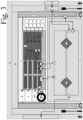
- Fig. 1 an exemplary overview is illustrated of how a safety system according to an embodiment of the invention is expected to work.
- the system can be applied on vehicles that contain some level of autonomy already. This is illustrated in the depicted vehicle that contains at least one sensor (three are shown in the drawing) and the main drive control unit, which already exists within most vehicles that contain ADAC systems.
- Data interfaces with the CECU to send vehicle driving data are depicted in the arrow leaving the vehicle from the antenna which depicted as the data interface with the CECU.
- the vehicle driving data compromising the vehicle sensory driving data and drive decision data generated by the main vehicle control unit.
- the vehicle sensory data includes information about at least one of a destination, remaining distance, route choice, and information from its sensors including the GPS position of the vehicle depicted also on the drawing in the centre of the vehicle.
- the at least one connected vehicle also receives PDD and CDD from the CECU.
- the PDD comprises the processed driving data which is compiled from the environmental sensors data and other vehicles driving data.
- the CDD comprises the CECU drive decision. This is depicted with microwaves leaving the building (e) where the CECU is located. The vehicle would receive the PDD and CECU with the depicted antenna.
- Examples of the endless possibilities of objects that can be seen in the environment are depicted, as well as major component of the safety system which is the environmental sensor, which in this example located in the streetlamps is illustrated as (c).
- the at least one sensor (c) connected to the CECU via the hardwired connection of the streetlamp to the main "building” is illustrated with (a), where the environmental data will be transferred as depicted in (d).
- the environmental data includes at least one of the environmental sensor's own location (illustrated with the GPS symbol on the drawing, surrounding environment data, which includes at least one , preferably both of fixed and time changing data from and around the road on a continuous basis, wherein the surrounding environment data preferably includes real time environment data surrounding the respective environmental sensor including at least one of the moving object's size, shape, movement speed and movement direction.
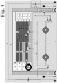
- Fig. 2 illustrates a first example embodiment of the invention, particularly the interrelationships between the components of the system, including the central data processing unit (CECU), the roadside components and the components in a vehicle that is connected to the system.
- CECU central data processing unit
- Fig. 2 illustrates a first example embodiment of the invention, particularly the interrelationships between the components of the system, including the central data processing unit (CECU), the roadside components and the components in a vehicle that is connected to the system.
- CECU central data processing unit
- Fig. 2 shows the following objects:
- Fug. 2 also shows the following interfaces for data communication:
- Fig. 3 shows the following objects:
- Fig. 3 also shows the following interfaces:
- Fig. 4 illustrates a third example embodiment of the invention different to those of Fig. 2 and Fig. 3 described above.
- Fig. 4 contains the following objects:
- Fig. 4 also shows the following interfaces:
Landscapes
- Physics & Mathematics (AREA)
- General Physics & Mathematics (AREA)
- Chemical & Material Sciences (AREA)
- Analytical Chemistry (AREA)
- Life Sciences & Earth Sciences (AREA)
- Atmospheric Sciences (AREA)
- Traffic Control Systems (AREA)
Claims (15)
- System zur Überwachung mindestens eines Fahrvorgangs mindestens eines Fahrzeugs, das sich entlang einer Fahrtroute in einem Betriebsbereich des Systems bewegt, wobei das System eine zentrale Datenverarbeitungs- und Steuereinheit (CECU), eine Vielzahl von Umweltsensoren (D, E), die an einer jeweiligen Vielzahl von festen Orten angeordnet sind, die in dem Betriebsbereich mindestens entlang der Fahrtroute verteilt sind, und eine Fahrzeugsteuereinheit (VECU) umfasst, die in dem mindestens einen Fahrzeug vorgesehen ist;wobei das mindestens eine Fahrzeug eine Hauptfahrzeugsteuereinheit (N) umfasst, die so konfiguriert ist, dass sie mindestens einen Fahrbetrieb des Fahrzeugs auf der Grundlage von Fahrzeugsensorik-Fahrdaten, die von mindestens einem Sensor des Fahrzeugs (J) während der Fahrt entlang der Fahrtroute erhalten werden, automatisiert steuert, wobei die Hauptfahrzeugsteuereinheit (N) so konfiguriert ist, dass sie Fahrzeugfahrdaten (VDD) sendet, die von der CECU empfangen werden sollen, wobei die Fahrzeugfahrdaten die Fahrzeugsensorik-Fahrdaten und Fahrentscheidungsdaten umfassen, die von der Hauptfahrzeugsteuereinheit (N) erzeugt werden, und dass sie verarbeitete Fahrdaten (PDD) empfängt, die von der CECU gesendet werden;wobei jeder der Umgebungssensoren (D, E) so konfiguriert ist, dass er Echtzeit-Umgebungsdaten für seinen jeweiligen festen Standort entlang der Reiseroute erfasst, wobei die Echtzeit-Umgebungsdaten Umgebungsdaten auf einer kontinuierlichen Basis umfassen, und wobei jeder der Umgebungssensoren (D, E) in Datenverbindung mit der CECU steht und so konfiguriert ist, dass er die Umgebungsdaten über die Datenverbindung an die CECU sendet;wobei die CECU entfernt von der Mehrzahl von Umweltsensoren (D, E) und entfernt von dem mindestens einen Fahrzeug angeordnet ist und umfasst:- eine erste CECU-Datenschnittstelle (1, 2), die so konfiguriert ist, dass sie die Umgebungsdaten über die Datenverbindung von der Mehrzahl der Umgebungssensoren (D, E) empfängt;- eine zweite CECU-Datenschnittstelle (3), die so konfiguriert ist, dass sie die vom Hauptfahrzeugsteuereinheit (N) des mindestens einen Fahrzeugs gesendeten Fahrzeugfahrdaten empfängt; und- eine dritte CECU-Datenschnittstelle (5), die so konfiguriert ist, dass sie verarbeitete Fahrdaten (PDD) sendet, die von der Hauptfahrzeugsteuereinheit (N) des mindestens einen Fahrzeugs empfangen werden;wobei die CECU so konfiguriert ist, dass sie die empfangenen Daten, einschließlich der Umgebungsdaten und der Fahrzeugfahrdaten, verarbeitet, um die verarbeiteten Fahrdaten (PDD) und eine CECU-Fahrentscheidung (CDD) zu erhalten, wobei die CECU ferner so konfiguriert ist, dass sie die von der Hauptfahrzeugsteuereinheit (N) des mindestens einen Fahrzeugs empfangene Fahrentscheidung mit der erhaltenen CDD vergleicht, und, falls der Vergleich keinen Konflikt verursacht, eine Bestätigung der Fahrentscheidung erhält, oder, für den Fall, dass der Vergleich einen Konflikt verursacht, ein Notfallsteuersignals zu erzeugen und das Notfallsteuersignals an die VECU zu senden, um die VECU zu veranlassen, eine Notfallaktion einzuleiten, um eine potenziell gefährliche Situation zu verhindern, wobei die VECU in direkter Datenverbindung mit der CECU steht, um das Notfallsteuersignals direkt von der CECU zu empfangen, und in weiterer Datenverbindung mit mindestens einem Antriebssteuersystem des Fahrzeugs steht, um das Antriebssteuersystem zu veranlassen, die Notfallaktion durchzuführen,dadurch gekennzeichnet, dassdie VECU als unabhängiges Bauteil in Bezug auf das Hauptfahrzeugsteuereinheit (N) konfiguriert ist, so dass das von der CECU gesendete Notfallsteuersignals direkt von der VECU empfangen werden kann, die die Notfallaktion einleitet, um eine potenziell gefährliche Situation zu verhindern, die von dem Hauptfahrzeugsteuereinheit (N) nicht gesehen oder nicht erkannt wurde, oder um unsichere Aktionen zu vermeiden, die das Hauptfahrzeugsteuereinheit (N) durchzuführen beabsichtigtund wobeidie VECU so konfiguriert ist, dass sie der Notfallaktion eine höhere Priorität einräumt als das Hauptfahrzeugsteuereinheit (N).
- Das System nach Anspruch 1, wobei das Antriebssteuersystem, das in Datenverbindung mit der VECU steht, ein Bremssystem des Fahrzeugs ist, und wobei das Notfallsteuersignals ein Bremssteuersignal ist, das die VECU veranlasst, das Bremssystem des Fahrzeugs als Notfallaktion zu aktivieren.
- Das System nach Anspruch 1 oder 2, wobei das Hauptfahrzeugsteuereinheit (N) des Fahrzeugs in Datenverbindung mit der VECU des Fahrzeugs steht, so dass eine Datenverbindung zwischen dem Hauptfahrzeugsteuereinheit (N) und der CECU über die VECU bereitgestellt wird, wobei die VECU so konfiguriert ist, dass sie die Fahrzeugfahrdaten von der Hauptfahrzeugsteuereinheit (N) über die Datenverbindung empfängt und die Fahrzeugfahrdaten an die CECU weiterleitet, wobei die VECU ferner so konfiguriert ist, dass sie die PDD von der CECU über die Datenverbindung empfängt und die PDD an die Hauptfahrzeugsteuereinheit (N) weiterleitet.
- Das System nach Anspruch 1 oder 2, wobei das Hauptfahrzeugsteuereinheit (N) des Fahrzeugs in Datenverbindung mit der CECU steht, so dass die Datenverbindung zwischen dem Hauptfahrzeugsteuereinheit (N) und der CECU in direkter Weise bereitgestellt wird, wobei das Hauptfahrzeugsteuereinheit (N) so konfiguriert ist, dass es die Fahrzeugfahrdaten über die Datenverbindung direkt an die CECU sendet und ferner die PDD von der CECU über die Datenverbindung direkt empfängt.
- Das System nach einem der vorhergehenden Ansprüche, wobei das System so konfiguriert ist, dass es mit dem Fahrzeug kommuniziert, um im Falle einer potenziellen Sicherheitsverletzung und/oder eines Sicherheitsrisikos eine Anhalteaufforderung zu senden, und wobei das System für den Fall, dass die Anhalteaufforderung nicht ausgeführt wird, so konfiguriert ist, dass es die Bremsen über die redundante Kanal-VECU aktiviert.
- Das System nach einem der vorhergehenden Ansprüche, wobei die VECU eine Antriebssteuereinheit des Fahrzeugs ist, wobei die Antriebssteuereinheit so konfiguriert ist, dass sie ein Antriebssteuersignal von der Hauptfahrzeugsteuereinheit empfängt, um mindestens einen Fahrbetrieb des mindestens einen Fahrzeugs zu steuern und/oder wobei die CECU so konfiguriert ist, dass sie das Notfallsteuersignals auch für den Fall erzeugt, dass das Hauptfahrzeugsteuereinheit des mindestens einen Fahrzeugs nicht in der Lage ist, die CDD zu empfangen oder nicht auf die CDD reagiert.
- Das System nach einem der vorhergehenden Ansprüche, wobei die Fahrzeugfahrdaten ferner Fahrplandaten umfassen, die Informationen über mindestens eines von einem Ziel, einer verbleibenden Entfernung und einer Routenwahl enthalten, wobei die CECU so konfiguriert ist, dass sie das PDD auf der Grundlage der jeweiligen Fahrplandaten an die Hauptfahrzeugsteuereinheit (N) des mindestens einen Fahrzeugs sendet, um die Hauptfahrzeugsteuereinheit (N) bei der weiteren Verfeinerung und Modifizierung ihrer Fahrentscheidungsdaten zu unterstützen.
- Das System nach einem der vorhergehenden Ansprüche, wobei die Umgebungsdaten mindestens eine der folgenden Angaben enthalten: den eigenen Standort des Umgebungssensors (D, E), Umgebungsdaten, wobei die Umgebungsdaten mindestens eine der folgenden Angaben enthalten: feste und sich zeitlich ändernde Daten von und um die Umgebungssensoren (D, E) auf kontinuierlicher Basis, wobei die Umgebungsdaten Echtzeit-Umgebungsdaten enthalten, die den jeweiligen Umgebungssensor (D, E) umgeben, einschließlich mindestens einer der folgenden Angaben: Größe, Form, Bewegungsgeschwindigkeit, Bewegungsrichtung und GPS-Koordinaten eines bewegten Objekts.
- Das System nach einem der vorhergehenden Ansprüche, wobei die CECU eine vierte CECU-Datenschnittstelle umfasst, die so konfiguriert ist, dass sie mindestens eine hochauflösende digitale 3D-Lebenskarte, Wolkenpunkte und Bilddaten empfängt.
- Das System nach einem der vorhergehenden Ansprüche, wobei die CECU ferner so konfiguriert ist, dass sie alle empfangenen Daten in Echtzeit zusammenstellt und sie entsprechend ihren GPS-Koordinaten auf entsprechenden Standortkarten anordnet, und ferner die CDD in Bezug auf die von dem mindestens einen Fahrzeug empfangenen Fahrzeugfahrdaten erhält.
- Das System nach Anspruch 10, wobei die CECU ferner so konfiguriert ist, dass sie alle Daten entsprechend ihren GPS-Koordinaten auf mindestens eine entsprechende Standortkarte legt, um eine dreidimensionale Karte in Echtzeit zu erstellen.
- Das System nach einem der vorhergehenden Ansprüche, wobei die Datenverbindung zwischen den Umweltsensoren und der CECU eine drahtgebundene Datenverbindung, vorzugsweise eine Hochgeschwindigkeits-Internetkabelverbindung, oder eine drahtlose Datenverbindung ist.
- Verfahren zur Überwachung mindestens eines Fahrvorgangs mindestens eines Fahrzeugs, umfassend
Bereitstellen eines Systems zur Überwachung mindestens eines Fahrbetriebs mindestens eines Fahrzeugs, wobei das System eine zentrale Datenverarbeitungs- und Steuereinheit (CECU), eine Vielzahl von Umweltsensoren, die an jeweils einer Vielzahl von im Betriebsbereich zumindest entlang der Fahrtroute verteilten festen Standorten angeordnet sind, und eine Fahrzeugsteuereinheit (VECU), die in dem mindestens einen Fahrzeug vorgesehen ist, umfasst;wobei das mindestens eine Fahrzeug eine Hauptfahrzeugsteuereinheit (N) umfasst, die automatisch mindestens einen Fahrvorgang des Fahrzeugs auf der Grundlage von Fahrzeugsensorik-Fahrdaten steuert, die von mindestens einem Sensor des Fahrzeugs (J) erhalten werden, wobei das Verfahren das Senden von Fahrzeugfahrdaten, die von der CECU empfangen werden sollen, mittels der Hauptfahrzeugsteuereinheit umfasst, wobei die Fahrzeugfahrdaten die Fahrzeugsensorik-Fahrdaten und Fahrentscheidungsdaten umfassen, die von der Hauptfahrzeugsteuereinheit erzeugt werden, und das Empfangen von verarbeiteten Fahrdaten (PDD), die von der CECU gesendet werden, mittels der Hauptfahrzeugsteuereinheit (N) umfasst;- Erfassen von Echtzeit-Umgebungsdaten für den jeweiligen festen Standort mit Hilfe der mehreren Umgebungssensoren (D, E), wobei die Echtzeit-Umgebungsdaten kontinuierlich Umgebungsdaten enthalten;- Senden der Umweltdaten mittels der mehreren Umweltsensoren (D, E) an die CECU, wobei die Umweltsensoren (D, E) jeweils in Datenverbindung mit der CECU stehen;- Empfangen der Umweltdaten über die Datenverbindung von den mehreren Umweltsensoren (D, E) durch die CECU an einer ersten CECU-Datenschnittstelle;- Empfangen der vom Hauptfahrzeugsteuereinheit des mindestens einen Fahrzeugs gesendeten Fahrzeugfahrdaten durch die CECU an einer zweiten CECU-Datenschnittstelle;- Senden von verarbeiteten Fahrdaten (PDD), die von der Hauptfahrzeugsteuereinheit des mindestens einen Fahrzeugs empfangen werden sollen, durch die CECU an einer dritten CECU-Datenschnittstelle;- Verarbeitung der empfangenen Daten, einschließlich der Umgebungsdaten und der Fahrdaten des Fahrzeugs, durch die CECU, um die verarbeiteten Fahrdaten (PDD) und eine CECU-Fahrentscheidung (CDD) zu erhalten;- Vergleichen, mittels der CECU, der Fahrentscheidung, die von der Hauptfahrzeugsteuereinheit des mindestens einen Fahrzeugs empfangen wurde, mit der erhaltenen CDD, und, falls der Vergleich keinen Konflikt verursacht, Erhalten einer Bestätigung der Fahrentscheidung, oder, falls der Vergleich einen Konflikt verursacht, Erzeugen, mittels der CECU, eines Notfallsteuersignals und Senden des Notfallsteuersignals an die VECU, um die VECU zu veranlassen, eine Notfallmaßnahme einzuleiten, um eine potenziell gefährliche Situation zu verhindern, wobei in diesem Fall das Verfahren ferner umfasst- direktes Empfangen des Notsteuersignals von der CECU mittels der VECU über eine direkte Datenverbindung mit der CECU, wobei die VECU in weiterer Datenverbindung zu mindestens einem Antriebssteuersystem des Fahrzeugs steht, um das Antriebssteuersystem zu veranlassen, die Notaktion durchzuführen unddadurch gekennzeichnet, dassdie VECU als unabhängige Komponente in Bezug auf das Hauptfahrzeugsteuereinheit (N) konfiguriert ist, so dass das von der CECU gesendete Notfallsteuersignals direkt von der VECU empfangen werden kann, die die Notfallaktion einleitet, um eine potenziell gefährliche Situation zu verhindern, die vom Hauptfahrzeugsteuereinheit (N) nicht gesehen oder nicht erkannt wird, oder um unsichere Aktionen zu vermeiden, die das Hauptfahrzeugsteuereinheit (N) zu unternehmen beabsichtigtund wobeidie VECU so konfiguriert ist, dass sie der Notfallaktion eine höhere Priorität einräumt als das Hauptfahrzeugsteuereinheit (N). - Verfahren nach Anspruch 13, bei dem die VECU eine Antriebssteuereinheit ist, wobei das Verfahren ferner umfasst:- Empfangen eines Fahrsteuersignals von der Hauptfahrzeugsteuereinheit durch die Antriebssteuereinheit, um mindestens einen Fahrvorgang des mindestens einen Fahrzeugs zu steuern, oder- Empfang des Notfallsteuersignals von der CECU durch die Antriebssteuereinheit, um die Notmaßnahme als Fahrvorgang durchzuführen;wobei das System so konfiguriert ist, dass es mit dem Fahrzeug kommuniziert, um im Falle einer potenziellen Sicherheitsverletzung und/oder eines Sicherheitsrisikos eine Anhalteaufforderung zu senden, und wobei das System, falls die Anhalteaufforderung nicht ausgeführt wird, so konfiguriert ist, dass es die Bremsen über den redundanten Kanal VECU aktiviert.
- Verwendung des Systems nach einem der Ansprüche 1 bis 12 zur Vermeidung einer potenziell gefährlichen Situation, z.B. eines Zusammenstoßes mit einem sich bewegenden und/oder nicht bewegenden Objekt, indem sichergestellt wird, dass ein sicherer Zustand des Fahrzeugs erreicht wird.
Priority Applications (2)
| Application Number | Priority Date | Filing Date | Title |
|---|---|---|---|
| ES21020467T ES2994871T3 (en) | 2021-09-17 | 2021-09-17 | A system for monitoring a driving operation of a vehicle |
| EP21020467.3A EP4152293B1 (de) | 2021-09-17 | 2021-09-17 | System zur überwachung des fahrbetriebs eines fahrzeugs |
Applications Claiming Priority (1)
| Application Number | Priority Date | Filing Date | Title |
|---|---|---|---|
| EP21020467.3A EP4152293B1 (de) | 2021-09-17 | 2021-09-17 | System zur überwachung des fahrbetriebs eines fahrzeugs |
Publications (3)
| Publication Number | Publication Date |
|---|---|
| EP4152293A1 EP4152293A1 (de) | 2023-03-22 |
| EP4152293C0 EP4152293C0 (de) | 2024-11-20 |
| EP4152293B1 true EP4152293B1 (de) | 2024-11-20 |
Family
ID=77838661
Family Applications (1)
| Application Number | Title | Priority Date | Filing Date |
|---|---|---|---|
| EP21020467.3A Active EP4152293B1 (de) | 2021-09-17 | 2021-09-17 | System zur überwachung des fahrbetriebs eines fahrzeugs |
Country Status (2)
| Country | Link |
|---|---|
| EP (1) | EP4152293B1 (de) |
| ES (1) | ES2994871T3 (de) |
Citations (2)
| Publication number | Priority date | Publication date | Assignee | Title |
|---|---|---|---|---|
| US20160284212A1 (en) * | 2015-03-28 | 2016-09-29 | Igor Tatourian | Technologies for detection of anomalies in vehicle traffic patterns |
| US20190392712A1 (en) * | 2018-06-20 | 2019-12-26 | Cavh Llc | Connected automated vehicle highway systems and methods related to heavy vehicles |
Family Cites Families (3)
| Publication number | Priority date | Publication date | Assignee | Title |
|---|---|---|---|---|
| US20170327035A1 (en) * | 2016-05-10 | 2017-11-16 | Ford Global Technologies, Llc | Methods and systems for beyond-the-horizon threat indication for vehicles |
| US10235882B1 (en) * | 2018-03-19 | 2019-03-19 | Derq Inc. | Early warning and collision avoidance |
| US11170639B2 (en) * | 2019-03-05 | 2021-11-09 | University Of Massachusetts | Transportation threat detection system |
-
2021
- 2021-09-17 EP EP21020467.3A patent/EP4152293B1/de active Active
- 2021-09-17 ES ES21020467T patent/ES2994871T3/es active Active
Patent Citations (2)
| Publication number | Priority date | Publication date | Assignee | Title |
|---|---|---|---|---|
| US20160284212A1 (en) * | 2015-03-28 | 2016-09-29 | Igor Tatourian | Technologies for detection of anomalies in vehicle traffic patterns |
| US20190392712A1 (en) * | 2018-06-20 | 2019-12-26 | Cavh Llc | Connected automated vehicle highway systems and methods related to heavy vehicles |
Also Published As
| Publication number | Publication date |
|---|---|
| EP4152293A1 (de) | 2023-03-22 |
| EP4152293C0 (de) | 2024-11-20 |
| ES2994871T3 (en) | 2025-02-03 |
Similar Documents
| Publication | Publication Date | Title |
|---|---|---|
| US20250150792A1 (en) | Vehicle-based cloud computing system for autonomous driving | |
| US12524002B2 (en) | Systems and methods for centralized control of autonomous vehicles | |
| Dokic et al. | European roadmap smart systems for automated driving | |
| US11215984B2 (en) | Systems and methods for controlling an autonomous vehicle | |
| US8954205B2 (en) | System and method for road side equipment of interest selection for active safety applications | |
| Mueck et al. | Networking vehicles to everything: Evolving automotive solutions | |
| US8892347B1 (en) | System and method for node adaptive filtering and congestion control for safety and mobility applications toward automated vehicles system | |
| Englund et al. | Future applications of VANETs | |
| DE102021131848A1 (de) | Sicherheits-gateway | |
| Schwarz et al. | Towards autonomous vehicles | |
| Daddanala et al. | Vehicle to vehicle (V2V) Communication Protocol: components, benefits, challenges, safety and machine learning applications | |
| Hamid | Autonomous, connected, electric and shared vehicles: Disrupting the automotive and mobility sectors | |
| Rahman et al. | Transportation policies for connected and automated mobility in smart cities | |
| Noh et al. | Toward highly automated driving by vehicle-to-infrastructure communications | |
| EP4152293B1 (de) | System zur überwachung des fahrbetriebs eines fahrzeugs | |
| Beiker | Unsettled issues in remote operation for on-road driving automation | |
| Alessandrini et al. | ARTS—automated roadtransport systems | |
| Rai et al. | Security Challenges of IoT-Enabled Vehicular Communications and Their Countermeasures | |
| Luu et al. | Digital Infrastructure for Connected and Automated Vehicles | |
| Nakanishi et al. | Connected vehicles and driving automation systems | |
| Goel et al. | Emerging Research in Connected Vehicles [Guest Editorial] | |
| Force | Automated Driving Roadmap | |
| Swami et al. | The role of 5g in smart transportation | |
| Singh et al. | Internet of vehicles: a study | |
| Jacobson et al. | Functional Safety in Systems of Road Vehicles |
Legal Events
| Date | Code | Title | Description |
|---|---|---|---|
| PUAI | Public reference made under article 153(3) epc to a published international application that has entered the european phase |
Free format text: ORIGINAL CODE: 0009012 |
|
| STAA | Information on the status of an ep patent application or granted ep patent |
Free format text: STATUS: REQUEST FOR EXAMINATION WAS MADE |
|
| 17P | Request for examination filed |
Effective date: 20230208 |
|
| AK | Designated contracting states |
Kind code of ref document: A1 Designated state(s): AL AT BE BG CH CY CZ DE DK EE ES FI FR GB GR HR HU IE IS IT LI LT LU LV MC MK MT NL NO PL PT RO RS SE SI SK SM TR |
|
| STAA | Information on the status of an ep patent application or granted ep patent |
Free format text: STATUS: EXAMINATION IS IN PROGRESS |
|
| 17Q | First examination report despatched |
Effective date: 20230523 |
|
| GRAP | Despatch of communication of intention to grant a patent |
Free format text: ORIGINAL CODE: EPIDOSNIGR1 |
|
| STAA | Information on the status of an ep patent application or granted ep patent |
Free format text: STATUS: GRANT OF PATENT IS INTENDED |
|
| INTG | Intention to grant announced |
Effective date: 20240104 |
|
| GRAJ | Information related to disapproval of communication of intention to grant by the applicant or resumption of examination proceedings by the epo deleted |
Free format text: ORIGINAL CODE: EPIDOSDIGR1 |
|
| STAA | Information on the status of an ep patent application or granted ep patent |
Free format text: STATUS: EXAMINATION IS IN PROGRESS |
|
| INTC | Intention to grant announced (deleted) | ||
| GRAP | Despatch of communication of intention to grant a patent |
Free format text: ORIGINAL CODE: EPIDOSNIGR1 |
|
| STAA | Information on the status of an ep patent application or granted ep patent |
Free format text: STATUS: GRANT OF PATENT IS INTENDED |
|
| INTG | Intention to grant announced |
Effective date: 20240619 |
|
| GRAS | Grant fee paid |
Free format text: ORIGINAL CODE: EPIDOSNIGR3 |
|
| GRAA | (expected) grant |
Free format text: ORIGINAL CODE: 0009210 |
|
| STAA | Information on the status of an ep patent application or granted ep patent |
Free format text: STATUS: THE PATENT HAS BEEN GRANTED |
|
| AK | Designated contracting states |
Kind code of ref document: B1 Designated state(s): AL AT BE BG CH CY CZ DE DK EE ES FI FR GB GR HR HU IE IS IT LI LT LU LV MC MK MT NL NO PL PT RO RS SE SI SK SM TR |
|
| REG | Reference to a national code |
Ref country code: GB Ref legal event code: FG4D |
|
| REG | Reference to a national code |
Ref country code: CH Ref legal event code: EP |
|
| REG | Reference to a national code |
Ref country code: DE Ref legal event code: R096 Ref document number: 602021021939 Country of ref document: DE |
|
| REG | Reference to a national code |
Ref country code: IE Ref legal event code: FG4D |
|
| U01 | Request for unitary effect filed |
Effective date: 20241211 |
|
| U07 | Unitary effect registered |
Designated state(s): AT BE BG DE DK EE FI FR IT LT LU LV MT NL PT RO SE SI Effective date: 20241220 |
|
| REG | Reference to a national code |
Ref country code: ES Ref legal event code: FG2A Ref document number: 2994871 Country of ref document: ES Kind code of ref document: T3 Effective date: 20250203 |
|
| PG25 | Lapsed in a contracting state [announced via postgrant information from national office to epo] |
Ref country code: IS Free format text: LAPSE BECAUSE OF FAILURE TO SUBMIT A TRANSLATION OF THE DESCRIPTION OR TO PAY THE FEE WITHIN THE PRESCRIBED TIME-LIMIT Effective date: 20250320 Ref country code: HR Free format text: LAPSE BECAUSE OF FAILURE TO SUBMIT A TRANSLATION OF THE DESCRIPTION OR TO PAY THE FEE WITHIN THE PRESCRIBED TIME-LIMIT Effective date: 20241120 |
|
| PG25 | Lapsed in a contracting state [announced via postgrant information from national office to epo] |
Ref country code: NO Free format text: LAPSE BECAUSE OF FAILURE TO SUBMIT A TRANSLATION OF THE DESCRIPTION OR TO PAY THE FEE WITHIN THE PRESCRIBED TIME-LIMIT Effective date: 20250220 |
|
| PG25 | Lapsed in a contracting state [announced via postgrant information from national office to epo] |
Ref country code: GR Free format text: LAPSE BECAUSE OF FAILURE TO SUBMIT A TRANSLATION OF THE DESCRIPTION OR TO PAY THE FEE WITHIN THE PRESCRIBED TIME-LIMIT Effective date: 20250221 |
|
| PG25 | Lapsed in a contracting state [announced via postgrant information from national office to epo] |
Ref country code: PL Free format text: LAPSE BECAUSE OF FAILURE TO SUBMIT A TRANSLATION OF THE DESCRIPTION OR TO PAY THE FEE WITHIN THE PRESCRIBED TIME-LIMIT Effective date: 20241120 |
|
| PG25 | Lapsed in a contracting state [announced via postgrant information from national office to epo] |
Ref country code: RS Free format text: LAPSE BECAUSE OF FAILURE TO SUBMIT A TRANSLATION OF THE DESCRIPTION OR TO PAY THE FEE WITHIN THE PRESCRIBED TIME-LIMIT Effective date: 20250220 |
|
| PG25 | Lapsed in a contracting state [announced via postgrant information from national office to epo] |
Ref country code: SM Free format text: LAPSE BECAUSE OF FAILURE TO SUBMIT A TRANSLATION OF THE DESCRIPTION OR TO PAY THE FEE WITHIN THE PRESCRIBED TIME-LIMIT Effective date: 20241120 |
|
| PG25 | Lapsed in a contracting state [announced via postgrant information from national office to epo] |
Ref country code: SK Free format text: LAPSE BECAUSE OF FAILURE TO SUBMIT A TRANSLATION OF THE DESCRIPTION OR TO PAY THE FEE WITHIN THE PRESCRIBED TIME-LIMIT Effective date: 20241120 |
|
| PG25 | Lapsed in a contracting state [announced via postgrant information from national office to epo] |
Ref country code: CZ Free format text: LAPSE BECAUSE OF FAILURE TO SUBMIT A TRANSLATION OF THE DESCRIPTION OR TO PAY THE FEE WITHIN THE PRESCRIBED TIME-LIMIT Effective date: 20241120 |
|
| PLBE | No opposition filed within time limit |
Free format text: ORIGINAL CODE: 0009261 |
|
| STAA | Information on the status of an ep patent application or granted ep patent |
Free format text: STATUS: NO OPPOSITION FILED WITHIN TIME LIMIT |
|
| PGFP | Annual fee paid to national office [announced via postgrant information from national office to epo] |
Ref country code: GB Payment date: 20250923 Year of fee payment: 5 |
|
| 26N | No opposition filed |
Effective date: 20250821 |
|
| U20 | Renewal fee for the european patent with unitary effect paid |
Year of fee payment: 5 Effective date: 20250922 |
|
| PGFP | Annual fee paid to national office [announced via postgrant information from national office to epo] |
Ref country code: ES Payment date: 20251020 Year of fee payment: 5 |
|
| REG | Reference to a national code |
Ref country code: CH Ref legal event code: H13 Free format text: ST27 STATUS EVENT CODE: U-0-0-H10-H13 (AS PROVIDED BY THE NATIONAL OFFICE) Effective date: 20260425 |