EP4152223B1 - Verfahren und systeme zur authentifizierung einer hf-vorrichtung - Google Patents
Verfahren und systeme zur authentifizierung einer hf-vorrichtung Download PDFInfo
- Publication number
- EP4152223B1 EP4152223B1 EP21197936.4A EP21197936A EP4152223B1 EP 4152223 B1 EP4152223 B1 EP 4152223B1 EP 21197936 A EP21197936 A EP 21197936A EP 4152223 B1 EP4152223 B1 EP 4152223B1
- Authority
- EP
- European Patent Office
- Prior art keywords
- model
- feature data
- data
- signal
- steps
- Prior art date
- Legal status (The legal status is an assumption and is not a legal conclusion. Google has not performed a legal analysis and makes no representation as to the accuracy of the status listed.)
- Active
Links
Images

Classifications
-
- H—ELECTRICITY
- H04—ELECTRIC COMMUNICATION TECHNIQUE
- H04W—WIRELESS COMMUNICATION NETWORKS
- H04W12/00—Security arrangements; Authentication; Protecting privacy or anonymity
- H04W12/06—Authentication
-
- H—ELECTRICITY
- H04—ELECTRIC COMMUNICATION TECHNIQUE
- H04W—WIRELESS COMMUNICATION NETWORKS
- H04W12/00—Security arrangements; Authentication; Protecting privacy or anonymity
- H04W12/60—Context-dependent security
- H04W12/69—Identity-dependent
- H04W12/79—Radio fingerprint
-
- G—PHYSICS
- G06—COMPUTING OR CALCULATING; COUNTING
- G06N—COMPUTING ARRANGEMENTS BASED ON SPECIFIC COMPUTATIONAL MODELS
- G06N20/00—Machine learning
Definitions
- the devices can communicate using the radio spectrum, from cell phones to IoT sensors/devices.
- the devices carry an ID (in other words: an identifier) and implement some security measures such as encryption, identification and/or authentication to ensure confidentiality and/or authenticity of the RF communications.
- the devices are often low cost and based on hardware with a low level of security. Generally, they have an ID but the hardware security is not robust.
- Authentication is a key act to build a communication system of trusted devices.
- a RF device To communicate by radio, a RF device has a chain of analog components, such as an oscillator, inductor, capacitor, ....
- the analog components are not perfect, and these imperfections have an impact on the form of the electromagnetic spectrum sent by the RF device via radio waves.
- the carrier frequency can have an offset due to a non-perfect oscillator.
- Such imperfection (Carrier Frequency Offset or "CFO") has no effect on the operation of the RF device, but it can be observed in its transmission spectrum. It creates a fingerprint of the RF device within the RF transmissions of the RF device. Since the hardware imperfections are almost impossible to clone, resulting fingerprints can be used to identify and/or authenticate the RF transmitter device. It is known to use such a fingerprint to identify and/or authenticate the RF transmitter device.
- CFO Carrier Frequency Offset
- US 10,693,576 B2 discloses a method of fingerprinting authentication to authenticate a RF device based on CFO (Carrier Frequency Offset), used as a RF fingerprint of the RF device, and operational and/or ambient conditions such as temperature, relative humidity, etc... More precisely, CFO values of the RF transmissions originating from the RF device are calculated and used as a RF fingerprint of the RF device. Indeed, small imperfections in the analog components of the RF device induce small variations in its RF transmissions.
- the method disclosed in US 10,693,576 B2 includes the following steps:
- the present disclosure concerns a computer-implemented method for authentication of a first device, comprising the following steps:
- the feature data of the received RF signals includes I or Q data (in other words: I data or Q data).
- I or Q data in other words: I data or Q data.
- the model is stored in the second RF device.
- the second RF device is paired with the first RF device.
- the two paired RF devices are expected to communicate with each other.
- the first RF device is an IoT device or sensor and the second device is an IoT gateway.
- the first RF device wants to connect to and/or communicate with the second RF device, the latter performs the steps E) to G) above defined in order to allow (or not to allow) the first RF device access to the second RF device and/or further online services.
- the above defined method for authenticating the first RF device based on RF signals transmitted by said first RF device facilitates the authentication, improves its performance and reduces the computational efforts.
- the authentication is based on the I data or Q data obtained from the RF signal received from the first RF device, which facilitates the implementation of the method.
- the I data or Q data are used as a fingerprint of the first RF device.
- the authentication is very accurate. There is no need to use the ambient and/or operational conditions to authenticate in a reliable and efficient manner.
- the present method allows to have a good authentication scheme, while reducing production cost and computational efforts.
- the feature data includes values of only one of the in-phase component I(t) and the quadrature component Q(t) of the received RF signal the amount of data is reduced.
- the model can be a machine learning model, and the step of fitting the model can include a step of training the machine learning model using the feature data as input training data.
- the model is an anomaly detection model.
- anomaly detection also termed as outlier detection
- outlier detection is the identification of rare items, events or observations which raise suspicions by differing significantly from most of the data.
- the anomaly detection is very well adapted to the problem. It allows to flag a new incoming RF signal, converted into feature data, as an anomaly or a normal RF signal.
- the anomaly detection allows to detect if a new incoming RF signal is a normal RF signal, sent from the genuine RF device, or an anomaly (sent by a cloned RF device).
- the model After storing of the fitted model in memory, the model can be updated by the second device based on feature data acquired from a new RF signal received from the first device. Thus, after storage in memory in the second RF device, the fitted model can be updated with new feature data from RF signal(s) newly received from the first RF device. This allows to adapt the model to various environmental conditions that may not be included in the initial model stored in memory in the second RF device.
- the method further comprises a step of normalizing the feature data (in other words: the I data or Q data) before providing the normalized feature data to the model in at least one of the steps C) and G).
- the main advantage of the data normalization is to make the data less dependent on the signal's strength received by the second RF device. Indeed, the strength of the received signal has an impact on the absolute values of the feature data: the smaller the received signal strength, the closer the received feature values are to 0. By forcing all values to be in the same scale through normalization, the model becomes less sensitive to the received signal strength.
- the method further comprises a step of filtering the feature data before providing the filtered feature data to the model in at least one of the steps C) and G).
- Some received RF signals may require to be processed or removed.
- the duration of a RF signal can be abnormally very short compared to the average duration of the RF signals.
- the actions of removing or processing RF signals allows to improve the efficiency and accuracy of the method.
- decimation can be performed. It basically consists in removing samples (and usually also applying a low-pass filter). The goal is to have less samples to process.
- the set of steps A) to C) can performed by the second device or, alternatively, by a third device, different from the second device.
- the steps A) to C) are also performed for a plurality of RF signals transmitted by the second device to fit a model for authenticating said second device, and the steps D) to G) are also performed by the first device for authentication of the second device using said fitted model, so that the first and second devices perform a mutual authentication.
- the steps A) to C) are performed for a plurality of first devices and a plurality of fitted models, corresponding to the plurality of first devices respectively, are stored in memory in the second device.
- the method can further comprise
- the present disclosure also concerns a system for authentication of a first device, comprising
- the present disclosure also concerns a computer program comprising instructions which, when the program is executed by a computer, cause the computer to perform the steps of the computer-implemented method previously defined.
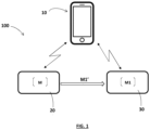
- the computer-implemented method of the present disclosure may be used to identify and/or authenticate a wireless, or RF (Radio Frequency), first device 10.
- the authentication of the first RF device 10 is based on RF signals transmitted by said first RF device 10, more precisely on feature data of the RF signals from the first RF device 10.
- the computer-implemented method includes an initial phase (process) for fitting (or training) a model for authentication of the first device 10 and an operational phase wherein the fitted model is used by a second RF device 30 to authenticate the first device 10.
- the initial phase can be performed by the second RF device 30 or, alternatively, by a third RF device 20, different from the second RF device 30.
- the first RF device 10 can be a RF transmitter device or a RF transceiver device.
- the second RF device 30 can be a receiver device or a transceiver device.
- the third RF device 20 can be a receiver device or a transceiver device.
- the first RF device 10 and the second RF device 30 are paired or to be paired with each other.
- the first RF device 10 is an IoT device or sensor and the second RF device 30 is an IoT gateway.
- the RF signals transmitted by the first RF device 10 are a repetition of a same message, with the same content and the same device and/or protocol specific parameters. In that case, the RF device 10 sends repeatedly the same message. It can be a message intended to be sent later by the RF device 10 in operational mode (in other words: during use of the RF device 10 in real environment). In another embodiment, different messages could be sent.
- the RF device 10 is intended to send different messages during its life-time (in operational mode), these messages can be used to efficiently train the model. More precisely, feature data acquired from the received RF signals SGi(t) is then used to fit (in other words: to learn, or train) a model M responsible for performing (later) a task of authenticating the first RF device 10.
- the number of sent messages necessary to obtain a performant model for authentication may depend on the first device 10, the content of the message, and/or other parameters. For instance, several hundred messages could be sent to correctly fit the model M on the first RF device 10.
- the model M is saved and the second RF device 30 stores it in memory. Then, in an operational mode (in other words: at an inference stage), the second RF device 30 can authenticate the first (known) RF device 10 by transmitting (giving) as input to the model M stored in memory, one or more new RF signals transmitted from the first RF device 10 to the second RF device 30.
- the feature data acquired from any RF signal includes I data and Q data of the RF signal over time, in other words a series of values of the in-phase component I(t) and a series of values of a quadrature component Q(t), of the received RF signal SGi(t) over time.
- the I data and Q data are acquired from the received RF signal SGi(t) over time by a component of a radio receiver and/or by a quadrature demodulator (also termed as an I/Q demodulator), of the second device 30 or third device 20.
- the feature data acquired from a received RF signal (or message) and to be provided to the model M (in initial phase) or M1 (in operational mode) includes either only the I data (in other words only a series of values of the in-phase component I(t) of the received RF signal over time), or only the Q data (in other words only a series of values of the quadrature-phase component Q(t) of the received RF signal over time).
- the feature data acquired from any RF signal originating from a RF device is used as a fingerprint of said RF device.
- the model is an Anomaly Detection model.
- Anomaly Detection also termed as “Outlier Detection”
- AD Anomaly Detection
- the goal is to detect if a new incoming message (in other words: a new received RF signal) is a normal message sent by a known transmitter device or an anomaly sent by another device, like a cloned device. So, an advantage of using specifically an Anomaly Detection model is for interpretability and good understanding of the strategy.
- the model M is a machine learning model. It is trained to authenticate the first RF device 10 using the feature data (in other words: the I data and Q data, or I data only, or Q data only) acquired from each of a plurality of RF signals received from the first RF device 10. Thus, the model M learns the specificities of the first RF device 10.
- the model M could be a statistical model, a spectral model or an information-theoretic based model.
- the second RF device 30 is responsible for authenticating the first RF device 10 using the stored model M1, previously fitted or trained.
- the second RF device 30 When the second RF device 30 receives a new RF signal from a RF device to authenticate T, it acquires the feature data from the received RF signal (in other words: the I data and Q data, or alternatively only the I or Q data) and transmits (provides) the acquired feature data as input data to the model M1 stored in memory to determine whether or not the RF device to authenticate T is the first RF device 10.
- the feature data in other words: the I data and Q data, or alternatively only the I or Q data
- the feature data (I data and Q data, or only I or Q data) can optionally be pre-processed before being provided as inputs to the model.
- the pre-processing can include a normalization and/or a filtering by removing and/or processing data, as explained later in more detail.
- the system 100 includes the second RF device 30 and optionally the third RF device 20.
- a role of the second RF device 30 (or, alternatively, of the third RF device 20) is to fit the model M to RF received signals transmitted by the first RF device 10.
- the second RF device 30 stores in memory the model M1 fitted to the first RF device 10. Then, the second RF device 30 can authenticate the first RF device 10 by means of the model M1 and using one or more RF signals transmitted from the first RF device 10 and provided as input to the model M1.
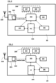
- the second RF device 30 illustrated in figure 2 includes an antenna 300, a radio receiver 301 with an IQ-demodulator 302, a processor or CPU (Central Processing Unit) 303, a RAM 304, a storage unit 305, a fitting or training component 306 to train (fit) a model and optionally update the fitted model, and an authentication component 310.
- a radio receiver 301 with an IQ-demodulator 302 includes a processor or CPU (Central Processing Unit) 303, a RAM 304, a storage unit 305, a fitting or training component 306 to train (fit) a model and optionally update the fitted model, and an authentication component 310.
- a processor or CPU Central Processing Unit
- the radio receiver 301 receives radio waves through the antenna 300 and converts the information carried by the radio waves to a usable form. It includes different components (mixers, filters, amplifiers, modulators/demodulators, detectors, etc.) that can be implemented in hardware and/or software.
- the radio receiver includes a software defined radio or SDR chip where components are implemented by software.
- the radio receiver could be implemented in hardware or by a mix of hardware and software.
- the second RF device 30 introduces low jitter (bias) in the received RF signals.
- the second RF device 30 is likely to introduce jitter or bias in the received RF signals since it is also dependent on analog components. This bias can be significantly reduced by using high quality components.
- the third RF device 20 is responsible for fitting (training) the model M to RF received signals transmitted by the first RF device 10 and the second RF device 30 then uses the fitted model.
- the bias introduced by the second RF device 30 doesn't matter. In that case (when the same receiver is used for training and operations), it is not necessary to use high quality components.
- the radio receiver 301 includes an IQ-demodulator 302 (also called a quadrature demodulator) responsible for converting RF input signals to two baseband signals, including an in-phase signal (component) I(t) and a quadrature signal (component) Q(t), that are converted to digital data by sampling.
- an IQ-demodulator 302 also called a quadrature demodulator
- the IQ-demodulator converts the RF input signal into 100 values of the I(t) component and 100 values of the Q(t) component.
- These values can be represented in form of a vector of complex numbers, for example [0.7+0.5j; 0.2+0.3j; ...].
- values produced by the IQ-demodulator are comprised within (-1.0, 1.0).
- the first sample is described as "0.7+0.5j", which means that the I value is "0.7” and the Q value is "0.5".
- the vector of complex numbers can be converted into two vectors that respectively contains the I values and the Q values.
- radio receiver 301 The other components of the radio receiver 301 are well known by the person skilled in the art and will not be described in further detail in the present disclosure.
- the storage unit (memory) 305 stores one or more models for authentication of one or more RF devices.
- the storage unit 305 stores a model M to be fitted (in other words: learned or trained) on RF signals originating from a first RF device.
- the storage unit 205 can also store one or more fitted (trained) models M1, M2, M3, ...
- a model could be fitted on a plurality of first RF devices (different RF devices).
- the second RF device 30 is responsible for recognizing a group of first RF devices (the first RF devices on which the model is fitted), and not only one first device.
- one model could be trained to recognize one particular first RF device 10.
- a plurality of different models are trained to recognize a plurality of first RF devices 10 (one model for each first RF device). Indeed, training several models (one for each first RF device) is better at rejecting cloned devices than fitting only one model.
- the CPU 303 controls the operation of the second RF device 30.
- the RAM 304 is the working memory of the CPU 303.
- the second RF device 30 has a processing component 309 including a normalization part 307 and/or a filtering part 308 (with one or more filters).
- the normalization part 307 is a software component that runs on the CPU 303. It is responsible for normalizing the feature data (in other words: the I data and Q data or, alternatively, only the I or Q data) acquired from the RF input signals received by the radio receiver 301.
- the normalization achieves to force all values to have a same scale. It can use a standardization technique. For example, a mean value is removed from each value and the result is divided by a standard deviation of the values to scale the values within the (-1.0; 1.0) range. For instance, if the received I values are between -0.1 and 0.6, the standardization converts to values in the range (-1.0; 1.0), with a mean of zero and a standard deviation of 1.
- the normalization can be applied separately for the I values and for the Q values.
- the I vector is [0.7 ; 0.2 ; ...] and the Q vector is [0.5 ; 0.3 ; ...]. Since the I and Q values may not be correlated, the respective distributions of the I values and Q values may not be the same. For example, the I values can be centered around 0.5 and the Q values around 0.7 for the 100 values obtained from the RF input signal of 1 second. Therefore, the I values and the Q values are processed as two independent (separate) vectors that must be normalized independently.
- the normalization mostly allows that the I values and Q values are insensible to the signal's strength acquired by the receiver (here the receiver device 20). For instance, the distance has an impact on the absolute range of the I and Q values: the greater the distance, the closer the received I and Q values are to 0. So, normalizing the I and Q vectors can render the model less sensitive to the strength of the received signal, by forcing all values to be in the same scale.
- the one or more filters, or filtering part, 308 is responsible for filtering the feature data (in other words: the I data and Q data or, alternatively, only the I or Q data) before providing said feature data to the training component 306.
- the filtering part 308 is a software component that runs on the CPU 303. Alternatively, it could be hardware (e.g., a band pass filter to isolate signals of interest and avoid interferences from other signals) or a mix of software and hardware. It is responsible for filtering the feature data acquired from the RF input signals received by the radio receiver 301 by processing or removing data. For example, some RF signals received by the second RF device 30 have an abnormal duration that is very short compared to the average duration of the RF signals. The data obtained from such very short RF signals could be removed.
- the filtering part 308 includes one or more of the following elements for processing the data: a noise blanker, a noise reducer, a band pass filter and an interference detector.
- the authentication component 310 is responsible for authenticating the first RF device 10 based on one or more RF signals originating from the first RF device 10, received by the radio receiver 301 and applied (in other words: provided as inputs) to the stored model M1, as will be described in more detail later.
- the system includes the third RF device 20, illustrated in figure 3 , responsible for performing the fitting or training process (instead of the second RF device 30).
- the third RF device 20 includes an antenna 200, a radio receiver 201, a processor or CPU (Central Processing Unit) 203, a RAM 204, a storage unit 205 and a fitting or training component 206.
- the third RF device 20 introduces low jitter (bias) in the received RF signals.
- the third RF device 20 is likely to introduce jitter or bias in the received RF signals since it is also dependent on analog components. This bias can be significantly reduced by using high quality components.
- the radio receiver 201 can include an IQ-demodulator 202 (also called a quadrature demodulator) responsible for converting RF input signals to two baseband signals, including an in-phase signal (component) I(t) and a quadrature signal (component) Q(t), that are converted to digital data by sampling.
- IQ-demodulator 202 also called a quadrature demodulator
- I(t) in-phase signal
- Q(t) quadrature signal
- the storage unit 205 stores one or more models to be fitted (in other words: adapted or trained) on RF signals originating from one or more first RF devices, for example the first RF device 10.
- the storage unit 205 stores the model M to be fitted on RF signals from the first RF device 10.
- the CPU 203 controls the operation of the third RF device 20.
- the RAM 204 is the working memory of the CPU 203.
- the training (fitting) component 206 is a software component that runs on the CPU 203 to fit or train a model (e.g., M1) stored in the storage unit 205 on RF input signals originating from a corresponding RF transmitter device (e.g., the first RF device 10).
- a model e.g., M1
- the third RF device 20 has a processing component 209 for pre-processing the feature data (in other words: the I data and Q data or, alternatively, only the I or Q data) before providing said feature data to the training component 206.
- a processing component 209 for pre-processing the feature data (in other words: the I data and Q data or, alternatively, only the I or Q data) before providing said feature data to the training component 206.
- It can include a normalization part 207 and/or a filtering part 208 with one or more filters.
- the normalization part 207 is similar to the normalization part 307.
- the filtering part 208 is similar to the filtering part 308.
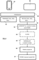
- Figure 4 illustrates an initial phase, or training process, of the computer-implemented method for authenticating the first RF device 10, described below.
- the initial phase allows to train the model M on RF signals sent from the first RF device 10.
- the initial phase is executed by the second RF device 30.
- the model M is a machine learning (ML) model. It is also an anomaly detection (AD) model.
- ML machine learning
- AD anomaly detection
- the training phase can be implemented while the first RF device 10 and the second RF device 30 are in a secure state, which means that both devices 10, 30 can be trusted. Their security has not been compromised.
- the training phase is executed at any point in time until the system enters in the operational stage. For instance, the training phase is executed during the production of the first RF device 10, during the production of a product including the RF device 10, or at a distributor or reseller (for example during a first enrolment of the RF device 10 in the field).
- step S0 a communication between the first RF device 10 and the second RF device 30 is established.
- Each device 10, 30 carries an ID (identifier).
- step S0 the identifiers of the devices 10 and 30 are shared over a logical protocol between the two devices 10, 30.
- the RF device 10 transmits a plurality of RF signals (for example a plurality of messages) to the second RF device 30 via direct RF communication between the two devices 10, 30.
- a plurality of RF signals for example a plurality of messages
- the distance between the two devices 10, 30 should be appropriate.
- the second RF device 30 receives the plurality of RF signals from the first RF device 10.
- the RF signals are received through the antenna 300 and the radio receiver 301.
- the IQ-demodulator 302 converts each of the received RF signals from the RF device 10 into an in-phase signal I(t) and a quadrature signal Q(t) and converts them into data by sampling.
- the feature data (in other words: the I data and Q data or, alternatively, only the I or Q data) of the plurality of received RF signals are stored in memory.
- the feature data is filtered by the filtering part 308, by removing and/or processing data.
- the semi-supervised training is well adapted since the second RF device 30 uses RF signals coming from the genuine RF device 10 and the second RF device 30 predicts if a new incoming RF signal is coming from the genuine device 10 or from a cloned device.
- the training could be supervised.
- the training data is labeled.
- the feature data (in other words: the I data and Q data or, alternatively, only the I or Q data) is labeled as "normal” or "abnormal". This assumes that both 'normal' and 'abnormal' RF signals are acquired and pre-labeled by an operator.
- the initial phase is performed by the third RF device 20.
- the steps S2 to S6 are executed by the second RF device 30.
- the trained model M1 is provided (e.g., transmitted) by the third RF device 20 to the second RF device 30.
- the second RF device 30 receives and stores the trained model M1 in the memory 305.
- the operational mode is implemented by the second RF device 30.
- the second RF device 30 uses the stored model M1 to determine from a received RF signal whether or not the RF signal comes from the first RF device 10.
- the IQ-demodulator 302 converts the RF signal SG(t) into I data and Q data.
- the IQ demodulator can convert the RF signal SG(t) to an in-phase signal I(t) and a quadrature signal Q(t) over time, and then converts the signals I(t) and Q(t) into I data and Q data by sampling.
- the feature data is directly derived from the received signal SG(t) and is used as a fingerprint of the RF device T.
- the RF signal SG(t) can be converted into I data only or Q data only.
- the step S14 of requesting a new RF signal from the RF device T, when an abnormal RF signal is detected, could also be performed during the training process.
- the I data and Q data obtained from the received RF signal SG(t) are normalized by the normalization part 207, as previously described (preferably in case that the feature data is not considered as abnormal).
- the I data and Q data are provided as input to the stored model M1.
- the model M1 is used at an inference stage.
- the model M1 stored in the second RF device 30 performs a prediction based on the I data and Q data received as inputs and produces an output that is either TRUE or FALSE.
- the prediction relates to an anomaly detection, as the model is an anomaly detection model.
- a step S17 it is determined whether or not the RF device T is a known device (in other words: a RF device for which the trained model M1 is stored in memory 305).
- the output is TRUE, it means that the RF device T is known (here that T is the first RF device 10).
- the output is FALSE, it means that the RF device T is unknown (here that T is not the first RF device 10).
- the feature data (in other words: the I data and Q data or, alternatively, only the I or Q data) derived from a RF signal received from the first RF device 10 can be used to further train the corresponding stored model M1, under control of the training component 306 running on the CPU 303. It allows to update the stored model M1 with new feature data and thus helps adapt the model to various environmental conditions that were not included in the initial trained model M1.
- the model M is trained by the second RF device 30 (or by the third RF device 20) on the RF signals from a plurality of RF devices 10_1, 10_2, 10_3, ...
- a plurality of trained models M1, M2, M3, ... can be created by the third RF device 20 (or by the second RF device 30) using RF signals from the plurality of first RF devices 10_1, 10_2, 10_3, ..., respectively.
- the trained models M1, M2, M3 (each trained model Mi corresponding to one RF device 10_i) are then stored in the second RF device 30 and allow to recognize the corresponding RF device 10_1, 10_2, 10_3, ....
- Each trained model can be stored in association with the ID (identifier) of the corresponding RF device.
- the second RF device 30 receives the ID of the RF device T and can select the corresponding model Mi based on the RF device ID. Then, the selected model is used to authenticate the RF device T.
- the second RF device 30 could try successively all the stored models M1, M2, M3, ... with the incoming RF signals from the RF device to authenticate T and determine if one of them results in producing a TRUE output.
- the present authentication method is used by two RF devices to achieve a mutual authentication.
- each of the two RF devices performs the steps S2 to S7 and S11 to S19, previously defined, to authenticate the other RF device, using RF signals transmitted by said other RF device.
- the training steps S2 to S6 are not performed by the RF device itself but by a third device and the fitted (trained) model is then stored in the RF device.
- two produced devices when two produced devices have respective analog biases that are similar to each other, they are "tagged" at production time. Then, the two devices are distributed to users so that they are less likely to collision in the field, for example in different places.
- the present disclosure also concerns a computer program comprising instructions which, when the program is executed by a computer, cause the computer to perform the steps of the computer implemented method previously described.
Landscapes
- Engineering & Computer Science (AREA)
- Computer Security & Cryptography (AREA)
- Computer Networks & Wireless Communication (AREA)
- Signal Processing (AREA)
- Mobile Radio Communication Systems (AREA)
- Collating Specific Patterns (AREA)
Claims (13)
- Computerimplementiertes Verfahren zur Authentifizierung einer ersten Vorrichtung (10), das die folgenden Schritte umfasst:A) Empfangen (S2) einer Vielzahl von RF-Signalen (SG1, SG2, ...) von der ersten Vorrichtung (10);B) Erfassen (S3) von Merkmalsdaten von den empfangenen RF-Signalen (SG1, SG2, ...),C) Einsetzen (S6) eines Modells (M) zum Authentifizieren der ersten Vorrichtung (10) unter Verwendung der erfassten Merkmalsdaten;D) Speichern (S7) des eingesetzten Modells (M1) im Speicher einer zweiten Vorrichtung (30);E) Empfangen (S11) eines neuen RF-Signals (SG(t)) durch die zweite Vorrichtung (30) von einer zu authentifizierenden (T) Vorrichtung,F) Erfassen (S12) von Merkmalsdaten durch die zweite Vorrichtung (30) vom neuen RF-Signal (SG(t)), undG) Bestimmen durch die zweite Vorrichtung (30) durch Übertragen der Merkmalsdaten, die vom neuen RF-Signal (SG(t)) erfasst werden, als Eingabe in das eingesetzte Modell (M1), ob die zu authentifizierende (T) Vorrichtung die erste Vorrichtung (10) ist;wobei die Merkmalsdaten, die von jedem RF-Signal erfasst werden, Werte von nur einer von einer Inphasekomponente I(t) des RF-Signals über die Zeit und einer Quadraturkomponente Q(t) des RF-Signals über die Zeit beinhalten.
- Verfahren nach Anspruch 1, wobei das Modell (M) ein Maschinenlernmodell ist und der Schritt des Einsetzens des Modells einen Schritt (S6) zum Trainieren des Maschinenlernmodells (M) unter Verwendung der Merkmalsdaten als Eingangstrainingsdaten beinhaltet.
- Verfahren nach Anspruch 2, wobei das Maschinenlernmodell (M) in einer semiüberwachten Weise unter Verwendung von Eingangstrainingsdaten trainiert wird, die ausschließlich Merkmalsdaten beinhalten, die von RF-Signalen erfasst wurden, die von der ersten Vorrichtung (10) übertragen wurden.
- Verfahren nach einem der Ansprüche 1 bis 3, wobei das Modell (M1) ein Anomaliedetektionsmodell ist.
- Verfahren nach einem der Ansprüche 1 bis 4, wobei das Modell (M1) nach Speichern des eingesetzten Modells (M1) im Speicher durch die zweite Vorrichtung (30) auf Basis von Merkmalsdaten aktualisiert wird, die von einem neuen RF-Signal (SG(t)) erfasst wurden, das von der ersten Vorrichtung (10) empfangen wurden.
- Verfahren nach einem der Ansprüche 1 bis 5, das ferner einen Schritt (S5; S15) des Normalisierens der Merkmalsdaten umfasst, bevor in mindestens einem der Schritte C) und G) dem Modell (M, M1) die normalisierten Merkmalsdaten bereitgestellt werden.
- Verfahren nach einem der Ansprüche 1 bis 6, das ferner einen Schritt (S4; S13) des Filterns der Merkmalsdaten umfasst, bevor in mindestens einem der Schritte C) und G) dem Modell (M1) die gefilterten Merkmalsdaten bereitgestellt werden.
- Verfahren nach einem der Ansprüche 1 bis 7, wobei der Satz von Schritten A) bis C) von der zweiten Vorrichtung oder einer dritten Vorrichtung, die sich von der zweiten Vorrichtung unterscheidet, durchgeführt werden.
- Verfahren nach einem der Ansprüche 1 bis 8, wobei die Schritte A) bis C) auch für eine Vielzahl von RF-Signalen durchgeführt werden, die von der zweiten Vorrichtung (30) übertragen werden, um zum Authentifizieren der zweiten Vorrichtung (30) ein Modell (M2) einzusetzen, und die Schritte D) bis G) zum Authentifizieren der zweiten Vorrichtung (30) auch von der ersten Vorrichtung (10) unter Verwendung des eingesetzten Modells (M2) durchgeführt werden, derart, dass die erste und die zweite Vorrichtung eine gegenseitige Authentifizierung durchführen.
- Verfahren nach einem der Ansprüche 1 bis 9, wobei die Schritte A) bis C) für eine Vielzahl von ersten Vorrichtungen durchgeführt werden und eine Vielzahl von eingesetzten Modellen (M1, M2, M3, ...), die jeweils der Vielzahl von ersten Vorrichtungen entsprechen, im Speicher der zweiten Vorrichtung (30) gespeichert sind.
- Verfahren nach Anspruch 10, das ferner Folgendes umfassteinen Schritt des Herstellens einer Kommunikation zwischen der zu authentifizierenden (T) Vorrichtung und der zweiten Vorrichtung (30), wobei die zu authentifizierende (T) Vorrichtung eine Kennung zur zweiten Vorrichtung überträgt; undeinen Schritt des Auswählens des eingesetzten Modells, das der zu authentifizierenden (T) Vorrichtung entspricht, aus der Vielzahl von eingesetzten Modellen, die im Speicher gespeichert sind, durch die zweite Vorrichtung (30) auf Basis der Kennung der zu authentifizierenden Vorrichtung, wobei das ausgewählte eingesetzte Modell in Schritt G) verwendet wird.
- System zur Authentifizierung einer ersten Vorrichtung (10), das Folgendes umfasstentweder eine zweite Vorrichtung (30), die dazu ausgelegt ist, die Schritte A) bis G) des in Anspruch 1 definierten Verfahrens durchzuführen,oder eine zweite Vorrichtung (30), die dazu ausgelegt ist, die Schritte D) bis G) des in Anspruch 1 definierten Verfahrens durchzuführen, und eine dritte Vorrichtung (20), die dazu ausgelegt ist, die Schritte A) bis C) des in Anspruch 1 definierten Verfahrens durchzuführen.
- Computerprogramm, das Anweisungen umfasst, die, wenn das Programm von einem Computer ausgeführt wird, den Computer veranlassen, die in Anspruch 1 definierten Schritte durchzuführen.
Priority Applications (8)
| Application Number | Priority Date | Filing Date | Title |
|---|---|---|---|
| ES21197936T ES3037076T3 (en) | 2021-09-21 | 2021-09-21 | Method and system for authentication of rf device |
| EP21197936.4A EP4152223B1 (de) | 2021-09-21 | 2021-09-21 | Verfahren und systeme zur authentifizierung einer hf-vorrichtung |
| US18/693,817 US20240397314A1 (en) | 2021-09-21 | 2022-09-16 | Method and system for authentication of rf device |
| CA3232528A CA3232528A1 (en) | 2021-09-21 | 2022-09-16 | Method and system for authentication of rf device |
| AU2022351311A AU2022351311A1 (en) | 2021-09-21 | 2022-09-16 | Method and system for authentication of rf device |
| PCT/EP2022/075739 WO2023046581A1 (en) | 2021-09-21 | 2022-09-16 | Method and system for authentication of rf device |
| EP22786342.0A EP4406257A1 (de) | 2021-09-21 | 2022-09-16 | Verfahren und system zur authentifizierung einer hf-vorrichtung |
| TW111135691A TW202318267A (zh) | 2021-09-21 | 2022-09-21 | 用於rf裝置之認證的方法及系統 |
Applications Claiming Priority (1)
| Application Number | Priority Date | Filing Date | Title |
|---|---|---|---|
| EP21197936.4A EP4152223B1 (de) | 2021-09-21 | 2021-09-21 | Verfahren und systeme zur authentifizierung einer hf-vorrichtung |
Publications (3)
| Publication Number | Publication Date |
|---|---|
| EP4152223A1 EP4152223A1 (de) | 2023-03-22 |
| EP4152223C0 EP4152223C0 (de) | 2025-06-25 |
| EP4152223B1 true EP4152223B1 (de) | 2025-06-25 |
Family
ID=77864485
Family Applications (2)
| Application Number | Title | Priority Date | Filing Date |
|---|---|---|---|
| EP21197936.4A Active EP4152223B1 (de) | 2021-09-21 | 2021-09-21 | Verfahren und systeme zur authentifizierung einer hf-vorrichtung |
| EP22786342.0A Pending EP4406257A1 (de) | 2021-09-21 | 2022-09-16 | Verfahren und system zur authentifizierung einer hf-vorrichtung |
Family Applications After (1)
| Application Number | Title | Priority Date | Filing Date |
|---|---|---|---|
| EP22786342.0A Pending EP4406257A1 (de) | 2021-09-21 | 2022-09-16 | Verfahren und system zur authentifizierung einer hf-vorrichtung |
Country Status (7)
| Country | Link |
|---|---|
| US (1) | US20240397314A1 (de) |
| EP (2) | EP4152223B1 (de) |
| AU (1) | AU2022351311A1 (de) |
| CA (1) | CA3232528A1 (de) |
| ES (1) | ES3037076T3 (de) |
| TW (1) | TW202318267A (de) |
| WO (1) | WO2023046581A1 (de) |
Family Cites Families (1)
| Publication number | Priority date | Publication date | Assignee | Title |
|---|---|---|---|---|
| WO2020044233A1 (en) | 2018-08-27 | 2020-03-05 | Levl Technologies, Inc. | Carrier frequency offset modeling for radio frequency fingerprinting |
-
2021
- 2021-09-21 EP EP21197936.4A patent/EP4152223B1/de active Active
- 2021-09-21 ES ES21197936T patent/ES3037076T3/es active Active
-
2022
- 2022-09-16 WO PCT/EP2022/075739 patent/WO2023046581A1/en not_active Ceased
- 2022-09-16 AU AU2022351311A patent/AU2022351311A1/en active Pending
- 2022-09-16 EP EP22786342.0A patent/EP4406257A1/de active Pending
- 2022-09-16 CA CA3232528A patent/CA3232528A1/en active Pending
- 2022-09-16 US US18/693,817 patent/US20240397314A1/en active Pending
- 2022-09-21 TW TW111135691A patent/TW202318267A/zh unknown
Also Published As
| Publication number | Publication date |
|---|---|
| AU2022351311A1 (en) | 2024-05-02 |
| TW202318267A (zh) | 2023-05-01 |
| WO2023046581A1 (en) | 2023-03-30 |
| EP4152223C0 (de) | 2025-06-25 |
| EP4406257A1 (de) | 2024-07-31 |
| US20240397314A1 (en) | 2024-11-28 |
| ES3037076T3 (en) | 2025-09-26 |
| CA3232528A1 (en) | 2023-03-30 |
| EP4152223A1 (de) | 2023-03-22 |
Similar Documents
| Publication | Publication Date | Title |
|---|---|---|
| Peng et al. | A differential constellation trace figure based device identification method for ZigBee nodes | |
| Comert et al. | Analysis of augmentation methods for RF fingerprinting under impaired channels | |
| US20180276924A1 (en) | Vehicle-mounted device, portable device, and vehicle wireless communication system | |
| Zhou et al. | Design of a robust RF fingerprint generation and classification scheme for practical device identification | |
| WO2020016798A1 (en) | Relay attack prevention | |
| US10638318B2 (en) | Optical chaos based wireless device fingerprinting | |
| CN115114961A (zh) | 一种基于波束模式的射频指纹方法 | |
| WO2020243042A1 (en) | Rf aware deep learning authentication solution | |
| CN117849828A (zh) | 一种导航卫星射频指纹特征提取及欺骗信号检测方法 | |
| CN109348477B (zh) | 基于服务网络的无线物联网物理层认证方法 | |
| CN108966232B (zh) | 基于服务网络的无线物联网物理层混合认证方法及系统 | |
| US20240397314A1 (en) | Method and system for authentication of rf device | |
| Zhang et al. | Specific emitter identification based on differential constellation | |
| CN113887305B (zh) | 通信辐射源识别方法及相关装置 | |
| KR102242949B1 (ko) | 딥러닝을 이용한 무선통신장치 인증 방법 및 장치 | |
| Aminuddin et al. | Securing wireless communication using RF fingerprinting | |
| Park et al. | CNN-Based RF fingerprinting method for securing passive keyless entry and start system | |
| CN117351595A (zh) | 一种车辆遥控钥匙的匹配方法及系统 | |
| El-Fatyany et al. | EF-IDS: An efficient intrusion detection system with enriched features for CAN bus in modern vehicles | |
| Chakaravarthi et al. | IoT-based trusted wireless communication framework by machine learning approach | |
| Noori et al. | Source linking framework in vehicular networks for security of electric vehicles using machine learning | |
| Bolt et al. | Secfob: A remote keyless entry security solution | |
| US12402006B1 (en) | Systems and methods for identifying transmitters | |
| FR3135035A1 (fr) | Procede d’authentification d’une unite centrale reliee a des unites peripheriques en utilisant un serveur securise | |
| Tang et al. | Radio frequency fingerprint-based satellite TT&C ground station identification method |
Legal Events
| Date | Code | Title | Description |
|---|---|---|---|
| PUAI | Public reference made under article 153(3) epc to a published international application that has entered the european phase |
Free format text: ORIGINAL CODE: 0009012 |
|
| STAA | Information on the status of an ep patent application or granted ep patent |
Free format text: STATUS: THE APPLICATION HAS BEEN PUBLISHED |
|
| AK | Designated contracting states |
Kind code of ref document: A1 Designated state(s): AL AT BE BG CH CY CZ DE DK EE ES FI FR GB GR HR HU IE IS IT LI LT LU LV MC MK MT NL NO PL PT RO RS SE SI SK SM TR |
|
| STAA | Information on the status of an ep patent application or granted ep patent |
Free format text: STATUS: REQUEST FOR EXAMINATION WAS MADE |
|
| 17P | Request for examination filed |
Effective date: 20230921 |
|
| RBV | Designated contracting states (corrected) |
Designated state(s): AL AT BE BG CH CY CZ DE DK EE ES FI FR GB GR HR HU IE IS IT LI LT LU LV MC MK MT NL NO PL PT RO RS SE SI SK SM TR |
|
| GRAP | Despatch of communication of intention to grant a patent |
Free format text: ORIGINAL CODE: EPIDOSNIGR1 |
|
| STAA | Information on the status of an ep patent application or granted ep patent |
Free format text: STATUS: GRANT OF PATENT IS INTENDED |
|
| INTG | Intention to grant announced |
Effective date: 20241209 |
|
| GRAJ | Information related to disapproval of communication of intention to grant by the applicant or resumption of examination proceedings by the epo deleted |
Free format text: ORIGINAL CODE: EPIDOSDIGR1 |
|
| STAA | Information on the status of an ep patent application or granted ep patent |
Free format text: STATUS: REQUEST FOR EXAMINATION WAS MADE |
|
| GRAP | Despatch of communication of intention to grant a patent |
Free format text: ORIGINAL CODE: EPIDOSNIGR1 |
|
| STAA | Information on the status of an ep patent application or granted ep patent |
Free format text: STATUS: GRANT OF PATENT IS INTENDED |
|
| INTC | Intention to grant announced (deleted) | ||
| INTG | Intention to grant announced |
Effective date: 20250130 |
|
| GRAS | Grant fee paid |
Free format text: ORIGINAL CODE: EPIDOSNIGR3 |
|
| GRAA | (expected) grant |
Free format text: ORIGINAL CODE: 0009210 |
|
| STAA | Information on the status of an ep patent application or granted ep patent |
Free format text: STATUS: THE PATENT HAS BEEN GRANTED |
|
| AK | Designated contracting states |
Kind code of ref document: B1 Designated state(s): AL AT BE BG CH CY CZ DE DK EE ES FI FR GB GR HR HU IE IS IT LI LT LU LV MC MK MT NL NO PL PT RO RS SE SI SK SM TR |
|
| REG | Reference to a national code |
Ref country code: GB Ref legal event code: FG4D |
|
| REG | Reference to a national code |
Ref country code: CH Ref legal event code: EP |
|
| REG | Reference to a national code |
Ref country code: CH Ref legal event code: EP |
|
| REG | Reference to a national code |
Ref country code: IE Ref legal event code: FG4D |
|
| REG | Reference to a national code |
Ref country code: DE Ref legal event code: R096 Ref document number: 602021032732 Country of ref document: DE |
|
| U01 | Request for unitary effect filed |
Effective date: 20250719 |
|
| U07 | Unitary effect registered |
Designated state(s): AT BE BG DE DK EE FI FR IT LT LU LV MT NL PT RO SE SI Effective date: 20250725 |
|
| REG | Reference to a national code |
Ref country code: ES Ref legal event code: FG2A Ref document number: 3037076 Country of ref document: ES Kind code of ref document: T3 Effective date: 20250926 |
|
| PG25 | Lapsed in a contracting state [announced via postgrant information from national office to epo] |
Ref country code: NO Free format text: LAPSE BECAUSE OF FAILURE TO SUBMIT A TRANSLATION OF THE DESCRIPTION OR TO PAY THE FEE WITHIN THE PRESCRIBED TIME-LIMIT Effective date: 20250925 Ref country code: GR Free format text: LAPSE BECAUSE OF FAILURE TO SUBMIT A TRANSLATION OF THE DESCRIPTION OR TO PAY THE FEE WITHIN THE PRESCRIBED TIME-LIMIT Effective date: 20250926 |
|
| PGFP | Annual fee paid to national office [announced via postgrant information from national office to epo] |
Ref country code: GB Payment date: 20250822 Year of fee payment: 5 |
|
| PG25 | Lapsed in a contracting state [announced via postgrant information from national office to epo] |
Ref country code: HR Free format text: LAPSE BECAUSE OF FAILURE TO SUBMIT A TRANSLATION OF THE DESCRIPTION OR TO PAY THE FEE WITHIN THE PRESCRIBED TIME-LIMIT Effective date: 20250625 |
|
| PG25 | Lapsed in a contracting state [announced via postgrant information from national office to epo] |
Ref country code: RS Free format text: LAPSE BECAUSE OF FAILURE TO SUBMIT A TRANSLATION OF THE DESCRIPTION OR TO PAY THE FEE WITHIN THE PRESCRIBED TIME-LIMIT Effective date: 20250925 |
|
| PG25 | Lapsed in a contracting state [announced via postgrant information from national office to epo] |
Ref country code: IS Free format text: LAPSE BECAUSE OF FAILURE TO SUBMIT A TRANSLATION OF THE DESCRIPTION OR TO PAY THE FEE WITHIN THE PRESCRIBED TIME-LIMIT Effective date: 20251025 |
|
| PG25 | Lapsed in a contracting state [announced via postgrant information from national office to epo] |
Ref country code: SM Free format text: LAPSE BECAUSE OF FAILURE TO SUBMIT A TRANSLATION OF THE DESCRIPTION OR TO PAY THE FEE WITHIN THE PRESCRIBED TIME-LIMIT Effective date: 20250625 |
|
| PG25 | Lapsed in a contracting state [announced via postgrant information from national office to epo] |
Ref country code: CZ Free format text: LAPSE BECAUSE OF FAILURE TO SUBMIT A TRANSLATION OF THE DESCRIPTION OR TO PAY THE FEE WITHIN THE PRESCRIBED TIME-LIMIT Effective date: 20250625 |
|
| U21 | Renewal fee for the european patent with unitary effect paid with additional fee |
Year of fee payment: 5 Effective date: 20251217 |
|
| PG25 | Lapsed in a contracting state [announced via postgrant information from national office to epo] |
Ref country code: PL Free format text: LAPSE BECAUSE OF FAILURE TO SUBMIT A TRANSLATION OF THE DESCRIPTION OR TO PAY THE FEE WITHIN THE PRESCRIBED TIME-LIMIT Effective date: 20250625 |
|
| PG25 | Lapsed in a contracting state [announced via postgrant information from national office to epo] |
Ref country code: SK Free format text: LAPSE BECAUSE OF FAILURE TO SUBMIT A TRANSLATION OF THE DESCRIPTION OR TO PAY THE FEE WITHIN THE PRESCRIBED TIME-LIMIT Effective date: 20250625 |
|
| PGFP | Annual fee paid to national office [announced via postgrant information from national office to epo] |
Ref country code: ES Payment date: 20251001 Year of fee payment: 5 |
|
| PLBE | No opposition filed within time limit |
Free format text: ORIGINAL CODE: 0009261 |
|
| STAA | Information on the status of an ep patent application or granted ep patent |
Free format text: STATUS: NO OPPOSITION FILED WITHIN TIME LIMIT |
|
| REG | Reference to a national code |
Ref country code: CH Ref legal event code: H13 Free format text: ST27 STATUS EVENT CODE: U-0-0-H10-H13 (AS PROVIDED BY THE NATIONAL OFFICE) Effective date: 20260504 |
|
| REG | Reference to a national code |
Ref country code: CH Ref legal event code: L10 Free format text: ST27 STATUS EVENT CODE: U-0-0-L10-L00 (AS PROVIDED BY THE NATIONAL OFFICE) Effective date: 20260507 |