EP4152102A1 - Image forming apparatus and fixing unit - Google Patents
Image forming apparatus and fixing unit Download PDFInfo
- Publication number
- EP4152102A1 EP4152102A1 EP22193595.0A EP22193595A EP4152102A1 EP 4152102 A1 EP4152102 A1 EP 4152102A1 EP 22193595 A EP22193595 A EP 22193595A EP 4152102 A1 EP4152102 A1 EP 4152102A1
- Authority
- EP
- European Patent Office
- Prior art keywords
- shutter
- fixing
- link
- opening
- image forming
- Prior art date
- Legal status (The legal status is an assumption and is not a legal conclusion. Google has not performed a legal analysis and makes no representation as to the accuracy of the status listed.)
- Granted
Links
Images






Classifications
-
- G—PHYSICS
- G03—PHOTOGRAPHY; CINEMATOGRAPHY; ANALOGOUS TECHNIQUES USING WAVES OTHER THAN OPTICAL WAVES; ELECTROGRAPHY; HOLOGRAPHY
- G03G—ELECTROGRAPHY; ELECTROPHOTOGRAPHY; MAGNETOGRAPHY
- G03G15/00—Apparatus for electrographic processes using a charge pattern
- G03G15/20—Apparatus for electrographic processes using a charge pattern for fixing, e.g. by using heat
- G03G15/2003—Apparatus for electrographic processes using a charge pattern for fixing, e.g. by using heat using heat
- G03G15/2014—Apparatus for electrographic processes using a charge pattern for fixing, e.g. by using heat using heat using contact heat
- G03G15/2017—Structural details of the fixing unit in general, e.g. cooling means, heat shielding means
-
- G—PHYSICS
- G03—PHOTOGRAPHY; CINEMATOGRAPHY; ANALOGOUS TECHNIQUES USING WAVES OTHER THAN OPTICAL WAVES; ELECTROGRAPHY; HOLOGRAPHY
- G03G—ELECTROGRAPHY; ELECTROPHOTOGRAPHY; MAGNETOGRAPHY
- G03G21/00—Arrangements not provided for by groups G03G13/00 - G03G19/00, e.g. cleaning, elimination of residual charge
- G03G21/16—Mechanical means for facilitating the maintenance of the apparatus, e.g. modular arrangements
- G03G21/1642—Mechanical means for facilitating the maintenance of the apparatus, e.g. modular arrangements for connecting the different parts of the apparatus
- G03G21/1647—Mechanical connection means
-
- G—PHYSICS
- G03—PHOTOGRAPHY; CINEMATOGRAPHY; ANALOGOUS TECHNIQUES USING WAVES OTHER THAN OPTICAL WAVES; ELECTROGRAPHY; HOLOGRAPHY
- G03G—ELECTROGRAPHY; ELECTROPHOTOGRAPHY; MAGNETOGRAPHY
- G03G21/00—Arrangements not provided for by groups G03G13/00 - G03G19/00, e.g. cleaning, elimination of residual charge
- G03G21/16—Mechanical means for facilitating the maintenance of the apparatus, e.g. modular arrangements
- G03G21/1604—Arrangement or disposition of the entire apparatus
- G03G21/1623—Means to access the interior of the apparatus
- G03G21/1633—Means to access the interior of the apparatus using doors or covers
-
- G—PHYSICS
- G03—PHOTOGRAPHY; CINEMATOGRAPHY; ANALOGOUS TECHNIQUES USING WAVES OTHER THAN OPTICAL WAVES; ELECTROGRAPHY; HOLOGRAPHY
- G03G—ELECTROGRAPHY; ELECTROPHOTOGRAPHY; MAGNETOGRAPHY
- G03G21/00—Arrangements not provided for by groups G03G13/00 - G03G19/00, e.g. cleaning, elimination of residual charge
- G03G21/16—Mechanical means for facilitating the maintenance of the apparatus, e.g. modular arrangements
- G03G21/1661—Mechanical means for facilitating the maintenance of the apparatus, e.g. modular arrangements means for handling parts of the apparatus in the apparatus
- G03G21/1685—Mechanical means for facilitating the maintenance of the apparatus, e.g. modular arrangements means for handling parts of the apparatus in the apparatus for the fixing unit
Definitions
- a pair of end portions of the photosensitive drum 201 in the longitudinal direction are rotatably supported by a casing of the process cartridge 200.
- the driving force of an unillustrated driving motor is transmitted to one end portion of the photosensitive drum 201 via an unillustrated drive transmission mechanism, and thus the photosensitive drum 201 is rotationally driven in an arrow A direction in FIG 1 .
- the fixing shutter 320 includes a shutter body 321 extending in the X direction, and a support shaft 322 provided in the shutter body 321.
- the support shaft 322 is pivotably supported by the holder 330.
- the fixing shutter 320 is supported by the holder 330 so as to be pivotable about the support shaft 322.
- the fixing unit 150 includes a fixing shutter spring 340 serving as an example of an urging portion, and an abutment portion 335 that the fixing shutter 320 abuts to be positioned at the open position P1.
- the fixing shutter spring 340 is a spring that urges the fixing shutter 320 toward the open position P1 by an urging force F1, and is a torsion coil spring in the present embodiment.
- a coil portion of the fixing shutter spring 340 is provided on the support shaft 322, a first end of the fixing shutter spring 340 abuts the shutter body 321 of the fixing shutter 320, and a second end of the fixing shutter spring 340 abuts the fixing frame 310.
- the switching link 351 is provided to be movable to a separation position P3 illustrated in FIG 5A where the switching link 351 is separated from the abutting portion 323 of the fixing shutter 320, and an abutting position P4 illustrated in FIG 5B where the switching link 351 abuts the abutting portion 323 of the fixing shutter 320.
- the switching link 351 is pivotably (swingably) supported by an unillustrated holder.
- the unillustrated holder is fixed to the body frame 110 of FIG 1 .
- the switching link 351 can move between the separation position P3 of the abutting position P4 by pivoting with respect to the unillustrated holder.
- the switching link 351 includes a link body 3511 and a support shaft 3512 provided in the link body 3511.
- the support shaft 3512 is pivotably supported by the unillustrated holder.
- the switching link 351 is supported by the unillustrated holder so as to be pivotable about the support shaft 3512.
- the switching link spring 353 is a spring that urges the switching link 351 toward the abutting position P4 by an urging force F2, and is a torsion coil spring in the present embodiment.
- the urging force F2 of the switching link spring 353 is set to be larger than the urging force F1 of the fixing shutter spring 340.
- the switching link spring 353 is provided on the support shaft 3512 of the switching link 351.
- the opening/closing cover 103 switches from the open state to the closed state, the one end portion of the movable link 352 fits in the recess portion 1032 of the opening/closing cover 103, and thus the movable link 352 moves in an arrow A1 direction.
- the movable link 352 moves in the arrow A1 direction in accordance with the closing operation of the opening/closing cover 103, the movable link 352 abuts the switching link 351, and pivots the switching link 351 in the counterclockwise direction against the urging force F2 of the switching link spring 353.
- the user performs a jam removing operation of pulling the sheet out through the opening HI.
- the urging force F1 of the fixing shutter spring 340 assists the pulling force of the user pulling out the jammed sheet, and the urging force F2 of the switching link 351 is relieved by the urging force F1, which facilitates pulling out the jammed sheet.
- the usability for removing the jam on the upstream side of the fixing portion 300 is improved.
- the fixing shutter 320 is pressed by the switching link 351 to pivot about the support shaft 322 and abuts the abutment portion 336, and is thus positioned at the closed position P2 with high precision. Therefore, the user's finger touching the high-temperature portion of the fixing portion 300 through the opening HI can be suppressed.
Landscapes
- Physics & Mathematics (AREA)
- General Physics & Mathematics (AREA)
- Electrophotography Configuration And Component (AREA)
- Fixing For Electrophotography (AREA)
Abstract
Description
- The present disclosure relates to an image forming apparatus and a fixing unit.
- Conventionally, an image forming apparatus including a fixing portion that heats up to a high temperature, and a fixing frame surrounding the fixing portion is known. This kind of fixing frame typically has an opening that a sheet passes through.
Japanese Patent Laid-Open No. 2003-140480 - However, the shutter disclosed in
Japanese Patent Laid-Open No. 2003-140480 - The present invention in its first aspect provides an image forming apparatus as specified in claims 1 to 13.
- The present invention in its second aspect provides a fixing unit as specified in claims 14 to 17.
- Further features of the present invention will become apparent from the following description of exemplary embodiments with reference to the attached drawings.
-
-
FIG 1 is a schematic view of a printer serving as an example of an image forming apparatus according to a first embodiment. -
FIG 2 is a perspective view of a fixing unit according to the first embodiment. -
FIG 3A is a section view of the fixing unit according to the first embodiment. -
FIG 3B is a section view of the fixing unit according to the first embodiment. -
FIG 4 is a perspective view of a link mechanism and the fixing unit according to the first embodiment. -
FIG 5A is a section view of the link mechanism and the fixing unit according to the first embodiment. -
FIG 5B is a section view of the link mechanism and the fixing unit according to the first embodiment. -
FIG 6A is a section view of the fixing unit, the link mechanism, and an opening/closing cover according to the first embodiment. -
FIG 6B is a section view of the fixing unit, the link mechanism, and the opening/closing cover according to the first embodiment. -
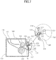
FIG 7 is a section view of the fixing unit according to a first modification example. -
FIG 8 is a perspective view of a fixing unit, a link mechanism, and a front opening/closing cover of a printer serving as an example of an image forming apparatus according to a second embodiment. -
FIG 9A is a section view of the fixing unit, the link mechanism, and the front opening/closing cover according to the second embodiment. -
FIG 9B is a section view of the fixing unit, the link mechanism, and the front opening/closing cover according to the second embodiment. -
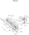
FIG 10 is a perspective view of a fixing unit, a link mechanism, and a rear opening/closing cover of a printer serving as an example of an image forming apparatus according to a third embodiment. -
FIG 11A is a section view of the fixing unit, the link mechanism, and the rear opening/closing cover according to the third embodiment. -
FIG 11B is a section view of the fixing unit, the link mechanism, and the rear opening/closing cover according to the third embodiment. -
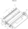
FIG 12 is a perspective view of a fixing unit, a link mechanism, and a process cartridge of a printer serving as an example of an image forming apparatus according to a fourth embodiment. -
FIG 13A is a perspective view of the fixing unit, the link mechanism, and the process cartridge according to the fourth embodiment. -
FIG 13B is a perspective view of the fixing unit, the link mechanism, and the process cartridge according to the fourth embodiment. - Embodiments of the present invention will be described in detail below with reference to drawings.
-
FIG 1 is a schematic longitudinal section view of aprinter 100 serving as an example of an image forming apparatus according to a first embodiment. Theprinter 100 is a laser beam printer of an electrophotographic system that forms a monochromatic toner image. - The
printer 100 includes anapparatus body 101, and an exterior 102 covering theapparatus body 101. Theapparatus body 101 includes abody frame 110, asheet feeding portion 120 that feeds a sheet S, and aconveyance roller pair 130 that conveys the sheet S fed by thesheet feeding portion 120. In addition, theapparatus body 101 includes animage forming portion 140 that forms a toner image on the sheet S conveyed by theconveyance roller pair 130, and afixing unit 150 including afixing portion 300 that fixes the toner image formed on the sheet S. In addition, theapparatus body 101 includes adischarge roller pair 160 capable of discharging the sheet S onto adischarge tray 161. Examples of the sheet S include recording media such as paper sheets such as plain paper sheets and envelops, plastic films for overhead projectors (overhead transparencies: OHTs), and cloths. - At least part of the
exterior 102, which is part of an upper portion of theexterior 102 in the first embodiment, is an opening/closing cover 103 serving as an example of an opening/closing member. The opening/closing cover 103 is supported to be openable and closable in an up-down direction with respect to thebody frame 110. - The
body frame 110 is a frame body formed from a metal plate and includes a pair of unillustrated side plates. Thebody frame 110 supports thesheet feeding portion 120, theconveyance roller pair 130, theimage forming portion 140, thefixing unit 150, and the discharge roller pair 160 directly, or indirectly via unillustrated members. - When an image formation job is input to the
printer 100, an image formation process by theimage forming portion 140 is started on the basis of image information input from an external computer or the like connected to theprinter 100. Theimage forming portion 140 includes aprocess cartridge 200 serving as an example of a cartridge, alaser scanner 250 serving as an example of an exposing portion, and atransfer roller 202 serving as an example of a transfer portion. - The
process cartridge 200 is inserted in thebody frame 110 along an unillustrated guide so as to be able to be pulled out. Theprocess cartridge 200 is urged by an unillustrated pressing member when being inserted into thebody frame 110, thus abuts an unillustrated abutment portion, and is thus positioned with respect to thebody frame 110. - In the present embodiment, the
process cartridge 200 can be exposed to the outside by opening the opening/closing cover 103, and thus a user can perform an insertion/removal operation of theprocess cartridge 200. Theprocess cartridge 200 includes aphotosensitive drum 201 serving as an image bearing member, and an unillustrated charging unit and an unillustrated developing unit that are disposed around thephotosensitive drum 201. - A pair of end portions of the
photosensitive drum 201 in the longitudinal direction are rotatably supported by a casing of theprocess cartridge 200. The driving force of an unillustrated driving motor is transmitted to one end portion of thephotosensitive drum 201 via an unillustrated drive transmission mechanism, and thus thephotosensitive drum 201 is rotationally driven in an arrow A direction inFIG 1 . - The surface of the
photosensitive drum 201 is an organic photoconductor layer, and is uniformly charged by being subjected to a charging bias from an unillustrated charging roller of the charging unit. Thelaser scanner 250 radiates laser light toward thephotosensitive drum 201 on the basis of input image information. The laser light emitted from thelaser scanner 250 exposes the surface of thephotosensitive drum 201, and thus an electrostatic latent image is formed on the surface of thephotosensitive drum 201. An unillustrated developing unit causes toner to attach to the surface of thephotosensitive drum 201 on which the electrostatic latent image has been formed, and thus the electrostatic latent image is developed. As a result of this, a monochromatic toner image is formed on the surface of thephotosensitive drum 201. - The sheet S is fed from the
sheet feeding portion 120 in parallel with the image formation process described above. Thesheet feeding portion 120 includes an unillustrated feeding tray, aninner plate 121, apickup roller 122, afeeding roller 123, and aseparation roller 124. Theinner plate 121 is supported by the unillustrated feeding tray so as to be able to ascend and descend, and is pushed upward by an unillustrated inner plate lifting/lowering mechanism. Theinner plate 121 is pushed up by the unillustrated inner plate lifting/lowering mechanism, and thus the downstream end of the sheet S supported on theinner plate 121 is pushed against thepickup roller 122. In this state, thepickup roller 122 feeds the uppermost sheet S among sheets S supported on theinner plate 121 to thefeeding roller 123. Thefeeding roller 123 is driven at a predetermined timing by an unillustrated driving motor and an unillustrated drive transmission mechanism, and conveys the sheet S fed by thepickup roller 122 to theconveyance roller pair 130. In the case where a plurality of sheets S are fed by thepickup roller 122, the plurality of sheets S are separated by theseparation roller 124, and only the uppermost one of the sheets S is conveyed to theconveyance roller pair 130. - The sheet S conveyed to the
conveyance roller pair 130 is conveyed by theconveyance roller pair 130 to a transfer nip where thephotosensitive drum 201 and thetransfer roller 202 abut each other. A predetermined bias voltage is applied by thetransfer roller 202 to the sheet S conveyed to the transfer nip, and thus the toner image on thephotosensitive drum 201 is transferred onto the sheet S. - The fixing
unit 150 includes a fixingframe 310 that supports the fixingportion 300. The fixingframe 310 is attached and fixed to thebody frame 110, and is thus supported by thebody frame 110. As a result of this, the fixingunit 150 is attachable to and detachable from thebody frame 110, and ease of assembly and maintenance of theprinter 100 is improved. - The fixing
frame 310 includes afront side portion 311 opposing thetransfer roller 202, and anupper portion 312 opposing thedischarge roller pair 160. An opening HI that the sheet S can pass through is provided in thefront side portion 311 of the fixingframe 310. Aconveyance guide 170 extending approximately horizontally is disposed between thetransfer roller 202 and the opening HI of the fixingframe 310. The sheet S onto which the toner image has been transferred is guided to the fixingunit 150 by theconveyance guide 170, leading to the fixingportion 300 through the opening HI. - The fixing
portion 300 includes aheating roller 301 and a pressurizingroller 302. Theheating roller 301 is heated by a heat source. Examples of the heat source include a heat generating member such as a halogen lamp or a ceramic heater, and a heat generating mechanism of an induction heating system. A fixing nip N is formed by theheating roller 301 and the pressurizingroller 302 abutting each other. The sheet S onto which the toner image has been transferred is nipped and conveyed to the fixing nip N of the fixingportion 300, and is thus subjected to a predetermined heat and a predetermined pressure. As a result of this, the toner image on the sheet S is melted to adhere, that is, fixed thereto, and thus an image is formed on the sheet S. - An opening H2 that the sheet S can pass through is provided in the
upper portion 312 of the fixingframe 310. Conveyance guides 181 and 182 extending approximately vertically are disposed between the opening H2 of the fixingframe 310 and thedischarge roller pair 160. The sheet S on which an image has been formed by the fixingportion 300 is conveyed to the outside of the fixingframe 310 through the opening H2, is guided by the conveyance guides 181 and 182 to thedischarge roller pair 160, and is discharged onto thedischarge tray 161 by thedischarge roller pair 160. - To be noted, although the
printer 100 of the first embodiment has a configuration capable of only simplex printing in which an image is formed on a first surface of the sheet S, a configuration capable of duplex printing in which images of both the first surface and a second surface of the sheet S may be employed. That is, a configuration in which a duplex conveyance path is provided downstream of the fixingportion 300 in the sheet conveyance direction and the sheet S on the first surface of which an image has been formed is guided to the transfer nip through the duplex conveyance path may be employed. - In addition, although a case where the fixing
portion 300 includes theheating roller 301 has been described, the configuration is not limited to this, and a fixing film constituted by a flexible sleeve including an unillustrated heater may be provided instead of theheating roller 301. - Here, when the opening/
closing cover 103 is opened and theprocess cartridge 200 is pulled out from thebody frame 110, thetransfer roller 202, theconveyance guide 170, and thefront side portion 311 of the fixingframe 310 are exposed. As a result of this, the user can easily remove a sheet jammed inside theprinter 100. -
FIG 2 is a perspective view of the fixingunit 150 according to the first embodiment.FIGS. 3A and 3B are section views of the fixingunit 150 according to the first embodiment. - The
heating roller 301 and the pressurizingroller 302, particularly theheating roller 301, are heated by a heat source such as an unillustrated heater, and therefore have a portion that is heated to a high temperature. The fixingframe 310 is disposed to surround the fixingportion 300. The fixingframe 310 is constituted to include, for example, a metal plate. - The longitudinal direction of the fixing
portion 300, that is, the longitudinal direction of theheating roller 301 and the pressurizingroller 302 will be referred to as an X direction. The X direction also serves as a width direction of the sheet S. The fixingportion 300 is disposed inside the fixingframe 310, and both end portions of the fixingportion 300 in the X direction are supported by the fixingframe 310. As described above, the fixingframe 310 has the two openings H1 and H2 that the sheet S can pass through. The opening HI is provided on the sheet inlet side of the fixingframe 310, and the opening H2 is provided on the sheet outlet side of the fixingframe 310. - The fixing
frame 310 surrounding the fixingportion 300 does not mean that the fixingframe 310 seals the fixingportion 300, and means that the fixingframe 310 partially covers the fixingportion 300. That is, the fixingframe 310 may have an opening in addition to the openings HI and H2, and does not have to cover some part of the fixingportion 300 as long as it is difficult for the user's hand to touch the high-temperature portion of the fixingportion 300. For example, as illustrated inFIG 2 , both end portions of the fixingframe 310 in the X direction may be open. In addition, an opening of a size that the user's finger does not pass through may be provided in the fixingframe 310. In addition, for example, an opening may be provided at a position that the user's hand is difficult to reach in the fixingframe 310. In addition, for example, a gap may be provided between the fixingframe 310 and thebody frame 110, and an end portion of the fixingportion 300 in the X direction may be exposed from the fixingframe 310 through the gap. - The openings H1 and H2 are each formed in such a size that both end portions in the X direction of the sheet S of the maximum size among sheets on which image formation can be performed by the
printer 100 can pass therethrough without touching the fixingframe 310, and are each an elongated hole having a rectangular shape extending in the X direction in the present embodiment. To be noted, the shapes of the openings H1 and H2 are not limited to this, and for example, end portions of the openings H1 and H2 in the X direction may extend to end portions of the fixingframe 310 in the X direction. - In a state in which the opening/
closing cover 103 is open and theprocess cartridge 200 is pulled out from thebody frame 110, the opening HI is at a position where the user's hand can reach, and the opening H2 is at a position difficult for the user's hand to reach. In the present embodiment, the fixingunit 150 includes ashutter 320 that opens and closes the opening HI. Theshutter 320 will be hereinafter referred to as a fixing shutter. To be noted,FIG 3A illustrates a state in which the fixingshutter 320 is open, andFIG 3B illustrates a state in which the fixingshutter 320 is closed. - The fixing
shutter 320 is provided to be movable to an open position P1 illustrated inFIG 3A where the fixingshutter 320 opens the opening HI and a closed position P2 illustrated inFIG 3B where the fixingshutter 320 closes the opening HI. Here, when the fixingshutter 320 moves to the closed position P2, the entirety of the opening HI may be covered by the fixingshutter 320, or part of the opening HI may be not covered by the fixingshutter 320 as long as the user's finger does not enter the opening HI. For example, an end portion of the opening HI in the X direction does not have to be covered by the fixingshutter 320, or an opening such as a hole or a slit of a size that the user's finger does not pass through may be provided in the fixingshutter 320. - The fixing
unit 150 includes aholder 330 that supports the fixingshutter 320 such that the fixingshutter 320 is movable between the open position P1 and the closed position P2. Theholder 330 is attached and fixed to the fixingframe 310. As a result of this, the fixingshutter 320 is supported by thebody frame 110 via theholder 330 and the fixingframe 310. In the present embodiment, the fixingshutter 320 is pivotably, that is, swingably supported by theholder 330. The fixingshutter 320 can move between the open position P1 and the closed position P2 by pivoting with respect to theholder 330, that is, the fixingframe 310. Specifically, the fixingshutter 320 includes ashutter body 321 extending in the X direction, and asupport shaft 322 provided in theshutter body 321. Thesupport shaft 322 is pivotably supported by theholder 330. As a result of this, the fixingshutter 320 is supported by theholder 330 so as to be pivotable about thesupport shaft 322. - In addition, the fixing
unit 150 includes a fixingshutter spring 340 serving as an example of an urging portion, and anabutment portion 335 that the fixingshutter 320 abuts to be positioned at the open position P1. The fixingshutter spring 340 is a spring that urges the fixingshutter 320 toward the open position P1 by an urging force F1, and is a torsion coil spring in the present embodiment. A coil portion of the fixingshutter spring 340 is provided on thesupport shaft 322, a first end of the fixingshutter spring 340 abuts theshutter body 321 of the fixingshutter 320, and a second end of the fixingshutter spring 340 abuts the fixingframe 310. As a result of this, the urging force F1 of the fixingshutter spring 340 acts on the fixingshutter 320. Further, as illustrated inFIG 3A , the fixingshutter 320 pivots in the counterclockwise direction by the urging force F1 of the fixingshutter spring 340, and abuts theabutment portion 335. - The
abutment portion 335 is fixed to theholder 330 fixed to the fixingframe 310. That is, theabutment portion 335 is indirectly fixed to the fixingframe 310 via theholder 330 by being fixed to theholder 330, and is thus indirectly fixed to thebody frame 110 via theholder 330 and the fixingframe 310. As described above, theabutment portion 335 is positioned and fixed by the fixingframe 310, that is, thebody frame 110, with high precision. Therefore, the fixingshutter 320 is positioned at the open position P1 with high precision by abutting theabutment portion 335 that is positioned with high precision. - As illustrated in
FIG 3A , by moving the fixingshutter 320 to the open position P1 by the urging force F1 of the fixingshutter spring 340, the fixing nip N of the fixingportion 300 can be exposed to the outside of the fixingframe 310 through the opening H1. Further, as a result of theshutter body 321 of the fixingshutter 320 abutting theabutment portion 335, the fixingshutter 320 is positioned at the open position P1 with high precision. Therefore, a sheet conveyance path wide enough for the sheet S to pass through can be secured in the opening HI without increasing the size of theprinter 100. As a result of this, contact of the sheet S guided to the fixing nip N through the opening HI with the fixingframe 310 or the fixingshutter 320 in image formation can be reduced. Therefore, jam of the sheet S in the opening HI and disturbance of the toner image formed on the sheet S can be reduced. - In addition, since the fixing
shutter 320 pivots about thesupport shaft 322 to move to the open position P1 and the closed position P2, the size of theprinter 100 can be reduced as compared with a case where the fixing shutter moves to the open position and the closed position by linear movement. - As illustrated in
FIG 3B , the fixingshutter 320 includes an abuttingportion 323 provided at an end portion of theshutter body 321 in the X direction. The abuttingportion 323 is disposed outside the sheet conveyance path. The fixingframe 310 includes anabutment portion 336 that the abuttingportion 323 of the fixingshutter 320 abuts when the fixingshutter 320 moves to the closed position P2. As a result of the abuttingportion 323 of the fixingshutter 320 abutting theabutment portion 336, the fixingshutter 320 is positioned at the closed position P2 with high precision. As a result of the fixingshutter 320 moving to the closed position P2, the fixing nip N of the fixingportion 300 is covered by the fixingshutter 320. - In the present embodiment, the
printer 100 includes alink mechanism 350 that opens and closes the fixingshutter 320 in an interlocked manner with an opening/closing operation of the opening/closing cover 103 as illustrated inFIG 1 . Thelink mechanism 350 moves the fixingshutter 320 to the closed position P2 against the urging force F1 of the fixingshutter spring 340 in accordance with the opening operation of the opening/closing cover 103. -
FIG 4 is a perspective view of thelink mechanism 350 and the fixingunit 150 according to the first embodiment.FIGS. 5A and 5B are section views of thelink mechanism 350 and the fixingunit 150 according to the first embodiment. To be noted,FIG 5A illustrates a state in which the fixingshutter 320 is open, andFIG 5B illustrates a state in which the fixingshutter 320 is closed. - The
link mechanism 350 is disposed at a position corresponding to the abuttingportion 323 of the fixingshutter 320. Thelink mechanism 350 includes aswitching link 351 serving as an example of a first link member, amovable link 352 serving as an example of a second link member, and aswitching link spring 353 serving as an example of a link urging portion. - The
switching link 351 is provided to be movable to a separation position P3 illustrated inFIG 5A where theswitching link 351 is separated from the abuttingportion 323 of the fixingshutter 320, and an abutting position P4 illustrated inFIG 5B where theswitching link 351 abuts the abuttingportion 323 of the fixingshutter 320. In the present embodiment, theswitching link 351 is pivotably (swingably) supported by an unillustrated holder. The unillustrated holder is fixed to thebody frame 110 ofFIG 1 . The switching link 351 can move between the separation position P3 of the abutting position P4 by pivoting with respect to the unillustrated holder. Specifically, theswitching link 351 includes alink body 3511 and asupport shaft 3512 provided in thelink body 3511. Thesupport shaft 3512 is pivotably supported by the unillustrated holder. As a result of this, theswitching link 351 is supported by the unillustrated holder so as to be pivotable about thesupport shaft 3512. - The
switching link spring 353 is a spring that urges theswitching link 351 toward the abutting position P4 by an urging force F2, and is a torsion coil spring in the present embodiment. The urging force F2 of theswitching link spring 353 is set to be larger than the urging force F1 of the fixingshutter spring 340. Theswitching link spring 353 is provided on thesupport shaft 3512 of theswitching link 351. - The
movable link 352 is a link member that moves theswitching link 351 to the separation position P3 against the urging force F2 of theswitching link spring 353 in accordance with a closing operation of the opening/closing cover 103 illustrated inFIG 1 . Themovable link 352 is linearly movably supported by an unillustrated holder. The unillustrated holder is fixed to thebody frame 110 ofFIG 1 . Themovable link 352 linearly moves with respect to the unillustrated holder, and thus can abut or be separated from theswitching link 351. - As illustrated in
FIG 5A , themovable link 352 abuts and presses theswitching link 351, and thus pivots theswitching link 351 in a counterclockwise direction serving as a first direction against the urging force F2 of theswitching link spring 353 to move theswitching link 351 to the separation position P3. As a result of this, the fixingshutter 320 is positioned at the open position P1 by being urged by the fixingshutter spring 340 when theswitching link 351 is positioned at the separation position P3. That is, the restriction by theswitching link 351 is cancelled, and the fixingshutter 320 pivots in the counterclockwise direction by the urging force F1 of the fixingshutter spring 340 to abut theabutment portion 335, and is thus positioned at the open position P1 with high precision. - In addition, as illustrated in
FIG 5B , when themovable link 352 is separated from theswitching link 351, theswitching link 351 pivots in a clockwise direction serving as a second direction opposite to the first direction by the urging force F2 of theswitching link spring 353 to come into contact with the abuttingportion 323. The urging force F2 of theswitching link spring 353 is larger than the urging force F1 of the fixingshutter spring 340. Therefore, theswitching link 351 presses the abuttingportion 323 of the fixingshutter 320 by the urging force F2 of theswitching link spring 353 against the urging force F1 of the fixingshutter spring 340, and moves to the abutting position P4 while pivoting the fixingshutter 320 in the clockwise direction. As a result of this, when theswitching link 351 is positioned at the abutting position P4, the fixingshutter 320 is pressed by theswitching link 351 against the urging force F1 of the fixingshutter spring 340, and is thus positioned at the closed position P2. That is, the fixingshutter 320 pivots about thesupport shaft 322 in the clockwise direction by the abuttingportion 323 being pressed by theswitching link 351 that is pivoting. Further, as a result of theswitching link 351 pivoting to the abutting position P4, the abuttingportion 323 abuts theabutment portion 336, and thus the fixingshutter 320 is positioned at the closed position P2 with high precision. -
FIGS. 6A and 6B are section views of the fixingunit 150, thelink mechanism 350, and the opening/closing cover 103 according to the first embodiment. To be noted,FIG 6A illustrates a state in which the fixingshutter 320 is open, andFIG 6B illustrates a state in which the fixingshutter 320 is closed. The opening/closing cover 103 is supported by thebody frame 110 so as to be pivotable about asupport shaft 1031. The opening/closing cover 103 has arecess portion 1032 that one end portion of themovable link 352 can fit in and be separated from. - As illustrated in
FIG 6A , when the opening/closing cover 103 switches from the open state to the closed state, the one end portion of themovable link 352 fits in therecess portion 1032 of the opening/closing cover 103, and thus themovable link 352 moves in an arrow A1 direction. As a result of themovable link 352 moving in the arrow A1 direction in accordance with the closing operation of the opening/closing cover 103, themovable link 352 abuts theswitching link 351, and pivots theswitching link 351 in the counterclockwise direction against the urging force F2 of theswitching link spring 353. As a result of this, theswitching link 351 moves to the separation position P3 where theswitching link 351 is separated from the abuttingportion 323 of the fixingshutter 320. As a result of theswitching link 351 being separated from the fixingshutter 320, the fixingshutter 320 is caused to abut theabutment portion 335 by the urging force F1 of the fixingshutter spring 340, and is thus positioned at the open position P1. As a result of this, the fixing nip N is exposed through the opening HI. - In addition, as illustrated in
FIG 6B , when the opening/closing cover 103 switches from the closed state to the open state, the one end portion of themovable link 352 is separated from therecess portion 1032 of the opening/closing cover 103, and is thus pressed by the opening/closing cover 103 in an arrow A2 direction opposite to the arrow A1 direction. As a result of this, themovable link 352 moves in the arrow A2 direction in accordance with the opening operation of the opening/closing cover 103. As a result of themovable link 352 moving in the arrow A2 direction, themovable link 352 is separated from theswitching link 351, and thus theswitching link 351 pivots in the clockwise direction by the urging force F2 of theswitching link spring 353. As a result of theswitching link 351 moving to the abutting position P4 against the urging force F1 of the fixingshutter spring 340, the abuttingportion 323 of the fixingshutter 320 abuts theabutment portion 336, and thus the fixingshutter 320 is positioned at the closed position P2. As a result of this, the fixing nip N is covered by the fixingshutter 320. - As described above, according to the first embodiment, the
switching link 351 of thelink mechanism 350 is separated from the fixingshutter 320 by closing the opening/closing cover 103. Since the fixingshutter 320 is urged toward the open position P1 by the urging force F1 of the fixingshutter spring 340, the fixingshutter 320 pivots to abut theabutment portion 335, and is thus positioned at the open position P1 with high precision. - In addition, the fixing
shutter spring 340 provided on thesupport shaft 322 of the fixingshutter 320 is a member that moves the fixingshutter 320 to the open position P1. Therefore, as compared with a configuration in which the fixing shutter is retracted from the sheet conveyance path by an interlocking member that operates in an interlocked manner with the closing operation of the opening/closing cover, the configuration for retracting the fixingshutter 320 from the sheet conveyance path can be simplified, and the size of theprinter 100 can be reduced. In this manner, the fixingshutter 320 can be reliably retracted from the sheet conveyance path even in the case where the size of theprinter 100 is reduced. - In addition, in the first embodiment, the urging force F2 of the
switching link spring 353 is set to be larger than the urging force F1 of the fixingshutter spring 340. When the user opens the opening/closing cover 103 to remove a jammed sheet or replace theprocess cartridge 200, the inside of theapparatus body 101 is exposed. In this state, the fixingshutter 320 is positioned at the closed position P2 by the urging force F2 of theswitching link spring 353 against the urging force F1 of the fixingshutter spring 340. Therefore, the user's finger touching a high-temperature portion of the fixingportion 300 through the opening HI can be suppressed. - In addition, in the case where a jam of the sheet has occurred on the upstream side of the fixing
portion 300 in a state in which the sheet is nipped in the fixingportion 300, the user performs a jam removing operation of pulling the sheet out through the opening HI. The urging force F1 of the fixingshutter spring 340 assists the pulling force of the user pulling out the jammed sheet, and the urging force F2 of theswitching link 351 is relieved by the urging force F1, which facilitates pulling out the jammed sheet. As a result of this, the usability for removing the jam on the upstream side of the fixingportion 300 is improved. - To be noted, although a case where the
holder 330 is attached and fixed to the fixingframe 310 has been described in the first embodiment, the configuration is not limited to this.FIG 7 is a section view of the fixingunit 150 of the first modification example. For example, as illustrated inFIG 7 , theholder 330 to which theabutment portion 335 is fixed may be fixed to thebody frame 110. In addition, although illustration thereof is omitted, theabutment portion 335 may be directly attached and fixed to the fixingframe 310 not via theholder 330. - A printer serving as an example of an image forming apparatus according to a second embodiment will be described.
FIG 8 is a perspective view of the fixingunit 150, alink mechanism 350A, and a front opening/closing cover 103A of the printer serving as an example of the image forming apparatus according to the second embodiment.FIGS. 9A and 9B are section views of the fixingunit 150, thelink mechanism 350A, and the front opening/closing cover 103A according to the second embodiment. - In the first embodiment, a configuration in which the fixing
shutter 320 of the fixingunit 150 opens and closes the opening HI in accordance with the opening/closing operation of the opening/closing cover 103 has been described. In the second embodiment, a configuration in which the fixingshutter 320 of the fixingunit 150 opens and closes the opening HI in accordance with the opening/closing operation of the front opening/closing cover 103A will be described. To be noted, elements other than the front opening/closing cover 103A and thelink mechanism 350A in the printer of the second embodiment are substantially the same as the elements other than the opening/closing cover 103 and thelink mechanism 350 of theprinter 100 of the first embodiment, and therefore the description thereof will be omitted. - The printer of the second embodiment includes the fixing
unit 150, thelink mechanism 350A, and the front opening/closing cover 103A. The front opening/closing cover 103A serves as an example of an opening/closing member. The front opening/closing cover 103A is a part of the exterior of the printer, and is a front portion of the exterior. The front opening/closing cover 103A is supported so as to be openable and closable with respect to thebody frame 110 ofFIG 1 . - The fixing
unit 150 includes the fixingportion 300, the fixingframe 310, the fixingshutter 320, the fixingshutter spring 340, theholder 330, theabutment portion 335, and theabutment portion 336 as described in the first embodiment. The opening/closing operation of the fixingshutter 320 is the same as that described in the first embodiment. To be noted,FIG 9A illustrates a state in which the fixingshutter 320 is open, andFIG 9B illustrates a state in which the fixingshutter 320 is closed. - The front opening/
closing cover 103A is supported by thebody frame 110 to be pivotable about asupport shaft 1031A. Thelink mechanism 350A includes theswitching link 351 and theswitching link spring 353 configured as described in the first embodiment. Theswitching link 351 serves as an example of a first link member, and theswitching link spring 353 serves as an example of a link urging portion. In addition, thelink mechanism 350A includes amovable link 352A serving as an example of a second link member, and a holdinglink 354A. - The
movable link 352A is a link member that linearly moves in the horizontal direction in an interlocked manner with the opening/closing operation of the front opening/closing cover 103A, and is linearly movably supported by an unillustrated holder. The unillustrated holder is fixed to thebody frame 110 ofFIG 1 . Themovable link 352A linearly moves with respect to the unillustrated holder, and thus can abut or be separated from theswitching link 351. - In the second embodiment, a configuration in which the front opening/
closing cover 103A being opened or closed linearly moves themovable link 352A via the holdinglink 354A. The holdinglink 354A is supported by thesupport shaft 1032A of the front opening/closing cover 103A to be pivotable about thesupport shaft 1032A. The holdinglink 354A has an elongatedhole 3541A. Apin 3521A provided at one end portion of themovable link 352A is inserted in theelongated hole 3541A of the holdinglink 354A so as to be slidable along theelongated hole 3541A of the holdinglink 354A. As a result of this, themovable link 352A is linearly moved in the horizontal direction in accordance with the opening/closing operation of the front opening/closing cover 103A. - As illustrated in
FIG 9A , themovable link 352A moves in the arrow A1 direction in accordance with the closing operation of the front opening/closing cover 103A. Themovable link 352A moving in the arrow A1 direction abuts theswitching link 351 to move theswitching link 351 to the separation position P3 against the urging force F2 of theswitching link spring 353. As a result of this, the fixingshutter 320 is positioned at the open position P1 by being urged by the fixingshutter spring 340 and abutting theabutment portion 335 when theswitching link 351 is positioned at the separation position P3. That is, the restriction by theswitching link 351 is cancelled, and the fixingshutter 320 pivots by the urging force F1 of the fixingshutter spring 340 to abut theabutment portion 335, and is thus positioned at the open position P1 with high precision. Therefore, a sheet conveyance path wide enough for the sheet to pass through can be secured in the opening HI without increasing the size of the printer. As a result of this, contact of the sheet guided to the fixing nip N through the opening HI with the fixingframe 310 or the fixingshutter 320 in image formation can be reduced. Therefore, jam of the sheet in the opening HI and disturbance of the toner image formed on the sheet can be reduced. - In addition as illustrated in
FIG 9B , themovable link 352A moves in the arrow A2 direction opposite to the arrow A1 direction in accordance with the opening operation of the front opening/closing cover 103A. As a result of themovable link 352A moving in the arrow A2 direction being separated from theswitching link 351, theswitching link 351 pivots by the urging force F2 of theswitching link spring 353. The urging force F2 of theswitching link spring 353 is larger than the urging force F1 of the fixingshutter spring 340. Therefore, theswitching link 351 presses the abuttingportion 323 of the fixingshutter 320 by the urging force F2 of theswitching link spring 353 against the urging force F1 of the fixingshutter spring 340, and thus moves to the abutting position P4 while pivoting the fixingshutter 320. As a result of this, when theswitching link 351 is positioned at the abutting position P4, the fixingshutter 320 is pressed by theswitching link 351 against the urging force F1 of the fixingshutter spring 340, and thus the fixingshutter 320 is positioned at the closed position P2. That is, the fixingshutter 320 is pressed by theswitching link 351 to pivot about thesupport shaft 322 and abuts theabutment portion 336, and is thus positioned at the closed position P2 with high precision. Therefore, the user's finger touching the high-temperature portion of the fixingportion 300 through the opening HI can be suppressed. - A printer serving as an example of an image forming apparatus according to a third embodiment will be described.
FIG 10 is a perspective view of a fixingunit 150B, alink mechanism 350B, and a rear opening/closing cover 103B of the printer serving as an example of the image forming apparatus according to the third embodiment.FIGS. 11A and 11B are section views of the fixingunit 150B, thelink mechanism 350B, and the rear opening/closing cover 103B according to the third embodiment. - A configuration in which an opening of the fixing frame on the sheet inlet side is opened and closed has been described in the first and second embodiments. In the third embodiment, a configuration in which an opening of the fixing frame on the sheet outlet side is opened and closed will be described. To be noted, elements other than the fixing
unit 150B, the rear opening/closing cover 103B, and thelink mechanism 350B in the printer of the third embodiment are substantially the same as the elements other than the fixingunit 150, the opening/closing cover 103, and thelink mechanism 350 of theprinter 100 of the first embodiment, and therefore the description thereof will be omitted. - The printer of the third embodiment includes the fixing
unit 150B, thelink mechanism 350B, and the rear opening/closing cover 103B. The rear opening/closing cover 103B serves as an example of an opening/closing member. The fixingunit 150B includes the fixingportion 300 configured as described in the first embodiment. In addition, the fixingunit 150B includes a fixingframe 310B surrounding the fixingportion 300. The fixingframe 310B has an opening H11 on the sheet inlet side and an opening H12 on the sheet outlet side. The rear opening/closing cover 103B is a part of the exterior of the printer, and is a rear portion of the exterior. The rear opening/closing cover 103B is supported by thebody frame 110 ofFIG 1 so as to be pivotable about asupport shaft 1031B. As a result of this, the rear opening/closing cover 103B pivots about thesupport shaft 1031B, and is thus openable and closable with respect to thebody frame 110 ofFIG 1 . In addition, the rear opening/closing cover 103B and theconveyance guide 181 are integrally formed, and theconveyance guide 181 is openable and closable together with the rear opening/closing cover 103B. - When the
conveyance guide 181 is opened together with the rear opening/closing cover 103B, the sheet conveyance path defined by theconveyance guide 181 and theconveyance guide 182 ofFIG 1 can be opened. As a result of this, it becomes easier to remove the sheet jammed at the conveyance guides 181 and 182. To suppress the user's finger touching the high-temperature portion of the fixingportion 300 through the opening H12 in the jam removing operation, the fixingunit 150B of the third embodiment includes a fixingshutter 320B that opens and closes the opening H12. To be noted,FIG 11A illustrates a state in which the fixingshutter 320B is open, andFIG 11B illustrates a state in which the fixingshutter 320B is closed. - The fixing
shutter 320B is provided to be movable to an open position P11 illustrated inFIG 11A where the fixingshutter 320B opens the opening H12 and a closed position P12 illustrated inFIG 11B where the fixingshutter 320B closes the opening H12. Here, when the fixingshutter 320B moves to the closed position P12, the entirety of the opening H12 may be covered by the fixingshutter 320B, or part of the opening H12 may be not covered by the fixingshutter 320B as long as the user's finger does not enter the opening H12. - The fixing
unit 150B includes aholder 330B that supports the fixingshutter 320B such that the fixingshutter 320B is movable between the open position P11 and the closed position P12. Theholder 330B is attached and fixed to the fixingframe 310B. As a result of this, the fixingshutter 320B is supported by thebody frame 110 ofFIG 1 via theholder 330B and the fixingframe 310B. In the present embodiment, the fixingshutter 320B is pivotably, that is, swingably supported by theholder 330B. The fixingshutter 320B can move between the open position P11 and the closed position P12 by pivoting with respect to theholder 330B, that is, the fixingframe 310B. Specifically, the fixingshutter 320B includes ashutter body 321B extending in the X direction, and asupport shaft 322B provided in theshutter body 321B. Thesupport shaft 322B is pivotably supported by theholder 330B. As a result of this, the fixingshutter 320B is supported by theholder 330B so as to be pivotable about thesupport shaft 322B. - In addition, the fixing
unit 150B includes a fixingshutter spring 340B serving as an example of an urging portion, and anabutment portion 335B that the fixingshutter 320B abuts to be positioned at an open position P11. The fixingshutter spring 340B is a spring that urges the fixingshutter 320B toward the open position P11 by an urging force F3, and is a torsion coil spring in the present embodiment. The fixingshutter spring 340B is provided on thesupport shaft 322B so as to apply the urging force F3 to the fixingshutter 320B. - The
abutment portion 335B is fixed to theholder 330B fixed to the fixingframe 310B. That is, theabutment portion 335B is indirectly fixed to the fixingframe 310B via theholder 330B by being fixed to theholder 330B, and is thus indirectly fixed to thebody frame 110 via theholder 330B and the fixingframe 310B. As described above, theabutment portion 335B is positioned and fixed by the fixingframe 310B, that is, thebody frame 110, with high precision. Therefore, the fixingshutter 320B is positioned at the open position P11 with high precision by abutting theabutment portion 335B that is positioned with high precision. To be noted, theabutment portion 335B may be directly provided on the fixingframe 310B. - In addition, the fixing
shutter 320B includes an abuttingportion 323B provided at an end portion of theshutter body 321B in the X direction. Thelink mechanism 350B is disposed at a position corresponding to the abuttingportion 323B. Thelink mechanism 350B includes aswitching link 351B serving as an example of a first link member, apressing portion 352B serving as an example of a second link member, and aswitching link spring 353B serving as an example of a link urging portion. - The
switching link 351B is provided to be movable to a separation position P13 illustrated inFIG 11A where theswitching link 351B is separated from the abuttingportion 323B of the fixingshutter 320B, and an abutting position P14 illustrated inFIG. 11B where theswitching link 351B abuts the abuttingportion 323B of the fixingshutter 320B. In the present embodiment, theswitching link 351B is pivotably (swingably) supported by an unillustrated holder. The unillustrated holder is fixed to thebody frame 110 ofFIG 1 . Theswitching link 351B can move between the separation position P13 of the abutting position P14 by pivoting with respect to the unillustrated holder. Specifically, theswitching link 351B includes asupport shaft 3512B pivotably supported by the unillustrated holder. - The
switching link spring 353B is a spring that urges theswitching link 351B toward the abutting position P14 by an urging force F4, and is a torsion coil spring in the present embodiment. The urging force F4 of theswitching link spring 353B is set to be larger than the urging force F3 of the fixingshutter spring 340B. Theswitching link spring 353B is provided on thesupport shaft 3512B of theswitching link 351B. - The
pressing portion 352B is a link member that moves theswitching link 351B to the separation position P13 against the urging force F4 of theswitching link spring 353B in accordance with a closing operation of the rear opening/closing cover 103B. Thepressing portion 352B is fixed to the rear opening/closing cover 103B. Thepressing portion 352B abuts or is separated from theswitching link 351B when the rear opening/closing cover 103B is opened or closed. - As illustrated in
FIG 11A , when the rear opening/closing cover 103B is closed, thepressing portion 352B abuts theswitching link 351B, and thus moves theswitching link 351B to the separation position P13 against the urging force F4 of theswitching link spring 353B. As a result of this, the fixingshutter 320B abuts theabutment portion 335B and positioned at the open position P11 by being urged by the fixingshutter spring 340B when theswitching link 351B is positioned at the separation position P13. That is, the restriction by theswitching link 351B is cancelled, and the fixingshutter 320B pivots by the urging force F3 of the fixingshutter spring 340B to abut theabutment portion 335B, and is thus positioned at the open position P11 with high precision. As a result of this, the sheet guided out of the fixing nip N through the opening H12 touching the fixingframe 310B or the fixingshutter 320B can be suppressed. Therefore, occurrence of a jam of the sheet in the opening H12 can be suppressed. - In addition, as illustrated in
FIG 11B , when the rear opening/closing cover 103B is opened, thepressing portion 352B is separated from theswitching link 351B. As a result of this, theswitching link 351B pivots by the urging force F4 of theswitching link spring 353B to abut the abuttingportion 323B of the fixingshutter 320B. The urging force F4 of theswitching link spring 353B is larger than the urging force F3 of the fixingshutter spring 340B. Therefore, theswitching link 351B presses the abuttingportion 323B of the fixingshutter 320B by the urging force F4 of theswitching link spring 353B against the urging force F3 of the fixingshutter spring 340B, and moves to the abutting position P14 while pivoting the fixingshutter 320B. As a result of this, when theswitching link 351B is positioned at the abutting position P14, the fixingshutter 320B is pressed by theswitching link 351B against the urging force F3 of the fixingshutter spring 340B, and is thus positioned at the closed position P12. That is, the fixingshutter 320B pivots about thesupport shaft 322B in the clockwise direction to abut the abutment portion 336B by being pressed by theswitching link 351B, and is thus positioned at the closed position P12 with high precision. - In this manner, the fixing
shutter 320B pivots about thesupport shaft 322B to move to the open position P11 and the closed position P12, and therefore the size of the printer can be reduced as compared with the case where the fixing shutter moves to the open position and the closed position by linear movement. - As described above, according to the third embodiment, the
switching link 351B of thelink mechanism 350B is separated from the fixingshutter 320B by closing the rear opening/closing cover 103B. Since the fixingshutter 320B is urged toward the open position P11 by the urging force F3 of the fixingshutter spring 340B, the fixingshutter 320B pivots to abut theabutment portion 335B, and is thus positioned at the open position P11 with high precision. - In addition, the fixing
shutter spring 340B provided on thesupport shaft 322B of the fixingshutter 320B is a member that moves the fixingshutter 320B to the open position P11. Therefore, as compared with a configuration in which the fixing shutter is retracted from the sheet conveyance path by an interlocking member that operates in an interlocked manner with the closing operation of the opening/closing cover, the configuration for retracting the fixingshutter 320B from the sheet conveyance path can be simplified, and the size of the printer can be reduced. In this manner, the fixingshutter 320B can be reliably retracted from the sheet conveyance path even in the case where the size of the printer is reduced. - In addition, in the third embodiment, the urging force F4 of the
switching link spring 353B is set to be larger than the urging force F3 of the fixingshutter spring 340B. When the user opens the rear opening/closing cover 103B to remove a jammed sheet, the sheet conveyance path constituted by the conveyance guide 108 is exposed. In this state, the fixingshutter 320B is positioned at the closed position P12 by the urging force F4 of theswitching link spring 353B against the urging force F3 of the fixingshutter spring 340B. Therefore, the user's finger touching a high-temperature portion of the fixingportion 300 through the opening H12 can be suppressed. - In addition, in the case where a jam of the sheet has occurred on the downstream side of the fixing
portion 300 in a state in which the sheet is nipped in the fixingportion 300, the user performs a jam removing operation of pulling the sheet out through the opening H12. The urging force F3 of the fixingshutter spring 340B assists the pulling force of the user pulling out the jammed sheet, and the urging force F4 of theswitching link 351B is relieved by the urging force F3, which facilitates pulling out the jammed sheet. As a result of this, the usability for removing the jam on the downstream side of the fixingportion 300 is improved. - A printer serving as an example of an image forming apparatus according to a fourth embodiment will be described.
FIG 12 is a perspective view of the fixingunit 150, alink mechanism 350C, and aprocess cartridge 200 of the printer serving as an example of the image forming apparatus according to the fourth embodiment.FIGS. 13A and 13B are section views of the fixingunit 150, thelink mechanism 350C, and theprocess cartridge 200 according to the fourth embodiment. - In the first to third embodiments, a configuration in which the fixing shutter is moved in an interlocked manner with the opening/closing operation of the opening/closing member has been described. In the fourth embodiment, a configuration in which the fixing
shutter 320 is moved in an interlocked manner with the insertion/removal operation of theprocess cartridge 200 will be described. To be noted, elements other than thelink mechanism 350C in the printer of the fourth embodiment are substantially the same as the elements other than thelink mechanism 350 of theprinter 100 of the first embodiment, and therefore the description thereof will be omitted. - The printer of the fourth embodiment includes the fixing
unit 150, theprocess cartridge 200, and thelink mechanism 350C. The configuration of the fixingunit 150 and theprocess cartridge 200 is the same as that described in the first embodiment. - The
link mechanism 350C includes theswitching link 351 and theswitching link spring 353. Theswitching link 351 serves as an example of a first link member. Theswitching link spring 353 serves as an example of a link urging portion. The configuration of theswitching link 351 and theswitching link spring 353 is as described in the first embodiment. That is, theswitching link 351 is supported by an unillustrated holder so as to be movable to the separation position P3 where theswitching link 351 is separated from the fixingshutter 320 and the abutting position P4 where theswitching link 351 abuts the fixingshutter 320. Theswitching link spring 353 is a spring that urges theswitching link 351 toward the abutting position P4. The urging force F2 of theswitching link spring 353 is larger than the urging force F1 of the fixingshutter spring 340. Further, the fixingshutter 320 is positioned at the open position P1 by being urged by the fixingshutter spring 340 when theswitching link 351 is positioned at the separation position P3. In addition, when theswitching link 351 is positioned at the abutting position P4, the fixingshutter 320 is pressed by theswitching link 351 against the urging force F1 of the fixingshutter spring 340, and is thus positioned at the closed position P2. - In addition, the
link mechanism 350C includes amovable link 352C serving as an example of a second link member. Themovable link 352C is a link member that moves theswitching link 351 to the separation position P3 against the urging force F2 of theswitching link spring 353 in accordance with an operation of inserting theprocess cartridge 200 into thebody frame 110. Theprocess cartridge 200 includes apressing portion 210 disposed at a position corresponding to thelink mechanism 350C. Thepressing portion 210 is part of a side plate included in a casing of theprocess cartridge 200. - When the
process cartridge 200 is inserted into thebody frame 110, thepressing portion 210 of theprocess cartridge 200 abuts themovable link 352C and presses themovable link 352C in an arrow A1 direction as illustrated inFIG 13A . Then, themovable link 352C moves in the arrow A1 direction to abut theswitching link 351, and presses theswitching link 351. The switching link 351 pivots in a counterclockwise direction inFIG 13A against the urging force F2 of theswitching link spring 353. As a result of this, theswitching link 351 is separated from the abuttingportion 323 of the fixingshutter 320, and thus the fixingshutter 320 pivots in the counterclockwise direction inFIG 13A by the urging force F1 of the fixingshutter spring 340. Then, the fixingshutter 320 abuts theabutment portion 335, and is thus positioned at the open position P1. As a result of the fixingshutter 320 being positioned at the open position P1, the fixing nip N of the fixingportion 300 is exposed through the opening H1. - In addition, when the
process cartridge 200 is pulled out from thebody frame 110, thepressing portion 210 of theprocess cartridge 200 is separated from themovable link 352C as illustrated inFIG 13B . As a result of this, theswitching link 351 pivots in a clockwise direction inFIG 13B by the urging force F2 of theswitching link spring 353, and themovable link 352C is pressed by theswitching link 351 to move in an arrow A2 direction. Then, theswitching link 351 abuts the abuttingportion 323 of the fixingshutter 320 to press the fixingshutter 320, and pivots in the clockwise direction until the abuttingportion 323 of the fixingshutter 320 abuts theabutment portion 336. Then, as a result of the abuttingportion 323 abutting theabutment portion 336, the fixingshutter 320 is positioned at the closed position P2. As a result of the fixingshutter 320 being positioned at the closed position P2, the fixing nip N of the fixingportion 300 is covered by the fixingshutter 320. - As described above, according to the fourth embodiment, the
switching link 351 of thelink mechanism 350C is separated from the fixingshutter 320 by inserting theprocess cartridge 200 into thebody frame 110. Since the fixingshutter 320 is urged toward the open position P1 by the urging force F1 of the fixingshutter spring 340, the fixingshutter 320 pivots to abut theabutment portion 335, and is thus positioned at the open position P1 with high precision. - In addition, the fixing
shutter spring 340 provided on thesupport shaft 322 of the fixingshutter 320 is a member that moves the fixingshutter 320 to the open position P1. Therefore, as compared with a configuration in which the fixing shutter is retracted from the sheet conveyance path by an interlocking member that operates in an interlocked manner with the insertion/removal operation of the process cartridge, the configuration for retracting the fixingshutter 320 from the sheet conveyance path can be simplified, and the size of the printer can be reduced. In this manner, the fixingshutter 320 can be reliably retracted from the sheet conveyance path even in the case where the size of the printer is reduced. - In addition, in the fourth embodiment, the urging force F2 of the
switching link spring 353 is set to be larger than the urging force F1 of the fixingshutter spring 340. When the user pulls out theprocess cartridge 200 from thebody frame 110, the fixingunit 150 is exposed. In this state, the fixingshutter 320 is positioned at the closed position P2 by the urging force F2 of theswitching link spring 353 against the urging force F1 of the fixingshutter spring 340. Therefore, the user's finger touching a high-temperature portion of the fixingportion 300 through the opening HI can be suppressed. - In addition, in the case where a jam of the sheet has occurred on the upstream side of the fixing
portion 300 in a state in which the sheet is nipped in the fixingportion 300, the user performs a jam removing operation of pulling the sheet out through the opening HI. The urging force F1 of the fixingshutter spring 340 assists the pulling force of the user pulling out the jammed sheet, and the urging force F2 of theswitching link 351 is relieved by the urging force F1, which facilitates pulling out the jammed sheet. As a result of this, the usability for removing the jam on the upstream side of the fixingportion 300 is improved. - According to the present disclosure, the shutter can be positioned with high precision when opening the shutter.
- The present invention is not limited to the embodiments described above, and can be modified in many ways within the technical concept of the present invention. In addition, the effects described in the embodiments are merely enumeration of the most preferable effects that can be obtained from the present invention, and the effects of the present invention are not limited to those described in the embodiments.
- Although a monochromatic printer of an electrophotographic system has been described as an example of the image forming apparatus in the embodiments described above, the present invention is not limited to this. For example, the present invention may be applied to a full-color printer of an electrophotographic system including a plurality of process cartridges. In addition, the present invention may be applied to copiers, facsimile apparatuses, multifunctional apparatuses having functions of these, and the like in addition to printers.
- In addition, although a case where the image forming apparatus is of an electrophotographic system has been described in the embodiments described above, the present invention is not limited to this. For example, the present invention may be applied to an image forming apparatus of an electrostatic recording system or a magnetic recording system.
- In addition, although a case where the cartridge that is insertable into and removable from the body frame has been described in the embodiments described above, the present invention is not limited to this. For example, the present invention can be also applied to a case where the cartridge is a toner cartridge that supplies toner to a developing unit.
- While the present invention has been described with reference to exemplary embodiments, it is to be understood that the invention is not limited to the disclosed exemplary embodiments. The scope of the following claims is to be accorded the broadest interpretation so as to encompass all such modifications and equivalent structures and functions.
- An image forming apparatus includes an image forming portion configured to form a toner image on a sheet, a fixing portion (300) configured to heat and pressurize the sheet bearing the toner image to fix the toner image to the sheet, a shutter (320) provided to be movable to an open position (P1) at which the shutter (320) opens an opening that the sheet being conveyed toward the fixing portion (300) is able to pass through, and a closed position (P2) at which the shutter (320) closes the opening, an urging portion (340) configured to urge the shutter (320) toward the open position (P1), and an abutment portion (335) that the shutter (320) urged toward the open position (P1) by the urging portion (340) abuts to be positioned at the open position (P1).
Claims (17)
- An image forming apparatus comprising:an image forming portion (140) configured to form a toner image on a sheet;a fixing portion (300) configured to heat and pressurize the sheet bearing the toner image to fix the toner image to the sheet;a shutter (320,320B) provided to be movable to an open position (P1,P11) at which the shutter (320,320B) opens an opening (H1,H12) that the sheet being conveyed toward the fixing portion (300) is able to pass through, and a closed position (P2,P12) at which the shutter (320,320B) closes the opening (H1,H12);an urging portion (340,340B) configured to urge the shutter (320,320B) toward the open position (P1,P11); andan abutment portion (335,335B) that the shutter (320,320B) urged toward the open position (P1,P11) by the urging portion (340,340B) abuts to be positioned at the open position (P1,P11).
- The image forming apparatus according to claim 1, wherein the shutter (320,320B) is provided to be pivotable between the open position (P1,P11) and the closed position (P2,P12).
- The image forming apparatus according to claim 1 or 2, further comprising:a fixing frame (310,310B) in which the opening (H1,H12) is provided; anda holder (330,330B) attached to the fixing frame (310,310B),wherein the abutment portion (335,335B) is fixed to the fixing frame (310,310B) via the holder (330,330B).
- The image forming apparatus according to claim 3, wherein the shutter (320,320B) is supported by the fixing frame (310,310B) via the holder (330,330B).
- The image forming apparatus according to any one of claims 1 to 4, further comprising:a body frame (110);an opening/closing member (103,103A,103B) openably and closably supported with respect to the body frame (110); anda link mechanism (350,350A,350B) configured to move the shutter (320,320B) to the closed position (P2,P12) against an urging force of the urging portion (340,340B) in accordance with an opening operation of the opening/closing member (103,103A,103B).
- The image forming apparatus according to claim 5,wherein the link mechanism (350,350A,350B) includes a first link member (351,351B) movable to a separation position (P3,P13) where the first link member (351,351B) is separated from the shutter (320,320B), and an abutting position (P4,P14) where the first link member (351,351B) abuts the shutter (320,320B), andwherein in a case where the first link member (351,351B) is positioned at the separation position (P3,P13), the shutter (320,320B) is positioned at the open position (P1,P11) by being urged by the urging portion (340,340B), and in a case where the first link member (351,351B) is positioned at the abutting position (P4,P14), the shutter (320,320B) is positioned at the closed position (P2,P12) by being pressed by the first link member (351,351B) against an urging force of the urging portion (340,340B).
- The image forming apparatus according to claim 6, wherein the link mechanism (350,350A,350B) includesa link urging portion (353,353B) configured to urge the first link member (351,351B) toward the abutting position (P4,P14), anda second link member (352,352A,352B) configured to move the first link member (351,351B) to the separation position (P3,P13) against an urging force of the link urging portion (353,353B) in accordance with a closing operation of the opening/closing member (103,103A,103B).
- The image forming apparatus according to claim 7, wherein the urging force of the link urging portion (353,353B) is larger than the urging force of the urging portion (340,340B).
- The image forming apparatus according to any one of claims 5 to 8, wherein the opening/closing member (103,103A,103B) constitutes at least part of an exterior of the image forming apparatus.
- The image forming apparatus according to any one of claims 1 to 4, further comprising:a body frame (110); anda link mechanism (350C),wherein the image forming portion (140) includes a cartridge (200) that is insertable into and removable from the body frame (110), andwherein the link mechanism (350C) is configured to move the shutter (320) to the closed position (P2) against an urging force of the urging portion (340) in accordance with an operation of pulling the cartridge (200) out from the body frame (110).
- The image forming apparatus according to claim 10,wherein the link mechanism (350C) includes a first link member (351) movable to a separation position (P3) where the first link member (351) is separated from the shutter (320), and an abutting position (P4) where the first link member (351) abuts the shutter (320), andwherein in a case where the first link member (351) is positioned at the separation position (P3), the shutter (320) is positioned at the open position (P1) by being urged by the urging portion (340), and in a case where the first link member (351) is positioned at the abutting position (P4), the shutter (320) is positioned at the closed position (P2) by being pushed by the first link member (351) against the urging force of the urging portion (340).
- The image forming apparatus according to claim 11, wherein the link mechanism (350C) includesa link urging portion (353) configured to urge the first link member (351) toward the abutting position (P4), anda second link member (352C) configured to move the first link member (351) to the separation position (P3) against an urging force of the link urging portion (353) in accordance with an operation of inserting the cartridge (200) into the body frame (110).
- The image forming apparatus according to claim 12, wherein the urging force of the link urging portion (353) is larger than the urging force of the urging portion (340).
- A fixing unit comprising:a fixing portion (300) configured to heat and pressurize a sheet bearing a toner image to fix the toner image to the sheet;a shutter (320,320B) provided to be movable to an open position (P1,P11) at which the shutter (320,320B) opens an opening that the sheet being conveyed toward the fixing portion (300) is able to pass through, and a closed position (P2,P12) at which the shutter (320,320B) closes the opening;an urging portion (340,340B) configured to urge the shutter (320,320B) toward the open position (P1,P11); andan abutment portion (335,335B) that the shutter (320,320B) urged toward the open position (P1,P11) by the urging portion (340,340B) abuts to be positioned at the open position (P1,P11).
- The fixing unit according to claim 14, wherein the shutter (320,320B) is provided to be pivotable between the open position (P1,P11) and the closed position (P2,P12).
- The fixing unit according to claim 14 or 15, further comprising:a fixing frame (310,310B) in which the opening (H1,H12) is provided; anda holder (330,330B) attached to the fixing frame (310,310B),wherein the abutment portion (335,335B) is fixed to the fixing frame (310,310B) via the holder (330,330B).
- The fixing unit according to claim 16, wherein the shutter (320,320B) is supported by the fixing frame (310,310B) via the holder (330,330B).
Applications Claiming Priority (1)
| Application Number | Priority Date | Filing Date | Title |
|---|---|---|---|
| JP2021150220A JP7735132B2 (en) | 2021-09-15 | 2021-09-15 | Image forming apparatus and fixing unit |
Publications (2)
| Publication Number | Publication Date |
|---|---|
| EP4152102A1 true EP4152102A1 (en) | 2023-03-22 |
| EP4152102B1 EP4152102B1 (en) | 2025-12-24 |
Family
ID=83192006
Family Applications (1)
| Application Number | Title | Priority Date | Filing Date |
|---|---|---|---|
| EP22193595.0A Active EP4152102B1 (en) | 2021-09-15 | 2022-09-02 | Image forming apparatus and fixing unit |
Country Status (3)
| Country | Link |
|---|---|
| US (3) | US11822282B2 (en) |
| EP (1) | EP4152102B1 (en) |
| JP (1) | JP7735132B2 (en) |
Families Citing this family (12)
| Publication number | Priority date | Publication date | Assignee | Title |
|---|---|---|---|---|
| JP7735132B2 (en) * | 2021-09-15 | 2025-09-08 | キヤノン株式会社 | Image forming apparatus and fixing unit |
| US12044992B2 (en) * | 2022-01-31 | 2024-07-23 | Brother Kogyo Kabushiki Kaisha | Image-forming apparatus provided with mechanism for opening and closing shutter of fixing device |
| JP7797939B2 (en) * | 2022-03-30 | 2026-01-14 | ブラザー工業株式会社 | Fixing device and image forming apparatus |
| JP2024003995A (en) * | 2022-06-28 | 2024-01-16 | 富士フイルムビジネスイノベーション株式会社 | Image forming device |
| US12085887B2 (en) * | 2022-06-29 | 2024-09-10 | Brother Kogyo Kabushiki Kaisha | Fixing device including shutter pivotable about axis positioned downstream of nipping region in sheet conveying direction |
| US12282286B2 (en) * | 2022-09-29 | 2025-04-22 | Kyocera Document Solutions Inc. | Image forming apparatus including fixing device having shutter and lock member for holding shutter position |
| JP2024137539A (en) * | 2023-03-24 | 2024-10-07 | ブラザー工業株式会社 | Image forming device |
| JP2024176367A (en) * | 2023-06-08 | 2024-12-19 | 京セラドキュメントソリューションズ株式会社 | Fixing device and image forming apparatus equipped with same |
| JP2025021861A (en) * | 2023-08-01 | 2025-02-14 | ブラザー工業株式会社 | Image forming device |
| JP2025085537A (en) * | 2023-11-24 | 2025-06-05 | ブラザー工業株式会社 | Image forming apparatus and cartridge |
| JP2025085453A (en) * | 2023-11-24 | 2025-06-05 | ブラザー工業株式会社 | Image forming device |
| JP2025088541A (en) * | 2023-11-30 | 2025-06-11 | ブラザー工業株式会社 | Image forming device |
Citations (2)
| Publication number | Priority date | Publication date | Assignee | Title |
|---|---|---|---|---|
| JP2003140480A (en) | 2001-11-01 | 2003-05-14 | Canon Inc | Image forming device |
| US20190286023A1 (en) * | 2018-03-15 | 2019-09-19 | Canon Kabushiki Kaisha | Image forming apparatus |
Family Cites Families (14)
| Publication number | Priority date | Publication date | Assignee | Title |
|---|---|---|---|---|
| JPH0980943A (en) | 1995-09-08 | 1997-03-28 | Ricoh Co Ltd | Fixing device |
| JP4759161B2 (en) * | 2001-04-25 | 2011-08-31 | キヤノン株式会社 | Image forming apparatus |
| JP3922220B2 (en) | 2002-09-12 | 2007-05-30 | 松下電器産業株式会社 | Fixing apparatus and image forming apparatus having the same |
| US7003246B2 (en) | 2004-03-25 | 2006-02-21 | Lexmark International, Inc. | Fuser nip release mechanism |
| JP5921310B2 (en) | 2012-04-19 | 2016-05-24 | キヤノン株式会社 | Image forming apparatus |
| JP6381204B2 (en) | 2013-12-02 | 2018-08-29 | キヤノン株式会社 | Image forming apparatus |
| JP6504801B2 (en) | 2014-11-28 | 2019-04-24 | キヤノン株式会社 | Image forming device |
| JP2019040012A (en) | 2017-08-24 | 2019-03-14 | 京セラドキュメントソリューションズ株式会社 | Image forming apparatus |
| US20190107806A1 (en) * | 2017-10-10 | 2019-04-11 | Lexmark International, Inc. | Fuser shutter mechanism for an imaging device |
| JP6961471B2 (en) | 2017-11-24 | 2021-11-05 | キヤノン株式会社 | Image forming device |
| JP7027138B2 (en) * | 2017-11-30 | 2022-03-01 | キヤノン株式会社 | Image forming device and cartridge that can be attached to the image forming device |
| CN209070309U (en) | 2017-12-06 | 2019-07-05 | 广州麦普数码科技有限公司 | A kind of handle box |
| US11281154B2 (en) * | 2020-04-13 | 2022-03-22 | Lexmark International, Inc. | Shutter for imaging device fuser assembly triggered by cartridge |
| JP7735132B2 (en) * | 2021-09-15 | 2025-09-08 | キヤノン株式会社 | Image forming apparatus and fixing unit |
-
2021
- 2021-09-15 JP JP2021150220A patent/JP7735132B2/en active Active
-
2022
- 2022-08-29 US US17/897,703 patent/US11822282B2/en active Active
- 2022-09-02 EP EP22193595.0A patent/EP4152102B1/en active Active
-
2023
- 2023-10-16 US US18/487,580 patent/US12078953B2/en active Active
-
2024
- 2024-07-26 US US18/785,778 patent/US12529992B2/en active Active
Patent Citations (2)
| Publication number | Priority date | Publication date | Assignee | Title |
|---|---|---|---|---|
| JP2003140480A (en) | 2001-11-01 | 2003-05-14 | Canon Inc | Image forming device |
| US20190286023A1 (en) * | 2018-03-15 | 2019-09-19 | Canon Kabushiki Kaisha | Image forming apparatus |
Also Published As
| Publication number | Publication date |
|---|---|
| JP2023042846A (en) | 2023-03-28 |
| US20230082752A1 (en) | 2023-03-16 |
| EP4152102B1 (en) | 2025-12-24 |
| CN115808863A (en) | 2023-03-17 |
| US20240045368A1 (en) | 2024-02-08 |
| US12529992B2 (en) | 2026-01-20 |
| US20240385568A1 (en) | 2024-11-21 |
| JP7735132B2 (en) | 2025-09-08 |
| US12078953B2 (en) | 2024-09-03 |
| US11822282B2 (en) | 2023-11-21 |
Similar Documents
| Publication | Publication Date | Title |
|---|---|---|
| EP4152102B1 (en) | Image forming apparatus and fixing unit | |
| US10509361B2 (en) | Image forming apparatus and cartridge mountable on the same | |
| CN109839810B (en) | Image forming apparatus | |
| US9310724B2 (en) | Image heating unit, recording medium conveying unit and image forming apparatus | |
| EP1800879B1 (en) | Image forming apparatus including shutter arm unit | |
| US20250341805A1 (en) | Pull-in apparatus, image forming apparatus, sheet accommodating apparatus, and draw-out unit | |
| US11254536B2 (en) | Image forming apparatus | |
| US20250291285A1 (en) | Image forming apparatus | |
| US20190302687A1 (en) | Image forming apparatus | |
| EP4617792A1 (en) | Image forming apparatus | |
| US8923738B2 (en) | Image heating apparatus, fixing apparatus and image forming apparatus | |
| US8737892B2 (en) | Image forming apparatus | |
| CN115808863B (en) | Imaging device and fixing unit | |
| US9274495B2 (en) | Image forming apparatus having fixing unit whose projected portion is prevented from coming out of main assembly opening after entering main assembly recessed portion | |
| JP7790156B2 (en) | Image forming device | |
| US20220397856A1 (en) | Apparatus | |
| JP6828373B2 (en) | Image forming device | |
| US12339611B2 (en) | Image forming apparatus | |
| US20260093204A1 (en) | Image forming apparatus | |
| US20240015254A1 (en) | Document reading apparatus and image forming apparatus | |
| US20230150783A9 (en) | Sheet feeding apparatus, image reading apparatus and image forming apparatus | |
| JP6280605B2 (en) | Paper feeding device and image forming apparatus | |
| CN120161694A (en) | Imaging equipment | |
| JP2006003714A (en) | Image forming apparatus |
Legal Events
| Date | Code | Title | Description |
|---|---|---|---|
| PUAI | Public reference made under article 153(3) epc to a published international application that has entered the european phase |
Free format text: ORIGINAL CODE: 0009012 |
|
| STAA | Information on the status of an ep patent application or granted ep patent |
Free format text: STATUS: THE APPLICATION HAS BEEN PUBLISHED |
|
| AK | Designated contracting states |
Kind code of ref document: A1 Designated state(s): AL AT BE BG CH CY CZ DE DK EE ES FI FR GB GR HR HU IE IS IT LI LT LU LV MC MK MT NL NO PL PT RO RS SE SI SK SM TR |
|
| STAA | Information on the status of an ep patent application or granted ep patent |
Free format text: STATUS: REQUEST FOR EXAMINATION WAS MADE |
|
| 17P | Request for examination filed |
Effective date: 20230922 |
|
| RBV | Designated contracting states (corrected) |
Designated state(s): AL AT BE BG CH CY CZ DE DK EE ES FI FR GB GR HR HU IE IS IT LI LT LU LV MC MK MT NL NO PL PT RO RS SE SI SK SM TR |
|
| GRAP | Despatch of communication of intention to grant a patent |
Free format text: ORIGINAL CODE: EPIDOSNIGR1 |
|
| STAA | Information on the status of an ep patent application or granted ep patent |
Free format text: STATUS: GRANT OF PATENT IS INTENDED |
|
| INTG | Intention to grant announced |
Effective date: 20250714 |
|
| GRAS | Grant fee paid |
Free format text: ORIGINAL CODE: EPIDOSNIGR3 |
|
| GRAA | (expected) grant |
Free format text: ORIGINAL CODE: 0009210 |
|
| STAA | Information on the status of an ep patent application or granted ep patent |
Free format text: STATUS: THE PATENT HAS BEEN GRANTED |
|
| AK | Designated contracting states |
Kind code of ref document: B1 Designated state(s): AL AT BE BG CH CY CZ DE DK EE ES FI FR GB GR HR HU IE IS IT LI LT LU LV MC MK MT NL NO PL PT RO RS SE SI SK SM TR |
|
| REG | Reference to a national code |
Ref country code: CH Ref legal event code: F10 Free format text: ST27 STATUS EVENT CODE: U-0-0-F10-F00 (AS PROVIDED BY THE NATIONAL OFFICE) Effective date: 20251224 Ref country code: GB Ref legal event code: FG4D |
|
| REG | Reference to a national code |
Ref country code: DE Ref legal event code: R096 Ref document number: 602022027318 Country of ref document: DE |
|
| REG | Reference to a national code |
Ref country code: LT Ref legal event code: MG9D |
|
| PG25 | Lapsed in a contracting state [announced via postgrant information from national office to epo] |
Ref country code: NO Free format text: LAPSE BECAUSE OF FAILURE TO SUBMIT A TRANSLATION OF THE DESCRIPTION OR TO PAY THE FEE WITHIN THE PRESCRIBED TIME-LIMIT Effective date: 20260324 |
|
| PG25 | Lapsed in a contracting state [announced via postgrant information from national office to epo] |
Ref country code: FI Free format text: LAPSE BECAUSE OF FAILURE TO SUBMIT A TRANSLATION OF THE DESCRIPTION OR TO PAY THE FEE WITHIN THE PRESCRIBED TIME-LIMIT Effective date: 20251224 Ref country code: HR Free format text: LAPSE BECAUSE OF FAILURE TO SUBMIT A TRANSLATION OF THE DESCRIPTION OR TO PAY THE FEE WITHIN THE PRESCRIBED TIME-LIMIT Effective date: 20251224 |
|
| PG25 | Lapsed in a contracting state [announced via postgrant information from national office to epo] |
Ref country code: RS Free format text: LAPSE BECAUSE OF FAILURE TO SUBMIT A TRANSLATION OF THE DESCRIPTION OR TO PAY THE FEE WITHIN THE PRESCRIBED TIME-LIMIT Effective date: 20260324 |
|
| PG25 | Lapsed in a contracting state [announced via postgrant information from national office to epo] |
Ref country code: LV Free format text: LAPSE BECAUSE OF FAILURE TO SUBMIT A TRANSLATION OF THE DESCRIPTION OR TO PAY THE FEE WITHIN THE PRESCRIBED TIME-LIMIT Effective date: 20251224 |
|
| REG | Reference to a national code |
Ref country code: NL Ref legal event code: MP Effective date: 20251224 |
|
| PG25 | Lapsed in a contracting state [announced via postgrant information from national office to epo] |
Ref country code: BG Free format text: LAPSE BECAUSE OF FAILURE TO SUBMIT A TRANSLATION OF THE DESCRIPTION OR TO PAY THE FEE WITHIN THE PRESCRIBED TIME-LIMIT Effective date: 20251224 |