EP4152040A1 - Procédé et système de radar permettant de déterminer des conditions routières - Google Patents
Procédé et système de radar permettant de déterminer des conditions routières Download PDFInfo
- Publication number
- EP4152040A1 EP4152040A1 EP21197464.7A EP21197464A EP4152040A1 EP 4152040 A1 EP4152040 A1 EP 4152040A1 EP 21197464 A EP21197464 A EP 21197464A EP 4152040 A1 EP4152040 A1 EP 4152040A1
- Authority
- EP
- European Patent Office
- Prior art keywords
- backscattering
- polarized
- coefficients
- road
- backscattering coefficient
- Prior art date
- Legal status (The legal status is an assumption and is not a legal conclusion. Google has not performed a legal analysis and makes no representation as to the accuracy of the status listed.)
- Pending
Links
- 238000000034 method Methods 0.000 title claims abstract description 59
- 230000010287 polarization Effects 0.000 claims abstract description 48
- 238000005388 cross polarization Methods 0.000 claims description 27
- 238000012545 processing Methods 0.000 claims description 27
- 239000000463 material Substances 0.000 claims description 17
- 239000010426 asphalt Substances 0.000 description 42
- 239000004567 concrete Substances 0.000 description 31
- 244000025254 Cannabis sativa Species 0.000 description 15
- 239000011159 matrix material Substances 0.000 description 8
- 238000003066 decision tree Methods 0.000 description 7
- 238000010586 diagram Methods 0.000 description 4
- 230000035945 sensitivity Effects 0.000 description 4
- 238000013528 artificial neural network Methods 0.000 description 3
- 230000008901 benefit Effects 0.000 description 3
- 238000013500 data storage Methods 0.000 description 3
- 230000005684 electric field Effects 0.000 description 3
- 230000006870 function Effects 0.000 description 3
- 230000001788 irregular Effects 0.000 description 3
- 238000005259 measurement Methods 0.000 description 3
- 238000012706 support-vector machine Methods 0.000 description 3
- 230000009466 transformation Effects 0.000 description 3
- 238000004458 analytical method Methods 0.000 description 2
- 238000013459 approach Methods 0.000 description 2
- 238000004422 calculation algorithm Methods 0.000 description 2
- 238000004590 computer program Methods 0.000 description 2
- 238000013461 design Methods 0.000 description 2
- 238000010801 machine learning Methods 0.000 description 2
- 238000004364 calculation method Methods 0.000 description 1
- 230000001427 coherent effect Effects 0.000 description 1
- 239000002131 composite material Substances 0.000 description 1
- 238000005516 engineering process Methods 0.000 description 1
- 230000006872 improvement Effects 0.000 description 1
- 238000011835 investigation Methods 0.000 description 1
- 238000012544 monitoring process Methods 0.000 description 1
- 230000003287 optical effect Effects 0.000 description 1
- 230000004044 response Effects 0.000 description 1
- 239000007787 solid Substances 0.000 description 1
Images


Classifications
-
- G—PHYSICS
- G01—MEASURING; TESTING
- G01S—RADIO DIRECTION-FINDING; RADIO NAVIGATION; DETERMINING DISTANCE OR VELOCITY BY USE OF RADIO WAVES; LOCATING OR PRESENCE-DETECTING BY USE OF THE REFLECTION OR RERADIATION OF RADIO WAVES; ANALOGOUS ARRANGEMENTS USING OTHER WAVES
- G01S7/00—Details of systems according to groups G01S13/00, G01S15/00, G01S17/00
- G01S7/02—Details of systems according to groups G01S13/00, G01S15/00, G01S17/00 of systems according to group G01S13/00
- G01S7/41—Details of systems according to groups G01S13/00, G01S15/00, G01S17/00 of systems according to group G01S13/00 using analysis of echo signal for target characterisation; Target signature; Target cross-section
- G01S7/411—Identification of targets based on measurements of radar reflectivity
- G01S7/412—Identification of targets based on measurements of radar reflectivity based on a comparison between measured values and known or stored values
-
- G—PHYSICS
- G01—MEASURING; TESTING
- G01S—RADIO DIRECTION-FINDING; RADIO NAVIGATION; DETERMINING DISTANCE OR VELOCITY BY USE OF RADIO WAVES; LOCATING OR PRESENCE-DETECTING BY USE OF THE REFLECTION OR RERADIATION OF RADIO WAVES; ANALOGOUS ARRANGEMENTS USING OTHER WAVES
- G01S13/00—Systems using the reflection or reradiation of radio waves, e.g. radar systems; Analogous systems using reflection or reradiation of waves whose nature or wavelength is irrelevant or unspecified
- G01S13/88—Radar or analogous systems specially adapted for specific applications
- G01S13/93—Radar or analogous systems specially adapted for specific applications for anti-collision purposes
- G01S13/931—Radar or analogous systems specially adapted for specific applications for anti-collision purposes of land vehicles
-
- B—PERFORMING OPERATIONS; TRANSPORTING
- B60—VEHICLES IN GENERAL
- B60W—CONJOINT CONTROL OF VEHICLE SUB-UNITS OF DIFFERENT TYPE OR DIFFERENT FUNCTION; CONTROL SYSTEMS SPECIALLY ADAPTED FOR HYBRID VEHICLES; ROAD VEHICLE DRIVE CONTROL SYSTEMS FOR PURPOSES NOT RELATED TO THE CONTROL OF A PARTICULAR SUB-UNIT
- B60W40/00—Estimation or calculation of non-directly measurable driving parameters for road vehicle drive control systems not related to the control of a particular sub unit, e.g. by using mathematical models
- B60W40/02—Estimation or calculation of non-directly measurable driving parameters for road vehicle drive control systems not related to the control of a particular sub unit, e.g. by using mathematical models related to ambient conditions
- B60W40/06—Road conditions
-
- G—PHYSICS
- G01—MEASURING; TESTING
- G01S—RADIO DIRECTION-FINDING; RADIO NAVIGATION; DETERMINING DISTANCE OR VELOCITY BY USE OF RADIO WAVES; LOCATING OR PRESENCE-DETECTING BY USE OF THE REFLECTION OR RERADIATION OF RADIO WAVES; ANALOGOUS ARRANGEMENTS USING OTHER WAVES
- G01S7/00—Details of systems according to groups G01S13/00, G01S15/00, G01S17/00
- G01S7/02—Details of systems according to groups G01S13/00, G01S15/00, G01S17/00 of systems according to group G01S13/00
- G01S7/024—Details of systems according to groups G01S13/00, G01S15/00, G01S17/00 of systems according to group G01S13/00 using polarisation effects
- G01S7/025—Details of systems according to groups G01S13/00, G01S15/00, G01S17/00 of systems according to group G01S13/00 using polarisation effects involving the transmission of linearly polarised waves
-
- G—PHYSICS
- G01—MEASURING; TESTING
- G01S—RADIO DIRECTION-FINDING; RADIO NAVIGATION; DETERMINING DISTANCE OR VELOCITY BY USE OF RADIO WAVES; LOCATING OR PRESENCE-DETECTING BY USE OF THE REFLECTION OR RERADIATION OF RADIO WAVES; ANALOGOUS ARRANGEMENTS USING OTHER WAVES
- G01S7/00—Details of systems according to groups G01S13/00, G01S15/00, G01S17/00
- G01S7/02—Details of systems according to groups G01S13/00, G01S15/00, G01S17/00 of systems according to group G01S13/00
- G01S7/41—Details of systems according to groups G01S13/00, G01S15/00, G01S17/00 of systems according to group G01S13/00 using analysis of echo signal for target characterisation; Target signature; Target cross-section
-
- G—PHYSICS
- G01—MEASURING; TESTING
- G01S—RADIO DIRECTION-FINDING; RADIO NAVIGATION; DETERMINING DISTANCE OR VELOCITY BY USE OF RADIO WAVES; LOCATING OR PRESENCE-DETECTING BY USE OF THE REFLECTION OR RERADIATION OF RADIO WAVES; ANALOGOUS ARRANGEMENTS USING OTHER WAVES
- G01S13/00—Systems using the reflection or reradiation of radio waves, e.g. radar systems; Analogous systems using reflection or reradiation of waves whose nature or wavelength is irrelevant or unspecified
- G01S13/88—Radar or analogous systems specially adapted for specific applications
- G01S13/93—Radar or analogous systems specially adapted for specific applications for anti-collision purposes
- G01S13/931—Radar or analogous systems specially adapted for specific applications for anti-collision purposes of land vehicles
- G01S2013/9322—Radar or analogous systems specially adapted for specific applications for anti-collision purposes of land vehicles using additional data, e.g. driver condition, road state or weather data
Definitions
- the present disclosure relates to a method and a radar system for determining the condition of a road e.g. in the environment of a vehicle.
- the method requires a radar system which may be installed at the vehicle and which comprises radar transmitter and receiving units configured to transmit and to receive, respectively, radar waves having at least two different polarizations.
- the condition of a road is always an important safety aspect for a vehicle which is driving on the road.
- the reliable determination or estimation of road conditions is therefore a relevant application for radar systems installed in the vehicle.
- the reliable monitoring of the road conditions plays an important role for the safety in autonomous driving.
- the condition of a road generally depends on a plurality of variables that need to be considered, e.g. if a radar system is to be configured to determine the road condition.
- variables are, for example, the material, the curvature and the roughness of the road as well as weather conditions.
- roads may be random surfaces consisting of various composite materials.
- rain, ice or snow may be deposited on the road and can have different components, temperatures and internal properties. Therefore, it is a challenging task to provide a radar system being able to determine reliable information on the road condition.
- low terahertz microwaves e.g. 0.6 to 0.9 THz
- an automotive radar which has also been able to distinguish between several road surfaces.
- such a low terahertz radar is costly and up to now unusual for automotive radar applications.
- the use of circularly polarized radio waves has been proposed for an application with autonomous driving features. Although such a radar system has been suitable for determining road conditions, providing circular polarization is also related to additional efforts and higher cost.
- the present disclosure provides a computer implemented method, a computer system and a non-transitory computer readable medium according to the independent claims. Embodiments are given in the subclaims, the description and the drawings.
- the present disclosure is directed at a computer implemented method for determining a condition of a road by using a radar system.
- the radar system comprises a radar transmitter unit configured to transmit radar waves having two different polarizations and a radar receiving unit configured to receive radar waves having two different polarizations.
- the radar system is further configured to provide transmit signals and receive signals indicating an intensity of the respective transmitted and received radar waves.
- co-polarized backscattering coefficients and at least one cross-polarized backscattering coefficient are determined via a processing device based on the transmit signals and the receive signals provided by the radar system.
- the condition of the road is determined via the processing device based on a ratio of the co-polarized backscattering coefficients and based on a difference of one of the co-polarized backscattering coefficients and the cross-polarized backscattering coefficient. If the cross-polarized backscattering coefficient is smaller than the cross-polarization threshold, the condition of the road is determined via the processing device based on the ratio and difference of the co-polarized backscattering coefficients.
- the radar system may be installed in a vehicle. Therefore, the radar system may be configured to monitor the environment of the vehicle including the lane or the road on which a vehicle is currently located.
- road condition generally refers to a certain type of a road surface, e.g. asphalt, concrete, grass etc., and at the same time to the state of a road surface at given weather conditions, e.g. whether the road surface is dry, wet, icy, covered with snow etc.
- a so-called dual-polametric radar system which is able to transmit and to receive radar waves having two different linear polarizations.
- the transmitted radar waves may therefore be described by a vector having two components representing complex electric fields in the respective polarization direction, e.g. a respective component in the horizontal and vertical directions.
- the radar system may be equipped with transmit and receive antennas for e.g. horizontally and vertically polarized radar waves.
- radar waves having other polarizations may also be used for the method. Examples for other polarizations are radar waves being linear polarized at 45° and at 135°, and right circularly polarized (RHC) and left circularly polarized (LHC) waves.
- the radar antennas are purely polarized such that the inherent cross-polarized contribution of the radar system is low and does not disturb the measurement of the cross-polarized radar return which is received from the road. That is, the radar system needs to have the capability to detect the cross-polarized radar return properly. Also, we are using the radio frequency of 77GHz, but this method can apply other frequencies by changing the thresholds.
- Each scattering object i.e. the road surface for the present method, may be considered as a polarization transformer changing the polarization of the transmitted radar waves.
- This transformation from a transmitted wave vector to a received wave vector is usually described by a scattering matrix which is applied to the transmitted wave vector in order to generate the received wave vector.
- the co-polarized backscattering coefficients refer to the diagonal elements of the scattering matrix, whereas the cross-polarized backscattering coefficients refer to the non-diagonal elements of the scattering matrix.
- the co-polarized backscattering coefficients relate the transmitted and received radar waves to each other which have the same polarization
- the cross-polarized backscattering coefficients relate transmitted and received radar waves to each other which have different polarizations.
- the cross-polarization threshold may be defined empirically, e.g. by defining a lower limit suitable for the processing device for determining a useful cross-polarized backscattering coefficient.
- the transmitter unit and the receiving unit may be sensitive at such elevation angles with respect to the vehicle (i.e. with respect to a plane parallel to the road surface) that the radar system is able to monitor a predefined portion of the road surface.
- an elevation angle of about -15° may be used.
- the ratio of the co-polarized backscattering coefficients is not sufficient to determine the road condition since it is not possible to distinguish different road surfaces accurately based on this ratio if a radar frequency of 77 GHz is used.
- the cross-polarized backscattering coefficients are more effected by the roughness and the material of the road and by the weather conditions than the co-polarized backscattering coefficients, while the co-polarized backscattering coefficient of the vertically polarized wave is the least effected by the weather condition.
- the difference of one of the co-polarized backscattering coefficients e.g. the co-polarized backscattering coefficient of the vertically polarized wave, and a cross-polarized backscattering coefficient is considered in addition to the ratio of the co-polarized backscattering coefficients in order to determine the road condition. It turned out that if the ratio of the co-polarized backscattering coefficients is plotted versus the difference of one of the co-polarized backscattering coefficients, e.g.
- different road conditions can be related to different and separated regions within such a plot. That is, different road conditions, e.g. wet asphalt, dry asphalt, dry concrete and grass, can be reliably distinguished by the method if the cross-polarized backscattering coefficient is available.
- the method is also able to provide suitable information regarding the road condition based on the co-polarized backscattering coefficients.
- the difference between the co-polarized backscattering coefficients is additionally considered, and a plurality of data points may be required for the transmit signals and the receive signals in order to determine the road condition, wherein each data point represents the backscattering coefficient at a different elevation angle. That is, the road condition may be determined based on variances and averages of the ratio and the difference of the co-polarized backscattering coefficients.
- one single data point derived from the transmit signals and the receive signals for the backscattering coefficients may be sufficient if the cross-polarized backscattering coefficient is available.
- the method has the advantage that it is possible to distinguish different types of road surfaces as well as a wet and a dry road at the same time.
- the method may be able to identify wet asphalt, dry asphalt and dry concrete based on the co-polarized and cross-polarized backscattering coefficients derived from the transmit and receive signals.
- the problem of mixing up between rough wet surfaces and smooth dry surfaces is overcome.
- a radar system providing one single radar frequency, e.g. 77 GHz, is sufficient for performing the method.
- the method is able to provide an accurate estimate for the type of the road surfaces and the weather conditions. Since no complicated operations are required, the computational effort for performing the method is low. Hence, an inexpensive, simple and efficient method for determining road conditions is provided.
- the method may comprise one or more of the following features:
- the radar transmitter unit may be configured to transmit radar waves having horizontal polarization and radar waves having vertical polarization
- the radar receiving unit may be configured to receive radar waves having horizontal polarization and radar waves having vertical polarization.
- the ratio of the co-polarized backscattering coefficients may be determined by dividing a backscattering coefficient for horizontally polarized transmitted radar waves and horizontally polarized received radar waves (HH backscattering coefficient) by a backscattering coefficient for vertically polarized transmitted radar waves and vertically polarized received radar waves (VV backscattering coefficient).
- the cross-polarized backscattering coefficient may be the backscattering coefficient for horizontally polarized transmitted radar waves and vertically polarized received radar waves (HV backscattering coefficient). If the HV backscattering coefficient is greater than or equal to the predetermined cross-polarization threshold, the difference of one of the co-polarized backscattering coefficients and the cross-polarized backscattering coefficient may be determined as the difference between the VV backscattering coefficient and the HV backscattering coefficient.
- the difference of the co-polarized backscattering coefficients may be determined as the difference between the VV backscattering coefficient and the HH backscattering coefficient. Furthermore, if the HV backscattering coefficient is smaller than the predetermined cross-polarization threshold, a plurality of HH backscattering coefficients and a plurality of VV backscattering coefficients may be determined at different elevation angles, and wetness of the road may be determined based on a variance of the ratio with respect to the difference.
- a plurality of HH backscattering coefficients and a plurality of VV backscattering coefficients may be determined, and if an average of the ratio of the HH backscattering coefficients and the VV backscattering coefficients is smaller than or equal to 1 and an average of the difference between the VV backscattering coefficients and the HH backscattering coefficients is smaller than or equal to 0, the condition of the road may be determined based on the average of the ratio with respect to the average of the difference.
- the condition of the road may include a high irregularity due to vertical objects (such as grass) if the average of the ratio of the HH backscattering coefficients and the VV backscattering coefficients is close to 1 and the average of the difference between the VV backscattering coefficient and the HH backscattering coefficient is close to 0, whereas the condition of the road may include snow on the road if the average of the ratio of the HH backscattering coefficients and the VV backscattering coefficients is smaller than 1 and the average of the difference between the VV backscattering coefficient and the HH backscattering coefficient is smaller than 0.
- the condition of the road may be determined based on thresholds for the ratio of the co-polarized backscattering coefficients and for the difference of one of the co-polarized backscattering coefficients and the cross-polarized backscattering coefficient.
- the thresholds may define respective ranges for the ratio of the co-polarized backscattering coefficients and respective ranges for the difference of one of the co-polarized backscattering coefficients and the cross-polarized backscattering coefficient.
- a respective combination of a range for the ratio of the co-polarized backscattering coefficients and of a range for the difference of one of the co-polarized backscattering coefficients and the cross-polarized backscattering coefficient may be uniquely related to one of the predefined road conditions.
- the radar transmitter unit may be configured to transmit radar waves having horizontal polarization and radar waves having vertical polarization
- the radar receiving unit may be configured to receive radar waves having horizontal polarization and radar waves having vertical polarization.
- the ratio of the co-polarized backscattering coefficients may be determined by dividing a backscattering coefficient for horizontally polarized transmitted radar waves and horizontally polarized received radar waves (which may be denoted as HH backscattering coefficient) by a backscattering coefficient for vertically polarized transmitted radar waves and vertically polarized received radar waves (which may be denoted as VV backscattering coefficient).
- the horizontal and vertical directions are defined with respect to the surface of the road.
- the HH backscattering coefficient is more sensitive to changes in the roughness of surfaces than the VV backscattering coefficient. Therefore, the sensitivity of the method may be improved by considering the ratio of the HH backscattering coefficient and the VV backscattering coefficient.
- the cross-polarized backscattering coefficient may be the backscattering coefficient for horizontally polarized transmitted radar waves and vertically polarized received radar waves (which may be denoted as HV backscattering coefficient).
- the HV backscattering or return is mostly produced by irregularities of surfaces on objects, i.e. of the road surface.
- selecting the HV backscattering coefficient may provide a reliable indicator for irregularities and roughness of the road surface.
- the HV backscattering coefficient is equivalent to the VH backscattering coefficient in this application , i.e. the backscattering coefficient for vertically polarized transmitted radar waves and horizontally polarized received radar waves.
- the condition of the road may be determined based on the ratio of the HH backscattering coefficient and the VV backscattering coefficient and based on the difference between the VV backscattering coefficient and the HV backscattering coefficient. It turned out that the HV backscattering coefficient is the most effected of the backscattering coefficients with respect to the roughness and the material of the road as well as with respect to the weather conditions, while the VV backscattering coefficient is the least effected. Therefore, using the difference between the VV and HV backscattering coefficients may be expected to be huge and to be able to separate different road conditions reliably. In other words, the sensitivity of the method may be further increased by considering the difference between the VV and HV backscattering coefficients.
- the difference of the co-polarized backscattering coefficients may be determined as the difference between the VV backscattering coefficient and the HH backscattering coefficient. Due to the different sensitivity of the VV and HH backscattering coefficients with respect to the roughness of the road surface, it may be expected that the difference between the VV and HH backscattering coefficients may be a suitable indicator for changes in the roughness of the road surface. Therefore, the sensitivity of the method may be further enhanced by considering the difference of the VV and HH backscattering coefficients.
- a plurality of HH backscattering coefficients and a plurality of VV backscattering coefficients may be determined at different elevation angles.
- wetness of the road may be determined based on a variance of the ratio (i.e. HH/VV) with respect to the difference (i.e. VV-HH).
- the variance of the ratio related to the difference may be an indicator for different types of road conditions.
- the condition of the road may include a wet surface if the variance is greater than a predetermined variance threshold, and the condition of the road may include a dry surface if the variance is equal to or smaller than the predetermined variance threshold. That is, the variance may be used for distinguishing wet and dry surfaces irrespective of the type or material of the road.
- a material of the road may be determined based on one of the co-polarized backscattering coefficients.
- the material of the road may be determined based on the VV backscattering coefficient. Therefore, in addition to distinguishing wet and dry road surfaces, the method may also be able to distinguish different road materials like asphalt, concrete and grass etc, using either HH or VV backscattering coefficient. Since the VV backscattering coefficient is less fluctuating with respect to changing elevation angles than the further backscattering coefficients, it may be expected that the VV backscattering coefficient will represent a clear indicator for different road materials.
- a plurality of HH backscattering coefficients and a plurality of VV backscattering coefficients may be determined, and if an average of the ratio of the HH backscattering coefficients and the VV backscattering coefficients is smaller than or equal to 1 and if an average of the difference between the VV backscattering coefficients and the HH backscattering coefficients is smaller than or equal to 0, the condition of the road may be determined based on the average of the ratio with respect to the average of the difference.
- the condition of the road may include a high irregularity due to vertical objects (such as grass) if the average of the ratio (i.e. HH/VV) is close to 1 and the average of the difference (i.e. VV-HH) is close to 0, whereas the condition of the road may include snow on the road if the average of the ratio (i.e. HH/VV) is smaller than 1 and the average of the difference (i.e. VV-HH) is smaller than 0.
- An example for the irregular rough road may be gravel or grass. It turned out that the average of the ratio with respect to the average of the difference may include different regions for different road conditions like snow and an irregular rough road. Therefore, the method may be able to recognize snow on the road in an unambiguous manner.
- the condition of the road may be determined based on thresholds for the ratio of the co-polarized backscattering coefficients and for the difference of one of the co-polarized backscattering coefficients, e.g. the VV backscattering coefficient, and the cross-polarized backscattering coefficient.
- these thresholds may define respective ranges for the ratio of the co-polarized backscattering coefficients and respective ranges for the difference of one of the co-polarized backscattering coefficients, e.g.
- a respective combination of a range for the ratio of the co-polarized backscattering coefficients and of a range for the difference of one of the co-polarized backscattering coefficients, e.g. the VV backscattering coefficient, and the cross-polarized backscattering coefficient, may be uniquely related to one of the predefined road conditions.
- a relationship may be defined between the ratio and the difference, e.g. by plotting the ratio over the difference, and separate areas or regions may be defined which may be uniquely related to predefined road conditions. For example, there may be separate areas for wet asphalt, asphalt, concrete and grass which may be distinguished from each other if the ratio is plotted over the difference.
- the present disclosure is directed at a radar system configured to be installed at a vehicle.
- the radar system comprises a radar transmitter unit configured to transmit radar waves having two different polarizations and to provide transmit signals indicating an intensity of the transmitted radar waves, a radar receiving unit configured to receive radar waves having two different polarizations and to provide receive signals indicating an intensity of the received radar waves, and a processing device.
- the processing device is configured to determine co-polarized backscattering coefficients and at least one cross-polarized backscattering coefficient based on the transmit signals and the receive signals.
- the processing device is configured to determine the condition of the road based on a ratio of the co-polarized backscattering coefficients and based on a difference of one of the co-polarized backscattering coefficients and the cross-polarized backscattering coefficient. If the cross-polarized backscattering coefficient is smaller than the cross-polarization threshold, the processing device is configured to determine the condition of the road based on the ratio and a difference of the co-polarized backscattering coefficients.
- processing device and processing unit may refer to, be part of, or include an Application Specific Integrated Circuit (ASIC); an electronic circuit; a combinational logic circuit; a field programmable gate array (FPGA); a processor (shared, dedicated, or group) that executes code; other suitable components that provide the described functionality; or a combination of some or all of the above, such as in a system-on-chip.
- ASIC Application Specific Integrated Circuit
- FPGA field programmable gate array
- processor shared, dedicated, or group
- the processing device and the processing unit may include memory (shared, dedicated, or group) that stores code executed by the processor.
- the radar system includes the radar transmitter unit, the radar receiving unit and the processing device which are configured to perform the steps as described above for the corresponding method. Therefore, the benefits, the advantages and the disclosure as described above for the method are also valid for the radar system.
- the present disclosure is directed at a computer system, said computer system being configured to carry out several or all steps of the computer implemented method described herein.
- the computer system may comprise a processing unit, at least one memory unit and at least one non-transitory data storage.
- the non-transitory data storage and/or the memory unit may comprise a computer program for instructing the computer to perform several or all steps or aspects of the computer implemented method described herein.
- the present disclosure is directed at a non-transitory computer readable medium comprising instructions for carrying out several or all steps or aspects of the computer implemented method described herein.
- the computer readable medium may be configured as: an optical medium, such as a compact disc (CD) or a digital versatile disk (DVD); a magnetic medium, such as a hard disk drive (HDD); a solid state drive (SSD); a read only memory (ROM); a flash memory; or the like.
- the computer readable medium may be configured as a data storage that is accessible via a data connection, such as an internet connection.
- the computer readable medium may, for example, be an online data repository or a cloud storage.
- the present disclosure is also directed at a computer program for instructing a computer to perform several or all steps or aspects of the computer implemented method described herein.
- Fig. 1 depicts a schematic overview of a vehicle 11 which includes a radar system 13.
- the radar system 13 includes a radar transmitter unit 15, a radar receiving unit 17 and a processing device 19.
- the vehicle 11 is currently located on a road surface 21.
- a part 23 of the road surface 21 is also depicted schematically in Fig. 1 , wherein this part 23 is monitored by the radar system 13.
- the radar transmitter unit 15 is configured to transmit radar waves 25 having two different polarizations
- the radar receiving unit 17 is configured to receive radar waves 27 having the corresponding two different polarizations.
- the radar transmitter unit 15 transmits radar waves having a linear horizontal polarization (H) and radar waves having a linear vertical polarization (V).
- the radar receiving unit 17 receives radar waves having horizontal polarization (H) and radar waves having vertical polarization (V).
- the horizontal and vertical directions are defined with respect to the road surface 21.
- the processing device 19 is connected to the radar transmitter unit 15 and to the radar receiving unit 17 in order to receive transmit signals indicating an intensity of the respective transmitted radar waves 25 for the horizontal and the vertical polarizations, respectively. Furthermore, the processing device 19 receives receive signals from the radar receive unit 17 which indicate an intensity of the received radar waves 25 for the horizontal and vertical polarizations, respectively.
- Fig. 2 depicts details of the radar transmitter unit 15, the radar receiving unit 17 and the processing device 19.
- the units 15, 17 and the device 19 generate two different multiple input multiple output (MIMO) systems.
- the radar transmitter unit 15 includes four antennas 14 for transmitting horizontally polarized waves (H)
- the radar receiving unit 17 includes four antennas 18 for receiving horizontally polarized waves (H)
- the processing device 19 includes a first MIMO integrated circuit (MMIC) 22-H for controlling the antennas 14, 18.
- MMIC MIMO integrated circuit
- the radar transmitter unit 15 includes four antennas 16 for transmitting vertically polarized waves (V)
- the radar receiving unit 17 includes four antennas 20 for receiving vertically polarized waves (V)
- the processing device 19 includes a second MIMO integrated circuit (MMIC) 22-V for controlling the antennas 16, 20.
- the antennas 16, 20 and the MMIC 22-V form a second MIMO system.
- the antennas 14, 18 alternately transmit their corresponding horizontally (H) and vertically (V) polarized radar waves, as indicated by the diagram 30 in the lower part of Fig. 2 .
- the diagram 30 depicts the amplitude A of the respective tramitted radar signal H or V as a function of time t.
- the receiving antennas 16 (for H) and 20 (for V) are always active and receive the corresponding H and V signals, respectively.
- the received signals can be assigned correctly due to the predetermined relationship for the phase of the transmitted signals H and V, as indicated by the diagram 30.
- a synchronization of the MMIC 22-H and the MMIC 22-V is required. This synchronization is performed at a frequency of 20 GHz for the present example.
- the processing device 19 is configured to determine co-polarized backscattering coefficients and cross-polarized backscattering coefficients.
- the transmit radar waves 25 can be described by a vector having two components which represent complex electric fields in the horizontal and vertical polarization direction, respectively. Since the part 23 of the road surface 21 can be considered as a polarization transformer, the receive radar waves 27 can also be represented by a corresponding vector having two components for complex electric fields, wherein these components for the horizontal and vertical polarization directions differ from the respective components of the transmit radar waves 25 due to the polarization transformation at the part 23 of the road surface 21.
- This polarization transformation can be described by applying a scattering matrix to the vector representing the transmit radar waves 25 in order to provide the vector for the receive radar waves 27.
- the matrix elements of this scattering matrix can be derived from the measured intensity of the respective transmitted and received radar waves 25, 27 for the horizontal polarization (H) and for the vertical polarization (V).
- the diagonal matrix elements of the scattering matrix are called co-polarized backscattering coefficients, whereas the non-diagonal elements are called cross-polarized backscattering coefficients.
- the backscattering coefficient derived from horizontally polarized transmitted radar waves 15 and horizontally polarized received radar waves 17 (HH backscattering coefficient)
- the backscattering coefficient derived from vertically polarized transmitted radar waves 15 and vertically polarized received radar waves 17 (VV backscattering coefficient)
- the cross-polarized backscattering coefficient derived from horizontally polarized transmitted radar waves 15 and vertically polarized received radar waves 17 HV backscattering coefficient
- the backscattering coefficients are determined by using radar returns which are already averaged over several repeated measurements.
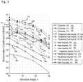
- the HH, VV and HV backscattering coefficients are depicted in Fig. 3 over an elevation angle ⁇ for different road conditions, i.e. for concrete (i.e. dry concrete), weathered wet asphalt, new dry asphalt, weathered dry asphalt and wet concrete.
- the elevation angle ⁇ in Fig. 3 is defined with respect to a normal line of the road surface 21 such that the elevation angle of 75° corresponds to an elevation angle of -15° with respect to a longitudinal axis of the vehicle 11.
- Fig. 3 and the data depicted therein are taken from Giallorenzo, M. et al.: "Radar Backscatter Measurements of Road Surfaces at 77 GHz", 2018 IEEE Antennas and Propagation Society International Symposium, 8-13 July 2018, IEEE, Boston, MA, USA .
- This data has been used as basis for the own investigations according to the disclosure, i.e. for the analysis as depicted in Figs. 4 to 6 and for the decision tree as depicted in Fig. 7 .
- the backscattering coefficients are depicted in units of dBsm (radar cross section in decibels), i.e. on a logarithmic scale including negative values. That is, the "weaker” backscattering coefficients (like the HV backscattering coefficient represented by the curve 24c for dry concrete) are "more negative” than the “stronger” backscattering coefficients (like the VV backscattering coefficient represented by the curve 26b for new asphalt or represented by the curve 27b for weathered asphalt).
- the curves 24a, 24b, 24c represent the HH, VV and HV backscattering coefficients, respectively, for dry concrete.
- the curves 25a, 25b and 25c represent the HH, VV and HV backscattering coefficients, respectively, for weathered wet asphalt
- the curves 26a, 26b, 26c represent the HH, VV and HV backscattering coefficients, respectively, for new asphalt
- the curves 27a, 27b and 27c represent the HH, VV and HV backscattering coefficients, respectively, for weathered dry asphalt.
- the curves 28a and 28b represent the HH and VV backscattering coefficients, respectively, for wet concrete.
- the HV backscattering coefficient has not been available for wet concrete.
- the VV or HH backscattering coefficients are suitable to distinguish concrete and asphalt in general, but they are not suitable to distinguish wet and dry road surfaces. Furthermore, the ratio of the backscattering coefficients (HH/VV) is not suitable to distinguish road surfaces for the used radar frequency of 77 GHz.
- the curves 24c, 25c, 26c and 27c indicate that the HV backscattering coefficient shows the strongest variation with respect to roughness and material of the road surface and with respect to weather conditions, while the VV backscattering coefficient is the least effected, as can be seen by the curves 24a, 25a, 26a, 27a and 28a. Therefore, the difference between the VV and HV backscattering coefficients is expected to be huge and to be suitable for separating different road conditions appropriately.
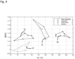
- Fig. 4 This is shown in Fig. 4 , in which the ratio of the HH and VV backscattering coefficients is depicted over the difference between the VV backscattering coefficient and the HV backscattering coefficient.
- the ratio HH/VV clusters in different regions when plotted over VV-HV.
- separate regions can be identified for different road conditions, i.e. a region 31 for wet asphalt, a region 33 for dry asphalt, a region 35 for dry concrete and a region 37 for grass.
- further data for the backscattering coefficient have been taken from Viikari, V. et al.: "Automotive radar technology for detecting road conditions.
- the ratio of the HH backscattering coefficient and the VV backscattering coefficient is used as a function of the difference between the VV backscattering coefficient and the HH backscattering coefficient, as is shown in Fig. 5 .
- a plurality of data points based on the respective radar signals has to be used in order to identify the regions 48, 49 based on respective averages.
- the regions 48, 49 for grass and snow differ from the further regions 41, 43, 45 and 47 for the other road conditions in that for the region 49 representing snow the difference VV-HH is negative, while the ratio HH/VV is smaller than 1, and in that for the region 48 representing grass the difference VV-HH is close to 0, while the ratio HH/VV is close to 1.
- the further regions for the other road conditions overlap, i.e. the region 41 for wet asphalt, the region 43 for dry asphalt, the region 45 for wet concrete and the region 47 for dry concrete.
- the regions 41 and 45 for wet surfaces tend to have widely spread data points, i.e. a high variance
- the regions 43, 47 for dry surfaces tend to have data points clustering in a narrow region, i.e. having a low variance. Therefore, it is possible to distinguish wet and dry road surfaces by analyzing the variance of the ratio HH/VV when plotted over the difference VV-HH.
- one of the cross-polarized backscattering coefficients can additionally be considered, i.e. in addition to the analysis as shown in Fig. 5 , if the HV backscattering coefficient is not available.
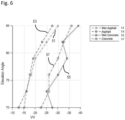
- the relationship of the VV backscattering coefficient and the elevation angle is shown in Fig. 6 .
- the curves 51 and 53 for wet asphalt and dry asphalt, respectively separate from the curves 55 and 57 for wet concrete and dry concrete, respectively, with respect to the VV backscattering coefficient.
- a decision tree is derived for determining road conditions.
- the decision tree is shown in Fig. 7 and represents an embodiment of the method according to the disclosure.
- the radar system 13 is configured to perform the method steps via the processing device 19. The method starts at step 100 where it is determined whether the HV backscattering coefficient is available. In other words, it is determined whether the HV backscattering coefficient is greater than or equal to a cross-polarization threshold.
- the ratio of the HH backscattering coefficient and the VV backscattering coefficient is plotted over the difference between the VV and the HV backscattering coefficients at step 110.
- An example for the step 110 is shown in Fig. 4 .
- thresholds can be defined in order to distinguish e.g. dry and rough road surfaces 130 from smooth and wet road surfaces 140.
- different types or materials of road surfaces can be distinguished as is shown in Fig. 4 .
- the ratio of the HH backscattering coefficient and the VV backscattering coefficient is plotted over the difference between the VV backscattering coefficient and the HH backscattering coefficient at step 120. It is noted that a plurality of respective backscattering coefficients is determined at different elevation angles (see e.g. Fig. 3 and 6 ), the statistical calculations are done for the respective ratio and the respective difference of the backscattering coefficients. An example for the representation of step 120 is shown in Fig. 5 . It is determined at step 121 whether the average of the difference VV-HH is greater than 0 and whether the average of the ratio HH/VV is greater than 1 at the same time.
- step 122 it is determined at step 122 whether the average of the difference VV-HH is equal to or smaller than 0 and whether the average of the ratio HH/VV is equal to or smaller than 1 at the same time.
- the respective averages are calculated based on a plurality of data points derived from the respective radar signals as described above.
- step 121 is valid (i.e. the average of HH/VV is greater than 1 and the average of VV-HH is greater than 0)
- the variance of the data points for the representation of step 120 is determined, i.e. for the data points as shown for example in the regions 41, 43, 45 and 47 of Fig. 5 .
- a large variance is determined (e.g. larger than a variance threshold)
- a wet surface is determined at step 170
- a dry surface is determined at step 180 for a small variance (i.e. smaller than the variance threshold).
- the VV backscattering coefficient is additionally used to determine the type or material of the road surface at step 190.
- An example for this determination is shown in Fig. 6 . That is, a further threshold is defined for the VV backscattering coefficient in order to distinguish the different surface types or different materials of the road at step 200, e.g. asphalt or concrete.
- step 122 is valid (i.e. the average of the ratio HH/VV is close to or smaller than 1 and the average of the difference VV-HH is close to or smaller than 0)
- the averages of the data points for the representation of step 120 is used to distinguish between an irregular rough road, e.g. including gravel or grass, and snow on the road.
- the road condition is determined to include a high irregularity due to vertical objects (e.g. including grass or gravel) at step 220.
- the road condition is determined at step 230 to include snow on the road.
- a plurality of data points is required for performing step 120 and all further steps relying thereon, whereas one single data point is generally sufficient in order to perform steps 110, 130 and 140.
- the decision tree as shown in Fig. 7 requires a low computational effort e.g. in comparison to a support vector machine which is known in the related art for performing similar tasks.
- the radar system 13 (see Fig. 1 ) requires one single radar frequency only, e.g. 77 GHz.
- a machine learning algorithm e.g. a neural network
- Applying a neural network may require that a suitable number of primary input data, i.e. radar returns, has to be available.
- any other procedure may be used for analyzing the backscattering coefficients in an equivalent manner to the method steps as described above, e.g. by implementing a support vector machine.
Landscapes
- Engineering & Computer Science (AREA)
- Radar, Positioning & Navigation (AREA)
- Remote Sensing (AREA)
- Physics & Mathematics (AREA)
- Computer Networks & Wireless Communication (AREA)
- General Physics & Mathematics (AREA)
- Automation & Control Theory (AREA)
- Mathematical Physics (AREA)
- Transportation (AREA)
- Mechanical Engineering (AREA)
- Electromagnetism (AREA)
- Radar Systems Or Details Thereof (AREA)
Priority Applications (3)
| Application Number | Priority Date | Filing Date | Title |
|---|---|---|---|
| EP21197464.7A EP4152040A1 (fr) | 2021-09-17 | 2021-09-17 | Procédé et système de radar permettant de déterminer des conditions routières |
| CN202211070013.7A CN115825956B (zh) | 2021-09-17 | 2022-09-02 | 用于确定道路状况的方法和雷达系统 |
| US17/944,570 US11592522B1 (en) | 2021-09-17 | 2022-09-14 | Method and radar system for determining road conditions |
Applications Claiming Priority (1)
| Application Number | Priority Date | Filing Date | Title |
|---|---|---|---|
| EP21197464.7A EP4152040A1 (fr) | 2021-09-17 | 2021-09-17 | Procédé et système de radar permettant de déterminer des conditions routières |
Publications (1)
| Publication Number | Publication Date |
|---|---|
| EP4152040A1 true EP4152040A1 (fr) | 2023-03-22 |
Family
ID=77838695
Family Applications (1)
| Application Number | Title | Priority Date | Filing Date |
|---|---|---|---|
| EP21197464.7A Pending EP4152040A1 (fr) | 2021-09-17 | 2021-09-17 | Procédé et système de radar permettant de déterminer des conditions routières |
Country Status (3)
| Country | Link |
|---|---|
| US (1) | US11592522B1 (fr) |
| EP (1) | EP4152040A1 (fr) |
| CN (1) | CN115825956B (fr) |
Families Citing this family (1)
| Publication number | Priority date | Publication date | Assignee | Title |
|---|---|---|---|---|
| CN116879866B (zh) * | 2023-09-06 | 2023-11-14 | 四川华腾公路试验检测有限责任公司 | 一种基于激光雷达三维数据的路面平整度评价方法 |
Citations (2)
| Publication number | Priority date | Publication date | Assignee | Title |
|---|---|---|---|---|
| EP2653882A1 (fr) * | 2008-09-11 | 2013-10-23 | Teknologian Tutkimuskeskus VTT | Procédé de reconnaissance de condition routière |
| US20170168156A1 (en) * | 2014-02-12 | 2017-06-15 | Jaguar Land Rover Limited | System for use in a vehicle |
Family Cites Families (25)
| Publication number | Priority date | Publication date | Assignee | Title |
|---|---|---|---|---|
| US4107678A (en) * | 1976-09-28 | 1978-08-15 | Westinghouse Electric Corp. | Polarization correlation target seeker |
| JP4120114B2 (ja) * | 1999-11-04 | 2008-07-16 | 株式会社デンソー | 路面状況推定装置 |
| US6404377B1 (en) * | 2000-10-31 | 2002-06-11 | Raytheon Company | UHF foliage penetration radar antenna |
| US6967612B1 (en) * | 2004-10-22 | 2005-11-22 | Gorman John D | System and method for standoff detection of human carried explosives |
| US9063230B2 (en) * | 2008-10-08 | 2015-06-23 | Delphi Technologies, Inc. | Radar sensor module |
| EP2821810B1 (fr) * | 2012-03-01 | 2019-09-04 | Nissan Motor Co., Ltd | Détecteur de véhicule et procédé de détection de véhicule |
| CN104520735B (zh) * | 2012-08-08 | 2016-03-02 | 日产自动车株式会社 | 路面状态检测装置以及路面状态检测方法 |
| CN104768822B (zh) * | 2012-09-20 | 2017-04-19 | 谷歌公司 | 检测公路天气状况的方法和系统 |
| US9293812B2 (en) * | 2013-11-06 | 2016-03-22 | Delphi Technologies, Inc. | Radar antenna assembly |
| GB2523091B (en) * | 2014-02-12 | 2017-11-01 | Jaguar Land Rover Ltd | A system for use in a vehicle |
| DE102015003115B4 (de) * | 2015-03-11 | 2021-10-07 | Audi Ag | Verfahren zur Ermittlung einer Fahrbahnzustandsinformation und Kraftfahrzeug |
| US10360459B2 (en) * | 2016-04-06 | 2019-07-23 | Panasonic Intellectual Property Management Co., Ltd. | Detection device, detection method, and non-transitory computer-readable recording medium storing detection program |
| GB2552027B (en) * | 2016-07-08 | 2019-02-20 | Jaguar Land Rover Ltd | A vehicle system for determining terrain type |
| LU93302B1 (en) * | 2016-11-14 | 2018-06-18 | Iee Sa | Polarimetric Radar System and Method for Classifying Objects ahead of a Vehicle |
| LU93324B1 (en) * | 2016-11-25 | 2018-05-25 | Iee Sa | Polarimetric Radar System and Method for Detecting and Classifying Vehicle Occupants and Other Objects in a Vehicle Interior |
| RU2660977C2 (ru) * | 2016-11-30 | 2018-07-11 | Общество С Ограниченной Ответственностью "Инновационный Центр Самоцвет" (Ооо "Иц Самоцвет") | Способ обеспечения курсовой устойчивости и безопасности автомобиля и устройство для его осуществления |
| LU93431B1 (en) * | 2016-12-27 | 2018-06-28 | Iee Sa | Polarimetric Radar System and Method for Object Classification and Road Condition Estimation in Stationary Applications |
| KR102550832B1 (ko) * | 2017-02-24 | 2023-07-03 | 아스틱스 게엠베하 | 편광측정 레이더 데이터를 이용한 물체 분류 방법 및 그에 적합한 장치 |
| DE102017223471A1 (de) * | 2017-12-20 | 2019-06-27 | Robert Bosch Gmbh | Vorrichtung zum Aussenden und Empfangen elektromagnetischer Strahlung |
| DE102018201620B4 (de) * | 2018-02-02 | 2024-05-02 | Continental Autonomous Mobility Germany GmbH | Vorrichtung und Verfahren zum Radar-basierten Klassifizieren von Fahrbahnzuständen |
| US10877150B2 (en) * | 2018-03-06 | 2020-12-29 | Honeywell International Inc. | Ice crystal detection by weather radar |
| DE102018203924A1 (de) * | 2018-03-15 | 2019-09-19 | Robert Bosch Gmbh | Verfahren und Vorrichtung zur Erkennung einer Fahrbahnoberflächenbeschaffenheit |
| JP7174668B2 (ja) * | 2019-04-25 | 2022-11-17 | 京セラ株式会社 | 電子機器、電子機器の制御方法、及び電子機器の制御プログラム |
| EP3862773A1 (fr) * | 2020-02-04 | 2021-08-11 | Aptiv Technologies Limited | Dispositif de radar |
| EP4376220A3 (fr) * | 2020-02-04 | 2024-07-31 | Aptiv Technologies AG | Dispositif radar |
-
2021
- 2021-09-17 EP EP21197464.7A patent/EP4152040A1/fr active Pending
-
2022
- 2022-09-02 CN CN202211070013.7A patent/CN115825956B/zh active Active
- 2022-09-14 US US17/944,570 patent/US11592522B1/en active Active
Patent Citations (2)
| Publication number | Priority date | Publication date | Assignee | Title |
|---|---|---|---|---|
| EP2653882A1 (fr) * | 2008-09-11 | 2013-10-23 | Teknologian Tutkimuskeskus VTT | Procédé de reconnaissance de condition routière |
| US20170168156A1 (en) * | 2014-02-12 | 2017-06-15 | Jaguar Land Rover Limited | System for use in a vehicle |
Non-Patent Citations (4)
| Title |
|---|
| BYSTROV ALEKSANDR ET AL: "Analysis of classification algorithms applied to road surface recognition", 2015 IEEE RADAR CONFERENCE (RADARCON), IEEE, 10 May 2015 (2015-05-10), pages 907 - 911, XP032788423, DOI: 10.1109/RADAR.2015.7131124 * |
| GIALLORENZO, M. ET AL.: "2018 IEEE Antennas and Propagation Society International Symposium", 8 July 2018, IEEE, article "Radar Backscatter Measurements of Road Surfaces at 77 GHz" |
| TRUMMER STEFAN ET AL: "Autonomous Driving Features based on 79 GHz Polarimetric Radar Data", 2018 15TH EUROPEAN RADAR CONFERENCE (EURAD), EUROPEAN MICROWAVE ASSOCIATION, 26 September 2018 (2018-09-26), pages 18 - 21, XP033453479, DOI: 10.23919/EURAD.2018.8546632 * |
| VIIKARI, V. ET AL.: "2008 European Radar Conference", 30 October 2008, IEEE, article "Automotive radar technology for detecting road conditions. Backscattering properties of dry, wet, and icy asphalt" |
Also Published As
| Publication number | Publication date |
|---|---|
| US20230087328A1 (en) | 2023-03-23 |
| CN115825956A (zh) | 2023-03-21 |
| US11592522B1 (en) | 2023-02-28 |
| CN115825956B (zh) | 2023-12-29 |
Similar Documents
| Publication | Publication Date | Title |
|---|---|---|
| US20220187415A1 (en) | Method for object classification using polarimetric radar data and device suitable therefor | |
| US9575170B2 (en) | Radar device and target height calculation method | |
| KR102488038B1 (ko) | 차량용 레이더 장치 및 그의 타겟 결정 방법 | |
| US10048355B2 (en) | Method and radar apparatus for detecting target object | |
| US8477063B2 (en) | System and method for obstacle detection and warning | |
| US6954172B2 (en) | Power monitor for radar system | |
| US10473760B2 (en) | Radar device and vertical axis-misalignment detecting method | |
| CN109752699B (zh) | 基于距离-啁啾图中曲线检测的目标检测 | |
| US11592522B1 (en) | Method and radar system for determining road conditions | |
| US9291659B2 (en) | Antenna blockage detection | |
| US10495743B2 (en) | Direction error detection method and apparatus using estimated directions, and in-vehicle radar apparatus | |
| KR101538368B1 (ko) | 엑스밴드 이중편파 레이더 원시자료를 이용한 강수체 구분 방법 | |
| Bystrov et al. | Experimental study of rough surface backscattering for low terahertz automotive radar | |
| CN107076831A (zh) | 雷达传感器 | |
| EP0724166B1 (fr) | Méthode et dispositif d'estimation de la polarisation d'un signal radar | |
| RU2449309C1 (ru) | Способ распознавания класса цели и устройство для его осуществления | |
| CA3055712A1 (fr) | Dispositif de detection de cible et procede de detection de cible | |
| US11454705B2 (en) | Tracking system and method for characterizing target height using percentage of range bins | |
| US12025695B2 (en) | Electronic device, method for controlling electronic device, and electronic device control program | |
| Averyanova | Statistical algorithm for turbulence detection using polarization features of radar reflections from rain | |
| KR20170054168A (ko) | 레이더 시스템의 씨파를 기반으로 하는 신호 처리 방법 및 그 장치 | |
| Yamada et al. | Radar cross section measurement of road debris in 79 GHz-band | |
| KR102618612B1 (ko) | 개선된 근거리 탐지용 신호처리 기능을 포함하는 fmcw레이더 장치 | |
| US20240255613A1 (en) | Sensor blockage detection based upon raw radar data | |
| Zaumseil et al. | Radar-based near field environment perception using back projection algorithm |
Legal Events
| Date | Code | Title | Description |
|---|---|---|---|
| PUAI | Public reference made under article 153(3) epc to a published international application that has entered the european phase |
Free format text: ORIGINAL CODE: 0009012 |
|
| STAA | Information on the status of an ep patent application or granted ep patent |
Free format text: STATUS: THE APPLICATION HAS BEEN PUBLISHED |
|
| AK | Designated contracting states |
Kind code of ref document: A1 Designated state(s): AL AT BE BG CH CY CZ DE DK EE ES FI FR GB GR HR HU IE IS IT LI LT LU LV MC MK MT NL NO PL PT RO RS SE SI SK SM TR |
|
| STAA | Information on the status of an ep patent application or granted ep patent |
Free format text: STATUS: REQUEST FOR EXAMINATION WAS MADE |
|
| 17P | Request for examination filed |
Effective date: 20230921 |
|
| RBV | Designated contracting states (corrected) |
Designated state(s): AL AT BE BG CH CY CZ DE DK EE ES FI FR GB GR HR HU IE IS IT LI LT LU LV MC MK MT NL NO PL PT RO RS SE SI SK SM TR |
|
| RAP1 | Party data changed (applicant data changed or rights of an application transferred) |
Owner name: APTIV TECHNOLOGIES AG |