EP4152006A1 - Automatic analysis device and method for inserting reaction container - Google Patents
Automatic analysis device and method for inserting reaction container Download PDFInfo
- Publication number
- EP4152006A1 EP4152006A1 EP21802189.7A EP21802189A EP4152006A1 EP 4152006 A1 EP4152006 A1 EP 4152006A1 EP 21802189 A EP21802189 A EP 21802189A EP 4152006 A1 EP4152006 A1 EP 4152006A1
- Authority
- EP
- European Patent Office
- Prior art keywords
- hole
- reaction container
- incubator
- automatic analyzer
- lubricating member
- Prior art date
- Legal status (The legal status is an assumption and is not a legal conclusion. Google has not performed a legal analysis and makes no representation as to the accuracy of the status listed.)
- Granted
Links
Images




Classifications
-
- G—PHYSICS
- G01—MEASURING; TESTING
- G01N—INVESTIGATING OR ANALYSING MATERIALS BY DETERMINING THEIR CHEMICAL OR PHYSICAL PROPERTIES
- G01N35/00—Automatic analysis not limited to methods or materials provided for in any single one of groups G01N1/00 - G01N33/00; Handling materials therefor
-
- G—PHYSICS
- G01—MEASURING; TESTING
- G01N—INVESTIGATING OR ANALYSING MATERIALS BY DETERMINING THEIR CHEMICAL OR PHYSICAL PROPERTIES
- G01N35/00—Automatic analysis not limited to methods or materials provided for in any single one of groups G01N1/00 - G01N33/00; Handling materials therefor
- G01N35/02—Automatic analysis not limited to methods or materials provided for in any single one of groups G01N1/00 - G01N33/00; Handling materials therefor using a plurality of sample containers moved by a conveyor system past one or more treatment or analysis stations
- G01N35/026—Automatic analysis not limited to methods or materials provided for in any single one of groups G01N1/00 - G01N33/00; Handling materials therefor using a plurality of sample containers moved by a conveyor system past one or more treatment or analysis stations having blocks or racks of reaction cells or cuvettes
-
- G—PHYSICS
- G01—MEASURING; TESTING
- G01N—INVESTIGATING OR ANALYSING MATERIALS BY DETERMINING THEIR CHEMICAL OR PHYSICAL PROPERTIES
- G01N35/00—Automatic analysis not limited to methods or materials provided for in any single one of groups G01N1/00 - G01N33/00; Handling materials therefor
- G01N35/0099—Automatic analysis not limited to methods or materials provided for in any single one of groups G01N1/00 - G01N33/00; Handling materials therefor comprising robots or similar manipulators
-
- G—PHYSICS
- G01—MEASURING; TESTING
- G01N—INVESTIGATING OR ANALYSING MATERIALS BY DETERMINING THEIR CHEMICAL OR PHYSICAL PROPERTIES
- G01N35/00—Automatic analysis not limited to methods or materials provided for in any single one of groups G01N1/00 - G01N33/00; Handling materials therefor
- G01N35/02—Automatic analysis not limited to methods or materials provided for in any single one of groups G01N1/00 - G01N33/00; Handling materials therefor using a plurality of sample containers moved by a conveyor system past one or more treatment or analysis stations
- G01N35/025—Automatic analysis not limited to methods or materials provided for in any single one of groups G01N1/00 - G01N33/00; Handling materials therefor using a plurality of sample containers moved by a conveyor system past one or more treatment or analysis stations having a carousel or turntable for reaction cells or cuvettes
-
- G—PHYSICS
- G01—MEASURING; TESTING
- G01N—INVESTIGATING OR ANALYSING MATERIALS BY DETERMINING THEIR CHEMICAL OR PHYSICAL PROPERTIES
- G01N35/00—Automatic analysis not limited to methods or materials provided for in any single one of groups G01N1/00 - G01N33/00; Handling materials therefor
- G01N35/02—Automatic analysis not limited to methods or materials provided for in any single one of groups G01N1/00 - G01N33/00; Handling materials therefor using a plurality of sample containers moved by a conveyor system past one or more treatment or analysis stations
- G01N35/04—Details of the conveyor system
-
- G—PHYSICS
- G01—MEASURING; TESTING
- G01N—INVESTIGATING OR ANALYSING MATERIALS BY DETERMINING THEIR CHEMICAL OR PHYSICAL PROPERTIES
- G01N35/00—Automatic analysis not limited to methods or materials provided for in any single one of groups G01N1/00 - G01N33/00; Handling materials therefor
- G01N35/10—Devices for transferring samples or any liquids to, in, or from, the analysis apparatus, e.g. suction devices, injection devices
- G01N35/1002—Reagent dispensers
-
- G—PHYSICS
- G01—MEASURING; TESTING
- G01N—INVESTIGATING OR ANALYSING MATERIALS BY DETERMINING THEIR CHEMICAL OR PHYSICAL PROPERTIES
- G01N35/00—Automatic analysis not limited to methods or materials provided for in any single one of groups G01N1/00 - G01N33/00; Handling materials therefor
- G01N35/10—Devices for transferring samples or any liquids to, in, or from, the analysis apparatus, e.g. suction devices, injection devices
- G01N35/1009—Characterised by arrangements for controlling the aspiration or dispense of liquids
- G01N35/1011—Control of the position or alignment of the transfer device
-
- G—PHYSICS
- G01—MEASURING; TESTING
- G01N—INVESTIGATING OR ANALYSING MATERIALS BY DETERMINING THEIR CHEMICAL OR PHYSICAL PROPERTIES
- G01N35/00—Automatic analysis not limited to methods or materials provided for in any single one of groups G01N1/00 - G01N33/00; Handling materials therefor
- G01N2035/00178—Special arrangements of analysers
- G01N2035/00277—Special precautions to avoid contamination (e.g. enclosures, glove- boxes, sealed sample carriers, disposal of contaminated material)
-
- G—PHYSICS
- G01—MEASURING; TESTING
- G01N—INVESTIGATING OR ANALYSING MATERIALS BY DETERMINING THEIR CHEMICAL OR PHYSICAL PROPERTIES
- G01N35/00—Automatic analysis not limited to methods or materials provided for in any single one of groups G01N1/00 - G01N33/00; Handling materials therefor
- G01N2035/00346—Heating or cooling arrangements
- G01N2035/00356—Holding samples at elevated temperature (incubation)
-
- G—PHYSICS
- G01—MEASURING; TESTING
- G01N—INVESTIGATING OR ANALYSING MATERIALS BY DETERMINING THEIR CHEMICAL OR PHYSICAL PROPERTIES
- G01N35/00—Automatic analysis not limited to methods or materials provided for in any single one of groups G01N1/00 - G01N33/00; Handling materials therefor
- G01N35/02—Automatic analysis not limited to methods or materials provided for in any single one of groups G01N1/00 - G01N33/00; Handling materials therefor using a plurality of sample containers moved by a conveyor system past one or more treatment or analysis stations
- G01N35/04—Details of the conveyor system
- G01N2035/0401—Sample carriers, cuvettes or reaction vessels
- G01N2035/0406—Individual bottles or tubes
-
- G—PHYSICS
- G01—MEASURING; TESTING
- G01N—INVESTIGATING OR ANALYSING MATERIALS BY DETERMINING THEIR CHEMICAL OR PHYSICAL PROPERTIES
- G01N35/00—Automatic analysis not limited to methods or materials provided for in any single one of groups G01N1/00 - G01N33/00; Handling materials therefor
- G01N35/02—Automatic analysis not limited to methods or materials provided for in any single one of groups G01N1/00 - G01N33/00; Handling materials therefor using a plurality of sample containers moved by a conveyor system past one or more treatment or analysis stations
- G01N35/04—Details of the conveyor system
- G01N2035/0439—Rotary sample carriers, i.e. carousels
- G01N2035/0446—Combinations of the above
-
- G—PHYSICS
- G01—MEASURING; TESTING
- G01N—INVESTIGATING OR ANALYSING MATERIALS BY DETERMINING THEIR CHEMICAL OR PHYSICAL PROPERTIES
- G01N35/00—Automatic analysis not limited to methods or materials provided for in any single one of groups G01N1/00 - G01N33/00; Handling materials therefor
- G01N35/02—Automatic analysis not limited to methods or materials provided for in any single one of groups G01N1/00 - G01N33/00; Handling materials therefor using a plurality of sample containers moved by a conveyor system past one or more treatment or analysis stations
- G01N35/04—Details of the conveyor system
- G01N2035/046—General conveyor features
- G01N2035/0462—Buffers [FIFO] or stacks [LIFO] for holding carriers between operations
- G01N2035/0463—Buffers [FIFO] or stacks [LIFO] for holding carriers between operations in incubators
Definitions
- the present invention relates to an automatic analyzer.
- An automatic analyzer is a device that analyzes specific components included in a sample such as blood or urine supplied from a patient, and is used in hospitals and inspection facilities. Prior to analyzing specific components in a sample, in an incubator, a mixed solution mixed with a sample and a reagent is reacted at a predetermined temperature, close to a human temperature of 37°C, for example.
- Patent Literature 1 discloses an insulation made of polyethylene is mounted on an incubator at places other than the vicinity of a hole into which a reaction vessel in a tapered shape is inserted.
- Patent Literature 1 International Publication No. WO2018/147029
- Patent Literature 1 no consideration is paid to the insertion of a reaction vessel, specifically a reaction vessel in a tubular shape into a hole of the incubator.
- the reaction vessel in a tubular shape can reduce the liquid amount of a sample of the reaction vessel in a tapered shape, the resistance at the time of insertion into the hole of the incubator.
- the increase in resistance at the time of insertion sometimes makes the mounting of the reaction vessel into the incubator, and the processing performance of the automatic analyzer is sometimes reduced.
- an object of the present invention to provide an automatic analyzer that is capable of smoothly inserting a reaction vessel into the hole of the incubator.
- the present invention is an automatic analyzer, including an incubator having a hole into which a reaction vessel containing a mixture of a sample and a reagent is to be inserted, and a transfer unit configured to transfer an unused reaction vessel to the incubator and insert the reaction vessel into the hole.
- a lubricating member having a self-lubricating property is provided at an inlet port of the hole.
- an automatic analyzer that is capable of smoothly inserting a reaction vessel into the hole of the incubator.
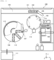
- the automatic analyzer 100 has a sample transport path 103, a reagent disk 104, a transfer unit 109, an incubator 105, a spectrophotometer 115, and a control unit 111.
- the components will be described.
- the lateral direction in Fig. 1 is defined as an X-axis
- the vertical direction is defined as a Y-axis
- the vertical direction that is a direction orthogonal to the paper surface is defined as a Z-axis.
- the sample transport path 103 transports a sample rack 102 on which a plurality of sample containers 101 containing a sample is mounted to a position accessible by a sample dispensing unit 106.
- the sample contained in the sample container 101 is dispensed into a reaction vessel 114 retained in the incubator 105 by the sample dispensing unit 106.
- the transfer unit 109 grasps and transfers the reaction vessel 114 or a dispensing chip, which is a consumable item disposed in a tray with a gripper.
- the reaction vessel 114 to be transferred from the tray to the incubator 105 using the transfer unit 109 is used for containing a mixed solution of the sample and a reagent is replaced in every analysis. That is, the transfer unit 109 transfers an unused reaction vessel 114 to the incubator 105.
- the reagent disk 104 keeps a plurality of reagent containers 112 containing the reagent. In order to mitigate the degradation of the reagent, the inside of the reagent disk 104 is kept at a temperature lower than room temperature. Moreover, the reagent disk 104 is covered with a reagent disk cover 113. Note that in Fig. 1 , in order to represent a disposition example of the reagent container 112, only a part of the reagent disk cover 113 is shown. The reagent contained in the reagent container 112 is dispensed into the reaction vessel 114 into which the sample is dispensed by the reagent dispensing unit 107.
- the incubator 105 retains a plurality of reaction vessels 114 containing the mixed solution of the sample and the reagent, and is kept at a predetermined temperature of 37°C, for example, in order to react the mixed solution.
- the mixed solution is reacted for a predetermined time period in the process of retaining the reaction vessel 114 in the incubator 105 whose temperature is kept at a predetermined temperature, and thus the mixed solution is turned into a reaction solution used for analysis.
- the spectrophotometer 115 measures the absorbance of the reaction solution in order to analyzes specific components included in the reaction solution contained in the reaction vessel 114.
- the spectrophotometer 115 is disposed adjacent to the incubator 105, and has a light source, a spectral element, and a photodetector.
- a light source a halogen lamp is used, for the spectral element, a diffraction grating is used, and for the photodetector, a photomultiplier tube, a photodiode, or the like is used.
- a light beam emitted from the light source is separated into measurement wavelengths by the spectral element, and then applied to the reaction solution contained in the reaction vessel 114, and is detected by the intensity of the light beam transmitted through the reaction solution.
- An absorbance A ⁇ relating to a certain wavelength ⁇ is calculated by the following formula using an intensity I ⁇ 0 of a light beam applied to the reaction solution and the intensity of the light beam transmitted through the reaction solution I ⁇ .
- a ⁇ log I ⁇ 0 / I ⁇
- the absorbance A ⁇ is proportional to an optical path length L and a concentration C of a specific component included in the reaction solution, the following formula is held.
- a ⁇ ⁇ • L • C
- ⁇ is a proportionality constant determined for every type of specific component. That is, the concentration C of the specific component is calculated from the value of the absorbance A ⁇ calculated from the intensity I ⁇ of the transmitted light beam of the reaction solution and the optical path length L.
- the control unit 111 is a device that controls the operation of the components, accepts inputs of data necessary for analyzes, displays or stores results of analysis, which is, for example, a computer.
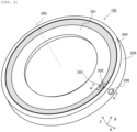
- the incubator 105 in Fig. 2 has a board 201 in a ring shape that rotates at a predetermined angle every lapse of a predetermined time period at a central axis 200 as a rotation axis, a heater 204, and an insulation 205.
- the components will be described.
- the radial direction of the board 201 is defined as an R axis
- the circumferential direction is defined as a ⁇ axis
- the vertical direction that is a direction in parallel with the central axis 200 is defined as a Z-axis.
- the board 201 has a plurality of holes 202 into which the reaction vessel 114 is inserted along the outer periphery. Note that in Fig. 2 , in order to simplify the drawing, only one hole 202 is shown.
- the inlet ports of the individual holes 202 are provided with a lubricating member 203 that is a member having self lubricity.
- the self lubricity means that the coefficient of friction of the material itself is extremely small.
- the lubricating member 203 is a material having a coefficient of friction smaller than the coefficient of friction of at least the board 201, which is PTFE (Poly Tetra FluoroEthylene), polyacetal, ultrahigh molecular polyethylene, monomer-cast nylon, and the like, for example.
- the lubricating member 203 is provided on the inlet port of the hole 202, and thus the reaction vessel 114 can be smoothly inserted into the hole 202.
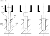
- the gripper of the transfer unit 109 releases the grasp of the reaction vessel after the reaction vessel is deeply pressed by a predetermined distance from the opening of the hole 202. It should be noted that although the gripper desirably vertically brings down the reaction vessel 114 from right above the hole 202, the grasp may be released after the reaction vessel 114 is intentionally brought into contact with the lubricating member 203.
- the heater 204 is a hating resistor in a belt shape that is disposed so as to cover the side surface of the outer periphery of the board 201, and the supply of electric power is controlled based on the measured value of a thermometer, not shown, provided on the board 201.
- the insulation 205 is a material having a relatively low coefficient of thermal conductivity, and the insulation 205 is disposed so as to cover the outer periphery of the heater 204 and the bottom surface of the board 201.
- the board 201 is kept at a predetermined temperature by the heating of the heater 204 and the insulation of the insulation 205, the reaction of the mixed solution in the reaction vessel 114 inserted into the hole 202 progresses, and the reaction solution is generated.
- a photometric hole 206 is provided, and is used for measuring the absorbance of the reaction solution of the spectrophotometer 115.
- the photometric hole 206 may be provided for every hole 202 to be inserted into the reaction vessel 114, or may be provided at every several holes 202, for example, at every one hole 202.
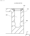
- the lubricating member 203 is a resin material such as PTFE, and has a relatively low coefficient of thermal conductivity, the lubricating member 203 is disposed on the inlet port of the hole 202 so as not to inhibit heat transfer from the board 201 to the reaction vessel 114. Specifically, the lubricating member 203 is preferably provided at a position higher than the liquid level of at least the mixed solution so as not to inhibit heat transfer of the mixed solution contained in the reaction vessel 114.
- the photometric hole 206 is provided such that the inner periphery side communicates with the outer periphery side in the radial direction of the incubator 105 through the hole 202. That is, a light beam emitted from the light source and separated by the spectral element is applied to the reaction solution contained in the reaction vessel 114 through any one of the photometric holes 206, and the light beam transmitted through the reaction solution is detected by the photodetector through the other photometric hole 206.
- Fig. 5 shows a side view of the reaction vessel 114 seen from the R direction and a B-B cross sectional view of the side view.
- the reaction vessel 114 in Fig. 5 has a protrusion 501 and two translucent surfaces 502, and places other than the places at which the protrusion 501 and the translucent surface 502 are provided are in a tubular shape. That is, most of the reaction vessel 114 is in a tubular shape.
- the two translucent surfaces 502 are in parallel with each other, one is a surface into which the separated light beam enters, and the other is a surface through which the transmitted light beam of the reaction solution passes.
- the reaction vessel 114 inserted into the hole 202 is disposed such that the translucent surface 502 faces the photometric hole 206.
- a distance between the two translucent surfaces 502 is the optical path length L.
- the protrusion 501 is a portion protruding from the side surface of the reaction vessel 114, and is provided so as to have a predetermined angle to the translucent surface 502 about the central axis of the reaction vessel 114 in parallel with each other the Z-axis.
- the angle of the protrusion 501 to the translucent surface 502 is 0° such that the protrusion 501 is in parallel with each other the translucent surface 502.
- the reaction vessel in a tapered shape an reduce the liquid amount of the sample necessary for analysis as the angle formed of the vertical axis and the side surface is reduced, and when the formed angle is at 0°, i.e., when the reaction vessel 114 is in a tubular shape, the minimum liquid amount is achieved.
- the formed angle is reduced, the resistance when the reaction vessel 114 is inserted into the hole 202 of the incubator 105 increases. The increase in resistance at the time of insertion makes the mounting of the reaction vessel 114 on the incubator 105 is uncertain, sometimes leading to the degradation of the processing performance of the automatic analyzer 100.
- the reaction vessel 114 is smoothly inserted into the hole 202, and it is possible to maintain the processing performance of the automatic analyzer 100.
- Fig. 6 shows a plan view of the lubricating member 203 seen from the Z-direction, a C-C cross sectional view of the plan view, and a perspective view of the lubricating member 203.
- the lubricating member 203 in Fig. 6 has an opening through which the reaction vessel 114 passes, a cylindrical portion 601, a claw 602, a chamfering portion 603, and a guide groove 604.
- the cylindrical portion 601 is a portion having a tubular shape that is fit into the top end of the hole 202 in order to position the lubricating member 203 to the hole 202. That is, the outer diameter of the cylindrical portion 601 nearly matches the inner diameter of the top end of the hole 202.
- the claw 602 is a portion that engages with the incubator 105 in order to prevent the lubricating member 203 having self lubricity from falling off from the incubator 105. That is, since there is the case in which the lubricating member 203 that is slippery to the incubator 105 falls off even though the reaction vessel 114 slightly touches the lubricating member 203, the incubator 105 engages with the claw 602, and thus the lubricating member 203 is prevented from falling off.
- the chamfering portion 603 is an inclined plane provided on the edge of the opening of the lubricating member 203 whose side of the hole 202 is low, in order to mitigate the resistance when the reaction vessel 114 is inserted into the lubricating member 203. Note that since the coefficient of friction of the lubricating member 203 having self lubricity is extremely small, the chamfering portion 603 does not necessarily have to be provided.
- the directional portion represents a site having a function that directs the translucent surface 502 of the reaction vessel 114 to a predetermined direction.
- the guide groove 604 as an example of the directional portion is a groove having a function of facing the translucent surface 502 to the photometric hole 206, into which the protrusion 501 is fit. That is, in the case in which the angle of the protrusion 501 to the translucent surface 502 is 0°, the guide groove 604 is provided along the circumferential direction of the incubator 105.
- the guide groove 604 has a Y-groove shape. Even though the protrusion 501 is displaced more or less to the guide groove 604, the displacement is corrected along the Y-groove as shown in Fig. 7 , and the positioning accuracy of the reaction vessel 114 is reserved.
- the directional portion is not limited to the guide groove 604.
- the site corresponding to the guide groove 604 may be formed in a projecting shape, and the site corresponding to the protrusion 501 may be formed in a recessed shape.
- the reaction vessel 114 inserted into the incubator 105 mounted on the lubricating member 203 will be described.
- the angle of the protrusion 501 to the translucent surface 502 of the reaction vessel 114 is 0°
- the guide groove 604 of the lubricating member 203 is provided along the circumferential direction of the incubator 105.
- the protrusion 501 of the reaction vessel 114 is fit into the guide groove 604 of the lubricating member 203, the translucent surface 502 of the reaction vessel 114 then faces the photometric hole 206, and becomes vertical to an optical path axis 801 of the spectrophotometer 115.
- the incubator 105 in Fig. 10 has an inter-hole groove 1001 along the circumferential direction between the adjacent holes 202.
- the inter-hole groove 1001 is provided in parallel with the guide groove 604 of the lubricating member 203, and into which the protrusion 501 of the reaction vessel 114 is fit.
- the protrusion 501 of the reaction vessel 114 is fit into the inter-hole groove 1001 as well as into the guide groove 604 to increase the contact area of the protrusion 501, leading to resistance to rotation of the reaction vessel 114, and the translucent surface 502 is easily vertically aligned with the optical path axis 801 of the spectrophotometer 115. Moreover, since the inter-hole groove 1001 is provided concentrically with the board 201 of the incubator 105.
- the reaction vessel 114 is smoothly inserted into the hole 202.
- Such smooth insertion surely mounts the reaction vessel 114 on the incubator 105, and thus it is possible to maintain the processing performance of the automatic analyzer 100.
- the automatic analyzer 100 for biochemical testing has been described.
- an automatic analyzer 100 for immunologic testing using antigen antibody reactions shown in Fig. 11 will be described. Note that differences from the first embodiment are in that configurations involved in analysis and a pre-wash unit 108 and an analysis unit 110 are provided instead of the spectrophotometer 115.
- the pre-wash unit 108 is a device that separates components unnecessary for analysis from a reaction solution.
- a reagent including magnetic fine particles attached with an antibody is used, and an antigen, which is a measured substance in a sample, bonds with the antibody attached to the magnetic fine particles by an immune reaction in an incubator 105.
- a reaction vessel 114 containing the reaction solution after the immune reaction is transferred to the pre-wash unit 108, and a component that does not bond with the magnetic fine particles, i.e., a component unnecessary for analysis is separated using a magnetic field.
- the reaction vessel 114 in which the unnecessary component is separated is returned to the incubator 105, transported to a position at which the analysis unit 110 is accessible by the rotation of the incubator 105, and then transferred to the analysis unit 110.
- the analysis unit 110 analyzes the reaction solution from which unnecessary components contained in the transferred reaction vessel 114 is separated.
- the analysis unit 110 has a light source, a spectral element, and a photodetector, and has a function that adjusts temperatures in order to maintain the reproducibility of analysis.
- the reaction vessel 114 containing the reaction solution to be analyzed is transferred from the incubator 105 to the analysis unit 110, and then analyzed by the analysis unit 110.
- the incubator 105 of the present embodiment since a lubricating member 203 having self lubricity is provided at the inlet port of a hole 202, the reaction vessel 114 is smoothly inserted into the hole 202.
- the incubator 105 of the present embodiment may include or not include a photometric hole 206.
- two protrusions 501 may be provided.
- the two guide grooves 604 and the two protrusions 501 may be provided at opposite positions, or may be provided with a given angle difference.
- the first protrusion and the second protrusion may have different shapes.
- one protrusion 501 may be provided, and the numbers of the guide grooves 604 and the protrusions 501 do not necessarily have to be the same.
- the number of the guide grooves 604 is not limited in the range in which the guide grooves 604 can be provided at the hole 202, as long as the numbers of the guide grooves 604 is equal to or more than the number of the protrusions 501.
- the present invention is not limited to the foregoing embodiments, and may be modified in the scope not deviating from the gist of the invention.
- the shape of the incubator 105 may be in a ring shape as shown in Fig. 2 , or may be in a shape in which the reaction vessels 114 are linearly arranged.
- a plurality of components disclosed in the foregoing embodiments may be appropriately combined.
- some components may be removed from all the components shown in the foregoing embodiments.
Landscapes
- Chemical & Material Sciences (AREA)
- General Health & Medical Sciences (AREA)
- Life Sciences & Earth Sciences (AREA)
- Health & Medical Sciences (AREA)
- Analytical Chemistry (AREA)
- Biochemistry (AREA)
- Physics & Mathematics (AREA)
- General Physics & Mathematics (AREA)
- Immunology (AREA)
- Pathology (AREA)
- Chemical Kinetics & Catalysis (AREA)
- Engineering & Computer Science (AREA)
- Robotics (AREA)
- Automatic Analysis And Handling Materials Therefor (AREA)
Abstract
Description
- The present invention relates to an automatic analyzer.
- An automatic analyzer is a device that analyzes specific components included in a sample such as blood or urine supplied from a patient, and is used in hospitals and inspection facilities. Prior to analyzing specific components in a sample, in an incubator, a mixed solution mixed with a sample and a reagent is reacted at a predetermined temperature, close to a human temperature of 37°C, for example.
- Patent Literature 1 discloses an insulation made of polyethylene is mounted on an incubator at places other than the vicinity of a hole into which a reaction vessel in a tapered shape is inserted.
- Patent Literature 1: International Publication No.
WO2018/147029 - However, in Patent Literature 1, no consideration is paid to the insertion of a reaction vessel, specifically a reaction vessel in a tubular shape into a hole of the incubator. Although the reaction vessel in a tubular shape can reduce the liquid amount of a sample of the reaction vessel in a tapered shape, the resistance at the time of insertion into the hole of the incubator. The increase in resistance at the time of insertion sometimes makes the mounting of the reaction vessel into the incubator, and the processing performance of the automatic analyzer is sometimes reduced.
- Therefore, it is an object of the present invention to provide an automatic analyzer that is capable of smoothly inserting a reaction vessel into the hole of the incubator.
- In order to achieve the object, the present invention is an automatic analyzer, including an incubator having a hole into which a reaction vessel containing a mixture of a sample and a reagent is to be inserted, and a transfer unit configured to transfer an unused reaction vessel to the incubator and insert the reaction vessel into the hole. In the automatic analyzer, a lubricating member having a self-lubricating property is provided at an inlet port of the hole.
- According to the present invention, it is possible to provide an automatic analyzer that is capable of smoothly inserting a reaction vessel into the hole of the incubator.
-
- [
FIG. 1] FIG. 1 is a plan view showing a schematic configuration of an example of an automatic analyzer for biochemical examination. - [
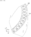
FIG. 2] FIG. 2 is a perspective view showing an example of an incubator. - [
FIG. 3] FIG. 3 is a diagram showing a state in which a reaction container is inserted into a hole. - [
FIG. 4] FIG. 4 is a diagram showing an A-A cross section ofFIG. 2 . - [
FIG. 5] FIG. 5 is a diagram showing an example of the reaction container. - [
FIG. 6] FIG. 6 is a diagram showing an example of a lubricating member. - [
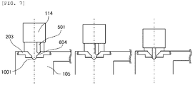
FIG. 7] FIG. 7 is a diagram showing a state in which a protrusion is fitted into a guide groove. - [
FIG. 8] FIG. 8 is an enlarged plan view of a portion where the lubricating member is attached. - [
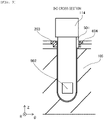
FIG. 9] FIG. 9 is a diagram showing a D-D cross section ofFIG. 8 . - [
FIG. 10] FIG. 10 is a perspective view showing an example of the incubator from which the lubricating member is removed. - [
FIG. 11] FIG. 11 is a plan view showing a schematic configuration of an example of an automatic analyzer for immunological examination. - In the following, preferred embodiments according to the present invention the automatic analyzer will be described with reference to the drawings. Note that in the following description and the accompanying drawings, the redundant description of components having the same functional configurations is omitted by assigning the same reference signs.
- Referring to
Fig. 1 , an example of the overall structure of anautomatic analyzer 100 for biochemical testing will be described. Theautomatic analyzer 100 has asample transport path 103, areagent disk 104, atransfer unit 109, anincubator 105, aspectrophotometer 115, and acontrol unit 111. In the following, the components will be described. Note that the lateral direction inFig. 1 is defined as an X-axis, the vertical direction is defined as a Y-axis, and the vertical direction that is a direction orthogonal to the paper surface is defined as a Z-axis. - The
sample transport path 103 transports asample rack 102 on which a plurality ofsample containers 101 containing a sample is mounted to a position accessible by asample dispensing unit 106. The sample contained in thesample container 101 is dispensed into areaction vessel 114 retained in theincubator 105 by thesample dispensing unit 106. - The
transfer unit 109 grasps and transfers thereaction vessel 114 or a dispensing chip, which is a consumable item disposed in a tray with a gripper. Thereaction vessel 114 to be transferred from the tray to theincubator 105 using thetransfer unit 109 is used for containing a mixed solution of the sample and a reagent is replaced in every analysis. That is, thetransfer unit 109 transfers anunused reaction vessel 114 to theincubator 105. - The
reagent disk 104 keeps a plurality ofreagent containers 112 containing the reagent. In order to mitigate the degradation of the reagent, the inside of thereagent disk 104 is kept at a temperature lower than room temperature. Moreover, thereagent disk 104 is covered with areagent disk cover 113. Note that inFig. 1 , in order to represent a disposition example of thereagent container 112, only a part of thereagent disk cover 113 is shown. The reagent contained in thereagent container 112 is dispensed into thereaction vessel 114 into which the sample is dispensed by thereagent dispensing unit 107. - The
incubator 105 retains a plurality ofreaction vessels 114 containing the mixed solution of the sample and the reagent, and is kept at a predetermined temperature of 37°C, for example, in order to react the mixed solution. The mixed solution is reacted for a predetermined time period in the process of retaining thereaction vessel 114 in theincubator 105 whose temperature is kept at a predetermined temperature, and thus the mixed solution is turned into a reaction solution used for analysis. - The
spectrophotometer 115 measures the absorbance of the reaction solution in order to analyzes specific components included in the reaction solution contained in thereaction vessel 114. Thespectrophotometer 115 is disposed adjacent to theincubator 105, and has a light source, a spectral element, and a photodetector. For the light source, a halogen lamp is used, for the spectral element, a diffraction grating is used, and for the photodetector, a photomultiplier tube, a photodiode, or the like is used. A light beam emitted from the light source is separated into measurement wavelengths by the spectral element, and then applied to the reaction solution contained in thereaction vessel 114, and is detected by the intensity of the light beam transmitted through the reaction solution. An absorbance Aλ relating to a certain wavelength λ is calculated by the following formula using an intensity Iλ0 of a light beam applied to the reaction solution and the intensity of the light beam transmitted through the reaction solution Iλ.
- Moreover, since the absorbance Aλ is proportional to an optical path length L and a concentration C of a specific component included in the reaction solution, the following formula is held.

- The
control unit 111 is a device that controls the operation of the components, accepts inputs of data necessary for analyzes, displays or stores results of analysis, which is, for example, a computer. - Referring to
Fig. 2 , an exemplary configuration of theincubator 105 will be described. Theincubator 105 inFig. 2 has aboard 201 in a ring shape that rotates at a predetermined angle every lapse of a predetermined time period at acentral axis 200 as a rotation axis, aheater 204, and aninsulation 205. In the following, the components will be described. Note that the radial direction of theboard 201 is defined as an R axis, the circumferential direction is defined as aθ axis, and the vertical direction that is a direction in parallel with thecentral axis 200 is defined as a Z-axis. - The
board 201 has a plurality ofholes 202 into which thereaction vessel 114 is inserted along the outer periphery. Note that inFig. 2 , in order to simplify the drawing, only onehole 202 is shown. The inlet ports of theindividual holes 202 are provided with a lubricatingmember 203 that is a member having self lubricity. The self lubricity means that the coefficient of friction of the material itself is extremely small. The lubricatingmember 203 is a material having a coefficient of friction smaller than the coefficient of friction of at least theboard 201, which is PTFE (Poly Tetra FluoroEthylene), polyacetal, ultrahigh molecular polyethylene, monomer-cast nylon, and the like, for example. The lubricatingmember 203 is provided on the inlet port of thehole 202, and thus thereaction vessel 114 can be smoothly inserted into thehole 202. - As shown in
Fig. 3 , even the case in which thereaction vessel 114 is obliquely inserted into thehole 202, smooth insertion is possible. desirably, the gripper of thetransfer unit 109 releases the grasp of the reaction vessel after the reaction vessel is deeply pressed by a predetermined distance from the opening of thehole 202. It should be noted that although the gripper desirably vertically brings down thereaction vessel 114 from right above thehole 202, the grasp may be released after thereaction vessel 114 is intentionally brought into contact with the lubricatingmember 203. - The
heater 204 is a hating resistor in a belt shape that is disposed so as to cover the side surface of the outer periphery of theboard 201, and the supply of electric power is controlled based on the measured value of a thermometer, not shown, provided on theboard 201. Theinsulation 205 is a material having a relatively low coefficient of thermal conductivity, and theinsulation 205 is disposed so as to cover the outer periphery of theheater 204 and the bottom surface of theboard 201. Theboard 201 is kept at a predetermined temperature by the heating of theheater 204 and the insulation of theinsulation 205, the reaction of the mixed solution in thereaction vessel 114 inserted into thehole 202 progresses, and the reaction solution is generated. - On the side surface of the
incubator 105, aphotometric hole 206 is provided, and is used for measuring the absorbance of the reaction solution of thespectrophotometer 115. Thephotometric hole 206 may be provided for everyhole 202 to be inserted into thereaction vessel 114, or may be provided at everyseveral holes 202, for example, at every onehole 202. - Referring to
Fig. 4 , the position at which the lubricatingmember 203 is provided and thephotometric hole 206 will be further described. Since the lubricatingmember 203 is a resin material such as PTFE, and has a relatively low coefficient of thermal conductivity, the lubricatingmember 203 is disposed on the inlet port of thehole 202 so as not to inhibit heat transfer from theboard 201 to thereaction vessel 114. Specifically, the lubricatingmember 203 is preferably provided at a position higher than the liquid level of at least the mixed solution so as not to inhibit heat transfer of the mixed solution contained in thereaction vessel 114. - The
photometric hole 206 is provided such that the inner periphery side communicates with the outer periphery side in the radial direction of theincubator 105 through thehole 202. That is, a light beam emitted from the light source and separated by the spectral element is applied to the reaction solution contained in thereaction vessel 114 through any one of thephotometric holes 206, and the light beam transmitted through the reaction solution is detected by the photodetector through the otherphotometric hole 206. - Referring to
Fig. 5 , and example of thereaction vessel 114 will be described.Fig. 5 shows a side view of thereaction vessel 114 seen from the R direction and a B-B cross sectional view of the side view. Thereaction vessel 114 inFig. 5 has aprotrusion 501 and twotranslucent surfaces 502, and places other than the places at which theprotrusion 501 and thetranslucent surface 502 are provided are in a tubular shape. That is, most of thereaction vessel 114 is in a tubular shape. - The two
translucent surfaces 502 are in parallel with each other, one is a surface into which the separated light beam enters, and the other is a surface through which the transmitted light beam of the reaction solution passes. Preferably, thereaction vessel 114 inserted into thehole 202 is disposed such that thetranslucent surface 502 faces thephotometric hole 206. When thetranslucent surface 502 is disposed so as to face thephotometric hole 206, a distance between the twotranslucent surfaces 502 is the optical path length L. - The
protrusion 501 is a portion protruding from the side surface of thereaction vessel 114, and is provided so as to have a predetermined angle to thetranslucent surface 502 about the central axis of thereaction vessel 114 in parallel with each other the Z-axis. For example, the angle of theprotrusion 501 to thetranslucent surface 502 is 0° such that theprotrusion 501 is in parallel with each other thetranslucent surface 502. - When a certain optical path length L is reserved, the reaction vessel in a tapered shape an reduce the liquid amount of the sample necessary for analysis as the angle formed of the vertical axis and the side surface is reduced, and when the formed angle is at 0°, i.e., when the
reaction vessel 114 is in a tubular shape, the minimum liquid amount is achieved. on the other hand, as the formed angle is reduced, the resistance when thereaction vessel 114 is inserted into thehole 202 of theincubator 105 increases. The increase in resistance at the time of insertion makes the mounting of thereaction vessel 114 on theincubator 105 is uncertain, sometimes leading to the degradation of the processing performance of theautomatic analyzer 100. In the present embodiment, since the lubricatingmember 203 is disposed on the inlet port of thehole 202 of theincubator 105, thereaction vessel 114 is smoothly inserted into thehole 202, and it is possible to maintain the processing performance of theautomatic analyzer 100. - Referring to
Fig. 6 , and example of the lubricatingmember 203 will be described.Fig. 6 shows a plan view of the lubricatingmember 203 seen from the Z-direction, a C-C cross sectional view of the plan view, and a perspective view of the lubricatingmember 203. The lubricatingmember 203 inFig. 6 has an opening through which thereaction vessel 114 passes, acylindrical portion 601, aclaw 602, achamfering portion 603, and aguide groove 604. - The
cylindrical portion 601 is a portion having a tubular shape that is fit into the top end of thehole 202 in order to position the lubricatingmember 203 to thehole 202. That is, the outer diameter of thecylindrical portion 601 nearly matches the inner diameter of the top end of thehole 202. - The
claw 602 is a portion that engages with theincubator 105 in order to prevent the lubricatingmember 203 having self lubricity from falling off from theincubator 105. That is, since there is the case in which the lubricatingmember 203 that is slippery to theincubator 105 falls off even though thereaction vessel 114 slightly touches the lubricatingmember 203, theincubator 105 engages with theclaw 602, and thus the lubricatingmember 203 is prevented from falling off. - The
chamfering portion 603 is an inclined plane provided on the edge of the opening of the lubricatingmember 203 whose side of thehole 202 is low, in order to mitigate the resistance when thereaction vessel 114 is inserted into the lubricatingmember 203. Note that since the coefficient of friction of the lubricatingmember 203 having self lubricity is extremely small, thechamfering portion 603 does not necessarily have to be provided. - Next, the directional portion will be described. The directional portion represents a site having a function that directs the
translucent surface 502 of thereaction vessel 114 to a predetermined direction. - The
guide groove 604 as an example of the directional portion is a groove having a function of facing thetranslucent surface 502 to thephotometric hole 206, into which theprotrusion 501 is fit. That is, in the case in which the angle of theprotrusion 501 to thetranslucent surface 502 is 0°, theguide groove 604 is provided along the circumferential direction of theincubator 105. Theguide groove 604 has a Y-groove shape. Even though theprotrusion 501 is displaced more or less to theguide groove 604, the displacement is corrected along the Y-groove as shown inFig. 7 , and the positioning accuracy of thereaction vessel 114 is reserved. Note that when thetranslucent surface 502 can be directed to the direction of thephotometric hole 206, the directional portion is not limited to theguide groove 604. For example, the site corresponding to theguide groove 604 may be formed in a projecting shape, and the site corresponding to theprotrusion 501 may be formed in a recessed shape. - Referring to
Figs. 8 and9 , thereaction vessel 114 inserted into theincubator 105 mounted on the lubricatingmember 203 will be described. Note that the angle of theprotrusion 501 to thetranslucent surface 502 of thereaction vessel 114 is 0°, and theguide groove 604 of the lubricatingmember 203 is provided along the circumferential direction of theincubator 105. Theprotrusion 501 of thereaction vessel 114 is fit into theguide groove 604 of the lubricatingmember 203, thetranslucent surface 502 of thereaction vessel 114 then faces thephotometric hole 206, and becomes vertical to anoptical path axis 801 of thespectrophotometer 115. - Referring to
Fig. 10 , an example of theincubator 105 from which the lubricatingmember 203 is removed will be described. Theincubator 105 inFig. 10 has aninter-hole groove 1001 along the circumferential direction between theadjacent holes 202. Theinter-hole groove 1001 is provided in parallel with theguide groove 604 of the lubricatingmember 203, and into which theprotrusion 501 of thereaction vessel 114 is fit. Theprotrusion 501 of thereaction vessel 114 is fit into theinter-hole groove 1001 as well as into theguide groove 604 to increase the contact area of theprotrusion 501, leading to resistance to rotation of thereaction vessel 114, and thetranslucent surface 502 is easily vertically aligned with theoptical path axis 801 of thespectrophotometer 115. Moreover, since theinter-hole groove 1001 is provided concentrically with theboard 201 of theincubator 105. - As described above, according to the present embodiment, since the lubricating
member 203 having self lubricity is provided at the inlet port of thehole 202 of theincubator 105, thereaction vessel 114 is smoothly inserted into thehole 202. Such smooth insertion surely mounts thereaction vessel 114 on theincubator 105, and thus it is possible to maintain the processing performance of theautomatic analyzer 100. - In the first embodiment, the
automatic analyzer 100 for biochemical testing has been described. In the present embodiment, anautomatic analyzer 100 for immunologic testing using antigen antibody reactions shown inFig. 11 will be described. Note that differences from the first embodiment are in that configurations involved in analysis and apre-wash unit 108 and ananalysis unit 110 are provided instead of thespectrophotometer 115. - The
pre-wash unit 108 is a device that separates components unnecessary for analysis from a reaction solution. In the present embodiment, a reagent including magnetic fine particles attached with an antibody is used, and an antigen, which is a measured substance in a sample, bonds with the antibody attached to the magnetic fine particles by an immune reaction in anincubator 105. Areaction vessel 114 containing the reaction solution after the immune reaction is transferred to thepre-wash unit 108, and a component that does not bond with the magnetic fine particles, i.e., a component unnecessary for analysis is separated using a magnetic field. Thereaction vessel 114 in which the unnecessary component is separated is returned to theincubator 105, transported to a position at which theanalysis unit 110 is accessible by the rotation of theincubator 105, and then transferred to theanalysis unit 110. - The
analysis unit 110 analyzes the reaction solution from which unnecessary components contained in the transferredreaction vessel 114 is separated. Theanalysis unit 110 has a light source, a spectral element, and a photodetector, and has a function that adjusts temperatures in order to maintain the reproducibility of analysis. Thereaction vessel 114 containing the reaction solution to be analyzed is transferred from theincubator 105 to theanalysis unit 110, and then analyzed by theanalysis unit 110. - Also in the
incubator 105 of the present embodiment, since a lubricatingmember 203 having self lubricity is provided at the inlet port of ahole 202, thereaction vessel 114 is smoothly inserted into thehole 202. Note that theincubator 105 of the present embodiment may include or not include aphotometric hole 206. - In the first embodiment, a case is described in which only one
guide groove 604 as a directional portion is provided. In the present embodiment, a case in which will be described a plurality ofguide grooves 604 is provided. - For example, in the case in which two guide
grooves 604 are provided, twoprotrusions 501 may be provided. In this case, providing two fitting positions further improve positioning accuracy. The twoguide grooves 604 and the twoprotrusions 501 may be provided at opposite positions, or may be provided with a given angle difference. Also in regard to shapes, the first protrusion and the second protrusion may have different shapes. To the two guide grooves, oneprotrusion 501 may be provided, and the numbers of theguide grooves 604 and theprotrusions 501 do not necessarily have to be the same. Furthermore, the number of theguide grooves 604 is not limited in the range in which theguide grooves 604 can be provided at thehole 202, as long as the numbers of theguide grooves 604 is equal to or more than the number of theprotrusions 501. - As described above, a plurality of embodiments according to the present invention is described. The present invention is not limited to the foregoing embodiments, and may be modified in the scope not deviating from the gist of the invention. For example, the shape of the
incubator 105 may be in a ring shape as shown inFig. 2 , or may be in a shape in which thereaction vessels 114 are linearly arranged. Moreover, a plurality of components disclosed in the foregoing embodiments may be appropriately combined. Furthermore, some components may be removed from all the components shown in the foregoing embodiments. -
- 101:
- sample container
- 102:
- sample rack
- 103:
- sample transport path
- 104:
- reagent disk
- 105:
- incubator
- 106:
- sample dispensing unit
- 107:
- reagent dispensing unit
- 108:
- pre-wash unit
- 109:
- transfer unit
- 110:
- analysis unit
- 111:
- control unit
- 112:
- reagent container
- 113:
- reagent disk cover
- 114:
- reaction container
- 115:
- spectrophotometer
- 200:
- central axis
- 201:
- board
- 202:
- hole
- 203:
- lubricating member
- 204:
- heater
- 205:
- insulation
- 206:
- photometric hole
- 501:
- protrusion
- 502:
- translucent surface
- 601:
- cylindrical portion
- 602:
- claw
- 603:
- chamfering portion
- 604:
- guide groove
- 801:
- optical path axis
- 1001:
- inter-hole groove
Claims (9)
- An automatic analyzer, comprising:an incubator having a hole into which a reaction container containing a mixture of a sample and a reagent is to be inserted; anda transfer unit configured to transfer an unused reaction container to the incubator and insert the reaction container into the hole, whereina lubricating member having a self-lubricating property is provided at an inlet port of the hole.
- The automatic analyzer according to claim 1, whereinthe reaction container has a translucent surface which is a flat surface through which light for analysis is to be transmitted,and the lubricating member has a directional portion that directs the translucent surface in a predetermined direction.
- The automatic analyzer according to claim 2, whereinthe reaction container further has a protrusion that protrudes from a side surface, andthe directional portion has a guide groove which is a groove that fits with the protrusion.
- The automatic analyzer according to claim 3, wherein
the incubator has a groove parallel to the guide groove. - The automatic analyzer according to claim 1, wherein
the lubricating member is provided at a position higher than a liquid level of the mixture contained in the reaction container. - The automatic analyzer according to claim 1, wherein
a material of the lubricating member is any one of PTFE, polyacetal, ultra-high molecular weight polyethylene, or monomer cast nylon. - The automatic analyzer according to claim 1, wherein
the lubricating member has a claw that meshes with the incubator. - The automatic analyzer according to claim 1, wherein
the lubricating member has a chamfering portion which is an inclined surface that is lower toward the hole. - An insertion method of a reaction container in an automatic analyzer, the automatic analyzer including:an incubator having a hole into which a reaction container containing a mixture of a sample and a reagent is inserted; anda transfer unit that transfers an unused reaction container to the incubator and inserts the reaction container into the hole, the insertion method comprising:a step of the transfer unit inserting the reaction container into the hole while gripping the reaction container; anda step of bringing the reaction container into contact with a lubricating member having a self-lubricating property that is provided at an inlet port of the hole.
Applications Claiming Priority (2)
| Application Number | Priority Date | Filing Date | Title |
|---|---|---|---|
| JP2020083219 | 2020-05-11 | ||
| PCT/JP2021/004449 WO2021229874A1 (en) | 2020-05-11 | 2021-02-05 | Automatic analysis device and method for inserting reaction container |
Publications (3)
| Publication Number | Publication Date |
|---|---|
| EP4152006A1 true EP4152006A1 (en) | 2023-03-22 |
| EP4152006A4 EP4152006A4 (en) | 2024-05-22 |
| EP4152006B1 EP4152006B1 (en) | 2025-07-09 |
Family
ID=78525779
Family Applications (1)
| Application Number | Title | Priority Date | Filing Date |
|---|---|---|---|
| EP21802189.7A Active EP4152006B1 (en) | 2020-05-11 | 2021-02-05 | Automatic analysis device |
Country Status (5)
| Country | Link |
|---|---|
| US (1) | US12566189B2 (en) |
| EP (1) | EP4152006B1 (en) |
| JP (1) | JP7379692B2 (en) |
| CN (1) | CN115461625B (en) |
| WO (1) | WO2021229874A1 (en) |
Family Cites Families (28)
| Publication number | Priority date | Publication date | Assignee | Title |
|---|---|---|---|---|
| US4310488A (en) * | 1980-05-19 | 1982-01-12 | Hoffmann-La Roche Inc. | Sample or reagent container for analyzers |
| JPH05142234A (en) | 1991-11-15 | 1993-06-08 | Olympus Optical Co Ltd | Reaction container holder for automatic analyzer |
| EP0601173B1 (en) | 1992-06-29 | 1997-03-05 | Dade International Inc. | Sample tube carrier |
| US5976896A (en) * | 1994-06-06 | 1999-11-02 | Idexx Laboratories, Inc. | Immunoassays in capillary tubes |
| US5599501A (en) | 1994-11-10 | 1997-02-04 | Ciba Corning Diagnostics Corp. | Incubation chamber |
| AR005685A1 (en) * | 1996-02-02 | 1999-07-14 | Ortho Diagnostic Systems Inc | AGGREGATION AND SEPARATION REACTION CONTAINER; CASSETTE SEALED BY A METALLIC SHEET THAT UNDERSTANDS IT AND CASES TO PREVENT CROSS CONTAMINATION IN A COLUMN OF SUCH CASSETTE |
| US5632399A (en) * | 1996-06-28 | 1997-05-27 | Dpc Cirrus Inc. | Self-sealing reagent container and reagent container system |
| US8337753B2 (en) * | 1998-05-01 | 2012-12-25 | Gen-Probe Incorporated | Temperature-controlled incubator having a receptacle mixing mechanism |
| JP2003107096A (en) * | 2001-09-28 | 2003-04-09 | Hitachi Ltd | Automatic analyzer |
| JP2005507074A (en) * | 2001-10-26 | 2005-03-10 | セクエノム, インコーポレイテッド | Method and apparatus for a high throughput sample handling process line |
| GB0322444D0 (en) * | 2003-09-25 | 2003-10-29 | Rts Thurnall Plc | Actuator assembly |
| JP4564822B2 (en) * | 2004-10-27 | 2010-10-20 | 株式会社日立ハイテクノロジーズ | Reaction vessel and automatic analyzer using the same |
| US7776263B2 (en) * | 2004-10-29 | 2010-08-17 | Abbott Laboratories Inc. | Apparatus for providing homogeneous dispersions |
| JP2008521432A (en) * | 2004-11-30 | 2008-06-26 | グローバル テクノロジーズ (エヌゼット) リミテッド | Sample analysis method and apparatus therefor |
| JP2006292696A (en) * | 2005-04-15 | 2006-10-26 | Hitachi High-Technologies Corp | Sample rack and sample rack adapter |
| JP2008241500A (en) * | 2007-03-28 | 2008-10-09 | Fujifilm Corp | Microchip positioning member |
| US8486346B2 (en) * | 2008-05-19 | 2013-07-16 | Abbott Laboratories | Gas scrubber for automated clinical analyzer |
| GB201005885D0 (en) * | 2010-04-08 | 2010-05-26 | Avacta Ltd | Apparatus and method |
| US9046507B2 (en) * | 2010-07-29 | 2015-06-02 | Gen-Probe Incorporated | Method, system and apparatus for incorporating capacitive proximity sensing in an automated fluid transfer procedure |
| CN202304645U (en) * | 2011-11-07 | 2012-07-04 | 攀钢集团工程技术有限公司 | Pipe cap used for medicine conveying pipe of charging trolley |
| CN104661754B (en) * | 2013-01-09 | 2018-03-27 | 泰肯贸易股份公司 | Replaceable box body for microfluid system |
| JP6348816B2 (en) * | 2014-09-30 | 2018-06-27 | 株式会社日立ハイテクノロジーズ | Automatic analyzer |
| US10379130B2 (en) * | 2015-06-26 | 2019-08-13 | Abbott Laboratories | Reaction vessel exchanger device for a diagnostic analyzer |
| US11300488B2 (en) | 2017-02-07 | 2022-04-12 | Hitachi High-Tech Corporation | Automatic analysis device |
| JP6948158B2 (en) * | 2017-05-29 | 2021-10-13 | シスメックス株式会社 | Sample processing equipment and sample processing method |
| PL3710845T3 (en) * | 2017-11-17 | 2021-12-27 | Numares Ag | Nmr arrangement and method for transporting a sample tube in an nmr arrangement |
| US20200393479A1 (en) * | 2018-02-23 | 2020-12-17 | Siemens Healthcare Diagnostics Inc. | Clinical analyzers and methods for transporting cuvettes |
| US11965820B2 (en) | 2018-09-27 | 2024-04-23 | Hitachi High-Tech Corporation | Reaction vessel for automatic analyzer |
-
2021
- 2021-02-05 EP EP21802189.7A patent/EP4152006B1/en active Active
- 2021-02-05 WO PCT/JP2021/004449 patent/WO2021229874A1/en not_active Ceased
- 2021-02-05 CN CN202180028233.0A patent/CN115461625B/en active Active
- 2021-02-05 JP JP2022522519A patent/JP7379692B2/en active Active
- 2021-02-05 US US17/923,685 patent/US12566189B2/en active Active
Also Published As
| Publication number | Publication date |
|---|---|
| US12566189B2 (en) | 2026-03-03 |
| EP4152006A4 (en) | 2024-05-22 |
| JP7379692B2 (en) | 2023-11-14 |
| EP4152006B1 (en) | 2025-07-09 |
| CN115461625A (en) | 2022-12-09 |
| JPWO2021229874A1 (en) | 2021-11-18 |
| CN115461625B (en) | 2025-10-28 |
| WO2021229874A1 (en) | 2021-11-18 |
| US20230184797A1 (en) | 2023-06-15 |
Similar Documents
| Publication | Publication Date | Title |
|---|---|---|
| JP6813953B2 (en) | Blood coagulation analyzer and blood coagulation analysis method | |
| US5986754A (en) | Medical diagnostic apparatus using a Fresnel reflector | |
| US4406547A (en) | Apparatus for effecting automatic analysis | |
| US9612192B2 (en) | Cuvette for photometric measurement of small liquid volumes | |
| EP2605020B1 (en) | Method of specimen analysis and specimen analyzer | |
| US8064061B2 (en) | Sample analyzer and sample analyzing method | |
| JP2006526778A (en) | Read head for optical inspection equipment | |
| EP2466292A1 (en) | System for performing scattering and absorbance assays | |
| JP2007322208A (en) | Biochemical analyzer | |
| JP7660181B2 (en) | Blood coagulation analyzer and blood coagulation analysis method | |
| EP4152006B1 (en) | Automatic analysis device | |
| EP2607883A1 (en) | System for photometric measurement of liquids | |
| Schultz et al. | Two-dimensional centrifugation for desk-top clinical chemistry. | |
| WO2011136265A1 (en) | Optical analyzer | |
| US6630108B1 (en) | Optical measuring head, in particular for automatic chemical or biological reaction analyzer | |
| EP0110262A2 (en) | Optical readhead | |
| EP0864867A2 (en) | Improved analyzer throughput featuring through-the-tip analysis | |
| JP7546141B2 (en) | Light source and automatic analyzer | |
| JP7094390B2 (en) | A spectrophotometer, a spectrophotometer, and a method for manufacturing a spectrophotometer. | |
| JP7649856B2 (en) | Automated analyzer and reaction vessel | |
| JP4838086B2 (en) | Chemiluminescence measuring device | |
| CA1199258A (en) | Automated analysis instrument system | |
| JPS6111631A (en) | Stop position detector of cartridge containing slide for chemical analysis | |
| JP2001074553A (en) | Biochemical analyzer | |
| CN117396748A (en) | Photometric and analytical devices |
Legal Events
| Date | Code | Title | Description |
|---|---|---|---|
| STAA | Information on the status of an ep patent application or granted ep patent |
Free format text: STATUS: THE INTERNATIONAL PUBLICATION HAS BEEN MADE |
|
| PUAI | Public reference made under article 153(3) epc to a published international application that has entered the european phase |
Free format text: ORIGINAL CODE: 0009012 |
|
| STAA | Information on the status of an ep patent application or granted ep patent |
Free format text: STATUS: REQUEST FOR EXAMINATION WAS MADE |
|
| 17P | Request for examination filed |
Effective date: 20221020 |
|
| AK | Designated contracting states |
Kind code of ref document: A1 Designated state(s): AL AT BE BG CH CY CZ DE DK EE ES FI FR GB GR HR HU IE IS IT LI LT LU LV MC MK MT NL NO PL PT RO RS SE SI SK SM TR |
|
| DAV | Request for validation of the european patent (deleted) | ||
| DAX | Request for extension of the european patent (deleted) | ||
| A4 | Supplementary search report drawn up and despatched |
Effective date: 20240419 |
|
| RIC1 | Information provided on ipc code assigned before grant |
Ipc: G01N 35/04 20060101ALI20240415BHEP Ipc: G01N 35/02 20060101AFI20240415BHEP |
|
| GRAP | Despatch of communication of intention to grant a patent |
Free format text: ORIGINAL CODE: EPIDOSNIGR1 |
|
| STAA | Information on the status of an ep patent application or granted ep patent |
Free format text: STATUS: GRANT OF PATENT IS INTENDED |
|
| INTG | Intention to grant announced |
Effective date: 20250320 |
|
| GRAS | Grant fee paid |
Free format text: ORIGINAL CODE: EPIDOSNIGR3 |
|
| GRAA | (expected) grant |
Free format text: ORIGINAL CODE: 0009210 |
|
| STAA | Information on the status of an ep patent application or granted ep patent |
Free format text: STATUS: THE PATENT HAS BEEN GRANTED |
|
| AK | Designated contracting states |
Kind code of ref document: B1 Designated state(s): AL AT BE BG CH CY CZ DE DK EE ES FI FR GB GR HR HU IE IS IT LI LT LU LV MC MK MT NL NO PL PT RO RS SE SI SK SM TR |
|
| REG | Reference to a national code |
Ref country code: GB Ref legal event code: FG4D |
|
| REG | Reference to a national code |
Ref country code: CH Ref legal event code: EP |
|
| REG | Reference to a national code |
Ref country code: IE Ref legal event code: FG4D |
|
| REG | Reference to a national code |
Ref country code: DE Ref legal event code: R096 Ref document number: 602021033889 Country of ref document: DE |
|
| REG | Reference to a national code |
Ref country code: NL Ref legal event code: MP Effective date: 20250709 |
|
| PG25 | Lapsed in a contracting state [announced via postgrant information from national office to epo] |
Ref country code: PT Free format text: LAPSE BECAUSE OF FAILURE TO SUBMIT A TRANSLATION OF THE DESCRIPTION OR TO PAY THE FEE WITHIN THE PRESCRIBED TIME-LIMIT Effective date: 20251110 |
|
| PG25 | Lapsed in a contracting state [announced via postgrant information from national office to epo] |
Ref country code: NL Free format text: LAPSE BECAUSE OF FAILURE TO SUBMIT A TRANSLATION OF THE DESCRIPTION OR TO PAY THE FEE WITHIN THE PRESCRIBED TIME-LIMIT Effective date: 20250709 |
|
| REG | Reference to a national code |
Ref country code: AT Ref legal event code: MK05 Ref document number: 1812260 Country of ref document: AT Kind code of ref document: T Effective date: 20250709 |
|
| PG25 | Lapsed in a contracting state [announced via postgrant information from national office to epo] |
Ref country code: IS Free format text: LAPSE BECAUSE OF FAILURE TO SUBMIT A TRANSLATION OF THE DESCRIPTION OR TO PAY THE FEE WITHIN THE PRESCRIBED TIME-LIMIT Effective date: 20251109 |
|
| PG25 | Lapsed in a contracting state [announced via postgrant information from national office to epo] |
Ref country code: NO Free format text: LAPSE BECAUSE OF FAILURE TO SUBMIT A TRANSLATION OF THE DESCRIPTION OR TO PAY THE FEE WITHIN THE PRESCRIBED TIME-LIMIT Effective date: 20251009 |
|
| REG | Reference to a national code |
Ref country code: LT Ref legal event code: MG9D |
|
| PG25 | Lapsed in a contracting state [announced via postgrant information from national office to epo] |
Ref country code: AT Free format text: LAPSE BECAUSE OF FAILURE TO SUBMIT A TRANSLATION OF THE DESCRIPTION OR TO PAY THE FEE WITHIN THE PRESCRIBED TIME-LIMIT Effective date: 20250709 |
|
| PG25 | Lapsed in a contracting state [announced via postgrant information from national office to epo] |
Ref country code: FI Free format text: LAPSE BECAUSE OF FAILURE TO SUBMIT A TRANSLATION OF THE DESCRIPTION OR TO PAY THE FEE WITHIN THE PRESCRIBED TIME-LIMIT Effective date: 20250709 |
|
| PG25 | Lapsed in a contracting state [announced via postgrant information from national office to epo] |
Ref country code: HR Free format text: LAPSE BECAUSE OF FAILURE TO SUBMIT A TRANSLATION OF THE DESCRIPTION OR TO PAY THE FEE WITHIN THE PRESCRIBED TIME-LIMIT Effective date: 20250709 |
|
| PG25 | Lapsed in a contracting state [announced via postgrant information from national office to epo] |
Ref country code: GR Free format text: LAPSE BECAUSE OF FAILURE TO SUBMIT A TRANSLATION OF THE DESCRIPTION OR TO PAY THE FEE WITHIN THE PRESCRIBED TIME-LIMIT Effective date: 20251010 |
|
| PG25 | Lapsed in a contracting state [announced via postgrant information from national office to epo] |
Ref country code: SE Free format text: LAPSE BECAUSE OF FAILURE TO SUBMIT A TRANSLATION OF THE DESCRIPTION OR TO PAY THE FEE WITHIN THE PRESCRIBED TIME-LIMIT Effective date: 20250709 |
|
| PG25 | Lapsed in a contracting state [announced via postgrant information from national office to epo] |
Ref country code: LV Free format text: LAPSE BECAUSE OF FAILURE TO SUBMIT A TRANSLATION OF THE DESCRIPTION OR TO PAY THE FEE WITHIN THE PRESCRIBED TIME-LIMIT Effective date: 20250709 |
|
| PG25 | Lapsed in a contracting state [announced via postgrant information from national office to epo] |
Ref country code: BG Free format text: LAPSE BECAUSE OF FAILURE TO SUBMIT A TRANSLATION OF THE DESCRIPTION OR TO PAY THE FEE WITHIN THE PRESCRIBED TIME-LIMIT Effective date: 20250709 Ref country code: PL Free format text: LAPSE BECAUSE OF FAILURE TO SUBMIT A TRANSLATION OF THE DESCRIPTION OR TO PAY THE FEE WITHIN THE PRESCRIBED TIME-LIMIT Effective date: 20250709 |
|
| PG25 | Lapsed in a contracting state [announced via postgrant information from national office to epo] |
Ref country code: RS Free format text: LAPSE BECAUSE OF FAILURE TO SUBMIT A TRANSLATION OF THE DESCRIPTION OR TO PAY THE FEE WITHIN THE PRESCRIBED TIME-LIMIT Effective date: 20251009 |
|
| PG25 | Lapsed in a contracting state [announced via postgrant information from national office to epo] |
Ref country code: ES Free format text: LAPSE BECAUSE OF FAILURE TO SUBMIT A TRANSLATION OF THE DESCRIPTION OR TO PAY THE FEE WITHIN THE PRESCRIBED TIME-LIMIT Effective date: 20250709 |
|
| PG25 | Lapsed in a contracting state [announced via postgrant information from national office to epo] |
Ref country code: SM Free format text: LAPSE BECAUSE OF FAILURE TO SUBMIT A TRANSLATION OF THE DESCRIPTION OR TO PAY THE FEE WITHIN THE PRESCRIBED TIME-LIMIT Effective date: 20250709 |
|
| REG | Reference to a national code |
Ref country code: DE Ref legal event code: R097 Ref document number: 602021033889 Country of ref document: DE |
|
| PG25 | Lapsed in a contracting state [announced via postgrant information from national office to epo] |
Ref country code: DK Free format text: LAPSE BECAUSE OF FAILURE TO SUBMIT A TRANSLATION OF THE DESCRIPTION OR TO PAY THE FEE WITHIN THE PRESCRIBED TIME-LIMIT Effective date: 20250709 |
|
| PGFP | Annual fee paid to national office [announced via postgrant information from national office to epo] |
Ref country code: DE Payment date: 20260223 Year of fee payment: 6 |
|
| PG25 | Lapsed in a contracting state [announced via postgrant information from national office to epo] |
Ref country code: IT Free format text: LAPSE BECAUSE OF FAILURE TO SUBMIT A TRANSLATION OF THE DESCRIPTION OR TO PAY THE FEE WITHIN THE PRESCRIBED TIME-LIMIT Effective date: 20250709 |
|
| PGFP | Annual fee paid to national office [announced via postgrant information from national office to epo] |
Ref country code: FR Payment date: 20260227 Year of fee payment: 6 |
|
| PG25 | Lapsed in a contracting state [announced via postgrant information from national office to epo] |
Ref country code: CZ Free format text: LAPSE BECAUSE OF FAILURE TO SUBMIT A TRANSLATION OF THE DESCRIPTION OR TO PAY THE FEE WITHIN THE PRESCRIBED TIME-LIMIT Effective date: 20250709 |
|
| PG25 | Lapsed in a contracting state [announced via postgrant information from national office to epo] |
Ref country code: EE Free format text: LAPSE BECAUSE OF FAILURE TO SUBMIT A TRANSLATION OF THE DESCRIPTION OR TO PAY THE FEE WITHIN THE PRESCRIBED TIME-LIMIT Effective date: 20250709 Ref country code: SK Free format text: LAPSE BECAUSE OF FAILURE TO SUBMIT A TRANSLATION OF THE DESCRIPTION OR TO PAY THE FEE WITHIN THE PRESCRIBED TIME-LIMIT Effective date: 20250709 |
|
| PLBE | No opposition filed within time limit |
Free format text: ORIGINAL CODE: 0009261 |
|
| STAA | Information on the status of an ep patent application or granted ep patent |
Free format text: STATUS: NO OPPOSITION FILED WITHIN TIME LIMIT |
|
| REG | Reference to a national code |
Ref country code: CH Ref legal event code: L10 Free format text: ST27 STATUS EVENT CODE: U-0-0-L10-L00 (AS PROVIDED BY THE NATIONAL OFFICE) Effective date: 20260521 |
|
| 26N | No opposition filed |
Effective date: 20260410 |
|
| PG25 | Lapsed in a contracting state [announced via postgrant information from national office to epo] |
Ref country code: LT Free format text: LAPSE BECAUSE OF FAILURE TO SUBMIT A TRANSLATION OF THE DESCRIPTION OR TO PAY THE FEE WITHIN THE PRESCRIBED TIME-LIMIT Effective date: 20250709 |