EP4151945B1 - Kühlkörper und herstellungsverfahren für ein kühlkörperrippenelement - Google Patents
Kühlkörper und herstellungsverfahren für ein kühlkörperrippenelement Download PDFInfo
- Publication number
- EP4151945B1 EP4151945B1 EP21197755.8A EP21197755A EP4151945B1 EP 4151945 B1 EP4151945 B1 EP 4151945B1 EP 21197755 A EP21197755 A EP 21197755A EP 4151945 B1 EP4151945 B1 EP 4151945B1
- Authority
- EP
- European Patent Office
- Prior art keywords
- fin
- base plate
- heat sink
- sink device
- plate element
- Prior art date
- Legal status (The legal status is an assumption and is not a legal conclusion. Google has not performed a legal analysis and makes no representation as to the accuracy of the status listed.)
- Active
Links
Images


Classifications
-
- F—MECHANICAL ENGINEERING; LIGHTING; HEATING; WEAPONS; BLASTING
- F28—HEAT EXCHANGE IN GENERAL
- F28F—DETAILS OF HEAT-EXCHANGE AND HEAT-TRANSFER APPARATUS, OF GENERAL APPLICATION
- F28F3/00—Plate-like or laminated elements; Assemblies of plate-like or laminated elements
- F28F3/02—Elements or assemblies thereof with means for increasing heat-transfer area, e.g. with fins, with recesses, with corrugations
- F28F3/04—Elements or assemblies thereof with means for increasing heat-transfer area, e.g. with fins, with recesses, with corrugations the means being integral with the element
- F28F3/048—Elements or assemblies thereof with means for increasing heat-transfer area, e.g. with fins, with recesses, with corrugations the means being integral with the element in the form of ribs integral with the element or local variations in thickness of the element, e.g. grooves, microchannels
-
- B—PERFORMING OPERATIONS; TRANSPORTING
- B21—MECHANICAL METAL-WORKING WITHOUT ESSENTIALLY REMOVING MATERIAL; PUNCHING METAL
- B21D—WORKING OR PROCESSING OF SHEET METAL OR METAL TUBES, RODS OR PROFILES WITHOUT ESSENTIALLY REMOVING MATERIAL; PUNCHING METAL
- B21D22/00—Shaping without cutting, by stamping, spinning, or deep-drawing
- B21D22/02—Stamping using rigid devices or tools
-
- B—PERFORMING OPERATIONS; TRANSPORTING
- B21—MECHANICAL METAL-WORKING WITHOUT ESSENTIALLY REMOVING MATERIAL; PUNCHING METAL
- B21D—WORKING OR PROCESSING OF SHEET METAL OR METAL TUBES, RODS OR PROFILES WITHOUT ESSENTIALLY REMOVING MATERIAL; PUNCHING METAL
- B21D53/00—Making other particular articles
- B21D53/02—Making other particular articles heat exchangers or parts thereof, e.g. radiators, condensers fins, headers
- B21D53/022—Making the fins
-
- B—PERFORMING OPERATIONS; TRANSPORTING
- B21—MECHANICAL METAL-WORKING WITHOUT ESSENTIALLY REMOVING MATERIAL; PUNCHING METAL
- B21D—WORKING OR PROCESSING OF SHEET METAL OR METAL TUBES, RODS OR PROFILES WITHOUT ESSENTIALLY REMOVING MATERIAL; PUNCHING METAL
- B21D53/00—Making other particular articles
- B21D53/02—Making other particular articles heat exchangers or parts thereof, e.g. radiators, condensers fins, headers
- B21D53/04—Making other particular articles heat exchangers or parts thereof, e.g. radiators, condensers fins, headers of sheet metal
-
- F—MECHANICAL ENGINEERING; LIGHTING; HEATING; WEAPONS; BLASTING
- F28—HEAT EXCHANGE IN GENERAL
- F28F—DETAILS OF HEAT-EXCHANGE AND HEAT-TRANSFER APPARATUS, OF GENERAL APPLICATION
- F28F13/00—Arrangements for modifying heat-transfer, e.g. increasing, decreasing
- F28F13/02—Arrangements for modifying heat-transfer, e.g. increasing, decreasing by influencing fluid boundary
-
- F—MECHANICAL ENGINEERING; LIGHTING; HEATING; WEAPONS; BLASTING
- F28—HEAT EXCHANGE IN GENERAL
- F28F—DETAILS OF HEAT-EXCHANGE AND HEAT-TRANSFER APPARATUS, OF GENERAL APPLICATION
- F28F13/00—Arrangements for modifying heat-transfer, e.g. increasing, decreasing
- F28F13/06—Arrangements for modifying heat-transfer, e.g. increasing, decreasing by affecting the pattern of flow of the heat-exchange media
- F28F13/08—Arrangements for modifying heat-transfer, e.g. increasing, decreasing by affecting the pattern of flow of the heat-exchange media by varying the cross-section of the flow channels
-
- F—MECHANICAL ENGINEERING; LIGHTING; HEATING; WEAPONS; BLASTING
- F28—HEAT EXCHANGE IN GENERAL
- F28F—DETAILS OF HEAT-EXCHANGE AND HEAT-TRANSFER APPARATUS, OF GENERAL APPLICATION
- F28F3/00—Plate-like or laminated elements; Assemblies of plate-like or laminated elements
- F28F3/02—Elements or assemblies thereof with means for increasing heat-transfer area, e.g. with fins, with recesses, with corrugations
- F28F3/04—Elements or assemblies thereof with means for increasing heat-transfer area, e.g. with fins, with recesses, with corrugations the means being integral with the element
- F28F3/042—Elements or assemblies thereof with means for increasing heat-transfer area, e.g. with fins, with recesses, with corrugations the means being integral with the element in the form of local deformations of the element
- F28F3/044—Elements or assemblies thereof with means for increasing heat-transfer area, e.g. with fins, with recesses, with corrugations the means being integral with the element in the form of local deformations of the element the deformations being pontual, e.g. dimples
-
- H10W40/226—
-
- H10W40/43—
-
- F—MECHANICAL ENGINEERING; LIGHTING; HEATING; WEAPONS; BLASTING
- F28—HEAT EXCHANGE IN GENERAL
- F28D—HEAT-EXCHANGE APPARATUS, NOT PROVIDED FOR IN ANOTHER SUBCLASS, IN WHICH THE HEAT-EXCHANGE MEDIA DO NOT COME INTO DIRECT CONTACT
- F28D21/00—Heat-exchange apparatus not covered by any of the groups F28D1/00 - F28D20/00
- F28D2021/0019—Other heat exchangers for particular applications; Heat exchange systems not otherwise provided for
- F28D2021/0028—Other heat exchangers for particular applications; Heat exchange systems not otherwise provided for for cooling heat generating elements, e.g. for cooling electronic components or electric devices
- F28D2021/0029—Heat sinks
-
- F—MECHANICAL ENGINEERING; LIGHTING; HEATING; WEAPONS; BLASTING
- F28—HEAT EXCHANGE IN GENERAL
- F28F—DETAILS OF HEAT-EXCHANGE AND HEAT-TRANSFER APPARATUS, OF GENERAL APPLICATION
- F28F2215/00—Fins
- F28F2215/10—Secondary fins, e.g. projections or recesses on main fins
-
- F—MECHANICAL ENGINEERING; LIGHTING; HEATING; WEAPONS; BLASTING
- F28—HEAT EXCHANGE IN GENERAL
- F28F—DETAILS OF HEAT-EXCHANGE AND HEAT-TRANSFER APPARATUS, OF GENERAL APPLICATION
- F28F2250/00—Arrangements for modifying the flow of the heat exchange media, e.g. flow guiding means; Particular flow patterns
- F28F2250/02—Streamline-shaped elements
Definitions
- the disclosure relates to a heat sink device and a method for manufacturing a heat sink fin element.
- Such technical devices can be electronic, but also mechanical devices.
- Such undesired heating can cause trouble as the devices need to be protected from overheating. This can affect up-times of technical devices, their maintenance, but also their operation conditions and environment.
- Thermal management of a technical device is often a major consideration during product development or layout. Subject of discussion is often what amount of heat can be removed and how fast such heat can be removed from the technical device.
- heat sink device If the heat is removed by a fluid from the heat sink device, more powerful pumping units, pumping the fluid, are considered, e.g. in case of air as fluid more powerful fans. Also the surface areas of heat sink devices for heat exchange with the fluid can be increased. These factors affect the technical device in terms of form factor, cost, reliability and user experience.
- An exemplary cooling system is e.g. disclosed in US 5823249 .
- the presented teaching uses fin elements with airfoil shape to avoid eddy currents trailing the airfoils which require input energy to the airflow and which do nothing to transfer heat from the airfoil to the flowing air.
- US 2014/015 101.0 A1 discloses also a heat sink with a base having a structure side and an opposite environmental side.
- the structure side of the base is configured to thermally communicate with a structure for absorbing heat from the structure.
- a cooling fin extends a height outwardly from the environmental side of the base.
- the cooling fin extends a chord length along the base from a leading edge to a trailing edge of the cooling fin.
- the cooling fin includes the cross-sectional shape of an airfoil along at least a portion of the height of the cooling fin to increase the velocity of a flow of air along the cord length of the cooling fin.
- WO 2020/232178 A1 concerns also a thermal management system which utilizes a fin in thermal contact with a heat pipe, wherein said fin comprises a fluid flow path in fluid communication with a first opening and a second opening of said fin, wherein said fluid flow path is configured to direct a second working fluid from said first opening to said second opening, wherein said first opening is oriented along a first direction of flow of said second working fluid towards said fin, and wherein said second opening is oriented along a second direction that is different than said first direction.
- Such fin can be configured as an airfoil.
- Document DE 10 2015 205 902 A1 discloses a method for manufacturing a heat sink fin element with a stamped part that has an airfoil cross-section.
- Airfoil shapes of cooling fins have proven to be advantageous in connection with laminarly flowing fluids receiving the heat from the cooling fins. Due to the reduced flow resistance if the airfoil shape of the fin the amount of heat transfer between the fin and the working fluid is increased.
- a heat sink device comprising a base plate element, a first fin element arranged at the base plate element, whereas at least one out of the group of the base plate element, and the first fin element is configured to comprise an airfoil-shaped cross-section, whereas the base plate element comprises at least one bulge configured to generate vortices in a fluid flow passing the base plate element, characterized in that the base plate element comprises an airfoil-shaped cross-section extending from a leading edge to a trailing edge of the base plate element in a main flow direction.
- the heat exchange can be significantly increased between the heat sink device and a fluid passing the heat sink device.
- Such bulge is configured to generate vortices which cause a delayed flow separation and/or reduce the pressure drag.
- the bulges also have the effect to cause a pressure gradient directed towards the surface of the base plate element. This leads to an increased density of a compressible fluid close to the surface of the base plate element.
- a fluid passing the base plate element means that the fluid is enabled to receive heat from the base plate element whereas while it passes the base plate element, especially the fluid is in direct contact with the base plate element.
- the fluid flow is laminar flowing towards the heat sink device and stays laminar besides the vortices generated by a bulge, respectively the plurality of bulges.
- a term “bulge” shall be considered a physical structure configured to generate vortices in the fluid stream close to the base plate element surface.
- the bulge can be realized as protuberance, e.g. a protrusion or a outward dimple, but also as cavity, e.g. a recess or inward dimple, on the surface of the base plate element.
- a second fin element may be arranged at the first fin element.
- the second fin element may also comprise an airfoil-shaped cross-section, while with a second fin element the first fin element not necessarily needs to comprise an airfoil-shaped cross-section.
- Such bulges can in addition be comprised by the first fin element and/or second fin element, respectively by the surface of the first and/or second fin element, especially, if the first and/or second fin element has an airfoil-shaped cross-section.
- the size and/or form of the bulge is adjusted to the used fluid and its Reynolds number. Further it is advantageous, if the bulge is configured to have a closed surface, i.e. the surface of the bulge is non-transparent for the fluid flow perpendicular to a main flow direction of the fluid.
- airfoil shaped cross-section generally refers to a cross-section of a base plate element or a first or second fin element that generates a pressure differential and/or an aerodynamic force (e.g., a lift force) as a laminar fluid flows over it.
- Airfoil profiles can be implemented in common manufacturing technologies, e.g. sheet metal, milling or heatsink blazing. Examples of objects having an airfoil-shaped cross-section include a wing, a compressor rotor, a stator, a turbine blade, and/or a vane.
- the heat sink device can comprise a base plate element and a first fin element arranged on the base plate element.
- the heat sink device can also comprise a base plate element, a first fin element and a second fin element arranged at the first fin element, whereas the first fin element is attached at the base plate element.
- the heat sink device can also comprise a first fin element without second fin element and in addition a first fin element on which a second fin element is arranged. At least one of the base plate element, a first fin element and a second fin element, if any, shall be configured to have an airfoil-shaped cross-section.
- At least one of the group of the base plate element, the first fin element and the second fin element shall be configured to have an airfoil-shaped cross-section.
- the first fin element and the second fin element can be configured to have an airfoil-shaped cross-section.
- the base plate element can be configured to have an airfoil-shaped cross-section and the second fin element, if any, can be configured to have an airfoil-shaped cross-section.
- any combination of airfoil-based cross-sections from the group of the base plate element, the first fin element and the second fin element is considered comprised by the invention.
- the base plate element and/or the fin element can be made from a material with high thermal conductivity, especially metal.
- the base plate element can be provided as a one-piece base plate element or can be assembled by several elements, which form together the base plate element.
- the first fin element can be provided as a one-piece fin element or can be assembled by several elements, which form together the first fin element.
- the second fin element can be provided as a one-piece fin element or can be assembled by several elements, which form together the second fin element. Especially the second fin element can be a part of the first fin element.
- the base plate element has a heat absorption surface, which is in thermal contact with a technical device to be cooled.
- the heat flow can be improved e.g. via a thermal paste.
- Such heat absorption surface or the surface of the technical device can be shaped such that the heat absorption surface fits a surface of the technical device to efficiently transfer heat from the technical device to the base plate element.
- the airfoil-shaped base plate element comprises a surface oriented towards to first fin element and a surface configured to be oriented towards a technical device and the surface configured to be oriented to the technical device has at least a planar section, especially is entirely planar.
- the surface oriented towards to the first fin element can also be called heat release surface, as it concerns the surface which releases heat from the base plate element to the fluid.
- a gaseous or liquid medium can be used as fluid to receive the heat from the heat sink device.
- the fluid flow to the heat sink device is typically generated with a pumping unit, e.g. a fan or another appropriate fluid pump, known to the person skilled in the art. Due to the increased efficiency of the heat sink device the noise level generated by the pumping unit can be significantly reduced.
- the invention allows to reduce significantly the performance of a pumping unit for pumping the fluid, which provides reduced noise level without loss of performance for the heat sink. Further, the cooling can be provided cheaper and the pumping unit can be more compact and requires less space.
- Such heat sink device can be advantageously applied for oscilloscopes, power meters and voltmeters, especially for high performance applications.
- the base plate element comprising an airfoil-shaped cross-section extending from a leading edge to a trailing edge of the base plate element in a main flow direction means that the fluid-dynamical advantages of such configuration are derived in the main flow direction of a fluid passing the base plate element. This leads to an increased transfer of heat from the base plate element to the fluid.
- the leading edge is the edge of the base plate element which is arranged upstream to the trailing edge relative to the main flow direction.
- the leading edge is the upstream end of the base plate element
- the trailing edge is the downstream end of the base plate element.
- the main flow direction is the macroscopic flow direction of the fluid, which is also the direction in which the heat is transported after it has been received by the fluid.
- the base plate element comprises a plurality of bulges configured to generate vortices in a fluid flow passing the base plate element, whereas the bulges comprised by the plurality of bulges are arranged behind each other in the main flow direction. This increases the effect on the delayed flow separation and therefore on the cooling efficiency.
- adjacent bulges of the plurality of bulges do not touch each other but are spatially separated from each other.
- the bulges arranged behind each other can have an offset perpendicular to the main flow direction.
- the plurality of bulges forms a straight line on the base plate element in main flow direction.
- the bulges can also be arranged such that a plurality of straight, especially parallel, lines is created by the bulges.
- Such arrangement of a plurality of bulges increases the effect that the fluid is sucked into the direction of the base plate element which increases the possible heat transfer from the heat sink device to the fluid.
- the base plate element comprises a middle line defining the middle between the leading edge and the trailing edge, whereas the at least one bulge, especially the plurality of bulges, is arranged between the middle line and the trailing edge.
- the plurality of bulges can be preferably arranged in the last third of the base plate element or the last quarter of the base plate element in main flow direction. It was derived by simulations that such an arrangement of the plurality of bulges at the base plate element is highly advantageous to generate an increased heat transfer efficiency.
- the a heat sink device comprises a base plate element, a first fin element arranged at the base plate element, whereas the first fin element is configured to comprise an airfoil-shaped cross-section, whereas the base plate element comprises a bulge configured to generate vortices in a fluid flow passing the base plate element, whereas the airfoil-shaped cross-section is arranged in a plane parallel to the main flow direction and parallel to the leading edge of the base plate.
- the first fin element can also comprise at least one bulge or a plurality of bulges.
- the first fin element is of a sheet-like shape defining a sheet plane, whereas the sheet plane is perpendicular to the leading edge and/or parallel to the main flow direction.
- a sheet-like shape shall be understood to be an essentially planar object which is significantly longer than thick and significantly wider than thick, which shall be considered a sheet.
- the width and length can vary for the sheet, i.e. the sheet-like shape is not restricted to rectangular or quadratic shapes.
- the first fin element needs not to extend from the leading edge to the trailing edge of the base plate element. However, it can extend, especially continuously. from the leading edge to the trailing edge of the base plate element.
- the width which might also be 7 considered to be the height from the first fin element, continuously from the leading edge to a constant value in certain distance from the leading edge in main flow direction.
- Such distance can e.g. be 1/20 to 1/5 of the length of the base plate element.
- the sheet-like shaped first fin element is preferably made from thermally conductive material, e.g. metal, and arranged thermally conducting at the base plate element. This allows to distribute the heat absorbed from the technical device over the base plate element and the first fin element.
- Such sheet-like shaped first fin element defines a sheet plane.
- the sheet plane is typically parallel to the main flow direction, which is also typically perpendicular to the leading edge of the base plate element. It may however be that the leading edge and the main flow direction are not perpendicular to each other.
- the arrangement of the sheet-like shaped first fin element can be oriented on the leading edge or the main flow direction.
- the sheet plane of the sheet-like shaped first fin element is arranged orthogonal to the surface, respectively to the tangent plane in the respective point of the surface, of the base plate element.
- a sheet-like shaped first fin element increases the heat release surface of the heat sink significantly and further improves the efficiency of the heat sink device.
- a plurality of sheet-like shaped first fin elements is arranged parallel to the main flow direction and/or perpendicular to the leading edge, whereas adjacent first fin elements form a guiding channel for guiding a fluid flow in a main flow direction.
- a plurality of sheet-like shaped first fin elements means at least two; however preferably more than two first fin elements, can be utilized, e.g. 5, 6, 7, 8, 9, 10 or more.
- the plurality of sheet-like shaped first fin elements are typically arranged parallel to the main flow direction, which also means that the sheet-like shaped first fin elements are arranged parallel to each other, typically perpendicular to the leading edge and/or to the trailing edge of the base plate element.
- the distance between adjacent sheet-like shaped first fin elements takes into account the size of the bulges, whereas the bulges take into account the properties of the fluid used for heat exchange.
- the distance of adjacent sheet-like shaped first fin elements can preferably be configured to be smaller than 4 times the diameter of a single bulge. This improves the fluid dynamics in the guiding channel.
- each bulge line the distance between adjacent bulges is roughly the diameter of one bulge.
- the bulge lines adjacent to the first fin elements are arranged symmetrical to a center plane, arranged parallel to and in the middle between two adjacent first fin elements.
- the bulge line positioned in the center plane, i.e. symmetrically between the two outer bulge lines, has an offset to the outer two bulge lines in mass flow direction of roughly one bulge diameter.
- Such plurality of sheet-like fin elements further increases the heat release surface of the heat sink and in addition stabilizes the fluid flow by means of the guiding channels. This further increases the heat transfer from the heat sink device to the fluid.
- At least one guiding channel extends to the leading edge, whereas the leading edge for the at least one guiding channel comprises a tubercle arranged symmetrically to a center plane of the guiding channel, whereas the center plane is oriented parallel to and arranged in the middle between the adjacent sheet planes.
- the tubercle is configured to disturb the incoming fluid flow in such controlled manner that the fluid flow over the airfoil is channeled into more narrow streams having higher velocities.
- the tubercle is comprised by the leading edge of the base plate element.
- the tubercle can be a structure of the surface of the base plate element or a separate unit.
- Such structure can e.g. have a triangle-prism-like shape or a V-form-like shape and can be oriented with a tip or peak towards an incoming fluid stream.
- the tip is arranged at the center plane.
- the triangle-prism-like shape can have varying thicknesses in main flow direction, but can also have varying thicknesses perpendicular to the main flow direction. E.g. at a selected position of the center plane, the tubercle can have its maximum thickness, whereas the thickness is reduced in direction towards the adjacent first fin elements.
- the tubercle can continuously increase.
- the tubercle can also comprise a ridge at the position of the center plain supporting a channeling of the fluid flow. E.g. such form or shape of the tubercle leads to the desired effect which further increases the heat transfer from the heat sink device to the fluid.
- leading edge Due to the tubercle the leading edge is typically only in some of its sections perpendicular the sheet planes of the sheet-like shaped first fin elements, however typically at these sections, where the leading edge is (at least virtually) cut by the first fin elements.
- the line connecting these sections shall be meant as leading edge, if not the entire leading edge, due to the presence of the tubercle, forms a straight line.
- At least one guiding channel extends to the trailing edge, whereas the trailing edge for the at least one guiding channel comprises an end fin element arranged symmetrically to the center plane of the guiding channel, whereas the center plane is oriented parallel to and arranged in the middle between the adjacent sheet planes.
- the end fin element can be a structure of the surface of the base plate element.
- the end fin element comprised by the trailing edge can have a V form, whereas the end points of to two legs of the V contact the respective adjacent sheet-like shaped first fin elements.
- the tip of the end fin element can be arranged in main flow direction before the end points of the legs of the V with the adjacent sheet-like shaped first fin elements and is comprised by the center plane.
- the end fin element can be a separate unit or can be formed by the surface of the base plate element.
- a plurality of bulges is arranged behind each other in the main flow direction within at least one guiding channel.
- each guiding channel comprises a plurality of bulges on the base plate element, which are configured generate vortices in a fluid flow passing the base plate element, whereas the bulges are arranged behind each other in the main flow direction within each of the plurality of guiding channels.
- the plurality of bulges for each guiding channel are arranged between the middle line of the base plate element and the trailing edge of the base plate element.
- the base plate element comprises a leading edge and a trailing edge in a main flow direction, further comprising a second fin element, whereas the second fin element is arranged at the first fin element, whereas the second fin element is arranged such that it has an airfoil-shaped cross-section in a plane perpendicular to the leading edge and parallel to the main flow direction.
- the first fin element is configured to have a sheet-like shape.
- a plurality of second fin elements with such airfoil-shaped cross-section in a plane parallel to the sheet plane can be used to further improve the efficiency of the heat sink device.
- the base plate element comprises a leading edge and a trailing edge in a main flow direction, whereas at least one out of the group of the first fin element and the second fin element is configured to have an airfoil-shaped cross-section in a plane, which is parallel to the leading edge of the base plate element and parallel to the main flow direction.
- the base plate element is in this embodiment not required to have a certain shape, especially an airfoil-shaped cross-section, however the base plate element can comprise an airfoil-shaped cross-section as well.
- the airfoil-shaped cross-section of the first and/or second fin element shall be arranged in a plane, which is parallel to the leading edge of the base plate element and parallel to the main flow direction. It is advantageous, if the first and/or second airfoil shaped fin comprises at least one bulge, especially a plurality of bulges, at the first and/or second fin element to generate vortices in a fluid flow passing the first fin element and/or the second fin element. This provides another exemplary layout for a heat sink with high cooling efficiency.
- the first fin element is of a sheet-like shape defining a sheet plane, whereas the sheet plane is arranged perpendicular to the leading edge and/or perpendicular to the trailing edge of the base plate element, whereas the second fin element is arranged at the first fin element, whereas the second fin element has an airfoil-shaped cross-section in a plane, which is parallel to the leading edge of the base plate element and parallel to the main flow direction, whereas the second fin element is arranged partly outside of the sheet plane of the first fin element.
- Arranged partly outside of the sheet plane means that the fin element comprises a curved, i.e. a non-planar, section, whereas the second fin element is arranged such that one part of the second fin element is comprised by the sheet plane, another part of the second fin element is not comprised by the sheet plane.
- a leading edge of the second fin element is attached to the first fin element and the trailing edge of the second fin element is positioned distant from the sheet plane of the first fin element. This allows an advantageous fluid flow close to the second fin element.
- the leading edge of the second fin element is still connected to the first fin element, and the trailing edge of the second fin element positioned away from the sheet plane. This provides a wing-like structure.
- This layout allows also a new and easy way to manufacture a configuration for the first and second fin elements, whereas the efficiency of heat transfer is further increased. Further this embodiment allows a further increase of the heat release surface of the heat sink device, further increasing its cooling efficiency.
- a plurality of sheet-like shaped first fin elements can be used for a heat sink device, whereas one or more second fin elements are arranged at each of the first fin elements.
- the first fin element comprises an opening, whose size corresponds to the size of the second fin element, whereas the opening comprises an upstream boundary area in main flow direction and a downstream boundary area in main flow direction, whereas the leading edge of the second fin element is part of the upstream boundary area.
- the surface of the second fin element oriented away from the sheet plane and the surface oriented towards the sheet plane are in contact with the fluid.
- the second fin element can therefore be passed by the fluid on all sides as the fluid can reach the surface facing towards the first fin element through the opening of the first fin element. This allows a high cooling efficiency.
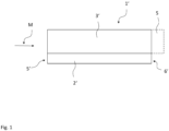
- FIG 1 shows a lateral view of a traditional heat sink device 1'.
- the heat sink device 1 comprises a base plate element 2'.
- the base plate element 2' has a rectangular cross-section perpendicular to the lateral viewing direction of Figure 1 .
- On the base plate element 2' a plurality of planar parallel first fin elements 3' is arranged, whereas in Figure 1 only a first fin element 3' is visible in viewing direction. Further planar fin elements 3' are arranged behind the visible first fin element 3' in lateral viewing direction (see Figure 2 ).
- Figure 1 shows a main flow direction M.
- the main flow direction M gives the direction in which a fluid is flowing and transporting heat received from the heat sink device 1', when the heat sink device 1' is in operation.
- the base plate element 2' of the heat sink device 1' comprises edges.
- the edge of the base plate element 2' positioned upstream relative to the main flow direction M is the leading edge 5' of the base plate element 2'.
- the edge of the base plate element 2' positioned downstream relative to the main flow direction M is the trailing edge 6'
- the leading edge 5' and the trailing edge 6' are arranged perpendicular to the main flow direction M.
- a technical device to be cooled can be positioned in thermal contact with the surface of the base plate element 2' opposite to the side where the first fin element 3' is arranged.
- Figure 2 shows the heat sink device 1' of Figure 1 from a top view. Here the plurality of planar first fin elements 3' is visible. Adjacent first fin elements 3' form a guiding channel for the fluid in main flow direction M.
- the technical device During operation the technical device, not shown in Figure 1 , generates heat loss. This heat generated by the technical device is transferred to the heat sink device 1', i.e. also the base plate element 2' and the planar first fin elements 3'.
- the heat energy is transferred from the heat sink device 1' to the fluid and transported away in main flow direction M.
- a fluid flow passing the heat sink device 1' shall mean that the fluid is guided such that it can receive thermal energy from the heat sink device. Especially the fluid can be in contact with the heat sink device 1'.
- a heat sink device 1' according to Figure 1 and Figure 2 is used as reference configuration to show the performance of a heat sink device according to the invention.
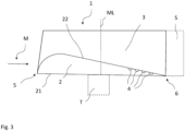
- Figure 3 shows a lateral view on an exemplary heat sink device 1 according to the invention.
- the heat sink device 1 comprises a base plate element 2 having an airfoil shape cross-section in a plane perpendicular to the lateral viewing direction. Further, the heat sink device 1 comprises a plurality sheet-like shaped first fin elements 3, whereas only the first sheet-like shaped first fin element 3 in lateral viewing direction is visible in Figure 3 .
- the base plate element 2 comprises a leading edge 5 and a trailing edge of the base plate element 2.
- the leading edge 5 that is the part of the base plate element 2 which gets first in contact with a fluid that streams in main flow direction M.
- the trailing edge 6 is the part of the base plate element 2, which is last in contact with the fluid that stream in main flow direction.
- the airfoil-shaped cross-section of the base plate element 2 is therefore also arranged in a plane perpendicular to the leading edge 5 and the trailing edge 6 of the base plate element 2.
- the leading edge 5 and the trailing edge 6 can be defined by a line, e.g. as in Figure 3 , or by a plane, e.g. in Figure 1 .
- the line defining the leading edge 5 and the trailing 6 edge are each and both parallel to the lateral viewing direction.
- the leading edge 5 and the trailing edge 6 are positioned perpendicular to the sheet-like shaped first fin element 3 defining a sheet plane S.
- the airfoil shape of the base plate element 2 is configured such that the surface 21 opposite to the surface 22, where the first fin elements 3 are arranged, is at least partly planar.
- the entire surface 21 of the base plate element 2 arranged opposite to the surface 22 of the base plate element comprising the plurality of first fin elements 3 is configured planar. This means that the so-called chord line, the shortest line between the leading edge and the trailing edge, is comprised by the surface 21 of the base plate element 2 directed away from the first fin elements 3.
- the first sheet-like shaped first fin element 3 rises from the leading edge 5 in an inclined way to given height, respectively width. According to Figure 3 , it can be a linear inclination. However, also a non-linear inclination is possible. The amount of the inclination can be varied as well. In a special embodiment the height of the sheet-like shaped first fin element 3 is held constant in main flow direction M relative to the surface 22 of the base plate element 2 directed towards the first fin elements 3.
- the heat sink device 1 comprises a plurality of bulges 4.
- Each bulge 4 is configured according to Figure 3 to have a are half-spherical recess, whereas the recess surface is part of the surface 22 of the base plate element 2 directed towards the plurality of first fin elements 3.
- the bulges 4 can also be shaped differently.
- the bulges 4 are arranged behind each other in main flow direction M, preferably in regular patterns, especially in equal distances.
- the bulges 4 can be arranged as patterns also in a lateral direction at the base plate element 2.
- a middle line ML is shown, which is the middle between the leading edge 5 and the trailing edge 6 of the base plate element 2.
- the plurality of bulges 4 is arranged between the middle line ML and the trailing edge 6.
- the size of the bulges 4 is selected such that in view of a selected fluid the bulges 4 create - during operation of the heat sink device 1 - vortices in a fluid flow passing the base plate element 2, whereas the bulges 4 are configured such that the vortices create for the given fluid flow an additional force pressing the fluid flow towards the surface 22.
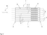
- Figure 4 shows a top view of the heat sink device 1 shown in Figure 3 .
- the plurality of sheet-like shaped first fin elements 3 can be seen from the top view.
- the sheet-like shaped first fin elements 3 are arranged parallel to each other and are perpendicular to the line defined by the leading edge 5 and trailing edge 6.
- Each guiding channel 9 comprises a plurality of bulges 4, whereas the plurality of bulges 4 are arranged symmetrically to a center plane E of a guiding channel 9.
- the center plane E is arranged in the middle between two adjacent sheet-like shaped first fin elements 3 and parallel to the two adjacent sheet-like shaped first fin elements 3.
- the fluid flows in main flow direction M towards the heat sink device 1, whereas a laminar flow is provided to the heat sink device 1.
- the airfoil shaped cross-section of the base plate element 2 leads to a stationary flow on the surfaces 22, 21 of the base plate element 2.
- Arranging the bulges 4 between the middle line ML of the base plate element 2 and the trailing edge 6 delays the flow separation for the base plate element 2, especially from the surface 22 in that area providing a better contact of the fluid to the surface 22 of the base element 2.
- the diameter of the bulges is advantageously 1/5 to 1/2 of the width of the guiding channel 9.
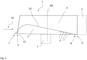
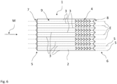
- Figure 5 and Figure 6 show a further improved version of the heat sink device 1 shown in Figure 3 and 4 .
- Figure 5 shows a lateral view and Figure 6 a top view of a heat sink device 1 comprising a tubercle 7 for each guiding channel 9 and an end fin element 8 for each guiding channel 9.
- the tubercles 7 and the end fin elements 8 are placed symmetrically to the center plane E.
- the tubercles 7 can preferably be comprised by the base plate element 2 or can be a separate unit arranged at the base plate element 2.
- the end fin elements 8 can be comprised by the base plate element 2 or can be arranged at the base plate element 2 as separate unit.
- the tubercles 7 create a controlled disturbance of the fluid flow when the fluid flow flows on the tubercle 7, i.e. before the airfoil shaped cross-section of the base plate element is reached.
- Each tubercle 7 creates vortices that generate a higher fluid density close to the surface 22 of the base plate element 2, especially in the respective guiding channel 9 following the tubercle 7 in main flow direction M.
- By the tubercles 7 further fluid channels are generated for the respective guiding channel 9, which increase the capacity of the fluid to receive heat energy from the base plate element 2. This further improves the cooling efficiency of the heat sink device 1.
- the end fin elements 8 have the function to guide the fluid flow at the leading edge efficiently away from the heat sink device 1 and to avoid turbulences close to the heat sink device 1 and lead away the heated fluid in an efficient way from the base plate element 2.
- Such a heat sink device 1 according to Figure 5 and 6 provides a decreased junction temperature of a diode (used as technical device) of roughly 15% compared to a heat sink device 1' according to Figure 1 and 2 under comparable conditions.
- the ambient temperature was 45 degree Celsius.
- a Diode TO-247 was used with a thermal conductance of 0.8K/W and a maximum junction temperature of 175 degree Celsius.
- the power dissipation was 2.0Watt
- the heat sink device was made from Aluminum, whereas the air flow was generated with a Fan Sunon PE60251BX.
- the junction temperature of the diode for a heat sink device 1' according to Figure 1 and 2 is 129,2 degree Celsius.
- the junction temperature of the diode for a heat sink device 1 according to Figure 5 and 6 is 110,2 degree Celsius This shows a drastically improved cooling efficiency of the heat sink device 1 according to the invention compared to the heat sink device 1' according to Figure 1 or Figure 2 .
- FIG. 7 shows a further modified exemplary embodiment of a heat sink device according to the invention in a lateral view.
- the heat sink device 1 according to Figure 7 further comprises second fin elements 10.
- the second fin elements 10 are arranged at the first fin elements 3 in different distances from the surface 22 of the base plate element 2 and can be arranged behind each other in main flow direction M.
- These second fin elements 10 have an airfoil cross-section in a plane parallel to sheet plane S of a sheet-like shaped first fin element 3, respectively in a plane perpendicular to the leading edge 5 and the trailing edge 6.
- the second fin elements 10 can comprise bulges similar to the bulges 4 of the base plate element 2.
- the second fin elements 10 improve the heat exchange between the heat sink device 1 for fluid streams more distant from the base plate element 2.
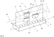
- FIG. 8 shows a section of an alternative configuration for a heat sink device 1 according to the invention.
- the shown section of the heat sink device 1 comprises a base plate element 2 on which a sheet-like shaped first fin element 3 is arranged.
- a plurality of first fin elements 10 can be arranged on the base plate element 2 .
- the shown sheet-like shaped first fin element 3 extends from the leading edge 5 to the trailing edge 6.
- the base plate element 2 In a plane perpendicular to the leading edge 5, respectively parallel to the sheet plane S of the sheet-like shaped first fin element 3, the base plate element 2 has a rectangular cross-section.
- the surface 22 of the base plate element 2 oriented towards the first fin element 3 comprises a plurality of bulges arranged behind each other in main flow direction M.
- second fin elements 10 are arranged at the shown first fin element 10.
- the second fin element 10 are arranged such that they have an airfoil shaped cross-section in a plane P perpendicular to the sheet plane S of the sheet-like shaped first in element 3, and parallel to the main flow direction Respectively this plane P is parallel to the surface 21 of the base plate element 2 facing away from the first fin elements 3.
- the second fin elements 10 can comprise one or more bulges that generate vortices in a fluid passing the second fin element 10 to generated a delayed flow separation also at second fin elements 10.
- a plurality of such arranged second fin elements 10 can be arranged at a first fin element 3, respectively at the plurality of first fin elements 10.
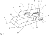
- the sheet-like shaped first fin element 3 according to Figure 9 comprises an opening 13, whose size essentially corresponds to the size of the second fin element 10.
- the opening 13 comprises an upstream boundary area 14 and a downstream boundary area 15 relative to the main flow direction M.
- the leading edge of the second fin element is part of the upstream boundary area of the opening 13.
- the first and second fin elements 3, 10, as shown in Figure 8 can be arranged at a base plate element 2 with an airfoil shaped cross-section in a plane parallel to the sheet-like shaped first fin element 3.
- the base plate element 2 comprises a plurality of bulges 4 between the middle of the base plate element 2 and the trailing edge 6.
- each of the second fin elements 10 can comprise bulges to delay the flow separation for each second fin element to further improve the heat transfer to the fluid.
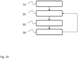
- FIG 10 shows a flow chart for a manufacturing method for a heat sink fin element.
- Such heat sink fin elements can be applied for the section of heat sink devices shown in Figure 8 and 9 .
- a metal sheet with a sheet plane is provided to a stamper unit. This metal sheet will be at a later stage the first fin element.
- a rectangular part of the metal sheet is cut with the stamper unit, whereas the part is still attached to the metal sheet.
- the part is still attached to the metal sheet.
- the cut part can also have other forms than a rectangular form. The cut part will become the second fin element.
- a method step S3 the cut part is pressed, as part of the stamping, such by the stamper unit that the cut part receives an airfoil-shaped cross-section configured to be in a plane perpendicular to the sheet plane and parallel to the main flow direction when installed in a heat sink device.
- bulges can be generated on the surface of the cut part, which is supposed to face away from the sheet plan from which it originates.
- the cut and stamped part is formed with the stamper unit such that the part is partly arranged outside the sheet plane and partly inside the sheet plane.
- the cut and stamped part comprises a leading edge and a trailing edge in a main flow direction, whereas the cut and stamped part is stamped such that the leading edge is attached to the sheet and the trailing edge is arranged distant from the sheet plane.
- a first fin element comprising at least one second fin element having an airfoil-shaped cross-section in a plane perpendicular to the sheet plane and parallel to a later main flow direction.
- the method steps S2 to S4 can be repeated for different positions of the metal sheet until a desired number of second fin elements have been manufactured for a first fin element.
- a plurality of second fin elements is created, especially in parallel, on and from the metal sheet.
- the method steps S2 to S4 can also be changed in its order or summarized into one or more steps.
- the metal sheet especially a plurality of metal sheets, comprising such stamped second fin elements can be arranged on a base plate element, especially a base plate element comprising an airfoil-shaped section.
- Such stamped second fin elements in conjunctions with the opening of the first fin element provide an advantageous fluid flow for a heat sink device comprising such first and second fin elements.
- These heat sink fin elements are easy to manufacture and significantly improve cooling efficiency for a heat sink device.
Landscapes
- Engineering & Computer Science (AREA)
- Mechanical Engineering (AREA)
- Physics & Mathematics (AREA)
- Thermal Sciences (AREA)
- General Engineering & Computer Science (AREA)
- Cooling Or The Like Of Electrical Apparatus (AREA)
Claims (13)
- Kühlkörpervorrichtung (1), umfassend ein Grundplattenelement (2), ein an dem Grundplattenelement (2) angeordnetes erstes Rippenelement (3), wobei mindestens eines aus der Gruppe aus dem Grundplattenelement (2) und dem ersten Rippenelement (3) einen tragflächenförmigen Querschnitt aufweist, während das Grundplattenelement (2) mindestens eine Ausbuchtung (4) aufweist, die dazu konfiguriert ist, in einem an dem Grundplattenelement (2) vorbeiströmenden Fluidstrom Wirbel zu erzeugen;
dadurch gekennzeichnet, dass
das Grundplattenelement (2) einen tragflächenförmigen Querschnitt aufweist, der sich in einer Hauptströmungsrichtung (M) von einer Vorderkante (5) zu einer Hinterkante (6) des Grundplattenelements (2) erstreckt. - Kühlkörpervorrichtung nach Anspruch 1,
wobei das Grundplattenelement (2) eine Vielzahl von Ausbuchtungen (4) umfasst, die dazu ausgebildet sind, in einer an dem Grundplattenelement (2) vorbeiströmenden Fluidströmung Wirbel zu erzeugen, wobei die von der Vielzahl von Ausbuchtungen (4) umfassten Ausbuchtungen in der Hauptströmungsrichtung (M) hintereinander angeordnet sind. - Kühlkörpervorrichtung nach Anspruch 1 oder 2,
wobei das Grundplattenelement (2) eine Mittellinie (ML) umfasst, die die Mitte zwischen der Vorderkante (5) und der Hinterkante (6) definiert, wobei die mindestens eine Ausbuchtung (4) zwischen der Mittellinie (ML) und der Hinterkante (6) angeordnet ist. - Kühlkörpervorrichtung nach Anspruch 2 oder 3,
wobei das erste Rippenelement (3) eine blattartige Form aufweist, die eine Blattebene (S) definiert, wobei die Blattebene (S) senkrecht zur Vorderkante (5) und/oder parallel zur Hauptströmungsrichtung (M) angeordnet ist. - Kühlkörpervorrichtung nach Anspruch 4,
wobei eine Vielzahl blattförmiger erster Rippenelemente (3) parallel zur Hauptströmungsrichtung (M) und/oder senkrecht auf der Vorderkante (5) angeordnet ist, wobei benachbarte blattartig geformte erste Rippenelemente (3) einen Führungskanal (9) zum Führen einer Fluidströmung in einer Hauptströmungsrichtung (M) bilden. - Kühlkörpervorrichtung nach Anspruch 5,
wobei sich mindestens ein Führungskanal (9) bis zur Vorderkante (5) erstreckt, wobei die Vorderkante (5) für den mindestens einen Führungskanal (9) einen symmetrisch zu einer Mittelebene (E) des Führungskanals (9) angeordnete Wölbung (7) aufweist, wobei die Mittelebene (E) parallel zu benachbarten Blattebenen (S) ausgerichtet und mittig zwischen diesen angeordnet ist. - Kühlkörpervorrichtung nach Anspruch 5 oder 6,
wobei sich mindestens ein Führungskanal (9) bis zur Hinterkante (6) erstreckt, wobei die Hinterkante (6) für den mindestens einen Führungskanal (9) ein symmetrisch zur Mittelebene (E) des Führungskanals (9) angeordnetes Endrippenelement (8) aufweist, wobei die Mittelebene (E) parallel zu benachbarten Blattebenen ausgerichtet und mittig zwischen diesen angeordnet ist. - Kühlkörpervorrichtung nach einem der Ansprüche 5 bis 7,
wobei eine Vielzahl von Ausbuchtungen (4) in Hauptströmungsrichtung (M) hintereinander angeordnet ist, wobei die Vielzahl von Ausbuchtungen (4) innerhalb mindestens eines Führungskanals (9) angeordnet ist. - Kühlkörpervorrichtung nach einem der vorhergehenden Ansprüche, die ferner ein zweites Rippenelement (10) umfasst,
wobei das zweite Rippenelement (10) am ersten Rippenelement (3) angeordnet ist, wobei das zweite Rippenelement (10) so angeordnet ist, dass es in einer Ebene senkrecht zur Vorderkante (5) und parallel zur Hauptströmungsrichtung (M) einen tragflächenförmigen Querschnitt aufweist. - Kühlkörpervorrichtung nach Anspruch 9,
wobei mindestens eines aus der Gruppe des ersten Rippenelements (3) und eines am ersten Rippenelement (3) angeordneten zweiten Rippenelements (10) so konfiguriert ist, dass es einen tragflächenförmigen Querschnitt in einer Ebene (P) aufweist, die parallel zur Vorderkante des Basisplattenelements (2) und parallel zur Hauptströmungsrichtung (M) verläuft. - Kühlkörpervorrichtung nach Anspruch 10,
wobei das erste Rippenelement (3) eine blattartige Form aufweist, die eine Blattebene (S) definiert, wobei die Blattebene (S) senkrecht zur Vorderkante (5) und/oder senkrecht zur Hinterkante (6) des Basisplattenelements (2) angeordnet ist, wobei das zweite Rippenelement einen tragflächenförmigen Querschnitt in einer Ebene (P) aufweist, die parallel zur Vorderkante des Basisplattenelements (2) und parallel zur Hauptströmungsrichtung (M) verläuft, wobei das zweite Rippenelement (10) teilweise außerhalb der Blattebene (S) des ersten Rippenelements (3) angeordnet ist. - Kühlkörpervorrichtung nach Anspruch 11,
wobei eine Vorderkante (11) des zweiten Rippenelements (10) an dem ersten Rippenelement (3) befestigt ist und die Vorderkante (12) des zweiten Rippenelements (10) von der Blattebene (S) entfernt positioniert ist. - Kühlkörpervorrichtung nach einem der Ansprüche 10 bis 12,
wobei das erste Rippenelement (3) eine Öffnung (13) umfasst, deren Größe der Größe des zweiten Rippenelements (10) entspricht, wobei die Öffnung (13) einen in Hauptströmungsrichtung (M) stromaufwärtigen Begrenzungsbereich (14) und einen in Hauptströmungsrichtung (M) stromabwärtigen Begrenzungsbereich (15) aufweist, wobei die Vorderkante (5) des zweiten Rippenelements (10) Teil des stromaufwärtigen Begrenzungsbereichs (14) ist.
Priority Applications (1)
| Application Number | Priority Date | Filing Date | Title |
|---|---|---|---|
| EP21197755.8A EP4151945B1 (de) | 2021-09-20 | 2021-09-20 | Kühlkörper und herstellungsverfahren für ein kühlkörperrippenelement |
Applications Claiming Priority (1)
| Application Number | Priority Date | Filing Date | Title |
|---|---|---|---|
| EP21197755.8A EP4151945B1 (de) | 2021-09-20 | 2021-09-20 | Kühlkörper und herstellungsverfahren für ein kühlkörperrippenelement |
Publications (2)
| Publication Number | Publication Date |
|---|---|
| EP4151945A1 EP4151945A1 (de) | 2023-03-22 |
| EP4151945B1 true EP4151945B1 (de) | 2025-06-04 |
Family
ID=77914245
Family Applications (1)
| Application Number | Title | Priority Date | Filing Date |
|---|---|---|---|
| EP21197755.8A Active EP4151945B1 (de) | 2021-09-20 | 2021-09-20 | Kühlkörper und herstellungsverfahren für ein kühlkörperrippenelement |
Country Status (1)
| Country | Link |
|---|---|
| EP (1) | EP4151945B1 (de) |
Family Cites Families (9)
| Publication number | Priority date | Publication date | Assignee | Title |
|---|---|---|---|---|
| US5823249A (en) | 1997-09-03 | 1998-10-20 | Batchelder; John Samual | Manifold for controlling interdigitated counterstreaming fluid flows |
| US6201699B1 (en) * | 1999-03-01 | 2001-03-13 | Lucent Technologies Inc. | Transverse mountable heat sink for use in an electronic device |
| US20080066888A1 (en) * | 2006-09-08 | 2008-03-20 | Danaher Motion Stockholm Ab | Heat sink |
| US20090321056A1 (en) * | 2008-03-11 | 2009-12-31 | Tessera, Inc. | Multi-stage electrohydrodynamic fluid accelerator apparatus |
| US8552485B2 (en) | 2011-06-15 | 2013-10-08 | Taiwan Semiconductor Manufacturing Company, Ltd. | Semiconductor structure having metal-insulator-metal capacitor structure |
| US20140151010A1 (en) * | 2012-12-03 | 2014-06-05 | Tyco Electronics Corporation | Heat sink |
| DE102015205902A1 (de) * | 2015-04-01 | 2016-10-06 | Mahle International Gmbh | Rippe für einen Wärmeübertrager |
| WO2020232178A1 (en) | 2019-05-14 | 2020-11-19 | Holo, Inc. | Devices, systems and methods for thermal management |
| EP3813098B1 (de) * | 2019-10-25 | 2025-12-03 | ABB Schweiz AG | Dampfkammer |
-
2021
- 2021-09-20 EP EP21197755.8A patent/EP4151945B1/de active Active
Also Published As
| Publication number | Publication date |
|---|---|
| EP4151945A1 (de) | 2023-03-22 |
Similar Documents
| Publication | Publication Date | Title |
|---|---|---|
| Wong et al. | Convective heat transfer and pressure losses across novel heat sinks fabricated by Selective Laser Melting | |
| US10703490B2 (en) | Method and apparatus for heat-dissipation in electronics | |
| US7545645B2 (en) | Heat dissipation device | |
| US20080066888A1 (en) | Heat sink | |
| Sadeghianjahromi et al. | Heat transfer enhancement of wavy fin-and-tube heat exchangers via innovative compound designs | |
| US8381800B2 (en) | Heat dissipation device with triangular guiding member | |
| US20140262194A1 (en) | Flow diverters to enhance heat sink performance | |
| CN101641005B (zh) | 散热装置 | |
| EP2853851B1 (de) | Reduzierung der Wärmeermüdungsbelastung eines Wärmetauschers | |
| Ismail | Effects of perforations on the thermal and fluid dynamic performance of a heat exchanger | |
| EP4151945B1 (de) | Kühlkörper und herstellungsverfahren für ein kühlkörperrippenelement | |
| Abdelkareem et al. | Enhancement of a heat sink performance using a partial shield and/or a guide plate | |
| Pallikonda et al. | Heat transfer enhancement using elliptical fin microchannel | |
| Lu et al. | Microelectronic chip cooling: an experimental assessment of a liquid-passing heat sink, a microchannel heat rejection module, and a microchannel-based recirculating-liquid cooling system | |
| CN104218011A (zh) | 微处理器散热系统 | |
| CN114396662A (zh) | 电控盒和具有其的空调室外机 | |
| Khan et al. | Performance of shrouded pin-fin heat sinks for electronic cooling | |
| KR101422187B1 (ko) | 냉각장치 내부냉각유로의 내면에 부착되는 핀-휜의 새로운 형상 구조 | |
| CN207486521U (zh) | 光模块 | |
| EP3240376B1 (de) | Schrank | |
| Song et al. | Numerical study of heat transfer enhancement of finned flat tube bank fin with vortex generators mounted on both surfaces of the fin | |
| Gaıkwad et al. | Enhancement in thermo-hydraulic performance of microchannel heat sink with secondary flows of leaf venation pattern | |
| Kong et al. | Innovation design of heatsink: A comparative study on heatsink structure analysis in power electronics | |
| Tang et al. | Heat transfer enhancement and flow characteristics of internal cooling channels with slit vortex generators | |
| Baruah et al. | Effect of longitudinal and lateral holes on the performance of an elliptical pin fin heat exchanger |
Legal Events
| Date | Code | Title | Description |
|---|---|---|---|
| PUAI | Public reference made under article 153(3) epc to a published international application that has entered the european phase |
Free format text: ORIGINAL CODE: 0009012 |
|
| STAA | Information on the status of an ep patent application or granted ep patent |
Free format text: STATUS: THE APPLICATION HAS BEEN PUBLISHED |
|
| AK | Designated contracting states |
Kind code of ref document: A1 Designated state(s): AL AT BE BG CH CY CZ DE DK EE ES FI FR GB GR HR HU IE IS IT LI LT LU LV MC MK MT NL NO PL PT RO RS SE SI SK SM TR |
|
| P01 | Opt-out of the competence of the unified patent court (upc) registered |
Effective date: 20230525 |
|
| STAA | Information on the status of an ep patent application or granted ep patent |
Free format text: STATUS: REQUEST FOR EXAMINATION WAS MADE |
|
| 17P | Request for examination filed |
Effective date: 20230915 |
|
| RBV | Designated contracting states (corrected) |
Designated state(s): AL AT BE BG CH CY CZ DE DK EE ES FI FR GB GR HR HU IE IS IT LI LT LU LV MC MK MT NL NO PL PT RO RS SE SI SK SM TR |
|
| GRAP | Despatch of communication of intention to grant a patent |
Free format text: ORIGINAL CODE: EPIDOSNIGR1 |
|
| STAA | Information on the status of an ep patent application or granted ep patent |
Free format text: STATUS: GRANT OF PATENT IS INTENDED |
|
| RIC1 | Information provided on ipc code assigned before grant |
Ipc: F28F 13/08 20060101ALN20250131BHEP Ipc: F28F 13/02 20060101ALN20250131BHEP Ipc: F28F 3/04 20060101ALN20250131BHEP Ipc: H01L 23/34 20060101ALI20250131BHEP Ipc: F28F 3/02 20060101AFI20250131BHEP |
|
| INTG | Intention to grant announced |
Effective date: 20250213 |
|
| GRAS | Grant fee paid |
Free format text: ORIGINAL CODE: EPIDOSNIGR3 |
|
| GRAA | (expected) grant |
Free format text: ORIGINAL CODE: 0009210 |
|
| STAA | Information on the status of an ep patent application or granted ep patent |
Free format text: STATUS: THE PATENT HAS BEEN GRANTED |
|
| RBV | Designated contracting states (corrected) |
Designated state(s): AL AT BE BG CY CZ DE DK EE ES FI FR GB GR HR HU IS IT LT LU LV MC MK MT NL NO PL PT RO RS SE SI SK SM TR |
|
| AK | Designated contracting states |
Kind code of ref document: B1 Designated state(s): AL AT BE BG CY CZ DE DK EE ES FI FR GB GR HR HU IS IT LT LU LV MC MK MT NL NO PL PT RO RS SE SI SK SM TR |
|
| REG | Reference to a national code |
Ref country code: GB Ref legal event code: FG4D |
|
| REG | Reference to a national code |
Ref country code: DE Ref legal event code: R096 Ref document number: 602021031660 Country of ref document: DE |
|
| REG | Reference to a national code |
Ref country code: NL Ref legal event code: MP Effective date: 20250604 |
|
| PG25 | Lapsed in a contracting state [announced via postgrant information from national office to epo] |
Ref country code: FI Free format text: LAPSE BECAUSE OF FAILURE TO SUBMIT A TRANSLATION OF THE DESCRIPTION OR TO PAY THE FEE WITHIN THE PRESCRIBED TIME-LIMIT Effective date: 20250604 Ref country code: ES Free format text: LAPSE BECAUSE OF FAILURE TO SUBMIT A TRANSLATION OF THE DESCRIPTION OR TO PAY THE FEE WITHIN THE PRESCRIBED TIME-LIMIT Effective date: 20250604 |
|
| PGFP | Annual fee paid to national office [announced via postgrant information from national office to epo] |
Ref country code: DE Payment date: 20250919 Year of fee payment: 5 |
|
| REG | Reference to a national code |
Ref country code: LT Ref legal event code: MG9D |
|
| PG25 | Lapsed in a contracting state [announced via postgrant information from national office to epo] |
Ref country code: NO Free format text: LAPSE BECAUSE OF FAILURE TO SUBMIT A TRANSLATION OF THE DESCRIPTION OR TO PAY THE FEE WITHIN THE PRESCRIBED TIME-LIMIT Effective date: 20250904 Ref country code: GR Free format text: LAPSE BECAUSE OF FAILURE TO SUBMIT A TRANSLATION OF THE DESCRIPTION OR TO PAY THE FEE WITHIN THE PRESCRIBED TIME-LIMIT Effective date: 20250905 |
|
| PG25 | Lapsed in a contracting state [announced via postgrant information from national office to epo] |
Ref country code: PL Free format text: LAPSE BECAUSE OF FAILURE TO SUBMIT A TRANSLATION OF THE DESCRIPTION OR TO PAY THE FEE WITHIN THE PRESCRIBED TIME-LIMIT Effective date: 20250604 |
|
| PG25 | Lapsed in a contracting state [announced via postgrant information from national office to epo] |
Ref country code: BG Free format text: LAPSE BECAUSE OF FAILURE TO SUBMIT A TRANSLATION OF THE DESCRIPTION OR TO PAY THE FEE WITHIN THE PRESCRIBED TIME-LIMIT Effective date: 20250604 |
|
| PGFP | Annual fee paid to national office [announced via postgrant information from national office to epo] |
Ref country code: GB Payment date: 20250923 Year of fee payment: 5 |
|
| PG25 | Lapsed in a contracting state [announced via postgrant information from national office to epo] |
Ref country code: HR Free format text: LAPSE BECAUSE OF FAILURE TO SUBMIT A TRANSLATION OF THE DESCRIPTION OR TO PAY THE FEE WITHIN THE PRESCRIBED TIME-LIMIT Effective date: 20250604 |
|
| PGFP | Annual fee paid to national office [announced via postgrant information from national office to epo] |
Ref country code: FR Payment date: 20250926 Year of fee payment: 5 Ref country code: AT Payment date: 20251020 Year of fee payment: 5 |
|
| PG25 | Lapsed in a contracting state [announced via postgrant information from national office to epo] |
Ref country code: RS Free format text: LAPSE BECAUSE OF FAILURE TO SUBMIT A TRANSLATION OF THE DESCRIPTION OR TO PAY THE FEE WITHIN THE PRESCRIBED TIME-LIMIT Effective date: 20250904 |
|
| PG25 | Lapsed in a contracting state [announced via postgrant information from national office to epo] |
Ref country code: LV Free format text: LAPSE BECAUSE OF FAILURE TO SUBMIT A TRANSLATION OF THE DESCRIPTION OR TO PAY THE FEE WITHIN THE PRESCRIBED TIME-LIMIT Effective date: 20250604 |
|
| PG25 | Lapsed in a contracting state [announced via postgrant information from national office to epo] |
Ref country code: NL Free format text: LAPSE BECAUSE OF FAILURE TO SUBMIT A TRANSLATION OF THE DESCRIPTION OR TO PAY THE FEE WITHIN THE PRESCRIBED TIME-LIMIT Effective date: 20250604 |
|
| PG25 | Lapsed in a contracting state [announced via postgrant information from national office to epo] |
Ref country code: PT Free format text: LAPSE BECAUSE OF FAILURE TO SUBMIT A TRANSLATION OF THE DESCRIPTION OR TO PAY THE FEE WITHIN THE PRESCRIBED TIME-LIMIT Effective date: 20251006 |
|
| REG | Reference to a national code |
Ref country code: AT Ref legal event code: MK05 Ref document number: 1800696 Country of ref document: AT Kind code of ref document: T Effective date: 20250604 |
|
| PG25 | Lapsed in a contracting state [announced via postgrant information from national office to epo] |
Ref country code: IS Free format text: LAPSE BECAUSE OF FAILURE TO SUBMIT A TRANSLATION OF THE DESCRIPTION OR TO PAY THE FEE WITHIN THE PRESCRIBED TIME-LIMIT Effective date: 20251004 |
|
| PG25 | Lapsed in a contracting state [announced via postgrant information from national office to epo] |
Ref country code: SM Free format text: LAPSE BECAUSE OF FAILURE TO SUBMIT A TRANSLATION OF THE DESCRIPTION OR TO PAY THE FEE WITHIN THE PRESCRIBED TIME-LIMIT Effective date: 20250604 Ref country code: AT Free format text: LAPSE BECAUSE OF FAILURE TO SUBMIT A TRANSLATION OF THE DESCRIPTION OR TO PAY THE FEE WITHIN THE PRESCRIBED TIME-LIMIT Effective date: 20250604 |
|
| PG25 | Lapsed in a contracting state [announced via postgrant information from national office to epo] |
Ref country code: CZ Free format text: LAPSE BECAUSE OF FAILURE TO SUBMIT A TRANSLATION OF THE DESCRIPTION OR TO PAY THE FEE WITHIN THE PRESCRIBED TIME-LIMIT Effective date: 20250604 |
|
| PG25 | Lapsed in a contracting state [announced via postgrant information from national office to epo] |
Ref country code: EE Free format text: LAPSE BECAUSE OF FAILURE TO SUBMIT A TRANSLATION OF THE DESCRIPTION OR TO PAY THE FEE WITHIN THE PRESCRIBED TIME-LIMIT Effective date: 20250604 |
|
| PG25 | Lapsed in a contracting state [announced via postgrant information from national office to epo] |
Ref country code: SK Free format text: LAPSE BECAUSE OF FAILURE TO SUBMIT A TRANSLATION OF THE DESCRIPTION OR TO PAY THE FEE WITHIN THE PRESCRIBED TIME-LIMIT Effective date: 20250604 |
|
| PG25 | Lapsed in a contracting state [announced via postgrant information from national office to epo] |
Ref country code: IT Free format text: LAPSE BECAUSE OF FAILURE TO SUBMIT A TRANSLATION OF THE DESCRIPTION OR TO PAY THE FEE WITHIN THE PRESCRIBED TIME-LIMIT Effective date: 20250604 |
|
| PG25 | Lapsed in a contracting state [announced via postgrant information from national office to epo] |
Ref country code: RO Free format text: LAPSE BECAUSE OF FAILURE TO SUBMIT A TRANSLATION OF THE DESCRIPTION OR TO PAY THE FEE WITHIN THE PRESCRIBED TIME-LIMIT Effective date: 20250604 |