EP4151915A1 - Heating control device and heating control program - Google Patents
Heating control device and heating control program Download PDFInfo
- Publication number
- EP4151915A1 EP4151915A1 EP20935466.1A EP20935466A EP4151915A1 EP 4151915 A1 EP4151915 A1 EP 4151915A1 EP 20935466 A EP20935466 A EP 20935466A EP 4151915 A1 EP4151915 A1 EP 4151915A1
- Authority
- EP
- European Patent Office
- Prior art keywords
- heating control
- outside air
- temperature
- condensation temperature
- humidity
- Prior art date
- Legal status (The legal status is an assumption and is not a legal conclusion. Google has not performed a legal analysis and makes no representation as to the accuracy of the status listed.)
- Withdrawn
Links
Images




Classifications
-
- F—MECHANICAL ENGINEERING; LIGHTING; HEATING; WEAPONS; BLASTING
- F24—HEATING; RANGES; VENTILATING
- F24F—AIR-CONDITIONING; AIR-HUMIDIFICATION; VENTILATION; USE OF AIR CURRENTS FOR SCREENING
- F24F12/00—Use of energy recovery systems in air conditioning, ventilation or screening
- F24F12/001—Use of energy recovery systems in air conditioning, ventilation or screening with heat-exchange between supplied and exhausted air
- F24F12/006—Use of energy recovery systems in air conditioning, ventilation or screening with heat-exchange between supplied and exhausted air using an air-to-air heat exchanger
-
- F—MECHANICAL ENGINEERING; LIGHTING; HEATING; WEAPONS; BLASTING
- F24—HEATING; RANGES; VENTILATING
- F24F—AIR-CONDITIONING; AIR-HUMIDIFICATION; VENTILATION; USE OF AIR CURRENTS FOR SCREENING
- F24F11/00—Control or safety arrangements
- F24F11/70—Control systems characterised by their outputs; Constructional details thereof
- F24F11/80—Control systems characterised by their outputs; Constructional details thereof for controlling the temperature of the supplied air
- F24F11/86—Control systems characterised by their outputs; Constructional details thereof for controlling the temperature of the supplied air by controlling compressors within refrigeration or heat pump circuits
-
- F—MECHANICAL ENGINEERING; LIGHTING; HEATING; WEAPONS; BLASTING
- F24—HEATING; RANGES; VENTILATING
- F24F—AIR-CONDITIONING; AIR-HUMIDIFICATION; VENTILATION; USE OF AIR CURRENTS FOR SCREENING
- F24F11/00—Control or safety arrangements
- F24F11/0001—Control or safety arrangements for ventilation
-
- F—MECHANICAL ENGINEERING; LIGHTING; HEATING; WEAPONS; BLASTING
- F24—HEATING; RANGES; VENTILATING
- F24F—AIR-CONDITIONING; AIR-HUMIDIFICATION; VENTILATION; USE OF AIR CURRENTS FOR SCREENING
- F24F7/00—Ventilation
- F24F7/04—Ventilation with ducting systems, e.g. by double walls; with natural circulation
- F24F7/06—Ventilation with ducting systems, e.g. by double walls; with natural circulation with forced air circulation, e.g. by fan positioning of a ventilator in or against a conduit
-
- F—MECHANICAL ENGINEERING; LIGHTING; HEATING; WEAPONS; BLASTING
- F25—REFRIGERATION OR COOLING; COMBINED HEATING AND REFRIGERATION SYSTEMS; HEAT PUMP SYSTEMS; MANUFACTURE OR STORAGE OF ICE; LIQUEFACTION SOLIDIFICATION OF GASES
- F25B—REFRIGERATION MACHINES, PLANTS OR SYSTEMS; COMBINED HEATING AND REFRIGERATION SYSTEMS; HEAT PUMP SYSTEMS
- F25B13/00—Compression machines, plants or systems, with reversible cycle
-
- F—MECHANICAL ENGINEERING; LIGHTING; HEATING; WEAPONS; BLASTING
- F25—REFRIGERATION OR COOLING; COMBINED HEATING AND REFRIGERATION SYSTEMS; HEAT PUMP SYSTEMS; MANUFACTURE OR STORAGE OF ICE; LIQUEFACTION SOLIDIFICATION OF GASES
- F25B—REFRIGERATION MACHINES, PLANTS OR SYSTEMS; COMBINED HEATING AND REFRIGERATION SYSTEMS; HEAT PUMP SYSTEMS
- F25B30/00—Heat pumps
- F25B30/02—Heat pumps of the compression type
-
- F—MECHANICAL ENGINEERING; LIGHTING; HEATING; WEAPONS; BLASTING
- F25—REFRIGERATION OR COOLING; COMBINED HEATING AND REFRIGERATION SYSTEMS; HEAT PUMP SYSTEMS; MANUFACTURE OR STORAGE OF ICE; LIQUEFACTION SOLIDIFICATION OF GASES
- F25B—REFRIGERATION MACHINES, PLANTS OR SYSTEMS; COMBINED HEATING AND REFRIGERATION SYSTEMS; HEAT PUMP SYSTEMS
- F25B49/00—Arrangement or mounting of control or safety devices
- F25B49/02—Arrangement or mounting of control or safety devices for compression type machines, plants or systems
-
- F—MECHANICAL ENGINEERING; LIGHTING; HEATING; WEAPONS; BLASTING
- F25—REFRIGERATION OR COOLING; COMBINED HEATING AND REFRIGERATION SYSTEMS; HEAT PUMP SYSTEMS; MANUFACTURE OR STORAGE OF ICE; LIQUEFACTION SOLIDIFICATION OF GASES
- F25B—REFRIGERATION MACHINES, PLANTS OR SYSTEMS; COMBINED HEATING AND REFRIGERATION SYSTEMS; HEAT PUMP SYSTEMS
- F25B49/00—Arrangement or mounting of control or safety devices
- F25B49/02—Arrangement or mounting of control or safety devices for compression type machines, plants or systems
- F25B49/022—Compressor control arrangements
-
- F—MECHANICAL ENGINEERING; LIGHTING; HEATING; WEAPONS; BLASTING
- F25—REFRIGERATION OR COOLING; COMBINED HEATING AND REFRIGERATION SYSTEMS; HEAT PUMP SYSTEMS; MANUFACTURE OR STORAGE OF ICE; LIQUEFACTION SOLIDIFICATION OF GASES
- F25B—REFRIGERATION MACHINES, PLANTS OR SYSTEMS; COMBINED HEATING AND REFRIGERATION SYSTEMS; HEAT PUMP SYSTEMS
- F25B49/00—Arrangement or mounting of control or safety devices
- F25B49/02—Arrangement or mounting of control or safety devices for compression type machines, plants or systems
- F25B49/027—Condenser control arrangements
-
- F—MECHANICAL ENGINEERING; LIGHTING; HEATING; WEAPONS; BLASTING
- F24—HEATING; RANGES; VENTILATING
- F24F—AIR-CONDITIONING; AIR-HUMIDIFICATION; VENTILATION; USE OF AIR CURRENTS FOR SCREENING
- F24F11/00—Control or safety arrangements
- F24F11/0001—Control or safety arrangements for ventilation
- F24F2011/0002—Control or safety arrangements for ventilation for admittance of outside air
-
- F—MECHANICAL ENGINEERING; LIGHTING; HEATING; WEAPONS; BLASTING
- F24—HEATING; RANGES; VENTILATING
- F24F—AIR-CONDITIONING; AIR-HUMIDIFICATION; VENTILATION; USE OF AIR CURRENTS FOR SCREENING
- F24F2110/00—Control inputs relating to air properties
- F24F2110/10—Temperature
-
- F—MECHANICAL ENGINEERING; LIGHTING; HEATING; WEAPONS; BLASTING
- F24—HEATING; RANGES; VENTILATING
- F24F—AIR-CONDITIONING; AIR-HUMIDIFICATION; VENTILATION; USE OF AIR CURRENTS FOR SCREENING
- F24F2110/00—Control inputs relating to air properties
- F24F2110/10—Temperature
- F24F2110/12—Temperature of the outside air
-
- F—MECHANICAL ENGINEERING; LIGHTING; HEATING; WEAPONS; BLASTING
- F24—HEATING; RANGES; VENTILATING
- F24F—AIR-CONDITIONING; AIR-HUMIDIFICATION; VENTILATION; USE OF AIR CURRENTS FOR SCREENING
- F24F2110/00—Control inputs relating to air properties
- F24F2110/20—Humidity
- F24F2110/22—Humidity of the outside air
-
- F—MECHANICAL ENGINEERING; LIGHTING; HEATING; WEAPONS; BLASTING
- F24—HEATING; RANGES; VENTILATING
- F24F—AIR-CONDITIONING; AIR-HUMIDIFICATION; VENTILATION; USE OF AIR CURRENTS FOR SCREENING
- F24F2120/00—Control inputs relating to users or occupants
- F24F2120/10—Occupancy
-
- F—MECHANICAL ENGINEERING; LIGHTING; HEATING; WEAPONS; BLASTING
- F24—HEATING; RANGES; VENTILATING
- F24F—AIR-CONDITIONING; AIR-HUMIDIFICATION; VENTILATION; USE OF AIR CURRENTS FOR SCREENING
- F24F2120/00—Control inputs relating to users or occupants
- F24F2120/10—Occupancy
- F24F2120/12—Position of occupants
-
- F—MECHANICAL ENGINEERING; LIGHTING; HEATING; WEAPONS; BLASTING
- F25—REFRIGERATION OR COOLING; COMBINED HEATING AND REFRIGERATION SYSTEMS; HEAT PUMP SYSTEMS; MANUFACTURE OR STORAGE OF ICE; LIQUEFACTION SOLIDIFICATION OF GASES
- F25B—REFRIGERATION MACHINES, PLANTS OR SYSTEMS; COMBINED HEATING AND REFRIGERATION SYSTEMS; HEAT PUMP SYSTEMS
- F25B2313/00—Compression machines, plants or systems with reversible cycle not otherwise provided for
- F25B2313/023—Compression machines, plants or systems with reversible cycle not otherwise provided for using multiple indoor units
- F25B2313/0233—Compression machines, plants or systems with reversible cycle not otherwise provided for using multiple indoor units in parallel arrangements
-
- F—MECHANICAL ENGINEERING; LIGHTING; HEATING; WEAPONS; BLASTING
- F25—REFRIGERATION OR COOLING; COMBINED HEATING AND REFRIGERATION SYSTEMS; HEAT PUMP SYSTEMS; MANUFACTURE OR STORAGE OF ICE; LIQUEFACTION SOLIDIFICATION OF GASES
- F25B—REFRIGERATION MACHINES, PLANTS OR SYSTEMS; COMBINED HEATING AND REFRIGERATION SYSTEMS; HEAT PUMP SYSTEMS
- F25B2313/00—Compression machines, plants or systems with reversible cycle not otherwise provided for
- F25B2313/031—Sensor arrangements
- F25B2313/0314—Temperature sensors near the indoor heat exchanger
-
- F—MECHANICAL ENGINEERING; LIGHTING; HEATING; WEAPONS; BLASTING
- F25—REFRIGERATION OR COOLING; COMBINED HEATING AND REFRIGERATION SYSTEMS; HEAT PUMP SYSTEMS; MANUFACTURE OR STORAGE OF ICE; LIQUEFACTION SOLIDIFICATION OF GASES
- F25B—REFRIGERATION MACHINES, PLANTS OR SYSTEMS; COMBINED HEATING AND REFRIGERATION SYSTEMS; HEAT PUMP SYSTEMS
- F25B2600/00—Control issues
- F25B2600/17—Control issues by controlling the pressure of the condenser
-
- F—MECHANICAL ENGINEERING; LIGHTING; HEATING; WEAPONS; BLASTING
- F25—REFRIGERATION OR COOLING; COMBINED HEATING AND REFRIGERATION SYSTEMS; HEAT PUMP SYSTEMS; MANUFACTURE OR STORAGE OF ICE; LIQUEFACTION SOLIDIFICATION OF GASES
- F25B—REFRIGERATION MACHINES, PLANTS OR SYSTEMS; COMBINED HEATING AND REFRIGERATION SYSTEMS; HEAT PUMP SYSTEMS
- F25B2600/00—Control issues
- F25B2600/19—Refrigerant outlet condenser temperature
-
- F—MECHANICAL ENGINEERING; LIGHTING; HEATING; WEAPONS; BLASTING
- F25—REFRIGERATION OR COOLING; COMBINED HEATING AND REFRIGERATION SYSTEMS; HEAT PUMP SYSTEMS; MANUFACTURE OR STORAGE OF ICE; LIQUEFACTION SOLIDIFICATION OF GASES
- F25B—REFRIGERATION MACHINES, PLANTS OR SYSTEMS; COMBINED HEATING AND REFRIGERATION SYSTEMS; HEAT PUMP SYSTEMS
- F25B2700/00—Sensing or detecting of parameters; Sensors therefor
- F25B2700/02—Humidity
-
- F—MECHANICAL ENGINEERING; LIGHTING; HEATING; WEAPONS; BLASTING
- F25—REFRIGERATION OR COOLING; COMBINED HEATING AND REFRIGERATION SYSTEMS; HEAT PUMP SYSTEMS; MANUFACTURE OR STORAGE OF ICE; LIQUEFACTION SOLIDIFICATION OF GASES
- F25B—REFRIGERATION MACHINES, PLANTS OR SYSTEMS; COMBINED HEATING AND REFRIGERATION SYSTEMS; HEAT PUMP SYSTEMS
- F25B2700/00—Sensing or detecting of parameters; Sensors therefor
- F25B2700/21—Temperatures
- F25B2700/2106—Temperatures of fresh outdoor air
-
- Y—GENERAL TAGGING OF NEW TECHNOLOGICAL DEVELOPMENTS; GENERAL TAGGING OF CROSS-SECTIONAL TECHNOLOGIES SPANNING OVER SEVERAL SECTIONS OF THE IPC; TECHNICAL SUBJECTS COVERED BY FORMER USPC CROSS-REFERENCE ART COLLECTIONS [XRACs] AND DIGESTS
- Y02—TECHNOLOGIES OR APPLICATIONS FOR MITIGATION OR ADAPTATION AGAINST CLIMATE CHANGE
- Y02B—CLIMATE CHANGE MITIGATION TECHNOLOGIES RELATED TO BUILDINGS, e.g. HOUSING, HOUSE APPLIANCES OR RELATED END-USER APPLICATIONS
- Y02B30/00—Energy efficient heating, ventilation or air conditioning [HVAC]
- Y02B30/70—Efficient control or regulation technologies, e.g. for control of refrigerant flow, motor or heating
Definitions
- the present disclosure relates to a heating control device and heating control program for performing heating control of air humidified by a humidifying element.
- a ventilation device system and an indoor unit system each have a refrigerating cycle.
- a ventilation device of the ventilation device system performs operation of supplying outdoor fresh air to the interior.
- the load is a cooling load.
- outdoor air may be cooled by the ventilation device and introduced to the interior.
- the load is a heating load.
- outdoor air may be heated by the ventilation device and introduced to the interior.
- the liquefied refrigerant is decompressed by the expansion means to become in a gas-liquid two phase state, and is gasified by absorbing heat from ambient air by the indoor heat exchanger or the heat exchanger for the ventilation device. On the other hand, air is deprived of heat and thus becomes cooled air to cool an indoor space.
- the gasified refrigerant returns to the compressor.
- the refrigerant compressed by the compressor becomes a gas refrigerant at high temperature and high pressure, and is sent to the indoor heat exchanger or the heat exchanger for the ventilation device.
- the refrigerant flowing into the indoor heat exchanger or the heat exchanger for the ventilation device is liquefied by emitting heat to air.
- air is provided with heat and thus becomes heated air.
- the liquefied refrigerant is decompressed by the expansion means to become a gas-liquid two phase state, and is gasified by absorbing heat from ambient air by the outdoor heat exchanger.
- the gasified refrigerant returns to the compressor.
- Air heated by the indoor heat exchanger is supplied as it is to an air conditioning space to heat the space.
- Air heated by the heat exchanger for the ventilation device passes through a humidifying element installed on a leeward side to become humidified air, which is supplied to the air conditioning space to humidify the space.
- Patent Literature 1 there is a technique of adjusting the amount of heating in a heat exchanger for a ventilation device in accordance with the temperature of indoor air so that the indoor temperature is not excessively increased and adjusting bypass air quantity inside the ventilation device in accordance with indoor humidity (for example, Patent Literature 1).
- Patent Literature 1 WO 2019/008694 pamphlet
- heating control is not performed on outside air flowing into the ventilation device based on the degree of the latent heat load of air in the air conditioning space.
- the latent heat load is small and the amount of heating is not required to be large, outside air is heated by the heat exchanger for the ventilation device with a larger amount of heating than a necessary amount of heating, and energy losses are produced.
- the present disclosure is to provide a heating control device which performs heating control on outside air flowing into a ventilation device in accordance with the latent heat load of air in an air conditioning space.
- a heating control device includes:
- the heating control device of the present disclosure includes the estimating unit and the heating control unit, heating control can be performed on outside air flowing into the ventilation device in accordance with the latent heat load of air in the air conditioning space.
- energy saving can be achieved when outside air is heated by the heat exchanger for the ventilation device.
- Fig. 1 is a schematic diagram of an air conditioning system 100 of Embodiment 1.
- Fig. 1 is a schematic plan view of an interior 500.
- the air conditioning system 100 includes a first refrigerant system 11, a second refrigerant system 21, a system control device 30, and a heating control device 700.
- the first refrigerant system 11 and the second refrigerant system 21 are refrigerating cycles.
- an indoor unit 11a of the first refrigerant system 11 and a ventilation device 210 of the second refrigerant system 21 are arranged.
- an outdoor unit 11b of the first refrigerant system 11 and an outdoor unit 21b of the second refrigerant system 21 are arranged.
- the system control device 30 controls the first refrigerant system 11 and the second refrigerant system 21.
- Fig. 2 is a schematic diagram of the first refrigerant system 11. Arrows in Fig. 2 indicate directions in which a refrigerant flows. Fig. 2 illustrates the structure of the first refrigerant system 11.
- the first refrigerant system 11 includes a compressor 12, a four-way valve 13, an outdoor heat exchanger 14, an expansion valve 15, an indoor heat exchanger 16, an air blower 17 for the outdoor heat exchanger, and an air blower 18 for the indoor heat exchanger.
- the indoor unit 11a is configured of the expansion valve 15, the indoor heat exchanger 16, and the air blower 18.
- One or a plurality of indoor units 11a are installed.
- Fig. 3 is a schematic diagram of the second refrigerant system 21. Arrows in Fig. 3 indicate directions in which the refrigerant flows.
- the second refrigerant system 21 includes a compressor 22, a four-way valve 23, an outdoor heat exchanger 24, an expansion valve 25, a heat exchanger 26 for use in the ventilation device 210, an air blower 27 for use in the outdoor heat exchanger 24, and an air blower 28 for ventilation.
- the heat exchanger 26 and the air blower 28 are arranged inside the ventilation device 210.
- the heat exchanger 26 has arranged therein a condensation temperature sensor 26a which detects a condensation temperature of the refrigerant in the heat exchanger 26.
- Fig. 4 illustrates the ventilation device 210.
- the ventilation device 210 includes a heat exchanger 26 of the second refrigerant system 21, the air blower 28 of the second refrigerant system 21, an air blower 29 for ventilation, a humidifying element 213, and a total heat exchanger 214.
- the total heat exchanger 214 return air and outside air exchange total heat.
- the humidifying element 213, outside air is humidified.
- the ventilation device 210 has an exhaust pipe 211 which exhausts return air of the interior 500 as exhaust air and an air supply pipe 212 which supplies outside air as supply air to the interior 500.
- return air, exhaust air, outside air, and supply air are denoted as RA, EA, OA, and SA, respectively.
- return air is suctioned by the air blower 29 into the exhaust pipe 211.
- Return air exchanges total heat with outside air at the total heat exchanger 214, and passes through the total heat exchanger 214 to be exhausted as exhaust air.
- Outside air is suctioned by the air blower 28 into the air supply pipe 212.
- Outside air exchanges total heat with return air at the total heat exchanger 214, and passes through the total heat exchanger 214, the heat exchanger 26, and the humidifying element 213 to be supplied as supply air to the interior 500.
- Outside air is heated at the heat exchanger 26 and humidified when passing through the humidifying element 213 to be supplied to the interior 500.
- the air conditioning system 100 includes a temperature/humidity setting device 520 which accepts setting of a target temperature of the interior 500 and a target humidity of the interior 500 and a heating control device 700 which estimates a latent heat load and controls the condensation temperature of the refrigerant in the heat exchanger 26 based on the estimation result.
- the temperature/humidity setting device 520 is connected to the heating control device 700.
- the air conditioning system 100 includes an indoor humidity sensor 501, a heated outside air temperature sensor 502, an outside air humidity sensor 601, an outside air temperature sensor 602, and a condensation temperature sensor 26a.
- the indoor humidity sensor 501 detects an indoor humidity.
- the heated outside air temperature sensor 502 detects a blowout temperature Tsa of supply air blown out from the air supply pipe 212.
- the outside air humidity sensor 601 detects a humidity of outside air.
- the outside air temperature sensor 602 detects a temperature of outside air.
- the condensation temperature sensor 26a detects a condensation temperature of the refrigerant in the heat exchanger 26.
- the indoor humidity sensor 501, the heated outside air temperature sensor 502, the outside air humidity sensor 601, the outside air temperature sensor 602, and the condensation temperature sensor 26a are connected to the heating control device 700.
- Fig. 5 is a psychrometric chart.
- P1, P2, and P3 illustrated in the psychrometric chart of Fig. 5 correspond to air states at positions P1, P2, and P3 of Fig. 4 .
- P1 in Fig. 4 is a position of outside air immediately after passing through the total heat exchanger 214
- P2 is a position of outside air immediately after passing through the heat exchanger 26
- P3 is a position of outside air immediately after passing through the humidifying element 213.
- changes of air inside the ventilation device 210 are described.
- the ventilation device 210 takes outside air by the air blower 28 into the inside of the ventilation device 210.
- the air blower 29 takes return air of the interior 500 into the inside of the ventilation device 210.
- outside air heated at the heat exchanger 26 that is, outside air at P2 in Fig. 5
- the amount of humidifying outside air by the humidifying element 213 is larger.
- the point P2 in Fig. 5 moves to a right direction on the psychrometric chart to increase ⁇ Tdw, and the amount of humidifying outside air by the humidifying element 213 increases.
- the amount of humidifying outside air by the humidifying element 213 is required to be adjusted so as to be equal to a latent heat load.
- the latent heat load is a humidifying load with respect to air of the interior 500.
- the latent heat load is the amount of humidification required to maintain the humidity of the interior 500 at a target value. That is, the following expression 1 holds.
- An estimating unit 711 described below estimates a latent heat load for achieving a target absolute humidity X0 of the interior 500 set by the temperature/humidity setting device 520.
- a heating control unit 712 described below controls the condensation temperature of the refrigerant in the heat exchanger 26 in accordance with the latent heat load estimated by the estimating unit 711.
- the latent heat load that is, the amount of humidification for achieving the target absolute humidity X0 of the interior 500, is estimated by the following expression 2.
- the latent heat load is described as ⁇ X based on expression 1.
- the latent heat load may be denoted as a latent heat load ⁇ X.
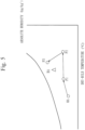
- Fig. 6 is a graph illustrating a relation between the latent heat load ⁇ X and a condensation temperature CT of the refrigerant in the heat exchanger 26.
- the horizontal axis represents the latent heat load ⁇ X
- the vertical axis represents the condensation temperature CT.
- the heating control unit 712 changes the condensation temperature CT of the refrigerant between a maximum value CTmax and a minimum value CTmin in accordance with the value of the latent heat load ⁇ X.
- the heating control unit 712 increases the condensation temperature CT as ⁇ X is larger.
- ⁇ X is larger, that is, as Xi is smaller with respect to X0
- the condensation temperature CT is higher.
- ⁇ X exceeds X1 the condensation temperature CT has the maximum value CTmax.
- ⁇ X is equal to or smaller than 0, that is, when Xi is equal to or larger than X0, the condensation temperature CT has the minimum value CTmin.
- a method of determining X1 in Fig. 6 is described.
- the value of X1 on the horizontal axis of Fig. 6 adopts, for example, a difference in absolute humidity corresponding to a relative humidity of 5%.
- a specific example is as follows. It is assumed that a target relative humidity at a temperature of 22°C is 50% and an absolute humidity of this target relative humidity is a (kg/kg'). It is assumed that an absolute humidity of a relative humidity of 45% at a temperature of 22°C is b (kg/kg'). A difference (a-b) in absolute humidity corresponding to a relative humidity of 5% is adopted as X1.
- [CTmax, CTmin] represents a set of the condensation temperature CTmax and the condensation temperature CTmin.
- [CTmax, CTmin] is retained by the heating control unit 712.
- One set of [CTmax, CTmin] may be retained, or the heating control unit 712 may retain [CTmax, CTmin] for each outside air condition.
- the outside air condition may be the outside air temperature or outside air humidity.
- CTmax and CTmin are higher as the outside air temperature decreases or the outside air humidity decreases.
- CTmax can be determined as follows. In a certain outside air humidity condition, when there are as many people in the interior 500 as a designed number of people who are present indoors, CTmax is determined as a condensation temperature which ensures a necessary latent heat load. On the other hand, CTmin can be determined as follows.
- CTmin is determined as a condensation temperature which ensures a necessary latent heat load.
- [CTmax, CTmin] is determined in accordance with the number of people who are present indoors.
- the heating control device 700 determines the condensation temperature CT of the refrigerant from the latent heat load ⁇ X and controls the compressor 22 so that the determined condensation temperature CT is achieved.
- the condensation temperature CT is decreased to allow the compressor 22 to be operated, and efficiency of a refrigerating cycle as the second refrigerant system 21 is improved.
- the condensation temperature CT of the refrigerant in the heat exchanger 26 is decreased to decrease the amount of heating by the heat exchanger 26, the point P2 in Fig. 5 is close to the point P1, and the blowout temperature Tsa of blowout air at the point P3 is decreased.
- the blowout temperature Tsa is decreased, there is a possibility that occupants feel chilly.
- the heating control unit 712 continues operation of the compressor 22 at the condensation temperature CT determined from the graph of Fig. 6 .
- the heating control unit 712 increases the condensation temperature CT by increasing the frequency of the compressor 22 when the blowout temperature Tsa detected by the heated outside air temperature sensor 502 is smaller than a threshold to control so that the blowout temperature Tsa is equal to or larger than the threshold TH.
- Fig. 7 illustrates the hardware structure of the heating control device 700. With reference to Fig. 7 , the hardware structure of the heating control device 700 is described.
- the heating control device 700 includes, as functional elements, the estimating unit 711 and the heating control unit 712.
- the functions of the estimating unit 711 and the heating control unit 712 are implemented by a heating control program 701.
- the processor 710 is a device which executes the heating control program 701.
- the heating control program 701 is a program which implements the functions of the estimating unit 711 and the heating control unit 712.
- the processor 710 is an IC (Integrated Circuit) which performs arithmetic process. Specific examples of the processor 710 are CPU (Centra Processing Unit), DSP (Digital Signal Processor), and GPU (Graphics Processing Unit).
- the main storage device 720 is a storage device. Specific examples of the main storage device 720 are SRAM (Static Random Access Memory) and DRAM (Dynamic Random Access Memory). The main storage device 720 retains the arithmetic results of the processor 710.
- the auxiliary storage device 730 is a storage device which stores data in a nonvolatile manner.
- the auxiliary storage device 730 has the heating control program 701 stored therein.
- a specific example of the auxiliary storage device 730 is HDD (Hard Disk Drive).
- the auxiliary storage device 730 may be a portable recording medium such as SD (registered trademark) (Secure Digital) memory card, NAND flash, flexible disc, optical disc, compact disc, Blu-ray (registered trademark) disc, or DVD (Digital Versatile Disk).
- the input IF 740 is a port to which data is inputted from each device.
- the input IF 740 To the input IF 740, the indoor humidity sensor 501, the heated outside air temperature sensor 502, the outside air humidity sensor 601, the outside air temperature sensor 602, and the condensation temperature sensor 26a are connected.
- the output IF 750 is a port from which data is outputted by the processor 710 to various devices.
- the compressor 22 of the second refrigerant system 21 is connected.
- the communication IF 760 is a communication port for the processor 710 to communicate with another device.
- the temperature/humidity setting device 520 To the communication IF 760, the temperature/humidity setting device 520 is connected. Also, the temperature/humidity setting device 520 is connected to the system control device.
- the processor 710 loads the heating control program 701 from the auxiliary storage device 730 into the main storage device 720, and reads and executes the heating control program 701 from the main storage device 720.
- the heating control device 700 may include a plurality of processors which replace the processor 710. The plurality of these processors share execution of the heating control program 701. As with the processor 710, each processor is a device which executes the heating control program 701. Data, information, signal values, and variable values to be used, processed, or outputted by the heating control program 701 are stored in the main storage device 720, the auxiliary storage device 730, or a register or cache memory in the processor 710.
- the heating control program 701 is a program which causes a computer to execute each process, each procedure, or each step when "unit" in each of the estimating unit 711 and the heating control unit 712 is read as “process”, "procedure”, or "step”.
- the heating control method is a method to be performed by the heating control device 700 as a computer executing the heating control program 701.
- the heating control program 701 may be provided as being stored in a computer-readable recording medium or may be provided as a program product.
- Fig. 8 is a flowchart for describing operation of the heating control device 700. With reference to Fig. 8 , the operation of the heating control device 700 is described. The operation procedure of the heating control device 700 corresponds to a heating control method. A program for implementing the operation of the heating control device 700 corresponds to a heating control program.
- Step S11 to step S14 represent operation of the estimating unit 711.
- the estimating unit 711 estimates a latent heat load of air present in a ventilation target space as a ventilation target.
- the ventilation target space as a ventilation target is a space of the interior 500.
- Step S15 to step S20 represent operation of the heating control unit 712.
- the heating control unit 712 controls a temperature of outside air by a heater, the outside air being supplied to the ventilation target space, in accordance with the latent heat load estimated by the estimating unit 711.
- the heater is the heat exchanger 26.
- the heat exchanger 26 as a heater is a condenser of the refrigerating cycle device where the refrigerant circulates, the refrigerating cycle device including the compressor 22, the heat exchanger 26 which functions as the condenser, the expansion valve 25 as an expansion mechanism, and the heat exchanger 24 which functions as an evaporator.
- the heating control unit 712 controls the condensation temperature of the refrigerant in the heat exchanger 26 as a condenser.
- the estimating unit 711 acquires, from the outside air temperature sensor 602, the outside air temperature detected by the outside air temperature sensor 602.
- the heating control unit 712 determines the first condensation temperature CTmin of the refrigerant and the second condensation temperature CTmax higher than the first condensation temperature CTmin, based on the outside air condition indicating at least either value of a detected temperature of outside air and a detected absolute humidity, which is an absolute humidity detected for outside air.
- the heating control unit 712 determines a condensation temperature CTi in a range between the first condensation temperature CTmin and the second condensation temperature CTmax.
- the first condensation temperature is CTmin described below
- the second condensation temperature is CTmax described below.
- the estimating unit 711 determines one [CTmax, CTmin] from among a plurality of [CTmax, CTmin], based on the acquired outside air temperature.
- the estimating unit 711 has the plurality of [CTmax, CTmin].
- Each [CTmax, CTmin] of the plurality of [CTmax, CTmin] is associated with an outside air temperature.
- [CTmax(1), CTmin(1)] is associated with a range of outside air temperatures equal to or higher than 18°C and lower than 20°C
- [CTmax(2), CTmin(2)] is associated with a range of outside air temperatures equal to or higher than 20°C and lower than 22°C.
- the estimating unit 711 can determine one [CTmax, CTmin] from the acquired outside air temperature.
- [CTmax, CTmin] may be determined from the outside air humidity detected by the outside air humidity sensor 601.
- CTmax, CTmin] are stored in the auxiliary storage device 730.
- the outside air condition includes a detected temperature of outside air, and the heating control unit 712 determines the first condensation temperature CTmin and the second condensation temperature CTmax at higher temperatures as the detected temperature of outside air is lower. Also, the outside air condition includes a detected humidity of outside air, and the heating control unit 712 determines the first condensation temperature CTmin and the second condensation temperature CTmax at higher temperatures as the detected humidity of outside air is lower.
- the estimating unit 711 estimates the latent heat load ⁇ X based on X0 as the target humidity set by the temperature/humidity setting device 520 as a setting device which sets a target humidity in the ventilation target space and the detected humidity in the ventilation target space detected by the indoor humidity sensor 501.
- the estimating unit 711 may acquire a target relative humidity from the temperature/humidity setting device 520 and may acquire the temperature of the interior 500 from the temperature sensor which detects the temperature of the interior 500. The estimating unit 711 may calculate the target absolute humidity X0 from the target relative humidity and the temperature of the interior 500. Similarly, in place of the absolute humidity Xi, the estimating unit 711 may acquire a relative humidity of the interior 500 from the humidity sensor which detects the relative humidity of the interior 500 and may acquire the temperature of the interior 500 from the temperature sensor which detects the temperature of the interior 500. The estimating unit 711 may calculate the absolute humidity Xi of the interior 500 from the relative humidity of the interior 500 and the temperature of the interior 500.
- the heating control unit 712 generates a graph of Fig. 6 from X1, CTmax, and CTmin, and determines the condensation temperature CTi corresponding to the ⁇ X calculated at step S14. Note that the heating control unit 712 is assumed to previously have the value of X1, the method of determining which has been described in the description of Fig. 6 . X1 is stored in the auxiliary storage device 730.
- the heating control unit 712 determines the condensation temperature CTi of the refrigerant from the value indicated by the latent heat load ⁇ X, and controls the operation frequency of the compressor 22 so that the condensation temperature of the refrigerant in the heat exchanger 26 as a condenser is closer to the determined condensation temperature CTi. Description is specifically made below.
- the heating control unit 712 controls the operation frequency of the compressor 22 so that the condensation temperature CT of the refrigerant in the heat exchanger 26 is the determined condensation temperature CTi.
- the heating control unit 712 acquires the condensation temperature of the refrigerant detected by the condensation temperature sensor 26a. With reference to the condensation temperature of the refrigerant detected by the condensation temperature sensor 26a, the heating control unit 712 controls the operation frequency of the compressor 22 so that the condensation temperature CT of the medium is the determined condensation temperature CTi.
- the heating control unit 712 When the determined condensation temperature CTi is higher than the current condensation temperature of the refrigerant detected by the condensation temperature sensor 26a, the heating control unit 712 performs control of increasing the operation frequency of the compressor 22. When the determined condensation temperature CTi is lower than the current condensation temperature of the refrigerant detected by the condensation temperature sensor 26a, the heating control unit 712 performs control of decreasing the operation frequency of the compressor 22.
- the heating control unit 712 acquires, from the heated outside air temperature sensor 502, the blowout temperature Tsa detected by the heated outside air temperature sensor 502.
- the heating control unit 712 determines whether the mode is the blowout-temperature priority mode.
- the heating control unit 712 has already acquired information about whether the mode is the blowout-temperature priority mode from the temperature/humidity setting device 520.
- the process returns to step S11.
- the process proceeds to step S19.
- the blowout-temperature priority mode is a mode in which the heating control unit 712 controls the blowout temperature Tsa so that the blowout temperature Tsa is equal to or larger than the threshold TH.
- the heating control unit 712 determines whether the blowout temperature Tsa is smaller than the threshold TH. When the blowout temperature Tsa is not smaller than the threshold TH, the process returns to step S11. When the blowout temperature Tsa is smaller than the threshold TH, the process proceeds to step S20.
- the heating control unit 712 controls the operation frequency of the compressor 22 so that the blowout temperature Tsa is equal to or larger than the threshold TH. Specific control is as follows.
- the heating control unit 712 has the threshold TH.
- the threshold TH is stored in the auxiliary storage device 730.
- the heating control unit 712 performs control of increasing the operation frequency of the compressor 22 when the blowout temperature Tsa, which is the temperature of heated outside air detected by the heated outside air temperature sensor 502 which detects the temperature of heated outside air, is smaller than the threshold TH.
- Heated outside air is outside air supplied to the interior 500 as a ventilation target space, and is outside air heated by the heat exchanger 26 as a heater.
- the heating control device 700 controls the condensation temperature of the refrigerant of the heat exchanger 26 in accordance with the latent heat load ⁇ X.
- the heating control device 700 decreases the condensation temperature CT of the refrigerant in the heat exchanger 26 to decrease the amount of heating outside air by the heat exchanger 26.
- efficiency of operation of the refrigerating cycle is enhanced, and energy can be saved.
- the heating control device 700 increases the condensation temperature CT of the refrigerant in the heat exchanger 26 to increase the amount of heating outside air by the heat exchanger 26. Thus, shortage of the amount of humidification of outside air can be avoided.
- the heating control unit 712 performs control in accordance with the blowout-temperature priority mode.
- comfortability in the interior 500 can also be maintained.
- the functions of the estimating unit 711 and the heating control unit 712 are implemented by software in the heating control device 700 of Fig. 7 , the functions of the heating control device 700 may be implemented by hardware.
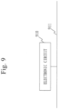
- Fig. 9 illustrates a structure in which the functions of the heating control device 700 are implemented by hardware.
- An electronic circuit 910 of Fig. 9 is a dedicated electronic circuit which implements the functions of the estimating unit 711 and the heating control unit 712 of the heating control device 700.
- the electronic circuit 910 is connected to a signal line 911.
- the electronic circuit 910 is, specifically, a single circuit, composite circuit, programmed processor, parallel-programmed processor, logic IC, GA, ASIC, or FPGA.
- GA is an abbreviation of Gate Array.
- ASIC is an abbreviation of Application Specific Integrated Circuit.
- FPGA is an abbreviation of Field-Programmable Gate Array.
- the functions of the components of the heating control device 700 may be implemented by one electronic circuit or may be implemented as being dispersed into a plurality of electronic circuits. Also, part of the functions of the components of the heating control device 700 may be implemented by an electronic circuit and the remaining functions may be implemented by software.
- Each of the processor 710 and the electronic circuit 910 is also referred to as processing circuitry.
- the functions of the estimating unit 711, the heating control unit 712, the main storage device 720, the auxiliary storage device 730, the input IF 740, the output IF 750, and the communication IF 760 may be implemented by processing circuitry.
- Tsa blowout temperature; TH: threshold; 100: air conditioning system; 11: first refrigerant system; 11a: indoor unit; 11b: outdoor unit; 11c: refrigerant pipe; 12: compressor; 13: four-way valve; 14: outdoor heat exchanger; 15: expansion valve; 16: indoor heat exchanger; 17: air blower; 18: air blower; 21: second refrigerant system; 21b: outdoor unit; 21c: refrigerant pipe; 22: compressor; 23: four-way valve; 24: heat exchanger; 25: expansion valve; 26: heat exchanger; 26a: condensation temperature sensor; 27: air blower; 28: air blower; 29: air blower; 30: system control device; 210: ventilation device; 211: exhaust pipe; 212: air supply pipe; 213: humidifying element; 214: total heat exchanger; 500: interior; 501: indoor humidity sensor; 502: heated outside air temperature sensor; 511: system control device; 520: temperature/humidity setting device; 601: outside air humidity sensor;
Landscapes
- Engineering & Computer Science (AREA)
- Mechanical Engineering (AREA)
- General Engineering & Computer Science (AREA)
- Physics & Mathematics (AREA)
- Thermal Sciences (AREA)
- Chemical & Material Sciences (AREA)
- Combustion & Propulsion (AREA)
- Air Conditioning Control Device (AREA)
- Central Air Conditioning (AREA)
Abstract
Description
- The present disclosure relates to a heating control device and heating control program for performing heating control of air humidified by a humidifying element.
- In a conventional air conditioning system, a ventilation device system and an indoor unit system each have a refrigerating cycle. A ventilation device of the ventilation device system performs operation of supplying outdoor fresh air to the interior. When enthalpy of air introduced from outside air is higher than enthalpy of indoor air, the load is a cooling load. In the case of the cooling load, outdoor air may be cooled by the ventilation device and introduced to the interior. On the other hand, when enthalpy of air introduced from outside air is lower than enthalpy of indoor air, the load is a heating load. In the case of the heating load, outdoor air may be heated by the ventilation device and introduced to the interior.
- The refrigerating cycle of the indoor unit system is configured of a compressor, a four-way valve, an outdoor heat exchanger, expansion means, and an indoor heat exchanger. The refrigerating cycle of the ventilation device system is configured of a compressor, a four-way valve, an outdoor heat exchanger, expansion means, and a heat exchanger for the ventilation device. The refrigerating cycles of the indoor unit system and the ventilation device system are filled with a refrigerant. At the time of cooling, the refrigerant compressed by the compressor becomes a gas refrigerant at high temperature and high pressure, and is sent to the outdoor heat exchanger. The refrigerant flowing into the outdoor heat exchanger is liquefied by emitting heat to air. The liquefied refrigerant is decompressed by the expansion means to become in a gas-liquid two phase state, and is gasified by absorbing heat from ambient air by the indoor heat exchanger or the heat exchanger for the ventilation device. On the other hand, air is deprived of heat and thus becomes cooled air to cool an indoor space. The gasified refrigerant returns to the compressor.
- At the time of heating, the refrigerant compressed by the compressor becomes a gas refrigerant at high temperature and high pressure, and is sent to the indoor heat exchanger or the heat exchanger for the ventilation device. The refrigerant flowing into the indoor heat exchanger or the heat exchanger for the ventilation device is liquefied by emitting heat to air. On the other hand, air is provided with heat and thus becomes heated air. The liquefied refrigerant is decompressed by the expansion means to become a gas-liquid two phase state, and is gasified by absorbing heat from ambient air by the outdoor heat exchanger. The gasified refrigerant returns to the compressor. Air heated by the indoor heat exchanger is supplied as it is to an air conditioning space to heat the space. Air heated by the heat exchanger for the ventilation device passes through a humidifying element installed on a leeward side to become humidified air, which is supplied to the air conditioning space to humidify the space.
- As prior art, there is a technique of adjusting the amount of heating in a heat exchanger for a ventilation device in accordance with the temperature of indoor air so that the indoor temperature is not excessively increased and adjusting bypass air quantity inside the ventilation device in accordance with indoor humidity (for example, Patent Literature 1).
- Patent Literature 1:
WO 2019/008694 pamphlet - In conventional technologies, heating control is not performed on outside air flowing into the ventilation device based on the degree of the latent heat load of air in the air conditioning space. Thus, even if the latent heat load is small and the amount of heating is not required to be large, outside air is heated by the heat exchanger for the ventilation device with a larger amount of heating than a necessary amount of heating, and energy losses are produced.
- The present disclosure is to provide a heating control device which performs heating control on outside air flowing into a ventilation device in accordance with the latent heat load of air in an air conditioning space.
- A heating control device according to the present invention includes:
- an estimating unit to estimate a latent heat load of air present in a ventilation target space as a ventilation target; and
- a heating control unit to control a temperature of outside air heated by a heater, the outside air being supplied to the ventilation target space, in accordance with the estimated latent heat load.
- Since the heating control device of the present disclosure includes the estimating unit and the heating control unit, heating control can be performed on outside air flowing into the ventilation device in accordance with the latent heat load of air in the air conditioning space. Thus, according to the heating control device of the present disclosure, energy saving can be achieved when outside air is heated by the heat exchanger for the ventilation device.
-
-
Fig. 1 is a drawing ofEmbodiment 1 and is a schematic diagram of anair conditioning system 100. -
Fig. 2 is a drawing ofEmbodiment 1 and is a schematic diagram of afirst refrigerant system 11. -
Fig. 3 is a drawing ofEmbodiment 1 and is a schematic diagram of asecond refrigerant system 21. -
Fig. 4 is a drawing ofEmbodiment 1, illustrating aventilation device 210. -
Fig. 5 is a drawing ofEmbodiment 1, illustrating a psychrometric chart. -
Fig. 6 is a drawing ofEmbodiment 1, illustrating a relation between ΔX and a condensation temperature CT of a refrigerant. -
Fig. 7 is a drawing ofEmbodiment 1, illustrating the hardware structure of aheating control device 700. -
Fig. 8 is a drawing ofEmbodiment 1 and is a flowchart illustrating the operation of theheating control device 700. -
Fig. 9 is a drawing ofEmbodiment 1 and is a drawing of supplementing the hardware structure of theheating control device 700. - An embodiment is described below by using the drawings. Note that identical or corresponding portions in the respective drawings are provided with the same reference characters. In the description of the embodiment, description of identical or corresponding portions is omitted or simplified as appropriate.
-
Fig. 1 is a schematic diagram of anair conditioning system 100 ofEmbodiment 1.Fig. 1 is a schematic plan view of aninterior 500. Theair conditioning system 100 includes afirst refrigerant system 11, asecond refrigerant system 21, a system control device 30, and aheating control device 700. Thefirst refrigerant system 11 and thesecond refrigerant system 21 are refrigerating cycles. In aninterior 500, anindoor unit 11a of thefirst refrigerant system 11 and aventilation device 210 of thesecond refrigerant system 21 are arranged. Outside theinterior 500, anoutdoor unit 11b of thefirst refrigerant system 11 and anoutdoor unit 21b of thesecond refrigerant system 21 are arranged. The system control device 30 controls thefirst refrigerant system 11 and thesecond refrigerant system 21. -
Fig. 2 is a schematic diagram of thefirst refrigerant system 11. Arrows inFig. 2 indicate directions in which a refrigerant flows.Fig. 2 illustrates the structure of thefirst refrigerant system 11. Thefirst refrigerant system 11 includes acompressor 12, a four-way valve 13, anoutdoor heat exchanger 14, anexpansion valve 15, anindoor heat exchanger 16, anair blower 17 for the outdoor heat exchanger, and anair blower 18 for the indoor heat exchanger. Theindoor unit 11a is configured of theexpansion valve 15, theindoor heat exchanger 16, and theair blower 18. One or a plurality ofindoor units 11a are installed. -
Fig. 3 is a schematic diagram of thesecond refrigerant system 21. Arrows inFig. 3 indicate directions in which the refrigerant flows. Thesecond refrigerant system 21 includes acompressor 22, a four-way valve 23, anoutdoor heat exchanger 24, anexpansion valve 25, aheat exchanger 26 for use in theventilation device 210, anair blower 27 for use in theoutdoor heat exchanger 24, and anair blower 28 for ventilation. Theheat exchanger 26 and theair blower 28 are arranged inside theventilation device 210. Theheat exchanger 26 has arranged therein acondensation temperature sensor 26a which detects a condensation temperature of the refrigerant in theheat exchanger 26. -
Fig. 4 illustrates theventilation device 210. Theventilation device 210 includes aheat exchanger 26 of thesecond refrigerant system 21, theair blower 28 of thesecond refrigerant system 21, anair blower 29 for ventilation, ahumidifying element 213, and atotal heat exchanger 214. By thetotal heat exchanger 214, return air and outside air exchange total heat. By thehumidifying element 213, outside air is humidified. As illustrated inFig. 4 , theventilation device 210 has anexhaust pipe 211 which exhausts return air of the interior 500 as exhaust air and anair supply pipe 212 which supplies outside air as supply air to theinterior 500. InFig. 4 , return air, exhaust air, outside air, and supply air are denoted as RA, EA, OA, and SA, respectively. In theventilation device 210, return air is suctioned by theair blower 29 into theexhaust pipe 211. Return air exchanges total heat with outside air at thetotal heat exchanger 214, and passes through thetotal heat exchanger 214 to be exhausted as exhaust air. Outside air is suctioned by theair blower 28 into theair supply pipe 212. Outside air exchanges total heat with return air at thetotal heat exchanger 214, and passes through thetotal heat exchanger 214, theheat exchanger 26, and thehumidifying element 213 to be supplied as supply air to theinterior 500. Outside air is heated at theheat exchanger 26 and humidified when passing through thehumidifying element 213 to be supplied to theinterior 500. - As illustrated in
Fig. 1 , theair conditioning system 100 includes a temperature/humidity setting device 520 which accepts setting of a target temperature of the interior 500 and a target humidity of the interior 500 and aheating control device 700 which estimates a latent heat load and controls the condensation temperature of the refrigerant in theheat exchanger 26 based on the estimation result. The temperature/humidity setting device 520 is connected to theheating control device 700. Also, theair conditioning system 100 includes anindoor humidity sensor 501, a heated outsideair temperature sensor 502, an outsideair humidity sensor 601, an outsideair temperature sensor 602, and acondensation temperature sensor 26a. Theindoor humidity sensor 501 detects an indoor humidity. The heated outsideair temperature sensor 502 detects a blowout temperature Tsa of supply air blown out from theair supply pipe 212. The outsideair humidity sensor 601 detects a humidity of outside air. The outsideair temperature sensor 602 detects a temperature of outside air. Thecondensation temperature sensor 26a detects a condensation temperature of the refrigerant in theheat exchanger 26. Theindoor humidity sensor 501, the heated outsideair temperature sensor 502, the outsideair humidity sensor 601, the outsideair temperature sensor 602, and thecondensation temperature sensor 26a are connected to theheating control device 700. -
Fig. 5 is a psychrometric chart. P1, P2, and P3 illustrated in the psychrometric chart ofFig. 5 correspond to air states at positions P1, P2, and P3 ofFig. 4 . P1 inFig. 4 is a position of outside air immediately after passing through thetotal heat exchanger 214, P2 is a position of outside air immediately after passing through theheat exchanger 26, and P3 is a position of outside air immediately after passing through thehumidifying element 213. With reference toFig. 5 , changes of air inside theventilation device 210 are described. Theventilation device 210 takes outside air by theair blower 28 into the inside of theventilation device 210. Theair blower 29 takes return air of the interior 500 into the inside of theventilation device 210. Outside air exchanges total heat with return air at thetotal heat exchanger 214, thereby becoming in a state in which the temperature and the humidity both increase. This state arises at P1 inFig. 4 andFig. 5 . Thereafter, outside air is heated at theheat exchanger 26. This state arises at P2 inFig. 4 andFig. 5 . Outside air heated at theheat exchanger 26 passes through thehumidifying element 213 to be humidified by thehumidifying element 213 to become humidity-increased, temperature-decreased humidified air, and is supplied as supply air to theinterior 500. The state of outside air passing through thehumidifying element 213 arises at P3 inFig. 4 andFig. 5 . - Regarding outside air heated at the
heat exchanger 26, that is, outside air at P2 inFig. 5 , as a difference of a difference ΔTdw between a dry-bulb temperature and a wet-bulb temperature is larger, the amount of humidifying outside air by thehumidifying element 213 is larger. When the amount of heating by theheat exchanger 26 is large, the point P2 inFig. 5 moves to a right direction on the psychrometric chart to increase ΔTdw, and the amount of humidifying outside air by thehumidifying element 213 increases. By contrast, when the amount of heating by theheat exchanger 26 is small, the point P2 inFig. 5 does not move so much from the point P1 to the right direction to decrease ΔTdw, and the amount of humidifying outside air by thehumidifying element 213 decreases. That is, by adjusting the point P2 by the amount of heating at theheat exchanger 26, the amount of humidifying outside air by thehumidifying element 213 can be adjusted. - A method of adjusting the amount of humidifying outside air by the
humidifying element 213 is described. The amount of humidifying outside air by thehumidifying element 213 is required to be adjusted so as to be equal to a latent heat load. Here, the latent heat load is a humidifying load with respect to air of theinterior 500. Alternatively, the latent heat load is the amount of humidification required to maintain the humidity of the interior 500 at a target value. That is, the followingexpression 1 holds.
- An
estimating unit 711 described below estimates a latent heat load for achieving a target absolute humidity X0 of the interior 500 set by the temperature/humidity setting device 520. Aheating control unit 712 described below controls the condensation temperature of the refrigerant in theheat exchanger 26 in accordance with the latent heat load estimated by the estimatingunit 711. In theheating control device 700, the latent heat load, that is, the amount of humidification for achieving the target absolute humidity X0 of the interior 500, is estimated by the following expression 2. The estimatingunit 711 estimates a difference ΔX between the target absolute humidity X0 and an absolute humidity Xi of the current interior detected by theindoor humidity sensor 501 as a latent heat load.
That is,
- X0: Target absolute humidity set by the temperature/
humidity setting device 520 - Xi: Current absolute humidity of the interior 500
- In the following, the latent heat load is described as ΔX based on
expression 1. In the following, the latent heat load may be denoted as a latent heat load ΔX. -
Fig. 6 is a graph illustrating a relation between the latent heat load ΔX and a condensation temperature CT of the refrigerant in theheat exchanger 26. The horizontal axis represents the latent heat load ΔX, and the vertical axis represents the condensation temperature CT. Theheating control unit 712 changes the condensation temperature CT of the refrigerant between a maximum value CTmax and a minimum value CTmin in accordance with the value of the latent heat load ΔX. By following the graph ofFig. 6 , theheating control unit 712 increases the condensation temperature CT as ΔX is larger. As ΔX is larger, that is, as Xi is smaller with respect to X0, the condensation temperature CT is higher. When ΔX exceeds X1, the condensation temperature CT has the maximum value CTmax. When ΔX is equal to or smaller than 0, that is, when Xi is equal to or larger than X0, the condensation temperature CT has the minimum value CTmin. - A method of determining X1 in
Fig. 6 is described. The value of X1 on the horizontal axis ofFig. 6 adopts, for example, a difference in absolute humidity corresponding to a relative humidity of 5%. A specific example is as follows. It is assumed that a target relative humidity at a temperature of 22°C is 50% and an absolute humidity of this target relative humidity is a (kg/kg'). It is assumed that an absolute humidity of a relative humidity of 45% at a temperature of 22°C is b (kg/kg'). A difference (a-b) in absolute humidity corresponding to a relative humidity of 5% is adopted as X1. - A method of determining the condensation temperature CTmax and the condensation temperature CTmin in
Fig. 6 is described. [CTmax, CTmin] represents a set of the condensation temperature CTmax and the condensation temperature CTmin. [CTmax, CTmin] is retained by theheating control unit 712. One set of [CTmax, CTmin] may be retained, or theheating control unit 712 may retain [CTmax, CTmin] for each outside air condition. As the outside air temperature decreases, the absolute humidity of outside air decreases. Thus, the outside air condition may be the outside air temperature or outside air humidity. Thus, it is preferable that CTmax and CTmin are higher as the outside air temperature decreases or the outside air humidity decreases. - In the following example, the outside air condition is assumed to be the outside air temperature. Regarding an outside air temperature T1 and an outside air temperature T2, the outside air temperature T2 is assumed to be higher than the outside air temperature T1.
That is, it is assumed that

at the outside air temperature T2,


- In the above-described [CTmax, CTmin] determination method, the [CTmax, CTmin] determination method when the outside air condition is varied is described. In the following, a method is described in which CTmax and CTmin are determined in consideration of the number of people who are present in the
interior 500. First, CTmax can be determined as follows. In a certain outside air humidity condition, when there are as many people in the interior 500 as a designed number of people who are present indoors, CTmax is determined as a condensation temperature which ensures a necessary latent heat load. On the other hand, CTmin can be determined as follows. In a certain outside air humidity condition, when there are a few number of people, for example, when no one is present in the interior 500, CTmin is determined as a condensation temperature which ensures a necessary latent heat load. In this manner, [CTmax, CTmin] is determined in accordance with the number of people who are present indoors. With this method of determining the condensation temperature CTmax and the condensation temperature CTmin, a range in which shortage of humidification or excessive humidification does not occur can be determined for each outside air condition. Thus, comfortability and energy-saving can be ensured. - As illustrated in
Fig. 6 , theheating control device 700 determines the condensation temperature CT of the refrigerant from the latent heat load ΔX and controls thecompressor 22 so that the determined condensation temperature CT is achieved. Thus, when the latent heat load ΔX is small, the condensation temperature CT is decreased to allow thecompressor 22 to be operated, and efficiency of a refrigerating cycle as thesecond refrigerant system 21 is improved. However, if the condensation temperature CT of the refrigerant in theheat exchanger 26 is decreased to decrease the amount of heating by theheat exchanger 26, the point P2 inFig. 5 is close to the point P1, and the blowout temperature Tsa of blowout air at the point P3 is decreased. When the blowout temperature Tsa is decreased, there is a possibility that occupants feel chilly. - Thus, the
heating control unit 712 has an energy-saving priority mode and a blowout-temperature priority mode, and changes control operation depending on which mode the user selects. The temperature/humidity setting device 520 has a mode selection function of allowing the user to select either of the energy-saving priority mode and the blowout-temperature priority mode. When the user selects either mode by using the temperature/humidity setting device 520, theheating control unit 712 detects the selected mode. - When the energy-saving priority mode is selected, the
heating control unit 712 continues operation of thecompressor 22 at the condensation temperature CT determined from the graph ofFig. 6 . When the blowout-temperature priority mode is selected, theheating control unit 712 increases the condensation temperature CT by increasing the frequency of thecompressor 22 when the blowout temperature Tsa detected by the heated outsideair temperature sensor 502 is smaller than a threshold to control so that the blowout temperature Tsa is equal to or larger than the threshold TH. The energy-saving priority mode and the blowout-temperature priority mode will be described further below in description of operation. -
Fig. 7 illustrates the hardware structure of theheating control device 700. With reference toFig. 7 , the hardware structure of theheating control device 700 is described. - The
heating control device 700 is a computer. Theheating control device 700 includes aprocessor 710. Theheating control device 700 includes, in addition to theprocessor 710, other pieces of hardware such as amain storage device 720, anauxiliary storage device 730, an input IF 740, an output IF 750, and a communication IF 760. Theprocessor 710 is connected to the other pieces of hardware via asignal line 770 to control the other hardware. - The
heating control device 700 includes, as functional elements, the estimatingunit 711 and theheating control unit 712. The functions of theestimating unit 711 and theheating control unit 712 are implemented by aheating control program 701. - The
processor 710 is a device which executes theheating control program 701. Theheating control program 701 is a program which implements the functions of theestimating unit 711 and theheating control unit 712. Theprocessor 710 is an IC (Integrated Circuit) which performs arithmetic process. Specific examples of theprocessor 710 are CPU (Centra Processing Unit), DSP (Digital Signal Processor), and GPU (Graphics Processing Unit). - The
main storage device 720 is a storage device. Specific examples of themain storage device 720 are SRAM (Static Random Access Memory) and DRAM (Dynamic Random Access Memory). Themain storage device 720 retains the arithmetic results of theprocessor 710. - The
auxiliary storage device 730 is a storage device which stores data in a nonvolatile manner. Theauxiliary storage device 730 has theheating control program 701 stored therein. A specific example of theauxiliary storage device 730 is HDD (Hard Disk Drive). Also, theauxiliary storage device 730 may be a portable recording medium such as SD (registered trademark) (Secure Digital) memory card, NAND flash, flexible disc, optical disc, compact disc, Blu-ray (registered trademark) disc, or DVD (Digital Versatile Disk). - The input IF 740 is a port to which data is inputted from each device. To the input IF 740, the
indoor humidity sensor 501, the heated outsideair temperature sensor 502, the outsideair humidity sensor 601, the outsideair temperature sensor 602, and thecondensation temperature sensor 26a are connected. The output IF 750 is a port from which data is outputted by theprocessor 710 to various devices. To the output IF 750, thecompressor 22 of thesecond refrigerant system 21 is connected. The communication IF 760 is a communication port for theprocessor 710 to communicate with another device. To the communication IF 760, the temperature/humidity setting device 520 is connected. Also, the temperature/humidity setting device 520 is connected to the system control device. - The
processor 710 loads theheating control program 701 from theauxiliary storage device 730 into themain storage device 720, and reads and executes theheating control program 701 from themain storage device 720. Theheating control device 700 may include a plurality of processors which replace theprocessor 710. The plurality of these processors share execution of theheating control program 701. As with theprocessor 710, each processor is a device which executes theheating control program 701. Data, information, signal values, and variable values to be used, processed, or outputted by theheating control program 701 are stored in themain storage device 720, theauxiliary storage device 730, or a register or cache memory in theprocessor 710. - The
heating control program 701 is a program which causes a computer to execute each process, each procedure, or each step when "unit" in each of theestimating unit 711 and theheating control unit 712 is read as "process", "procedure", or "step". - Also, the heating control method is a method to be performed by the
heating control device 700 as a computer executing theheating control program 701. Theheating control program 701 may be provided as being stored in a computer-readable recording medium or may be provided as a program product. -
Fig. 8 is a flowchart for describing operation of theheating control device 700. With reference toFig. 8 , the operation of theheating control device 700 is described. The operation procedure of theheating control device 700 corresponds to a heating control method. A program for implementing the operation of theheating control device 700 corresponds to a heating control program. - Step S11 to step S14 represent operation of the
estimating unit 711. The estimatingunit 711 estimates a latent heat load of air present in a ventilation target space as a ventilation target. The ventilation target space as a ventilation target is a space of theinterior 500. Step S15 to step S20 represent operation of theheating control unit 712. Theheating control unit 712 controls a temperature of outside air by a heater, the outside air being supplied to the ventilation target space, in accordance with the latent heat load estimated by the estimatingunit 711. The heater is theheat exchanger 26. Theheat exchanger 26 as a heater is a condenser of the refrigerating cycle device where the refrigerant circulates, the refrigerating cycle device including thecompressor 22, theheat exchanger 26 which functions as the condenser, theexpansion valve 25 as an expansion mechanism, and theheat exchanger 24 which functions as an evaporator. As control of the temperature of the outside air, theheating control unit 712 controls the condensation temperature of the refrigerant in theheat exchanger 26 as a condenser. - After the start of operation of the
air conditioning system 100, at step S11, the estimatingunit 711 acquires, from the outsideair temperature sensor 602, the outside air temperature detected by the outsideair temperature sensor 602. - At step S12, the
heating control unit 712 determines the first condensation temperature CTmin of the refrigerant and the second condensation temperature CTmax higher than the first condensation temperature CTmin, based on the outside air condition indicating at least either value of a detected temperature of outside air and a detected absolute humidity, which is an absolute humidity detected for outside air. Theheating control unit 712 determines a condensation temperature CTi in a range between the first condensation temperature CTmin and the second condensation temperature CTmax. The first condensation temperature is CTmin described below, and the second condensation temperature is CTmax described below. - A specific process is as follows. The estimating
unit 711 determines one [CTmax, CTmin] from among a plurality of [CTmax, CTmin], based on the acquired outside air temperature. The estimatingunit 711 has the plurality of [CTmax, CTmin]. Each [CTmax, CTmin] of the plurality of [CTmax, CTmin] is associated with an outside air temperature. For example, [CTmax(1), CTmin(1)] is associated with a range of outside air temperatures equal to or higher than 18°C and lower than 20°C, and [CTmax(2), CTmin(2)] is associated with a range of outside air temperatures equal to or higher than 20°C and lower than 22°C. Thus, the estimatingunit 711 can determine one [CTmax, CTmin] from the acquired outside air temperature. Note that when a plurality of [CTmax, CTmin] are associated with an outside air humidity, [CTmax, CTmin] may be determined from the outside air humidity detected by the outsideair humidity sensor 601. - [CTmax, CTmin] are stored in the
auxiliary storage device 730. - As described above, the outside air condition includes a detected temperature of outside air, and the
heating control unit 712 determines the first condensation temperature CTmin and the second condensation temperature CTmax at higher temperatures as the detected temperature of outside air is lower. Also, the outside air condition includes a detected humidity of outside air, and theheating control unit 712 determines the first condensation temperature CTmin and the second condensation temperature CTmax at higher temperatures as the detected humidity of outside air is lower. - At step S13, the estimating
unit 711 acquires the current absolute humidity Xi of the interior 500 from theindoor humidity sensor 501. Also, the estimatingunit 711 acquires the target absolute humidity X0 of the interior 500 set by the temperature/humidity setting device 520. - In this manner,
- At step S14, the estimating
unit 711 calculates the difference ΔX between the target absolute humidity X0 and the absolute humidity Xi of theinterior 500. The estimatingunit 711 calculates X0-Xi = ΔX. - The estimating
unit 711 estimates the latent heat load ΔX based on X0 as the target humidity set by the temperature/humidity setting device 520 as a setting device which sets a target humidity in the ventilation target space and the detected humidity in the ventilation target space detected by theindoor humidity sensor 501. - Note that in place of the target absolute humidity X0, the estimating
unit 711 may acquire a target relative humidity from the temperature/humidity setting device 520 and may acquire the temperature of the interior 500 from the temperature sensor which detects the temperature of theinterior 500. The estimatingunit 711 may calculate the target absolute humidity X0 from the target relative humidity and the temperature of theinterior 500. Similarly, in place of the absolute humidity Xi, the estimatingunit 711 may acquire a relative humidity of the interior 500 from the humidity sensor which detects the relative humidity of the interior 500 and may acquire the temperature of the interior 500 from the temperature sensor which detects the temperature of theinterior 500. The estimatingunit 711 may calculate the absolute humidity Xi of the interior 500 from the relative humidity of the interior 500 and the temperature of theinterior 500. - At step S15, the
heating control unit 712 generates a graph ofFig. 6 from X1, CTmax, and CTmin, and determines the condensation temperature CTi corresponding to the ΔX calculated at step S14. Note that theheating control unit 712 is assumed to previously have the value of X1, the method of determining which has been described in the description ofFig. 6 . X1 is stored in theauxiliary storage device 730. - At step S16, the
heating control unit 712 determines the condensation temperature CTi of the refrigerant from the value indicated by the latent heat load ΔX, and controls the operation frequency of thecompressor 22 so that the condensation temperature of the refrigerant in theheat exchanger 26 as a condenser is closer to the determined condensation temperature CTi. Description is specifically made below. Theheating control unit 712 controls the operation frequency of thecompressor 22 so that the condensation temperature CT of the refrigerant in theheat exchanger 26 is the determined condensation temperature CTi. Theheating control unit 712 acquires the condensation temperature of the refrigerant detected by thecondensation temperature sensor 26a. With reference to the condensation temperature of the refrigerant detected by thecondensation temperature sensor 26a, theheating control unit 712 controls the operation frequency of thecompressor 22 so that the condensation temperature CT of the medium is the determined condensation temperature CTi. - When the determined condensation temperature CTi is higher than the current condensation temperature of the refrigerant detected by the
condensation temperature sensor 26a, theheating control unit 712 performs control of increasing the operation frequency of thecompressor 22. When the determined condensation temperature CTi is lower than the current condensation temperature of the refrigerant detected by thecondensation temperature sensor 26a, theheating control unit 712 performs control of decreasing the operation frequency of thecompressor 22. - At step S17, the
heating control unit 712 acquires, from the heated outsideair temperature sensor 502, the blowout temperature Tsa detected by the heated outsideair temperature sensor 502. - At step S18, the
heating control unit 712 determines whether the mode is the blowout-temperature priority mode. Theheating control unit 712 has already acquired information about whether the mode is the blowout-temperature priority mode from the temperature/humidity setting device 520. When the mode is not the blowout-temperature priority mode, the process returns to step S11. When the mode is the blowout-temperature priority mode, the process proceeds to step S19. The blowout-temperature priority mode is a mode in which theheating control unit 712 controls the blowout temperature Tsa so that the blowout temperature Tsa is equal to or larger than the threshold TH. - At step S19, the
heating control unit 712 determines whether the blowout temperature Tsa is smaller than the threshold TH. When the blowout temperature Tsa is not smaller than the threshold TH, the process returns to step S11. When the blowout temperature Tsa is smaller than the threshold TH, the process proceeds to step S20. - At step S20, the
heating control unit 712 controls the operation frequency of thecompressor 22 so that the blowout temperature Tsa is equal to or larger than the threshold TH. Specific control is as follows. - The
heating control unit 712 has the threshold TH. The threshold TH is stored in theauxiliary storage device 730. Theheating control unit 712 performs control of increasing the operation frequency of thecompressor 22 when the blowout temperature Tsa, which is the temperature of heated outside air detected by the heated outsideair temperature sensor 502 which detects the temperature of heated outside air, is smaller than the threshold TH. Heated outside air is outside air supplied to the interior 500 as a ventilation target space, and is outside air heated by theheat exchanger 26 as a heater. - The
heating control device 700 controls the condensation temperature of the refrigerant of theheat exchanger 26 in accordance with the latent heat load ΔX. When the latent heat load ΔX is low, theheating control device 700 decreases the condensation temperature CT of the refrigerant in theheat exchanger 26 to decrease the amount of heating outside air by theheat exchanger 26. Thus, efficiency of operation of the refrigerating cycle is enhanced, and energy can be saved. Also, when the latent heat load ΔX is high, theheating control device 700 increases the condensation temperature CT of the refrigerant in theheat exchanger 26 to increase the amount of heating outside air by theheat exchanger 26. Thus, shortage of the amount of humidification of outside air can be avoided. - Also, as illustrated at step S20 of
Fig. 8 , theheating control unit 712 performs control in accordance with the blowout-temperature priority mode. Thus, comfortability in the interior 500 can also be maintained. - While the functions of the
estimating unit 711 and theheating control unit 712 are implemented by software in theheating control device 700 ofFig. 7 , the functions of theheating control device 700 may be implemented by hardware. -
Fig. 9 illustrates a structure in which the functions of theheating control device 700 are implemented by hardware. Anelectronic circuit 910 ofFig. 9 is a dedicated electronic circuit which implements the functions of theestimating unit 711 and theheating control unit 712 of theheating control device 700. Theelectronic circuit 910 is connected to asignal line 911. Theelectronic circuit 910 is, specifically, a single circuit, composite circuit, programmed processor, parallel-programmed processor, logic IC, GA, ASIC, or FPGA. GA is an abbreviation of Gate Array. ASIC is an abbreviation of Application Specific Integrated Circuit. FPGA is an abbreviation of Field-Programmable Gate Array. The functions of the components of theheating control device 700 may be implemented by one electronic circuit or may be implemented as being dispersed into a plurality of electronic circuits. Also, part of the functions of the components of theheating control device 700 may be implemented by an electronic circuit and the remaining functions may be implemented by software. - Each of the
processor 710 and theelectronic circuit 910 is also referred to as processing circuitry. In theheating control device 700, the functions of theestimating unit 711, theheating control unit 712, themain storage device 720, theauxiliary storage device 730, the input IF 740, the output IF 750, and the communication IF 760 may be implemented by processing circuitry. - Tsa: blowout temperature; TH: threshold; 100: air conditioning system; 11: first refrigerant system; 11a: indoor unit; 11b: outdoor unit; 11c: refrigerant pipe; 12: compressor; 13: four-way valve; 14: outdoor heat exchanger; 15: expansion valve; 16: indoor heat exchanger; 17: air blower; 18: air blower; 21: second refrigerant system; 21b: outdoor unit; 21c: refrigerant pipe; 22: compressor; 23: four-way valve; 24: heat exchanger; 25: expansion valve; 26: heat exchanger; 26a: condensation temperature sensor; 27: air blower; 28: air blower; 29: air blower; 30: system control device; 210: ventilation device; 211: exhaust pipe; 212: air supply pipe; 213: humidifying element; 214: total heat exchanger; 500: interior; 501: indoor humidity sensor; 502: heated outside air temperature sensor; 511: system control device; 520: temperature/humidity setting device; 601: outside air humidity sensor; 602: outside air temperature sensor; 700: heating control device; 701: heating control program; 710: processor; 711: estimating unit; 712: heating control unit; 720: main storage device; 730: auxiliary storage device; 740: input IF; 750: output IF; 760: communication IF; 770: signal line; 910: electronic circuit; 911: signal line
Claims (10)
- A heating control device comprising:an estimating unit to estimate a latent heat load of air present in a ventilation target space as a ventilation target; anda heating control unit to control a temperature of outside air heated by a heater, the outside air being supplied to the ventilation target space, in accordance with the estimated latent heat load.
- The heating control device according to claim 1, whereinthe heater is a condenser of a refrigerating cycle device where a refrigerant circulates, the refrigerating cycle device including a compressor, the condenser, an expansion mechanism, and an evaporator; andthe heating control unit controls a condensation temperature of the refrigerant in the condenser as control of the temperature of the outside air.
- The heating control device according to claim 2, wherein
the heating control unit determines the condensation temperature of the refrigerant from a value indicated by the latent heat load, and controls an operation frequency of the compressor so that the condensation temperature of the refrigerant in the condenser is closer to the determined condensation temperature. - The heating control device according to claim 3, wherein
the heating control unit performs control of increasing the operation frequency of the compressor when the determined condensation temperature is higher than a current said condensation temperature of the refrigerant, and performs control of decreasing the operation frequency of the compressor when the determined condensation temperature is lower than the current condensation temperature of the refrigerant. - The heating control device according to claim 3 or 4, wherein
the heating control unit has a threshold, and performs control of increasing the operation frequency of the compressor when a temperature of heated outside air, which is the outside air supplied to the ventilation target space and heated by the heater, detected by a heated outside air temperature sensor to detect the temperature of the heated outside air is smaller than the threshold. - The heating control device according to any one of claims 3 to 5, wherein
the heating control unit determines a first condensation temperature of the refrigerant and a second condensation temperature higher than the first condensation temperature, based on an outside air condition indicating at least either value of a detected temperature of the outside air and a detected absolute humidity, which is an absolute humidity detected for the outside air, and determines the condensation temperature in a range between the first condensation temperature and the second condensation temperature. - The heating control device according to claim 6, whereinthe outside air condition includes the detected temperature of the outside air, andthe heating control unit determines the first condensation temperature and the second condensation temperature at higher temperatures as the detected temperature of the outside air is lower.
- The heating control device according to claim 6, whereinthe outside air condition includes a detected humidity of the outside air, andthe heating control unit determines the first condensation temperature and the second condensation temperature at higher temperatures as the detected humidity of the outside air is lower.
- The heating control device according to any one of claims 1 to 8, wherein
the estimating unit estimates the latent heat load based on a target humidity set by a setting device to set the target humidity in the ventilation target space and a detected humidity in the ventilation target space detected by a humidity sensor. - A heating control program that causes a computer to execute:an estimation process of estimating a latent heat load of air present in a ventilation target space as a ventilation target; anda heating control process of controlling a temperature of outside air being heated by a heater, the outside air being supplied to the ventilation target space, in accordance with the estimated latent heat load.
Applications Claiming Priority (1)
| Application Number | Priority Date | Filing Date | Title |
|---|---|---|---|
| PCT/JP2020/018993 WO2021229687A1 (en) | 2020-05-12 | 2020-05-12 | Heating control device and heating control program |
Publications (2)
| Publication Number | Publication Date |
|---|---|
| EP4151915A1 true EP4151915A1 (en) | 2023-03-22 |
| EP4151915A4 EP4151915A4 (en) | 2023-06-21 |
Family
ID=78526010
Family Applications (1)
| Application Number | Title | Priority Date | Filing Date |
|---|---|---|---|
| EP20935466.1A Withdrawn EP4151915A4 (en) | 2020-05-12 | 2020-05-12 | HEATING CONTROL DEVICE AND HEATING CONTROL PROGRAM |
Country Status (5)
| Country | Link |
|---|---|
| US (1) | US20230101146A1 (en) |
| EP (1) | EP4151915A4 (en) |
| JP (1) | JP7305043B2 (en) |
| CN (1) | CN115552180A (en) |
| WO (1) | WO2021229687A1 (en) |
Families Citing this family (1)
| Publication number | Priority date | Publication date | Assignee | Title |
|---|---|---|---|---|
| KR102934117B1 (en) * | 2020-07-13 | 2026-03-09 | 삼성전자주식회사 | air conditioner and controlling method thereof |
Family Cites Families (19)
| Publication number | Priority date | Publication date | Assignee | Title |
|---|---|---|---|---|
| JP2002018228A (en) * | 2000-07-07 | 2002-01-22 | Daikin Ind Ltd | Humidity control device |
| JP3555590B2 (en) | 2001-04-18 | 2004-08-18 | ダイキン工業株式会社 | Humidity control device |
| US7886556B2 (en) * | 2004-03-31 | 2011-02-15 | Daikin Industries, Ltd. | Air conditioning system |
| JP3712000B2 (en) * | 2004-03-31 | 2005-11-02 | ダイキン工業株式会社 | Air conditioner and control method thereof |
| JP4582243B2 (en) * | 2009-04-02 | 2010-11-17 | ダイキン工業株式会社 | Dehumidification system |
| WO2011080801A1 (en) * | 2009-12-28 | 2011-07-07 | ダイキン工業株式会社 | Heat pump system |
| JP4993014B2 (en) * | 2010-09-30 | 2012-08-08 | ダイキン工業株式会社 | Controller and air conditioning system |
| JP5535336B2 (en) * | 2010-12-08 | 2014-07-02 | 三菱電機株式会社 | Ventilation air conditioner |
| JP6166667B2 (en) | 2014-01-31 | 2017-07-19 | ダイキン工業株式会社 | Ventilator and air conditioner |
| JP6188939B2 (en) * | 2014-06-16 | 2017-08-30 | 三菱電機株式会社 | Air conditioning system |
| EP3165843B1 (en) | 2014-07-04 | 2021-08-25 | Mitsubishi Electric Corporation | Ventilation device |
| JP6622631B2 (en) | 2016-03-11 | 2019-12-18 | 東プレ株式会社 | Outside air treatment device |
| US11262092B2 (en) * | 2016-06-08 | 2022-03-01 | Mitsubishi Electric Corporation | Air conditioning system including a ventilator that supplies humidified outdoor air |
| WO2018092357A1 (en) * | 2016-11-16 | 2018-05-24 | 三菱電機株式会社 | Air-conditioning control apparatus and air-conditioning control method |
| SG11201905422PA (en) * | 2017-01-26 | 2019-08-27 | Daikin Ind Ltd | Humidification device |
| CN107143945B (en) * | 2017-05-15 | 2020-05-08 | 东南大学 | Combined control of temperature and CO2Multi-air-duct constant-humidity fresh air machine and working method thereof |
| CN110799793B (en) | 2017-07-05 | 2021-06-08 | 三菱电机株式会社 | Air conditioners and air conditioning systems |
| WO2020003446A1 (en) | 2018-06-28 | 2020-01-02 | 三菱電機株式会社 | Air conditioning device |
| JP6698947B1 (en) | 2018-08-15 | 2020-05-27 | 三菱電機株式会社 | Air conditioner, control device, air conditioning method and program |
-
2020
- 2020-05-12 CN CN202080100539.8A patent/CN115552180A/en active Pending
- 2020-05-12 WO PCT/JP2020/018993 patent/WO2021229687A1/en not_active Ceased
- 2020-05-12 US US17/908,401 patent/US20230101146A1/en not_active Abandoned
- 2020-05-12 JP JP2022522140A patent/JP7305043B2/en active Active
- 2020-05-12 EP EP20935466.1A patent/EP4151915A4/en not_active Withdrawn
Also Published As
| Publication number | Publication date |
|---|---|
| WO2021229687A1 (en) | 2021-11-18 |
| JP7305043B2 (en) | 2023-07-07 |
| EP4151915A4 (en) | 2023-06-21 |
| US20230101146A1 (en) | 2023-03-30 |
| CN115552180A (en) | 2022-12-30 |
| JPWO2021229687A1 (en) | 2021-11-18 |
Similar Documents
| Publication | Publication Date | Title |
|---|---|---|
| US11262092B2 (en) | Air conditioning system including a ventilator that supplies humidified outdoor air | |
| EP3593056B1 (en) | Air conditioner controller | |
| CN100594348C (en) | Free cooling activation optimized controls | |
| US10098264B2 (en) | Air-conditioning apparatus | |
| JP7394560B2 (en) | Air conditioning control device, air conditioning control method, and air conditioning control program | |
| CN110701691B (en) | Fresh air unit and control method | |
| JP6622631B2 (en) | Outside air treatment device | |
| CN110578985B (en) | Air conditioner control method and air conditioner | |
| EP4151915A1 (en) | Heating control device and heating control program | |
| CN119492098B (en) | Radiant air conditioning system | |
| CN109269037A (en) | control method and device of air conditioning system | |
| JP2013002749A (en) | Air conditioning device | |
| JP2012193903A (en) | Air conditioning system using outside air, and outside air heat exchange system of the same | |
| WO2021100098A1 (en) | Ventilation device | |
| CN118391795B (en) | Air conditioning unit and control method thereof | |
| JP7570534B2 (en) | Control device and control method | |
| CN119492097B (en) | Radiant air conditioning system | |
| JP7672506B2 (en) | Air Handling Systems | |
| CN114110984B (en) | Fresh air equipment, control method and device thereof and storage medium | |
| CN119045559A (en) | Heat recovery dehumidification system and heat recovery dehumidification control method and equipment | |
| WO2023181374A1 (en) | Air conditioning system | |
| CN117760052A (en) | Air conditioning system and method, device and storage medium for air conditioning system control | |
| CN119146559A (en) | Air conditioner dehumidification temperature control method, air conditioner and computer readable storage medium | |
| CN116294094A (en) | A method for dry-wet separation operation of a terminal air conditioner and a one-drag multi-air conditioning system | |
| CN113137674A (en) | Air conditioner and method and device for controlling dehumidification of air conditioner |
Legal Events
| Date | Code | Title | Description |
|---|---|---|---|
| STAA | Information on the status of an ep patent application or granted ep patent |
Free format text: STATUS: THE INTERNATIONAL PUBLICATION HAS BEEN MADE |
|
| PUAI | Public reference made under article 153(3) epc to a published international application that has entered the european phase |
Free format text: ORIGINAL CODE: 0009012 |
|
| STAA | Information on the status of an ep patent application or granted ep patent |
Free format text: STATUS: REQUEST FOR EXAMINATION WAS MADE |
|
| 17P | Request for examination filed |
Effective date: 20221103 |
|
| AK | Designated contracting states |
Kind code of ref document: A1 Designated state(s): AL AT BE BG CH CY CZ DE DK EE ES FI FR GB GR HR HU IE IS IT LI LT LU LV MC MK MT NL NO PL PT RO RS SE SI SK SM TR |
|
| A4 | Supplementary search report drawn up and despatched |
Effective date: 20230523 |
|
| RIC1 | Information provided on ipc code assigned before grant |
Ipc: F24F 11/00 20180101ALI20230516BHEP Ipc: F25B 13/00 20060101ALI20230516BHEP Ipc: F24F 7/08 20060101AFI20230516BHEP |
|
| DAV | Request for validation of the european patent (deleted) | ||
| DAX | Request for extension of the european patent (deleted) | ||
| STAA | Information on the status of an ep patent application or granted ep patent |
Free format text: STATUS: THE APPLICATION HAS BEEN WITHDRAWN |
|
| 18W | Application withdrawn |
Effective date: 20240902 |