EP4151914A1 - Misting fan - Google Patents
Misting fan Download PDFInfo
- Publication number
- EP4151914A1 EP4151914A1 EP21905401.2A EP21905401A EP4151914A1 EP 4151914 A1 EP4151914 A1 EP 4151914A1 EP 21905401 A EP21905401 A EP 21905401A EP 4151914 A1 EP4151914 A1 EP 4151914A1
- Authority
- EP
- European Patent Office
- Prior art keywords
- assembly
- fan
- misting
- connecting assembly
- water
- Prior art date
- Legal status (The legal status is an assumption and is not a legal conclusion. Google has not performed a legal analysis and makes no representation as to the accuracy of the status listed.)
- Granted
Links
Images







Classifications
-
- F—MECHANICAL ENGINEERING; LIGHTING; HEATING; WEAPONS; BLASTING
- F24—HEATING; RANGES; VENTILATING
- F24F—AIR-CONDITIONING; AIR-HUMIDIFICATION; VENTILATION; USE OF AIR CURRENTS FOR SCREENING
- F24F6/00—Air-humidification, e.g. cooling by humidification
- F24F6/12—Air-humidification, e.g. cooling by humidification by forming water dispersions in the air
- F24F6/14—Air-humidification, e.g. cooling by humidification by forming water dispersions in the air using nozzles
-
- B—PERFORMING OPERATIONS; TRANSPORTING
- B62—LAND VEHICLES FOR TRAVELLING OTHERWISE THAN ON RAILS
- B62B—HAND-PROPELLED VEHICLES, e.g. HAND CARTS OR PERAMBULATORS; SLEDGES
- B62B1/00—Hand carts having only one axis carrying one or more transport wheels; Equipment therefor
- B62B1/10—Hand carts having only one axis carrying one or more transport wheels; Equipment therefor in which the load is intended to be transferred totally to the wheels
- B62B1/14—Hand carts having only one axis carrying one or more transport wheels; Equipment therefor in which the load is intended to be transferred totally to the wheels involving means for grappling or securing in place objects to be carried; Loading or unloading equipment
-
- F—MECHANICAL ENGINEERING; LIGHTING; HEATING; WEAPONS; BLASTING
- F04—POSITIVE - DISPLACEMENT MACHINES FOR LIQUIDS; PUMPS FOR LIQUIDS OR ELASTIC FLUIDS
- F04D—NON-POSITIVE-DISPLACEMENT PUMPS
- F04D19/00—Axial-flow pumps
- F04D19/002—Axial flow fans
-
- F—MECHANICAL ENGINEERING; LIGHTING; HEATING; WEAPONS; BLASTING
- F04—POSITIVE - DISPLACEMENT MACHINES FOR LIQUIDS; PUMPS FOR LIQUIDS OR ELASTIC FLUIDS
- F04D—NON-POSITIVE-DISPLACEMENT PUMPS
- F04D25/00—Pumping installations or systems
- F04D25/02—Units comprising pumps and their driving means
- F04D25/06—Units comprising pumps and their driving means the pump being electrically driven
- F04D25/0673—Battery powered
-
- F—MECHANICAL ENGINEERING; LIGHTING; HEATING; WEAPONS; BLASTING
- F04—POSITIVE - DISPLACEMENT MACHINES FOR LIQUIDS; PUMPS FOR LIQUIDS OR ELASTIC FLUIDS
- F04D—NON-POSITIVE-DISPLACEMENT PUMPS
- F04D25/00—Pumping installations or systems
- F04D25/02—Units comprising pumps and their driving means
- F04D25/08—Units comprising pumps and their driving means the working fluid being air, e.g. for ventilation
- F04D25/084—Units comprising pumps and their driving means the working fluid being air, e.g. for ventilation hand fans
-
- F—MECHANICAL ENGINEERING; LIGHTING; HEATING; WEAPONS; BLASTING
- F04—POSITIVE - DISPLACEMENT MACHINES FOR LIQUIDS; PUMPS FOR LIQUIDS OR ELASTIC FLUIDS
- F04D—NON-POSITIVE-DISPLACEMENT PUMPS
- F04D27/00—Control, e.g. regulation, of pumps, pumping installations or pumping systems specially adapted for elastic fluids
- F04D27/001—Testing thereof; Determination or simulation of flow characteristics; Stall or surge detection, e.g. condition monitoring
-
- F—MECHANICAL ENGINEERING; LIGHTING; HEATING; WEAPONS; BLASTING
- F04—POSITIVE - DISPLACEMENT MACHINES FOR LIQUIDS; PUMPS FOR LIQUIDS OR ELASTIC FLUIDS
- F04D—NON-POSITIVE-DISPLACEMENT PUMPS
- F04D29/00—Details, component parts, or accessories
- F04D29/60—Mounting; Assembling; Disassembling
- F04D29/601—Mounting; Assembling; Disassembling specially adapted for elastic fluid pumps
-
- F—MECHANICAL ENGINEERING; LIGHTING; HEATING; WEAPONS; BLASTING
- F04—POSITIVE - DISPLACEMENT MACHINES FOR LIQUIDS; PUMPS FOR LIQUIDS OR ELASTIC FLUIDS
- F04D—NON-POSITIVE-DISPLACEMENT PUMPS
- F04D29/00—Details, component parts, or accessories
- F04D29/70—Suction grids; Strainers; Dust separation; Cleaning
- F04D29/701—Suction grids; Strainers; Dust separation; Cleaning especially adapted for elastic fluid pumps
- F04D29/705—Adding liquids
-
- F—MECHANICAL ENGINEERING; LIGHTING; HEATING; WEAPONS; BLASTING
- F24—HEATING; RANGES; VENTILATING
- F24F—AIR-CONDITIONING; AIR-HUMIDIFICATION; VENTILATION; USE OF AIR CURRENTS FOR SCREENING
- F24F11/00—Control or safety arrangements
- F24F11/89—Arrangement or mounting of control or safety devices
-
- F—MECHANICAL ENGINEERING; LIGHTING; HEATING; WEAPONS; BLASTING
- F24—HEATING; RANGES; VENTILATING
- F24F—AIR-CONDITIONING; AIR-HUMIDIFICATION; VENTILATION; USE OF AIR CURRENTS FOR SCREENING
- F24F13/00—Details common to, or for air-conditioning, air-humidification, ventilation or use of air currents for screening
- F24F13/32—Supports for air-conditioning, air-humidification or ventilation units
-
- F—MECHANICAL ENGINEERING; LIGHTING; HEATING; WEAPONS; BLASTING
- F24—HEATING; RANGES; VENTILATING
- F24F—AIR-CONDITIONING; AIR-HUMIDIFICATION; VENTILATION; USE OF AIR CURRENTS FOR SCREENING
- F24F6/00—Air-humidification, e.g. cooling by humidification
- F24F6/12—Air-humidification, e.g. cooling by humidification by forming water dispersions in the air
- F24F6/14—Air-humidification, e.g. cooling by humidification by forming water dispersions in the air using nozzles
- F24F2006/146—Air-humidification, e.g. cooling by humidification by forming water dispersions in the air using nozzles using pressurised water for spraying
-
- F—MECHANICAL ENGINEERING; LIGHTING; HEATING; WEAPONS; BLASTING
- F24—HEATING; RANGES; VENTILATING
- F24F—AIR-CONDITIONING; AIR-HUMIDIFICATION; VENTILATION; USE OF AIR CURRENTS FOR SCREENING
- F24F2221/00—Details or features not otherwise provided for
- F24F2221/12—Details or features not otherwise provided for transportable
- F24F2221/125—Details or features not otherwise provided for transportable mounted on wheels
-
- Y—GENERAL TAGGING OF NEW TECHNOLOGICAL DEVELOPMENTS; GENERAL TAGGING OF CROSS-SECTIONAL TECHNOLOGIES SPANNING OVER SEVERAL SECTIONS OF THE IPC; TECHNICAL SUBJECTS COVERED BY FORMER USPC CROSS-REFERENCE ART COLLECTIONS [XRACs] AND DIGESTS
- Y02—TECHNOLOGIES OR APPLICATIONS FOR MITIGATION OR ADAPTATION AGAINST CLIMATE CHANGE
- Y02B—CLIMATE CHANGE MITIGATION TECHNOLOGIES RELATED TO BUILDINGS, e.g. HOUSING, HOUSE APPLIANCES OR RELATED END-USER APPLICATIONS
- Y02B30/00—Energy efficient heating, ventilation or air conditioning [HVAC]
- Y02B30/54—Free-cooling systems
Definitions
- This application relates to a misting fan.
- a misting fan is usually connected to a commercial power as an energy source, and the misting fan has great limitations and cannot be adapted to some places far from the commercial power or lack of sockets, which seriously limits the use of the misting fan.
- the misting fan connected to a small battery pack, it cannot be applied to the spray requirements of large venues, large areas, and high flow rates, which further limits the range of application of the misting fan.
- How to provide a misting fan with compact structure, high power output, long battery life and convenient operation is a technical problem to be urgently solved by those skilled in the art.
- This application provides a misting fan with a good misting effect and a convenient operation.
- a misting fan includes: a fan assembly including a fan blade and a motor configured to drive the fan blade; a nozzle located on the fan assembly and configured to spray water mist; and a rack configured to support the fan assembly.
- the rack includes an extending portion configured to be placed and extending in a plane.
- the misting fan is provided with a moving wheel for walking, and the moving wheel is provided in the extending portion.
- the misting fan further includes a handle assembly cooperated with the moving wheel, and the handle assembly is provided on an end away from the moving wheel.
- the handle assembly is set as a telescopic structure, and has a first state and a second state relative to the rack; when the handle assembly is in the first state relative to the rack, the handle assembly is in a contracted state; when the handle assembly is in the second state relative to the rack, the handle assembly is in an extended state.
- the misting fan walks at a relative angle to a walking road and the moving wheel serves as a pivot at this time.
- the misting fan further includes a power supply assembly and a battery compartment configured to accommodate the power supply assembly, the power supply assembly is used to supply power to the motor, and the battery compartment is arranged at an end of the rack away from the moving wheel.
- an extending direction of the battery compartment and the extending portion obliquely intersect and form a preset included angle, and the acute angle of the included angle is greater than or equal to 0° and less than or equal to 90°.
- the rack includes a first connecting assembly, a second connecting assembly and a third connecting assembly, the second connecting assembly is connected to the first connecting assembly and the third connecting assembly respectively, the first connecting assembly is connected to the second connecting assembly to form a first buffer portion; the first buffer portion obliquely intersects with the second connecting assembly and the second connecting assembly; the third connecting assembly is connected to the second connecting assembly to form a second buffer portion, the second buffer portion obliquely intersects with the third connecting assembly and the second connecting assembly.
- the misting fan further includes a power supply assembly and a battery compartment configured to accommodate the power supply assembly;
- the third connecting assembly is provided on a side of the rack away from the moving wheel, the third connecting assembly is formed by a set of substantially parallel connecting rods, the battery compartment is at least partially disposed between the parallel-arranged connecting rods of the third connecting assembly.
- a handle assembly is telescopic relative to the second connecting assembly, the handle assembly includes a grip portion, and the grip portion is provided on an outer side of the third connecting assembly, the grip portion and third connecting assembly are distributed at least partially around the battery compartment.
- the rack partially surrounds the peripheral side of the fan assembly, and is connected to the fan assembly by at least a first pivot.
- a misting fan includes: a fan assembly including a fan blade and a motor configured to drive the fan blade; a nozzle located on the fan assembly and configured to spray water mist; and a rack configured to support the fan assembly.
- the misting fan further includes a moving wheel that provides the misting fan with a walking ability and is in contact with a placement plane.
- the misting fan at least includes a first standing posture and a second standing posture, and different positions of the rack are in contact with the placement plane and provide support when the misting fan is in different standing postures.
- a misting fan includes: a fan assembly including a fan blade and a motor configured to drive the fan blade; a plurality of nozzles, wherein the plurality of nozzles are located on the fan assembly and configured to spray water mist; and a rack configured to support the fan assembly.
- the fan assembly further includes a control module configured to control the plurality of nozzles to reduce a total amount of a water output from the plurality of nozzles over a period of time, while ensuring that a pressure of a water output of the plurality of nozzles remains unchanged.
- the plurality of nozzles have a time interval t between an n th spraying of water mist and an n+1 th spraying of water mist, where n ⁇ 1.
- some of the plurality of nozzles spray water mist, and the remaining ones of the plurality of nozzles stop spraying water mist.
- each of the plurality of nozzles includes a switching structure configured to switch a diameter of a water outlet of the plurality of nozzles.
- the fan assembly is connected to the rack by at least a pivot along which the fan assembly is movable relative to the rack.
- the misting fan further includes a housing assembly.
- the housing assembly forms an accommodating space.
- the fan assembly is at least partially disposed in the accommodating space.
- the housing assembly includes a main body portion and a cover body, the nozzles are provided on the cover body, and the cover body is rotatable relative to the main body portion.
- a misting fan includes: a fan assembly including a fan blade and a motor configured to drive the fan blade; a nozzle located on the fan assembly and configured to spray water mist; and a rack configured to support the fan assembly.
- the misting fan further includes a control module configured to control the nozzle to reduce a total amount of a water output from the nozzle over a period of time, while ensuring that a pressure of the water output of the nozzle remains unchanged; and under an action of the control module, the nozzle has a time interval t between an n th spraying of water mist and an n+1 th spraying of water mist, where n ⁇ 1.
- the misting fan includes: a fan assembly including a fan blade and a motor configured to drive the fan blade to rotate; a plurality of nozzles, wherein the plurality of nozzles are located on the fan assembly and configured to spray water mist; a rack configured to support the fan assembly.
- a fan assembly including a fan blade and a motor configured to drive the fan blade to rotate; a plurality of nozzles, wherein the plurality of nozzles are located on the fan assembly and configured to spray water mist; a rack configured to support the fan assembly.
- the plurality of nozzles under the action of the control module, have a time interval t between an n th spraying of water mist and an n+1 th spraying of water mist, where n ⁇ 1; or, under the action of the control module, some of the plurality of nozzles spray water mist, and the remaining ones of the plurality of nozzles stop spraying water mist; or, under the action of the control module, a diameter of the plurality of nozzles decreases.
- the misting fan includes a pump.
- the control module determines that the pump is blocked, and the control module controls the pump to stop working.
- the control module determines that the pump is dry-heated, and the control module controls the pump to stop working.
- a misting fan includes: a fan assembly including a fan blade and a motor configured to drive the fan blade; a nozzle located on the fan assembly and configured to spray water mist; a rack configured to support the fan assembly; a power supply assembly mounted to the rack and configured to power the misting fan; and a water inlet pipe with one end connected to the nozzle through a pipeline, and one end extending outward from the misting fan and connected to a water source.
- the misting fan includes a water distribution pipe detachably connected to the water inlet pipe.
- the water distribution pipe includes at least a first water distribution pipe and a second water distribution pipe, the first water distribution pipe is configured to connect to a first external water source, and the second water distribution pipe is configured to connect to a second external water source.
- the first external water source is a static water source
- the second external water source is a flowing water source
- a quick release mechanism is provided at a connection between the water inlet pipe and the water distribution pipe.
- the misting fan includes a pump, the pump connects the nozzle and the water inlet pipe through a pipeline, and the rack is further provided with a housing configured to accommodate the pump.
- the water inlet pipe is provided with a pressure-stabilizing valve.
- the rack includes a first connecting assembly, a second connecting assembly and a third connecting assembly, the second connecting assembly is connected to the first connecting assembly and the third connecting assembly respectively, the first connecting assembly is connected to the second connecting assembly to form a first buffer portion; the first buffer portion obliquely intersects with the second connecting assembly and the second connecting assembly; the third connecting assembly is connected to the second connecting assembly to form a second buffer portion, the second buffer portion obliquely intersects with the third connecting assembly and the second connecting assembly.
- the misting fan further includes a power supply assembly and a battery compartment configured to accommodate the power supply assembly;
- the third connecting assembly is provided on a side of the rack away from the moving wheel, the third connecting assembly is formed by a set of substantially parallel connecting rods, the battery compartment is at least partially disposed between the parallel-arranged connecting rods of the third connecting assembly.
- a diameter of a complete machine of the misting fan is greater than or equal to 550 mm and less than or equal to 1000 mm.
- the application provides a misting fan with high output power, strong stability and easy operation; provides a misting fan with high output power, water saving and good atomization effect; the misting fan is more convenient to use and can be connected to different external water sources more easily.
- FIGS. 1 to 2 show a misting fan 100, which blows wind with water mist through functions of blowing and spraying, and can cool and humidify a preset site.
- the misting fan 100 provided in this example has a large shape and a high power, and can perform large-scale and continuous cooling and humidification of large venues, such as indoor and outdoor large stadiums, football fields, scenic spots, and the like.
- the misting fan 100 works in a place far from a water source, the misting fan 100 can be connected to an external water source such as a bucket.
- the misting fan 100 works indoors or in a place close to the water source, it can also be directly connected to a tap water pipe.
- the misting fan 100 includes a host 11, a rack 12 and a power supply assembly 13.
- the host 11 and the power supply assembly 13 are both connected to the rack 12, the host 11 is also electrically connected with the power supply assembly 13, and the power supply assembly 13 is detachably connected to the rack 12.
- the host 11 includes a housing assembly 111, a fan assembly 112 and a nozzle 113.
- the housing assembly 111 forms an accommodating space 111a, and the fan assembly 112 is at least partially disposed in the accommodating space 111a.
- the housing assembly 111 includes a main body portion 111b and a cover body 111c.
- the main body portion 111b is formed around the accommodating space 111a, and the cover body 111c is arranged around the main body portion 111b and connected to the main body portion 111b.
- the cover body 111c also at least partially closes the main body portion 111b and forms a through hole through which airflow flows in or out.
- the cover body 111c has a mesh structure and is arranged on two sides of the main body portion 111b.
- the cover body 111c is further formed with a cavity 111d for installing or supporting the fan assembly 112, and the fan assembly 112 is installed to the host 11 through the cavity 111d.
- the cover body 111c is configured to be a structure rotatable with respect to the main body portion 111b.
- the rotation is set to be smaller than the rotation speed of fan blades 112a, and the rotation of the cover body 111c drives the nozzle 113 to rotate, which is easier to combine with the rotating airflow, and plays a role of uniformly atomizing water mist.
- the water mist has a wider diffusion range, and further achieves a result of improving a cooling effect.
- the fan assembly 112 includes the fan blades 112a and a motor 112b, and the motor 112b is used to drive the fan blades 112a to rotate around an axis of the motor 112b.
- the motor 112b is sealed by a waterproof material to prevent water mist from entering the motor under an action of the environment.
- the waterproof material can be a plastic film and so forth, and the motor is sealed by a plastic film through a process such as hot air and so on.
- the nozzle 113 is used to spray water mist, and the nozzle 113 is mounted to the housing assembly 111 or the fan assembly 112.
- the misting fan 100 is activated.
- the water mist is sprayed from the nozzle 113 to the external environment, and the fan blade 112a rotates to generate an air flow to blow the water mist sprayed from the nozzle 113 into the air, thereby making the temperature of the air in the environment drops.
- the nozzle 113 is chosen to be a detachable and washable spray head, which is detachably connected to the housing assembly 111 or the fan assembly 112. Further, when the spray head is detachable, the nozzle 113 is provided with a filter screen.
- the filter screen is used to filter the water supply, which can reduce the frequency of disassembly and cleaning of the spray head, and the filter screen is detachably connected to the spray head.
- the nozzle 113 is also connected with a water pipe assembly 114.
- the water pipe assembly 114 includes a water pump and a water-leading pipe.
- the water-leading pipe connects the water pump and the nozzle 113. Under the action of the water pump, the water is sucked into the water-leading pipe and can be transported to the nozzle 113 in a high pressure state, so as to be sprayed in an atomized state.
- the housing assembly 111 is further provided with a receiving portion for accommodating the water leading pipe.
- the accommodating portion may be provided as a buckle for clamping the water leading pipe, or the housing assembly 111 itself forms an accommodating groove for accommodating or fixing the water leading pipe, so that the water-leading pipe can be closely attached to the housing assembly 111 to avoid interference with other components.
- a front side, a rear side, a left side, a right side, an upper side and a lower side as shown in FIG. 2 are further defined.
- the projection of the rack 12 in the first plane 102 along the direction of rotation axis is substantially rectangular.
- the rack 12 includes an extending portion that can be placed and extends in a plane parallel to a placement plane 101 of the external environment. Moving wheels are arranged within the extending portion, in particular at an end of the extending portion.
- the rack 12 partially surrounds a peripheral side of the fan assembly 112, and is connected to the fan assembly through at least a first pivot 127, and further, the rack 12 further includes a second pivot 128.
- the fan assembly 112 can rotate as a whole around the above-mentioned pivots, thereby driving the water mist sprayed from the nozzle to cover a larger area.
- the rack 12 includes a first connecting assembly 121, a second connecting assembly 122 and a third connecting assembly 123.
- the second connecting assembly 122 forms a fixed connection with the first connecting assembly 121 and the third connecting assembly 123 respectively.
- the first connecting assembly 121, the second connecting assembly 122 and the third connecting assembly 123 can also be configured to be integrally formed, as long as the three of them meet the structural strength requirements.
- the rack 12 is formed with an accommodating groove for accommodating the host 11, and the host 11 is at least partially disposed in the accommodating groove and is fixedly or detachably connected with the rack 12.
- a first buffer portion 124 is provided at the connection between the second connecting assembly 122 and the first connecting assembly 121, and the first buffer portion 124 obliquely intersects with the first connecting assembly 121 and the second connecting assembly 122 at the same time.
- a second buffer portion 125 is provided at the connection between the second connecting assembly 122 and the third connecting assembly 123, and the second buffer portion 125 obliquely intersects with the second connecting assembly 122 and the third connecting assembly 123 at the same time. While saving the size of the whole machine, it is more convenient to switch the misting fan among different standing postures.
- first connecting assembly 121, the second connecting assembly 122 and the third connecting assembly 123 also extend in respective planes, thereby forming a plane on which the misting fan 100 can be placed. That is, the first connecting assembly 121, the second connecting assembly 122, and the third connecting assembly 123 can all be used as the extending portion and can be used for placement of the misting fan 100.
- the misting fan 100 includes at least a first standing posture and a second standing posture.
- the standing postures mean that the fan can be stably supported on the placement plane 101 without relying on external force, and the above-mentioned standing postures do not exclude the situation that the misting fan moves along the placement plane 101 in these postures.
- part of end surfaces of the first and second buffer portions can be used as placement surfaces of the misting fan 100.
- a plane where the end surfaces are located is tangent to a lower edge of the moving wheel 14, and the second connecting assembly 122 is located above the plane or being flush with the plane.
- the first connecting assembly 121 is used as a base.
- an other end of the first connecting assembly 121 is provided with a shell-shaped end.
- the shell-shaped end, a lower edge of the moving wheel 14 and an end of the first buffer portion 124 is used as a support for standing. That is, forming the above-mentioned extending portion.
- the first connecting assembly 122 is located above or flush with the plane, which can ensure the stable standing of the misting fan.
- the second buffer portion 125 is further provided with a battery compartment 126 for connecting the power supply assembly 13.
- the power supply assembly 13 is provided as one or more battery packs that can be directly mounted to the battery compartment 126.
- the first connecting assembly 121, the second connecting assembly 122 and the third connecting assembly 123 all include a set of substantially parallel connecting rods.
- the battery compartment 126 is substantially disposed in a joint space of the substantially parallel connecting rods of the third connecting assembly 123 and fully utilizes the space between the third connection component 123 and the host 11. Wherein, the battery compartment 126 actually further fully utilizes the joint space of the connecting rods of the third connecting assembly 123.
- the battery compartment 126 is substantially in the structure of a rectangular parallelepiped, the interior of which is hollow, and can fit with the power supply assembly 13. Inside the battery compartment 126, it is further provided with a joint portion or a connection terminal (not shown in the figure) for connecting the battery pack, so that when the battery pack is inserted into the battery compartment 126, the electrical connection with a control circuit can be realized.
- the battery compartment 126 is further provided with a compartment cover 126a, which can rotate around a rotation axis and has a first position for closing a space in the battery compartment 126 and a second position for opening the space in the battery compartment 126.
- the compartment cover 126a is disposed on an end of the battery compartment 126 away from the third connecting assembly 123, so as to avoid generating interference with the third connecting assembly 123 when the compartment cover 126a is converted between the first position and the second position.
- the battery compartment 126 further extends along the extending direction of the second buffer portion 125 , so as to better fit with the connecting rods of the third connecting assembly 123, so as to make the connection relation between the battery compartment 126 and the third connecting assembly 123 is closer.
- the battery compartment 126 is disposed near the second connecting assembly 122, so that after the battery compartment 126 is installed with the battery pack, a center of gravity of the entire misting fan 100 is closer to a lower side.
- the second connecting assembly 122 substantially extends in a plane perpendicular to an up-down direction, and an outer contour of the battery compartment 126 is provided above the plane. That is, when the misting fan 100 is placed normally, the outer contour of the battery compartment 126 does not generate interference with the second connecting assembly 122, and a lower surface of the second connecting assembly 122 is used as the contact surface.
- an acute angle ⁇ of an included angle of the placement plane 101 between the extending direction of the battery compartment 126 is greater than or equal to 0° and less than or equal to 90°, optionally greater than or equal to 10° and less than or equal to 75°, so as to match with the second buffer portion 125.
- the power supply assembly 13 is provided to have a large capacity, so that it has a large weight.
- the host 11 occupies a large space in the up-down direction and in a left-right direction due to a need to satisfy the blowing or spraying of a large area.
- a size of the host 11 in the up-down direction is greater than or equal to 400 mm and less than or equal to 550 mm; a size of the host 11 in the left-right direction is greater than or equal to 400 mm and less than or equal to 500 mm.
- a diameter of the entire misting fan 100 is greater than or equal to 550 mm and less than or equal to 1000 mm.
- a size of the entire misting fan 100 in the up-down direction is set to be greater than or equal to 600 mm and less than or equal to 750 mm
- a size of the entire misting fan 100 in the left-right direction is set to be greater than or equal to 650 mm and less than or equal to 800 mm.
- the host 11 of the misting fan 100 is further provided with a handle portion 111e configured to be lifted and carried, and the handle portion 111e further occupies a preset height in the up-down direction, so that a size of the entire machine of the misting fan 100 in the up-down direction is greater than or equal to 620mm and less than or equal to 720mm.
- the misting fan 100 is further provided with the moving wheel 14 configured to move.
- the moving wheel 14 is provided on the first buffer portion 124 and can rotate around a rotation axis.
- the rotating shaft is provided on the first connecting component 121 or the second connecting component 122.
- two moving wheels 14 are provided, which are respectively located on the connecting rods of the first connecting assembly 121 or the second connecting assembly 122. It can be understood that one or more moving wheels 14 can also be provided, so that they can be optionally provided on the connecting rods and are configured to move the misting fan 100.
- the moving wheel 14 has a circumferential outer contour, and when it is mounted to the first connecting assembly 121 or the second connecting assembly 122, its outer contour is substantially flush with the placement plane 101 or is located on an upper side of the placement plane 101.
- the outer contour of the moving wheel 14 does not interfere with the second connecting assembly 122, and a lower surface of the second connecting assembly 122 is used as a contact surface, or the outer contour of the moving wheel 14 and the lower surface of the second connecting assembly 122 are used as the contact surface at the same time.
- a handle assembly 15 which is matched with the moving wheel 14 is further provided.
- the handle assembly 15 includes a main body portion 151 extending substantially in a linear direction and a grip portion 152 connected to the main body portion 151.
- the grip portion 152 includes an inner contour and an outer contour. The inner contour is arranged around the battery compartment 126, and the outer contour is configured to be flush with the placement plane 101 in the up-down direction or to be on the upper side of the placement plane 101.
- the grip portion 152 includes a first grip portion 152a extending in the same direction as the battery compartment 126 and a second grip portion 152b substantially parallel to the placement plane 101.
- the first grip portion 152a includes two oppositely disposed units, and the second gripping portion 152b is configured as a semi-enclosed annular member connecting the two first gripping portions 152a.
- the misting fan 100 of this example has various standing postures
- the above structure combined with the positions of the third connecting component 123 and the battery compartment 126 can fully protect the safety of the battery compartment 126 in different standing postures. Even when the fan is in a walking state, it can also improve the stability of the battery pack and reduce the vibration of the battery pack.
- the arrangement of the battery compartment 126 can make the whole machine have a more stable center of gravity.
- the handle assembly 15 is further provided as a telescopic structure, and is arranged on an end of the second connecting assembly 122 away from the moving wheel 14.
- the connecting rods of the second connecting assembly 122 are provided as hollow structure, which can be configured to accommodate at least part of the handle assembly 15.
- the handle assembly 15 has a first state and a second state.
- the handle assembly 15 When the handle assembly 15 is in the first state, the handle assembly 15 is in a retracted state, and at this time, the inner contour of the grip portion 152 is substantially fitted with or close to the battery compartment 126.
- the main body portion 151, the first grip portion 152a and the second grip portion 152b surround each side surface of the battery compartment 126, respectively.
- the handle assembly 15 is in the second state, the handle assembly 15 is in an extended state. At this time, the main body portion 151 of the handle assembly 15 protrudes from the second connecting assembly 122 to a preset length, so as to facilitate holding.
- the misting fan 100 is dragged at a certain angle with the ground, and can roll forward along the ground under the action of rollers.
- its center of gravity is set to be located between the grip portion 152 and the moving wheel 14. More specifically, when the misting fan 100 is dragged at the certain angle with the ground, its center of gravity is set close to the moving wheel 14.
- the misting fan 100 is further provided with a control module 16 configured to control an output mode and an output power.
- the control module 16 is provided on the third connection assembly 123, located between the two connecting rods of the third connection assembly 123, and is located at an upper end of the battery compartment 126.
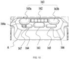
- a panel of the control module 16 includes a power button 161, an air volume display screen 162, an air volume control button 163, a water mist control button 164, a top-gear button 165 and a first indicator light 166.
- the power control button is used to control the misting fan 100 to be turned on or off, and can control the misting fan 100 to enter a remote control mode in a power-on state.
- the air volume display screen 162 includes a plurality of gear displays, and can reflect a current output air volume in real time.
- the air volume control button 163 includes a first control button 163a and a second control button 163b.
- the first control button 163a is used to decrease the air volume
- the second control button 163b is used to increase the air volume.
- the water mist control button 164 is used to control the water mist to be turned on or off. When the water mist is turned off, the spraying fan 100 can be used as a normal fan, which only blows air. When the water mist is turned on, the spraying fan 100 can perform spraying and blowing actions at the same time.
- the water mist control button 164 further includes a water mist multi-gear adjustment button 164a, and the water mist multi-gear adjustment button 164a controls a output power or pressure of the water pump through a circuit, and then controls the water mist to be sprayed at different sizes or rates and display on the display screen, so as to meet the different needs of different application scenarios.
- the top-gear button 165 is used to control the fan to directly connect to the motor to reach a maximum power and output a maximum air volume.
- the second indicator light 166 lights up or flashes and indicates that the misting fan has reached the maximum air volume.
- the second indicator light 166 also lights up or flashes accordingly.
- the second indicator light 166 may also be used to display the power level of the battery assembly.
- the present example further includes a control method of nozzles.
- the control module 16 can control the nozzles 113 to reduce the total amount of water output from the nozzles 113 for a period of time, while ensuring that a water output pressure from the nozzles 113 remains unchanged. That is, within a time T, when an outlet pressure of a single nozzle is P, a total amount of a water output from the nozzles is Q, and this process is recorded as a maximum water volume required under a given nozzle outlet pressure. Under an action of the control module, within the time T, when the outlet pressure of a single nozzle is P, the total amount of water output from the nozzles is Q', and this Q' ⁇ Q.
- the water volume can be reduced to 10%-90% of the maximum water output Q, that is, 0.1Q ⁇ Q' ⁇ 0.9Q. Further, the water volume can be reduced to 33% or 66% of the maximum water output Q, and the misting effect and cooling performance can also be guaranteed.
- the control module 16 controls the nozzles 113 to have a time interval t between an n th spraying of water mist and an n+1 th spraying of water mist, where n ⁇ 1.
- the control module realizes a pulsed water misting by controlling a start and stop of the water pump. An original outlet pressure is maintained when the n th and n+1 th spraying of water mist, which can ensure the required atomization effect and reduce the required water volume at the same time.
- a continuous water spray will affect the user on the contrary, causing it to form accumulated water spots at a sprayed place.
- a continuous blowing is combined with an interval time, so that the moisture on the user's skin, a surface of the clothing and a surface of working piece evaporates, keeping the work dry.
- a rotation function of the fan assembly can be combined to make the water mist cover a wider range.
- the control module 16 can control the misting fan 100 to rotate at a certain angle, or, when the misting fan 100 is in the spray interval, the control module 16 can control the misting fan 100 to reduce the rotation speed. That is, the misting fan 100 swings fast during spraying and swings slow after spraying and so on.
- control module 16 controls a part of the nozzles 113 to spray water mist, and the remaining nozzles stop spraying water mist.
- control module 16 calculates and reduces a water supply by reducing a working power and so on of the pump, so that the outlet pressure of the nozzles maintains at a predetermined pressure, the predetermined pressure is greater than or equal to 60 PSI and less than or equal to 1000 PSI, and can be selected to be greater than or equal to 80 PSI and less than or equal to 600PSI.
- the water pipe assembly 114 connecting each nozzle 113 includes a plurality of individually controlled pipelines, or the water pipe assembly 114 is composed of a main water circuit and a plurality of branch circuits corresponding to each of the nozzles 113.
- the connection between the branch circuit and the main water circuit is provided with a valve controlled by the control module.
- the valve is used to control the opening and closing of each branch. Since in this example, the nozzles 113 are equally spaced on a circumference of the fan, when some of the nozzles are controlled to be open and some of the nozzles are controlled to close, the opened nozzles should be spaced and evenly distributed on the misting fan.
- control module 16 controls at least part of the nozzles 113 to reduce a diameter of a water outlet. Or the diameters of the nozzles 113 are reduced by the user's operation.
- the above-mentioned methods for reducing the diameter of the nozzles include, but are not limited to rotating nozzles and so on.
- switching structures are provided within the nozzles, and the control module 16 or the user can change the diameters of the nozzles 113 through the switching structures.
- control module 16 calculates and reduces a water supply by reducing a working power and so on of the pump, so that the outlet pressure of the nozzles maintains at a predetermined pressure
- the predetermined pressure is greater than or equal to 60 PSI and less than or equal to 1000 PSI, and can be selected to be greater than or equal to 80 PSI and less than or equal to 600PSI.
- This example also includes a control method of a pump for protecting the operation of the pump.
- the control module 16 determines that the pump is blocked, and the control module 16 controls the pump to stop working.
- the control module 16 determines that the pump is dry-heated, and the control module 16 controls the pump to stop working.
- the panel of the control module 16 further includes a second indicator light 167. The second indicator light is used to display whether the pump is in a fault state. When the pump is in a blocked or a dry-heated condition, the control module 16 controls the second indicator light 167 to flash to prompt the user.
- the misting fan 100 When the misting fan 100 is set for a remote control through a power control, the misting fan 100 can be controlled and operated through other clients or platforms. As an example, the misting fan 100 can be controlled via a Bluetooth connection. It is to be understood that the misting fan 100 can also be controlled by other means, such as being controlled by communication control. In this example, when the misting fan 100 is controlled via the Bluetooth, it can control a wind speed of the misting fan 100, an amount of water sprayed, a startup and shutdown of the machine and a timed startup and shutdown of the machine, and can also control the switch of the indicator lights of the display screen.
- the misting fan 100 when the misting fan 100 is controlled via the Bluetooth, it can control a wind speed of the misting fan 100, an amount of water sprayed, a startup and shutdown of the machine and a timed startup and shutdown of the machine, and can also control the switch of the indicator lights of the display screen.
- a misting fan 200 has a part of the structure that is different from the previous example, and only the difference from the misting fan 100 of a first example is described here.
- the same structure uses the same reference signs, and is not stated again.
- the misting fan 200 includes a water inlet pipe 203, and the water inlet pipe 23 is connected to a pump.
- the pump is installed in the battery compartment 126, and the water inlet pipe 203 is led out from the battery compartment 126. Since both the battery pack and the pump are arranged in the battery compartment 126, in order to ensure the safety of the battery pack, a partition plate is provided in the battery compartment to divide an accommodating space into a plurality of mutually closed chambers.
- the rack 12 is provided with a fixing portion 202 to fix and receive the water inlet pipe 203.
- a fixing portion 202 to fix and receive the water inlet pipe 203.
- an end of the water inlet pipe 203 is generally equipped with a filter device 201, in order to ensure the cleanness of the filter device 201, the fixing portion at an end of the water inlet pipe 203 is located away from a position of the battery compartment 126, and is specifically located in the middle and upper portion of the first connecting assembly 121.
- the water inlet pipe 203 starting from the third connecting assembly 123 extends along the second connecting assembly 122, and extends from bottom to top to the middle portion of the first connecting assembly 121.
- the lower end of the filter device 201 is fixed in the fixing portion 202 upwards, and the water inlet pipe is 203 is in a first storage state 210.
- An upper end of the first connecting assembly 121 includes a housing surface parallel to a horizontal plane, or includes a groove, which can be used as a placement position of the water inlet pipe 203.
- the water inlet pipe 203 is in a second storage state, and this state can be used as a temporary placement position of the water inlet pipe 203, a fixing portion may be arranged as a storage fixing position.
- the misting fan 200 further includes a water outlet pipe 206.
- the water outlet pipe 206 is led out from the battery compartment 126 and introduced into the fan assembly through the first connecting assembly 121 and the second pivot 128 in sequence.
- the nozzles are arranged in a center stand 204 of a cover. Since there are multiple nozzles, and they are distributed at equal distances along the center stand 204, an annular water diversion pipe 205 is arranged in the center stand 204, supplying the water source in the water outlet pipe 206 to the nozzles respectively.
- a misting fan 300 can also be provided with a hook 310 matched with the handle portion 111e or the rack 12, so that the misting fan 100 can be hang to a preset height or a preset position.
- the same structures use the same reference signs as those in the first and second examples, and only the differences from the first and second examples are described here.
- the hook 310 is detachably connected to the misting fan 300.
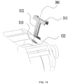
- the hook 310 includes a first hook 311, a second hook 313 and a connecting portion 312, and the connecting portion 312 connects the first hook 311 and the second hook 313.
- the first hook 311 is used for detachable connection with the second connecting assembly 122, or detachable connection with the handle portion 111e.
- the second hook 313 is used for detachable connection with a fixture in the external environment.
- the connecting portion 312 extends along a first direction 301, and the first direction 301 may be parallel to a setting plane of the fan assembly, may also be perpendicular to the setting plane, or may be at a certain angle to the setting plane, or the connecting portion 312 has a mechanism which can adjust the relative relationship between the first direction 301 and the setting plane, so as to adapt to different external environments.
- the hook 310 may also be a flexible structure or other detachable structures in other forms, which is not limited herein.
- a misting fan 400 has a part of the structure that is different from the previous example. Only the differences from the misting fan 100 of the first example are described here, and the same structure uses the same reference sings, and is not stated again.
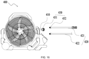
- the misting fan 400 includes a water inlet pipe 410, a first end of the water pipe 410 is connected to the nozzles 113 through a pipeline, and a second end extends outward from the misting fan 400 and is connected to a water source.
- the first end of the water inlet pipe 410 can be connected to a pump or an internal waterway system.
- the internal waterway system refers to the waterway system that connects the nozzles 113 inside the misting fan 400.
- the water inlet pipe 410 may extend from the battery compartment 126, or be integrated inside the housing of the rack and extend from one side of the misting fan 400.
- the misting fan 400 is further provided with a water distribution pipe 420 connected to the water inlet pipe 410, and the water distribution pipe 420 is detachably connected with the water inlet pipe 410.
- the water distribution pipe 420 includes at least a first water distribution pipe 421 and a second water distribution pipe 422.
- the first water distribution pipe 421 is used to connect to a first external water source
- the second water distribution pipe 422 is used to connect to a second external water source.
- the first external water source is a static water source
- the second external water source is a flowing water source.
- the static water source is to be understood as water contained in a reservoir, such as water in a bucket.
- the second external water source is specifically the flowing water source, and the flowing water source is to be understood as a water source having a certain flow rate, such as tap water.
- a quick release mechanism 430 is provided at the connection between the water inlet pipe 410 and the water distribution pipe 420.
- the quick release device 430 includes a first connecting head 431 provided at an end of the water inlet pipe 410 and a second connecting head 432 disposed at an end of the water distribution pipe 420.
- the first connection head 431 and the second connection head 432 are configured to be detachably connected to each other. Specifically, they can be connected in the form of threaded caps and threads, or they can be connected by means of compression type, socket type, and so on, which is not limited herein.
- the water distribution pipe 420 is provided with a connection head or a filter device, and the connection head is used to connect an external dynamic water source or to extend the pipeline.
- a structure for accommodating the water inlet pipe 410 or the water distribution pipe 420 is also arranged in the rack or the battery compartment.
- the water inlet pipe 410 is provided with a pressure-stabilizing valve, which is used to reduce the water hammer phenomenon, and can be optionally arranged on the upstream of the pump.
- a pressure-stabilizing valve which is used to reduce the water hammer phenomenon, and can be optionally arranged on the upstream of the pump.
- the one-way valve of the pump is generally made of plastic. Under the impact of this moment, it may cause deformation, breakage and fall off, etc., which affects the supply of water flow to the misting fan.
- the pressure-stabilizing valve can reduce the damage to the pump structure caused by the water hammer effect, improve the stability of the misting fan, and prolong the service life.
Landscapes
- Engineering & Computer Science (AREA)
- Mechanical Engineering (AREA)
- General Engineering & Computer Science (AREA)
- Chemical & Material Sciences (AREA)
- Combustion & Propulsion (AREA)
- Dispersion Chemistry (AREA)
- Transportation (AREA)
- Structures Of Non-Positive Displacement Pumps (AREA)
Abstract
Description
- This application claims priority to
Chinese Patent Application No. 202011479659.1 filed with the China National Intellectual Property Administration (CNIPA) on Dec. 16, 2020 Chinese Patent Application No. 202111133193.4 filed with the CNIPAon Sep. 27, 2021 Chinese Patent Application No. 202111133224.6 filed with the CNIPAon Sep. 27, 2021 Chinese Patent Application No. 202111133626.6 filed with the CNIPAon Sep. 27, 2021 Chinese Patent Application No. 202122357468.4 filed with the CNIPA on Sep. 27, 2021 - This application relates to a misting fan.
- A misting fan is usually connected to a commercial power as an energy source, and the misting fan has great limitations and cannot be adapted to some places far from the commercial power or lack of sockets, which seriously limits the use of the misting fan. For a misting fan connected to a small battery pack, it cannot be applied to the spray requirements of large venues, large areas, and high flow rates, which further limits the range of application of the misting fan. How to provide a misting fan with compact structure, high power output, long battery life and convenient operation is a technical problem to be urgently solved by those skilled in the art.
- This application provides a misting fan with a good misting effect and a convenient operation.
- This application adopts the following technical solutions:
A misting fan includes: a fan assembly including a fan blade and a motor configured to drive the fan blade; a nozzle located on the fan assembly and configured to spray water mist; and a rack configured to support the fan assembly. The rack includes an extending portion configured to be placed and extending in a plane. The misting fan is provided with a moving wheel for walking, and the moving wheel is provided in the extending portion. - In an example, the misting fan further includes a handle assembly cooperated with the moving wheel, and the handle assembly is provided on an end away from the moving wheel.
- In an example, the handle assembly is set as a telescopic structure, and has a first state and a second state relative to the rack; when the handle assembly is in the first state relative to the rack, the handle assembly is in a contracted state; when the handle assembly is in the second state relative to the rack, the handle assembly is in an extended state.
- In an example, when the handle assembly is in the second state, the misting fan walks at a relative angle to a walking road and the moving wheel serves as a pivot at this time.
- In an example, the misting fan further includes a power supply assembly and a battery compartment configured to accommodate the power supply assembly, the power supply assembly is used to supply power to the motor, and the battery compartment is arranged at an end of the rack away from the moving wheel.
- In an example, an extending direction of the battery compartment and the extending portion obliquely intersect and form a preset included angle, and the acute angle of the included angle is greater than or equal to 0° and less than or equal to 90°.
- In an example, the rack includes a first connecting assembly, a second connecting assembly and a third connecting assembly, the second connecting assembly is connected to the first connecting assembly and the third connecting assembly respectively, the first connecting assembly is connected to the second connecting assembly to form a first buffer portion; the first buffer portion obliquely intersects with the second connecting assembly and the second connecting assembly; the third connecting assembly is connected to the second connecting assembly to form a second buffer portion, the second buffer portion obliquely intersects with the third connecting assembly and the second connecting assembly.
- In an example, the misting fan further includes a power supply assembly and a battery compartment configured to accommodate the power supply assembly; the third connecting assembly is provided on a side of the rack away from the moving wheel, the third connecting assembly is formed by a set of substantially parallel connecting rods, the battery compartment is at least partially disposed between the parallel-arranged connecting rods of the third connecting assembly.
- In an example, a handle assembly is telescopic relative to the second connecting assembly, the handle assembly includes a grip portion, and the grip portion is provided on an outer side of the third connecting assembly, the grip portion and third connecting assembly are distributed at least partially around the battery compartment.
- In an example, the rack partially surrounds the peripheral side of the fan assembly, and is connected to the fan assembly by at least a first pivot.
- This application further adopts the following technical solutions:
A misting fan includes: a fan assembly including a fan blade and a motor configured to drive the fan blade; a nozzle located on the fan assembly and configured to spray water mist; and a rack configured to support the fan assembly. The misting fan further includes a moving wheel that provides the misting fan with a walking ability and is in contact with a placement plane. The misting fan at least includes a first standing posture and a second standing posture, and different positions of the rack are in contact with the placement plane and provide support when the misting fan is in different standing postures. - A misting fan includes: a fan assembly including a fan blade and a motor configured to drive the fan blade; a plurality of nozzles, wherein the plurality of nozzles are located on the fan assembly and configured to spray water mist; and a rack configured to support the fan assembly. The fan assembly further includes a control module configured to control the plurality of nozzles to reduce a total amount of a water output from the plurality of nozzles over a period of time, while ensuring that a pressure of a water output of the plurality of nozzles remains unchanged.
- In an example, under an action of the control module, the plurality of nozzles have a time interval t between an nth spraying of water mist and an n+1th spraying of water mist, where n≥1.
- In an example, under an action of the control module, some of the plurality of nozzles spray water mist, and the remaining ones of the plurality of nozzles stop spraying water mist.
- In an example, each of the plurality of nozzles includes a switching structure configured to switch a diameter of a water outlet of the plurality of nozzles.
- In an example, the fan assembly is connected to the rack by at least a pivot along which the fan assembly is movable relative to the rack.
- In an example, the misting fan further includes a housing assembly. The housing assembly forms an accommodating space. The fan assembly is at least partially disposed in the accommodating space. The housing assembly includes a main body portion and a cover body, the nozzles are provided on the cover body, and the cover body is rotatable relative to the main body portion.
- A misting fan includes: a fan assembly including a fan blade and a motor configured to drive the fan blade; a nozzle located on the fan assembly and configured to spray water mist; and a rack configured to support the fan assembly. The misting fan further includes a control module configured to control the nozzle to reduce a total amount of a water output from the nozzle over a period of time, while ensuring that a pressure of the water output of the nozzle remains unchanged; and under an action of the control module, the nozzle has a time interval t between an nth spraying of water mist and an n+1th spraying of water mist, where n≥1.
- A control method of a misting fan is provided. The misting fan includes: a fan assembly including a fan blade and a motor configured to drive the fan blade to rotate; a plurality of nozzles, wherein the plurality of nozzles are located on the fan assembly and configured to spray water mist; a rack configured to support the fan assembly. Within a time T, when an outlet pressure of a single one of the plurality of nozzles is P, a total amount of a water output from the plurality of nozzles is Q. Under an action of a control module, within the time T, when the outlet pressure of the single one of the plurality of nozzles is P, the total amount of the water output from the plurality of nozzles is Q', and Q'<Q.
- In an example, under the action of the control module, the plurality of nozzles have a time interval t between an nth spraying of water mist and an n+1th spraying of water mist, where n≥1; or, under the action of the control module, some of the plurality of nozzles spray water mist, and the remaining ones of the plurality of nozzles stop spraying water mist; or, under the action of the control module, a diameter of the plurality of nozzles decreases.
- In an example, the misting fan includes a pump. When the pump is working, when it is detected that a working current of the pump is greater than a maximum rated working current, the control module determines that the pump is blocked, and the control module controls the pump to stop working. When the pump is working, when it is detected that the working current of the pump is less than the minimum rated working current for a continuous time t0, the control module determines that the pump is dry-heated, and the control module controls the pump to stop working.
- A misting fan includes: a fan assembly including a fan blade and a motor configured to drive the fan blade; a nozzle located on the fan assembly and configured to spray water mist; a rack configured to support the fan assembly; a power supply assembly mounted to the rack and configured to power the misting fan; and a water inlet pipe with one end connected to the nozzle through a pipeline, and one end extending outward from the misting fan and connected to a water source.
- In an example, the misting fan includes a water distribution pipe detachably connected to the water inlet pipe.
- In an example, the water distribution pipe includes at least a first water distribution pipe and a second water distribution pipe, the first water distribution pipe is configured to connect to a first external water source, and the second water distribution pipe is configured to connect to a second external water source.
- In an example, the first external water source is a static water source, and the second external water source is a flowing water source.
- In an example, a quick release mechanism is provided at a connection between the water inlet pipe and the water distribution pipe.
- In an example, the misting fan includes a pump, the pump connects the nozzle and the water inlet pipe through a pipeline, and the rack is further provided with a housing configured to accommodate the pump.
- In an example, the water inlet pipe is provided with a pressure-stabilizing valve.
- In an example, the rack includes a first connecting assembly, a second connecting assembly and a third connecting assembly, the second connecting assembly is connected to the first connecting assembly and the third connecting assembly respectively, the first connecting assembly is connected to the second connecting assembly to form a first buffer portion; the first buffer portion obliquely intersects with the second connecting assembly and the second connecting assembly; the third connecting assembly is connected to the second connecting assembly to form a second buffer portion, the second buffer portion obliquely intersects with the third connecting assembly and the second connecting assembly.
- In an example, the misting fan further includes a power supply assembly and a battery compartment configured to accommodate the power supply assembly; the third connecting assembly is provided on a side of the rack away from the moving wheel, the third connecting assembly is formed by a set of substantially parallel connecting rods, the battery compartment is at least partially disposed between the parallel-arranged connecting rods of the third connecting assembly.
- In an example, a diameter of a complete machine of the misting fan is greater than or equal to 550 mm and less than or equal to 1000 mm.
- The application provides a misting fan with high output power, strong stability and easy operation; provides a misting fan with high output power, water saving and good atomization effect; the misting fan is more convenient to use and can be connected to different external water sources more easily.
-
-
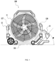
FIG. 1 is a front view of a misting fan; -
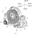
FIG. 2 is a perspective view of the misting fan inFIG. 1 ; -
FIG. 3 is a perspective view of the misting fan inFIG. 1 from another point of view; -
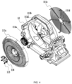
FIG. 4 is an exploded view of the misting fan inFIG. 1 ; -
FIG. 5 is an exploded view of the misting fan inFIG. 1 from another point of view; -
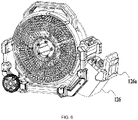
FIG. 6 is a perspective view of the misting fan inFIG. 1 after removing a handle assembly and opening a battery compartment cover; -
FIG. 7 is a sectional view of the misting fan inFIG. 1 ; -
FIG. 8 is a right view of the misting fan inFIG. 1 ; -
FIG. 9 is a perspective view of the misting fan inFIG. 1 when the handle assembly is in an extended position; -
FIG. 10 is an enlarged view of the structure of part A inFIG. 8 ; -
FIG. 11 is a perspective view of a misting fan in a second example of the present application; -
FIG. 12 is a schematic diagram of a direction of a water inlet pipe of the misting fan in the second example of the present application; -
FIG. 13 is a schematic diagram of a misting fan in a hanging state in a third example of the present application; -
FIG. 14 is a schematic diagram of a hook in a first way of setting in the third example of the present application; -
FIG. 15 is a schematic diagram of the hook in a second way of setting in the third example of the present application; and -
FIG. 16 is a schematic diagram of a misting fan in a fourth example of the present application. -
FIGS. 1 to 2 show a mistingfan 100, which blows wind with water mist through functions of blowing and spraying, and can cool and humidify a preset site. The mistingfan 100 provided in this example has a large shape and a high power, and can perform large-scale and continuous cooling and humidification of large venues, such as indoor and outdoor large stadiums, football fields, scenic spots, and the like. When the mistingfan 100 works in a place far from a water source, the mistingfan 100 can be connected to an external water source such as a bucket. When the mistingfan 100 works indoors or in a place close to the water source, it can also be directly connected to a tap water pipe. Specifically, the mistingfan 100 includes ahost 11, arack 12 and apower supply assembly 13. Thehost 11 and thepower supply assembly 13 are both connected to therack 12, thehost 11 is also electrically connected with thepower supply assembly 13, and thepower supply assembly 13 is detachably connected to therack 12. - As shown in
FIGS. 3 to 5 , thehost 11 includes a housing assembly 111, a fan assembly 112 and anozzle 113. The housing assembly 111 forms anaccommodating space 111a, and the fan assembly 112 is at least partially disposed in theaccommodating space 111a. The housing assembly 111 includes amain body portion 111b and acover body 111c. Themain body portion 111b is formed around theaccommodating space 111a, and thecover body 111c is arranged around themain body portion 111b and connected to themain body portion 111b. Thecover body 111c also at least partially closes themain body portion 111b and forms a through hole through which airflow flows in or out. Specifically, thecover body 111c has a mesh structure and is arranged on two sides of themain body portion 111b. Thecover body 111c is further formed with acavity 111d for installing or supporting the fan assembly 112, and the fan assembly 112 is installed to thehost 11 through thecavity 111d. Thecover body 111c is configured to be a structure rotatable with respect to themain body portion 111b. Specifically, the rotation is set to be smaller than the rotation speed offan blades 112a, and the rotation of thecover body 111c drives thenozzle 113 to rotate, which is easier to combine with the rotating airflow, and plays a role of uniformly atomizing water mist. The water mist has a wider diffusion range, and further achieves a result of improving a cooling effect. - The fan assembly 112 includes the
fan blades 112a and amotor 112b, and themotor 112b is used to drive thefan blades 112a to rotate around an axis of themotor 112b. Themotor 112b is sealed by a waterproof material to prevent water mist from entering the motor under an action of the environment. Specifically, for example, the waterproof material can be a plastic film and so forth, and the motor is sealed by a plastic film through a process such as hot air and so on. - The
nozzle 113 is used to spray water mist, and thenozzle 113 is mounted to the housing assembly 111 or the fan assembly 112. When thepower supply assembly 13 is installed to thehost 11, the mistingfan 100 is activated. The water mist is sprayed from thenozzle 113 to the external environment, and thefan blade 112a rotates to generate an air flow to blow the water mist sprayed from thenozzle 113 into the air, thereby making the temperature of the air in the environment drops. In this example, thenozzle 113 is chosen to be a detachable and washable spray head, which is detachably connected to the housing assembly 111 or the fan assembly 112. Further, when the spray head is detachable, thenozzle 113 is provided with a filter screen. The filter screen is used to filter the water supply, which can reduce the frequency of disassembly and cleaning of the spray head, and the filter screen is detachably connected to the spray head. It is to be understood that thenozzle 113 is also connected with awater pipe assembly 114. Thewater pipe assembly 114 includes a water pump and a water-leading pipe. The water-leading pipe connects the water pump and thenozzle 113. Under the action of the water pump, the water is sucked into the water-leading pipe and can be transported to thenozzle 113 in a high pressure state, so as to be sprayed in an atomized state. In order to avoid interference between the water leading pipe and other components, the housing assembly 111 is further provided with a receiving portion for accommodating the water leading pipe. As an implementation manner, the accommodating portion may be provided as a buckle for clamping the water leading pipe, or the housing assembly 111 itself forms an accommodating groove for accommodating or fixing the water leading pipe, so that the water-leading pipe can be closely attached to the housing assembly 111 to avoid interference with other components. - In order to illustrate the technical solution of the present application, a front side, a rear side, a left side, a right side, an upper side and a lower side as shown in
FIG. 2 are further defined. As shown inFIGS. 1 to 5 , in afirst plane 102 perpendicular to the rotation axis of themotor 112b, the projection of therack 12 in thefirst plane 102 along the direction of rotation axis is substantially rectangular. Therein, therack 12 includes an extending portion that can be placed and extends in a plane parallel to aplacement plane 101 of the external environment. Moving wheels are arranged within the extending portion, in particular at an end of the extending portion. Therack 12 partially surrounds a peripheral side of the fan assembly 112, and is connected to the fan assembly through at least afirst pivot 127, and further, therack 12 further includes asecond pivot 128. The fan assembly 112 can rotate as a whole around the above-mentioned pivots, thereby driving the water mist sprayed from the nozzle to cover a larger area. - The
rack 12 includes a first connectingassembly 121, a second connectingassembly 122 and a third connectingassembly 123. The second connectingassembly 122 forms a fixed connection with the first connectingassembly 121 and the third connectingassembly 123 respectively. In fact, the first connectingassembly 121, the second connectingassembly 122 and the third connectingassembly 123 can also be configured to be integrally formed, as long as the three of them meet the structural strength requirements. Therack 12 is formed with an accommodating groove for accommodating thehost 11, and thehost 11 is at least partially disposed in the accommodating groove and is fixedly or detachably connected with therack 12. In this example, afirst buffer portion 124 is provided at the connection between the second connectingassembly 122 and the first connectingassembly 121, and thefirst buffer portion 124 obliquely intersects with the first connectingassembly 121 and the second connectingassembly 122 at the same time. Asecond buffer portion 125 is provided at the connection between the second connectingassembly 122 and the third connectingassembly 123, and thesecond buffer portion 125 obliquely intersects with the second connectingassembly 122 and the third connectingassembly 123 at the same time. While saving the size of the whole machine, it is more convenient to switch the misting fan among different standing postures. In this example, the first connectingassembly 121, the second connectingassembly 122 and the third connectingassembly 123 also extend in respective planes, thereby forming a plane on which the mistingfan 100 can be placed. That is, the first connectingassembly 121, the second connectingassembly 122, and the third connectingassembly 123 can all be used as the extending portion and can be used for placement of the mistingfan 100. - Specifically, the
first buffer portion 124 and thesecond buffer portion 125 are shell-shaped with multiple contact surfaces, and the first connectingassembly 121, the second connectingassembly 122, and the third connectingassembly 123 include a plurality of connecting rods that are spaced apart. The connecting rods are connected to the aforementioned buffer portions. The mistingfan 100 includes at least a first standing posture and a second standing posture. When the misting fan is in different standing postures, different positions of the rack are in contact with theplacement plane 101 and provide support. The standing postures mean that the fan can be stably supported on theplacement plane 101 without relying on external force, and the above-mentioned standing postures do not exclude the situation that the misting fan moves along theplacement plane 101 in these postures. In this example, part of end surfaces of the first and second buffer portions can be used as placement surfaces of the mistingfan 100. At this time, a plane where the end surfaces are located is tangent to a lower edge of the movingwheel 14, and the second connectingassembly 122 is located above the plane or being flush with the plane. This enables the fan to stand stably in the first standing posture shown inFIG. 2 . This example has the second standing posture. For example, the first connectingassembly 121 is used as a base. At this time, an other end of the first connectingassembly 121 is provided with a shell-shaped end. The shell-shaped end, a lower edge of the movingwheel 14 and an end of thefirst buffer portion 124 is used as a support for standing. That is, forming the above-mentioned extending portion. The first connectingassembly 122 is located above or flush with the plane, which can ensure the stable standing of the misting fan. - As shown in
FIGS. 1 ,2 and6 , thesecond buffer portion 125 is further provided with abattery compartment 126 for connecting thepower supply assembly 13. As an example, thepower supply assembly 13 is provided as one or more battery packs that can be directly mounted to thebattery compartment 126. The first connectingassembly 121, the second connectingassembly 122 and the third connectingassembly 123 all include a set of substantially parallel connecting rods. Thebattery compartment 126 is substantially disposed in a joint space of the substantially parallel connecting rods of the third connectingassembly 123 and fully utilizes the space between thethird connection component 123 and thehost 11. Wherein, thebattery compartment 126 actually further fully utilizes the joint space of the connecting rods of the third connectingassembly 123. Thebattery compartment 126 is substantially in the structure of a rectangular parallelepiped, the interior of which is hollow, and can fit with thepower supply assembly 13. Inside thebattery compartment 126, it is further provided with a joint portion or a connection terminal (not shown in the figure) for connecting the battery pack, so that when the battery pack is inserted into thebattery compartment 126, the electrical connection with a control circuit can be realized. In this solution, thebattery compartment 126 is further provided with acompartment cover 126a, which can rotate around a rotation axis and has a first position for closing a space in thebattery compartment 126 and a second position for opening the space in thebattery compartment 126. It can be understood that thecompartment cover 126a is disposed on an end of thebattery compartment 126 away from the third connectingassembly 123, so as to avoid generating interference with the third connectingassembly 123 when thecompartment cover 126a is converted between the first position and the second position. Thebattery compartment 126 further extends along the extending direction of thesecond buffer portion 125 , so as to better fit with the connecting rods of the third connectingassembly 123, so as to make the connection relation between thebattery compartment 126 and the third connectingassembly 123 is closer. In fact, thebattery compartment 126 is disposed near the second connectingassembly 122, so that after thebattery compartment 126 is installed with the battery pack, a center of gravity of the entire mistingfan 100 is closer to a lower side. This makes the mistingfan 100 more stable when it is placed and not easy to fall under the impact of an external environment. The second connectingassembly 122 substantially extends in a plane perpendicular to an up-down direction, and an outer contour of thebattery compartment 126 is provided above the plane. That is, when the mistingfan 100 is placed normally, the outer contour of thebattery compartment 126 does not generate interference with the second connectingassembly 122, and a lower surface of the second connectingassembly 122 is used as the contact surface. In this example, it is further provided that an acute angle α of an included angle of theplacement plane 101 between the extending direction of thebattery compartment 126 is greater than or equal to 0° and less than or equal to 90°, optionally greater than or equal to 10° and less than or equal to 75°, so as to match with thesecond buffer portion 125. - In this example, since a rated power of the misting
fan 100 is large, in order to satisfy the function output of the mistingfan 100 for a long time, thepower supply assembly 13 is provided to have a large capacity, so that it has a large weight. In addition, thehost 11 occupies a large space in the up-down direction and in a left-right direction due to a need to satisfy the blowing or spraying of a large area. Specifically, a size of thehost 11 in the up-down direction is greater than or equal to 400 mm and less than or equal to 550 mm; a size of thehost 11 in the left-right direction is greater than or equal to 400 mm and less than or equal to 500 mm. When thehost 11 is installed on therack 12, a diameter of the entire mistingfan 100 is greater than or equal to 550 mm and less than or equal to 1000 mm. Specifically, a size of the entire mistingfan 100 in the up-down direction is set to be greater than or equal to 600 mm and less than or equal to 750 mm, and a size of the entire mistingfan 100 in the left-right direction is set to be greater than or equal to 650 mm and less than or equal to 800 mm. In this example, thehost 11 of the mistingfan 100 is further provided with ahandle portion 111e configured to be lifted and carried, and thehandle portion 111e further occupies a preset height in the up-down direction, so that a size of the entire machine of the mistingfan 100 in the up-down direction is greater than or equal to 620mm and less than or equal to 720mm. Through the above arrangement, an air volume that can be blown out by the mistingfan 100 provided in this example can reach 5000 cfm, thereby achieving a better cooling effect. - As shown in
FIG. 9 , as an example, the mistingfan 100 is further provided with the movingwheel 14 configured to move. Specifically, the movingwheel 14 is provided on thefirst buffer portion 124 and can rotate around a rotation axis. Specifically, the rotating shaft is provided on the first connectingcomponent 121 or the second connectingcomponent 122. As an example, two movingwheels 14 are provided, which are respectively located on the connecting rods of the first connectingassembly 121 or the second connectingassembly 122. It can be understood that one or more movingwheels 14 can also be provided, so that they can be optionally provided on the connecting rods and are configured to move the mistingfan 100. The movingwheel 14 has a circumferential outer contour, and when it is mounted to the first connectingassembly 121 or the second connectingassembly 122, its outer contour is substantially flush with theplacement plane 101 or is located on an upper side of theplacement plane 101. Thus, when the mistingfan 100 is normally placed, the outer contour of the movingwheel 14 does not interfere with the second connectingassembly 122, and a lower surface of the second connectingassembly 122 is used as a contact surface, or the outer contour of the movingwheel 14 and the lower surface of the second connectingassembly 122 are used as the contact surface at the same time. In order to facilitate the movement of the mistingfan 100, ahandle assembly 15 which is matched with the movingwheel 14 is further provided. Specifically, thehandle assembly 15 includes amain body portion 151 extending substantially in a linear direction and agrip portion 152 connected to themain body portion 151. Thegrip portion 152 includes an inner contour and an outer contour. The inner contour is arranged around thebattery compartment 126, and the outer contour is configured to be flush with theplacement plane 101 in the up-down direction or to be on the upper side of theplacement plane 101. Thegrip portion 152 includes a first grip portion 152a extending in the same direction as thebattery compartment 126 and a second grip portion 152b substantially parallel to theplacement plane 101. The first grip portion 152a includes two oppositely disposed units, and the second gripping portion 152b is configured as a semi-enclosed annular member connecting the two first gripping portions 152a. Since the mistingfan 100 of this example has various standing postures, the above structure combined with the positions of the third connectingcomponent 123 and thebattery compartment 126 can fully protect the safety of thebattery compartment 126 in different standing postures. Even when the fan is in a walking state, it can also improve the stability of the battery pack and reduce the vibration of the battery pack. Based on the size of the mistingfan 100 in this example, the arrangement of thebattery compartment 126 can make the whole machine have a more stable center of gravity. - The
handle assembly 15 is further provided as a telescopic structure, and is arranged on an end of the second connectingassembly 122 away from the movingwheel 14. In this example, the connecting rods of the second connectingassembly 122 are provided as hollow structure, which can be configured to accommodate at least part of thehandle assembly 15. - The
handle assembly 15 has a first state and a second state. When thehandle assembly 15 is in the first state, thehandle assembly 15 is in a retracted state, and at this time, the inner contour of thegrip portion 152 is substantially fitted with or close to thebattery compartment 126. Themain body portion 151, the first grip portion 152a and the second grip portion 152b surround each side surface of thebattery compartment 126, respectively. When thehandle assembly 15 is in the second state, thehandle assembly 15 is in an extended state. At this time, themain body portion 151 of thehandle assembly 15 protrudes from the second connectingassembly 122 to a preset length, so as to facilitate holding. At this time, it is possible to make the mistingfan 100 is dragged at a certain angle with the ground, and can roll forward along the ground under the action of rollers. In order to facilitate the operation, when the mistingfan 100 is dragged at the certain angle with the ground, its center of gravity is set to be located between thegrip portion 152 and the movingwheel 14. More specifically, when the mistingfan 100 is dragged at the certain angle with the ground, its center of gravity is set close to the movingwheel 14. - As shown in
FIG. 2 andFIG. 8 , the mistingfan 100 is further provided with acontrol module 16 configured to control an output mode and an output power. Thecontrol module 16 is provided on thethird connection assembly 123, located between the two connecting rods of thethird connection assembly 123, and is located at an upper end of thebattery compartment 126. Specifically, a panel of thecontrol module 16 includes apower button 161, an airvolume display screen 162, an airvolume control button 163, a watermist control button 164, a top-gear button 165 and afirst indicator light 166. The power control button is used to control the mistingfan 100 to be turned on or off, and can control the mistingfan 100 to enter a remote control mode in a power-on state. In addition, the airvolume display screen 162 includes a plurality of gear displays, and can reflect a current output air volume in real time. The airvolume control button 163 includes afirst control button 163a and asecond control button 163b. Thefirst control button 163a is used to decrease the air volume, and thesecond control button 163b is used to increase the air volume. The watermist control button 164 is used to control the water mist to be turned on or off. When the water mist is turned off, the sprayingfan 100 can be used as a normal fan, which only blows air. When the water mist is turned on, the sprayingfan 100 can perform spraying and blowing actions at the same time. As an example, the watermist control button 164 further includes a water mistmulti-gear adjustment button 164a, and the water mistmulti-gear adjustment button 164a controls a output power or pressure of the water pump through a circuit, and then controls the water mist to be sprayed at different sizes or rates and display on the display screen, so as to meet the different needs of different application scenarios. The top-gear button 165 is used to control the fan to directly connect to the motor to reach a maximum power and output a maximum air volume. When the top-gear button 165 is pressed, thesecond indicator light 166 lights up or flashes and indicates that the misting fan has reached the maximum air volume. When the maximum air volume is reached by pressing thesecond control button 163b for many times, thesecond indicator light 166 also lights up or flashes accordingly. In other examples, thesecond indicator light 166 may also be used to display the power level of the battery assembly. - The present example further includes a control method of nozzles. The
control module 16 can control thenozzles 113 to reduce the total amount of water output from thenozzles 113 for a period of time, while ensuring that a water output pressure from thenozzles 113 remains unchanged. That is, within a time T, when an outlet pressure of a single nozzle is P, a total amount of a water output from the nozzles is Q, and this process is recorded as a maximum water volume required under a given nozzle outlet pressure. Under an action of the control module, within the time T, when the outlet pressure of a single nozzle is P, the total amount of water output from the nozzles is Q', and this Q'<Q. Specifically, under the action of the control module, the water volume can be reduced to 10%-90% of the maximum water output Q, that is, 0.1Q≤Q'≤0.9Q. Further, the water volume can be reduced to 33% or 66% of the maximum water output Q, and the misting effect and cooling performance can also be guaranteed. - The above example for reducing water volume includes but is not limited to the following examples:
In an example, thecontrol module 16 controls thenozzles 113 to have a time interval t between an nth spraying of water mist and an n+1th spraying of water mist, where n≥1. The control module realizes a pulsed water misting by controlling a start and stop of the water pump. An original outlet pressure is maintained when the nth and n+1th spraying of water mist, which can ensure the required atomization effect and reduce the required water volume at the same time. As a user, when using the misting fan, a continuous water spray will affect the user on the contrary, causing it to form accumulated water spots at a sprayed place. As the pulsed water spray has the required atomization effect, a continuous blowing is combined with an interval time, so that the moisture on the user's skin, a surface of the clothing and a surface of working piece evaporates, keeping the work dry. In this example, a rotation function of the fan assembly can be combined to make the water mist cover a wider range. Specifically, when the mistingfan 100 is in a spray interval, thecontrol module 16 can control the mistingfan 100 to rotate at a certain angle, or, when the mistingfan 100 is in the spray interval, thecontrol module 16 can control the mistingfan 100 to reduce the rotation speed. That is, the mistingfan 100 swings fast during spraying and swings slow after spraying and so on. - In another example, the
control module 16 controls a part of thenozzles 113 to spray water mist, and the remaining nozzles stop spraying water mist. At the same time, thecontrol module 16 calculates and reduces a water supply by reducing a working power and so on of the pump, so that the outlet pressure of the nozzles maintains at a predetermined pressure, the predetermined pressure is greater than or equal to 60 PSI and less than or equal to 1000 PSI, and can be selected to be greater than or equal to 80 PSI and less than or equal to 600PSI. In this example, thewater pipe assembly 114 connecting eachnozzle 113 includes a plurality of individually controlled pipelines, or thewater pipe assembly 114 is composed of a main water circuit and a plurality of branch circuits corresponding to each of thenozzles 113. The connection between the branch circuit and the main water circuit is provided with a valve controlled by the control module. The valve is used to control the opening and closing of each branch. Since in this example, thenozzles 113 are equally spaced on a circumference of the fan, when some of the nozzles are controlled to be open and some of the nozzles are controlled to close, the opened nozzles should be spaced and evenly distributed on the misting fan. - In another example, the
control module 16 controls at least part of thenozzles 113 to reduce a diameter of a water outlet. Or the diameters of thenozzles 113 are reduced by the user's operation. The above-mentioned methods for reducing the diameter of the nozzles include, but are not limited to rotating nozzles and so on. Specifically, switching structures are provided within the nozzles, and thecontrol module 16 or the user can change the diameters of thenozzles 113 through the switching structures. At the same time, thecontrol module 16 calculates and reduces a water supply by reducing a working power and so on of the pump, so that the outlet pressure of the nozzles maintains at a predetermined pressure, the predetermined pressure is greater than or equal to 60 PSI and less than or equal to 1000 PSI, and can be selected to be greater than or equal to 80 PSI and less than or equal to 600PSI. - This example also includes a control method of a pump for protecting the operation of the pump. when the pump is working, when it is detected that a working current of the pump is greater than a maximum rated working current, the
control module 16 determines that the pump is blocked, and thecontrol module 16 controls the pump to stop working. When the pump is working, when it is detected that the working current of the pump is less than the minimum rated working current for a continuous time t0, thecontrol module 16 determines that the pump is dry-heated, and thecontrol module 16 controls the pump to stop working. As shown inFIG. 10 , the panel of thecontrol module 16 further includes asecond indicator light 167. The second indicator light is used to display whether the pump is in a fault state. When the pump is in a blocked or a dry-heated condition, thecontrol module 16 controls thesecond indicator light 167 to flash to prompt the user. - When the misting
fan 100 is set for a remote control through a power control, the mistingfan 100 can be controlled and operated through other clients or platforms. As an example, the mistingfan 100 can be controlled via a Bluetooth connection. It is to be understood that the mistingfan 100 can also be controlled by other means, such as being controlled by communication control. In this example, when the mistingfan 100 is controlled via the Bluetooth, it can control a wind speed of the mistingfan 100, an amount of water sprayed, a startup and shutdown of the machine and a timed startup and shutdown of the machine, and can also control the switch of the indicator lights of the display screen. - In a second example as shown in
FIGS. 11 and12 , a mistingfan 200 has a part of the structure that is different from the previous example, and only the difference from the mistingfan 100 of a first example is described here. The same structure uses the same reference signs, and is not stated again. - The misting
fan 200 includes awater inlet pipe 203, and the water inlet pipe 23 is connected to a pump. In this example, the pump is installed in thebattery compartment 126, and thewater inlet pipe 203 is led out from thebattery compartment 126. Since both the battery pack and the pump are arranged in thebattery compartment 126, in order to ensure the safety of the battery pack, a partition plate is provided in the battery compartment to divide an accommodating space into a plurality of mutually closed chambers. - The
rack 12 is provided with a fixingportion 202 to fix and receive thewater inlet pipe 203. Specifically, according to the length of thewater inlet pipe 203, there may be a plurality of fixingportions 202, which are respectively provided on the first connecting assembly, the second connecting assembly and the third connecting assembly. Since an end of thewater inlet pipe 203 is generally equipped with afilter device 201, in order to ensure the cleanness of thefilter device 201, the fixing portion at an end of thewater inlet pipe 203 is located away from a position of thebattery compartment 126, and is specifically located in the middle and upper portion of the first connectingassembly 121. Thus, thewater inlet pipe 203 starting from the third connectingassembly 123 extends along the second connectingassembly 122, and extends from bottom to top to the middle portion of the first connectingassembly 121. At this time, the lower end of thefilter device 201 is fixed in the fixingportion 202 upwards, and the water inlet pipe is 203 is in afirst storage state 210. - An upper end of the first connecting
assembly 121 includes a housing surface parallel to a horizontal plane, or includes a groove, which can be used as a placement position of thewater inlet pipe 203. At this time, thewater inlet pipe 203 is in a second storage state, and this state can be used as a temporary placement position of thewater inlet pipe 203, a fixing portion may be arranged as a storage fixing position. - As shown in
FIGS. 11 and12 , the mistingfan 200 further includes awater outlet pipe 206. Thewater outlet pipe 206 is led out from thebattery compartment 126 and introduced into the fan assembly through the first connectingassembly 121 and thesecond pivot 128 in sequence. In this example, the nozzles are arranged in acenter stand 204 of a cover. Since there are multiple nozzles, and they are distributed at equal distances along thecenter stand 204, an annularwater diversion pipe 205 is arranged in thecenter stand 204, supplying the water source in thewater outlet pipe 206 to the nozzles respectively. - In a third example shown in
FIGS. 13 to 15 , a mistingfan 300 can also be provided with ahook 310 matched with thehandle portion 111e or therack 12, so that the mistingfan 100 can be hang to a preset height or a preset position. In this example, for the sake of convenience, the same structures use the same reference signs as those in the first and second examples, and only the differences from the first and second examples are described here. - The
hook 310 is detachably connected to the mistingfan 300. Thehook 310 includes afirst hook 311, asecond hook 313 and a connectingportion 312, and the connectingportion 312 connects thefirst hook 311 and thesecond hook 313. Thefirst hook 311 is used for detachable connection with the second connectingassembly 122, or detachable connection with thehandle portion 111e. Thesecond hook 313 is used for detachable connection with a fixture in the external environment. The connectingportion 312 extends along afirst direction 301, and thefirst direction 301 may be parallel to a setting plane of the fan assembly, may also be perpendicular to the setting plane, or may be at a certain angle to the setting plane, or the connectingportion 312 has a mechanism which can adjust the relative relationship between thefirst direction 301 and the setting plane, so as to adapt to different external environments. In other examples, thehook 310 may also be a flexible structure or other detachable structures in other forms, which is not limited herein. - In a fourth example as shown in
FIG. 16 , a mistingfan 400 has a part of the structure that is different from the previous example. Only the differences from the mistingfan 100 of the first example are described here, and the same structure uses the same reference sings, and is not stated again. - The misting
fan 400 includes awater inlet pipe 410, a first end of thewater pipe 410 is connected to thenozzles 113 through a pipeline, and a second end extends outward from the mistingfan 400 and is connected to a water source. The first end of thewater inlet pipe 410 can be connected to a pump or an internal waterway system. The internal waterway system refers to the waterway system that connects thenozzles 113 inside the mistingfan 400. When the pump is installed in thebattery compartment 126, thewater inlet pipe 410 may extend from thebattery compartment 126, or be integrated inside the housing of the rack and extend from one side of the mistingfan 400. - The misting
fan 400 is further provided with awater distribution pipe 420 connected to thewater inlet pipe 410, and thewater distribution pipe 420 is detachably connected with thewater inlet pipe 410. Thewater distribution pipe 420 includes at least a firstwater distribution pipe 421 and a secondwater distribution pipe 422. The firstwater distribution pipe 421 is used to connect to a first external water source, and the secondwater distribution pipe 422 is used to connect to a second external water source. The first external water source is a static water source, and the second external water source is a flowing water source. The static water source is to be understood as water contained in a reservoir, such as water in a bucket. The second external water source is specifically the flowing water source, and the flowing water source is to be understood as a water source having a certain flow rate, such as tap water. - A
quick release mechanism 430 is provided at the connection between thewater inlet pipe 410 and thewater distribution pipe 420. Thequick release device 430 includes a first connectinghead 431 provided at an end of thewater inlet pipe 410 and a second connectinghead 432 disposed at an end of thewater distribution pipe 420. Thefirst connection head 431 and thesecond connection head 432 are configured to be detachably connected to each other. Specifically, they can be connected in the form of threaded caps and threads, or they can be connected by means of compression type, socket type, and so on, which is not limited herein. - The
water distribution pipe 420 is provided with a connection head or a filter device, and the connection head is used to connect an external dynamic water source or to extend the pipeline. A structure for accommodating thewater inlet pipe 410 or thewater distribution pipe 420 is also arranged in the rack or the battery compartment. - The
water inlet pipe 410 is provided with a pressure-stabilizing valve, which is used to reduce the water hammer phenomenon, and can be optionally arranged on the upstream of the pump. There is generally a one-way valve for the water to flow in and out of the pump respectively. When the pump encounters the water hammer phenomenon, the instantaneous pressure is about tens of kilograms. The one-way valve of the pump is generally made of plastic. Under the impact of this moment, it may cause deformation, breakage and fall off, etc., which affects the supply of water flow to the misting fan. The pressure-stabilizing valve can reduce the damage to the pump structure caused by the water hammer effect, improve the stability of the misting fan, and prolong the service life.
Claims (31)
- A misting fan, comprising:a fan assembly comprising a fan blade and a motor configured to drive the fan blade;a nozzle located on the fan assembly and configured to spray water mist; anda rack configured to support the fan assembly;wherein the rack comprises an extending portion configured to be placed and extending in a plane; andthe misting fan is provided with a moving wheel for walking, wherein the moving wheel is provided in the extending portion.
- The misting fan according to claim 1, further comprising a handle assembly cooperated with the moving wheel, wherein the handle assembly is provided on an end away of the extending portion from the moving wheel.
- The misting fan according to claim 2, wherein the handle assembly is set as a telescopic structure and has a first state and a second state relative to the rack, the handle assembly is in a contracted state when the handle assembly is in the first state relative to the rack, and the handle assembly is in an extended state when the handle assembly is in the second state relative to the rack.
- The misting fan according to claim 3, wherein when the handle assembly is in the second state, the misting fan walks at a relative angle to a walking road and the moving wheel serves as a pivot at this time.
- The misting fan according to claim 1, further comprising a power supply assembly and a battery compartment configured to accommodate the power supply assembly, wherein the power supply assembly is used to supply power to the motor, and the battery compartment is arranged at an end of the rack away from the moving wheel.
- The misting fan according to claim 5, wherein an extending direction of the battery compartment and the extending portion obliquely intersect and form a preset included angle, and the acute angle of the included angle is greater than or equal to 0° and less than or equal to 90°.
- The misting fan according to claim 1, wherein the rack comprises a first connecting assembly, a second connecting assembly and a third connecting assembly, the second connecting assembly is connected to the first connecting assembly and the third connecting assembly respectively, the first connecting assembly is connected to the second connecting assembly to form a first buffer portion; the first buffer portion obliquely intersects with the second connecting assembly and the second connecting assembly; the third connecting assembly is connected to the second connecting assembly to form a second buffer portion, the second buffer portion obliquely intersects with the third connecting assembly and the second connecting assembly.
- The misting fan according to claim 7, further comprising a power supply assembly and a battery compartment configured to accommodate the power supply assembly; the third connecting assembly is provided on a side of the rack away from the moving wheel, the third connecting assembly is formed by a set of substantially parallel connecting rods, the battery compartment is at least partially disposed between the parallel-arranged connecting rods of the third connecting assembly.
- The misting fan according to claim 8, further comprising a handle assembly, the handle assembly is telescopic relative to the second connecting assembly, the handle assembly includes a grip portion, and the grip portion is provided on an outer side of the third connecting assembly, the grip portion and third connecting assembly are distributed at least partially around the battery compartment.
- The misting fan of claim 1, wherein the rack partially surrounds the peripheral side of the fan assembly, and is connected to the fan assembly by at least a first pivot.
- A misting fan, comprising:a fan assembly comprising a fan blade and a motor configured to drive the fan blade;a nozzle located on the fan assembly and configured to spray water mist; anda rack configured to support the fan assembly;wherein, the misting fan further comprises:a moving wheel that provides the misting fan with a walking ability, and is in contact with a placement plane; andthe misting fan at least comprises a first standing posture and a second standing posture, and different positions of the rack are in contact with the placement plane and provide support when the misting fan is in different standing postures.
- A misting fan, comprising:a fan assembly comprising a fan blade and a motor configured to drive the fan blade;a plurality of nozzles, wherein the plurality of nozzles are located on the fan assembly and configured to spray water mist; anda rack configured to support the fan assembly;wherein, the fan assembly further comprises:
a control module configured to control the plurality of nozzles to reduce a total amount of a water output from the plurality of nozzles over a period of time, while ensuring that a pressure of a water output of the plurality of nozzles remains unchanged. - The misting fan according to claim 12, wherein under an action of the control module, the plurality of nozzles have a time interval t between an nth spraying of water mist and an n+1th spraying of water mist, where n≥1.
- The misting fan according to claim 12, wherein under an action of the control module, some of the plurality of nozzles spray water mist, and the remaining ones of the plurality of nozzles stop spraying water mist.
- The misting fan of claim 12, wherein each of the plurality of nozzles comprises a switching structure configured to switch a diameter of a water outlet of the plurality of nozzles.
- The misting fan of claim 12, wherein the fan assembly is connected to the rack by at least a pivot along which the fan assembly is movable relative to the rack.
- The misting fan according to claim 12, further comprising a housing assembly, wherein the housing assembly forms an accommodating space, the fan assembly is at least partially disposed in the accommodating space; the housing assembly comprises a main body portion and a cover body, the nozzles are provided on the cover body, and the cover body is rotatable relative to the main body portion.
- A misting fan, comprising:a fan assembly comprising a fan blade and a motor configured to drive the fan blade;a nozzle located on the fan assembly and configured to spray water mist; anda rack configured to support the fan assembly;wherein, the misting fan further comprises:
a control module configured to control the nozzle to reduce a total amount of a water output from the nozzle over a period of time, while ensuring that a pressure of the water output of the nozzle remains unchanged; and under an action of the control module, the nozzle has a time interval t between an nth spraying of water mist and an n+1th spraying of water mist, where n≥1. - A control method of a misting fan, wherein,
the misting fan comprises:a fan assembly comprising a fan blade and a motor configured to drive the fan blade to rotate;a plurality of nozzles, wherein the plurality of nozzles are located on the fan assembly and configured to spray water mist;a rack configured to support the fan assembly;within a time T, when an outlet pressure of a single one of the plurality of nozzles is P, a total amount of a water output from the plurality of nozzles is Q; andunder an action of a control module, within the time T, when the outlet pressure of the single one of the plurality of nozzles is P, the total amount of the water output from the plurality of nozzles is Q', and Q'<Q. - The control method of the misting fan according to claim 19, wherein under the action of the control module, the plurality of nozzles have a time interval t between an nth spraying of water mist and an n+1th spraying of water mist, where n≥1; or, under the action of the control module, some of the plurality of nozzles spray water mist, and the remaining ones of the plurality of nozzles stop spraying water mist; or, under the action of the control module, a diameter of the plurality of nozzles decreases.
- The control method of the misting fan according to claim 19, wherein the misting fan comprises a pump; when the pump is working, when it is detected that a working current of the pump is greater than a maximum rated working current, the control module determines that the pump is blocked, and the control module controls the pump to stop working; when the pump is working, when it is detected that the working current of the pump is less than the minimum rated working current for a continuous time t0, the control module determines that the pump is dry-heated, and the control module controls the pump to stop working.
- A misting fan, comprising:a fan assembly comprising a fan blade and a motor configured to drive the fan blade;a nozzle located on the fan assembly and configured to spray water mist; anda rack configured to support the fan assembly;wherein, the misting fan further comprises:a power supply assembly mounted to the rack and configured to power the misting fan; anda water inlet pipe with one end connected to the nozzle through a pipeline, and one end extending outward from the misting fan and connected to a water source.
- The misting fan according to claim 22, wherein the misting fan comprises a water distribution pipe detachably connected to the water inlet pipe.
- The misting fan according to claim 23, wherein the water distribution pipe comprises at least a first water distribution pipe and a second water distribution pipe, the first water distribution pipe is configured to connect to a first external water source, and the second water distribution pipe is configured to connect to a second external water source.
- The misting fan according to claim 24, wherein the first external water source is a static water source, and the second external water source is a flowing water source.
- The misting fan according to claim 23, wherein a quick release mechanism is provided at a connection between the water inlet pipe and the water distribution pipe.
- The misting fan according to claim 22, wherein the misting fan comprises a pump, the pump connects the nozzle and the water inlet pipe through a pipeline, and the rack is further provided with a housing configured to accommodate the pump.
- The misting fan according to claim 22, wherein the water inlet pipe is provided with a pressure-stabilizing valve.
- The misting fan according to claim 22, wherein the rack comprises a first connecting assembly, a second connecting assembly and a third connecting assembly, the second connecting assembly is connected to the first connecting assembly and the third connecting assembly respectively, the first connecting assembly is connected to the second connecting assembly to form a first buffer portion; the first buffer portion obliquely intersects with the second connecting assembly and the second connecting assembly; the third connecting assembly is connected to the second connecting assembly to form a second buffer portion, the second buffer portion obliquely intersects with the third connecting assembly and the second connecting assembly.
- The misting fan according to claim 29, further comprising a battery compartment configured to accommodate the power supply assembly; the third connecting assembly is provided on a side of the rack away from the moving wheel, the third connecting assembly is formed by a set of substantially parallel connecting rods, the battery compartment is at least partially disposed between the parallel-arranged connecting rods of the third connecting assembly.
- The misting fan according to claim 22, wherein a diameter of a complete machine of the misting fan is greater than or equal to 550 mm and less than or equal to 1000 mm.
Applications Claiming Priority (6)
| Application Number | Priority Date | Filing Date | Title |
|---|---|---|---|
| CN202011479659 | 2020-12-16 | ||
| CN202111133193.4A CN114636204A (en) | 2020-12-16 | 2021-09-27 | Spray fan |
| CN202111133626.6A CN114636206A (en) | 2020-12-16 | 2021-09-27 | Spray fan |
| CN202111133224.6A CN114636205A (en) | 2020-12-16 | 2021-09-27 | Spray fan |
| CN202122357468.4U CN216868690U (en) | 2020-12-16 | 2021-09-27 | Spray fan |
| PCT/CN2021/130901 WO2022127472A1 (en) | 2020-12-16 | 2021-11-16 | Misting fan |
Publications (3)
| Publication Number | Publication Date |
|---|---|
| EP4151914A1 true EP4151914A1 (en) | 2023-03-22 |
| EP4151914A4 EP4151914A4 (en) | 2023-12-13 |
| EP4151914B1 EP4151914B1 (en) | 2025-08-06 |
Family
ID=82058913
Family Applications (1)
| Application Number | Title | Priority Date | Filing Date |
|---|---|---|---|
| EP21905401.2A Active EP4151914B1 (en) | 2020-12-16 | 2021-11-16 | Misting fan |
Country Status (3)
| Country | Link |
|---|---|
| US (2) | US20230118363A1 (en) |
| EP (1) | EP4151914B1 (en) |
| WO (1) | WO2022127472A1 (en) |
Families Citing this family (11)
| Publication number | Priority date | Publication date | Assignee | Title |
|---|---|---|---|---|
| WO2022192767A1 (en) | 2021-03-12 | 2022-09-15 | Milwaukee Electric Tool Corporation | Adjustable fan assembly |
| USD1038360S1 (en) * | 2022-08-19 | 2024-08-06 | Milwaukee Electric Tool Corporation | Fan |
| US12352275B2 (en) * | 2023-04-06 | 2025-07-08 | Techtronic Cordless Gp | Fan assembly |
| CN118998081A (en) * | 2023-05-19 | 2024-11-22 | 南京泉峰科技有限公司 | Spray fan and spray fan assembly |
| CN117823433B (en) * | 2023-12-18 | 2026-07-10 | 珠海格力电器股份有限公司 | Air outlet structure and fan |
| US20250297751A1 (en) * | 2024-03-25 | 2025-09-25 | Nanjing Chervon Industry Co., Ltd. | Misting fan |
| TWM659963U (en) * | 2024-04-23 | 2024-09-01 | 隋成中 | Lifting shaft fan |
| US20250347282A1 (en) * | 2024-05-09 | 2025-11-13 | Milwaukee Electric Tool Corporation | Fan |
| US12521739B2 (en) * | 2024-05-30 | 2026-01-13 | Shenzhen Shiwu Technology Co., Ltd | Misting fan |
| CN119245188A (en) * | 2024-12-04 | 2025-01-03 | 深圳市威磁智能科技有限公司 | A water cooling fan intelligent control method, device and system |
| CN223724900U (en) * | 2025-01-10 | 2025-12-26 | 深圳市质造家科技有限公司 | Multifunctional outdoor fan |
Family Cites Families (21)
| Publication number | Priority date | Publication date | Assignee | Title |
|---|---|---|---|---|
| US6293121B1 (en) * | 1988-10-13 | 2001-09-25 | Gaudencio A. Labrador | Water-mist blower cooling system and its new applications |
| US5062487A (en) * | 1990-06-07 | 1991-11-05 | Darrel Lee Siria | Hand-portable fire fighting positive pressure water misting and ventilation blower |
| US6789787B2 (en) * | 2001-12-13 | 2004-09-14 | Tommy Stutts | Portable, evaporative cooling unit having a self-contained water supply |
| IL148040A0 (en) * | 2002-02-06 | 2002-09-12 | Polak Arieh Jehuda | A spray device and method of using the same |
| US20090314216A1 (en) * | 2002-02-06 | 2009-12-24 | Arieh Jehuda Polak | Spray device |
| US7150162B1 (en) * | 2005-09-06 | 2006-12-19 | Brunner Tracy D | Stroller with misting system |
| JP4951252B2 (en) * | 2006-03-01 | 2012-06-13 | フルタ電機株式会社 | Stirrer fan with fine fog device for low-pressure water |
| WO2011019442A1 (en) * | 2009-08-10 | 2011-02-17 | Cornerstone Research Group, Inc. | Variable performance vaneaxial fan with high efficiency |
| US8966925B1 (en) * | 2011-06-27 | 2015-03-03 | Anthony DeClementi | Portable cooling device |
| US8979073B2 (en) * | 2012-01-03 | 2015-03-17 | Kelli-Jean Lykins | Insulated container with fan |
| US9459022B2 (en) * | 2013-09-18 | 2016-10-04 | Supplier Support International, Inc. | Multi-component system for treating enclosed environments |
| US9267698B2 (en) * | 2014-02-28 | 2016-02-23 | Techtronic Power Tools Technology Limited | Mister fan |
| US11624471B2 (en) * | 2017-02-06 | 2023-04-11 | Tempest Technology Corporation | Support frame for positive pressure blower |
| CN207830209U (en) * | 2017-11-14 | 2018-09-07 | 浙江上风高科专风实业有限公司 | A kind of Efficient low-noise fan model |
| CN209107116U (en) * | 2018-06-15 | 2019-07-16 | 马庆伟 | A kind of spray clean shower set |
| US11852373B2 (en) * | 2019-01-03 | 2023-12-26 | Ontel Products Corporation | Evaporative air cooler having an ice pack |
| KR102034286B1 (en) * | 2019-06-04 | 2019-10-18 | (주)한성티앤아이 | Long-range Sprayer |
| SE1951278A1 (en) * | 2019-11-08 | 2021-05-09 | Hugnora Invest & Tjaensteproduktion | Systems and procedures for limiting the spread of forest fires |
| US20210364175A1 (en) * | 2020-05-22 | 2021-11-25 | Kohl Naehu | Solar Fan Device |
| CN111911437A (en) * | 2020-09-09 | 2020-11-10 | 宁波先锋电器制造有限公司 | A new type of spray fan with mobile power supply |
| WO2022147300A1 (en) * | 2020-12-30 | 2022-07-07 | Milwaukee Electric Tool Corporation | Handheld blower |
-
2021
- 2021-11-16 WO PCT/CN2021/130901 patent/WO2022127472A1/en not_active Ceased
- 2021-11-16 EP EP21905401.2A patent/EP4151914B1/en active Active
-
2022
- 2022-12-20 US US18/085,201 patent/US20230118363A1/en active Pending
-
2023
- 2023-07-07 US US18/348,755 patent/US20230349569A1/en active Pending
Also Published As
| Publication number | Publication date |
|---|---|
| WO2022127472A1 (en) | 2022-06-23 |
| EP4151914B1 (en) | 2025-08-06 |
| US20230118363A1 (en) | 2023-04-20 |
| US20230349569A1 (en) | 2023-11-02 |
| EP4151914A4 (en) | 2023-12-13 |
Similar Documents
| Publication | Publication Date | Title |
|---|---|---|
| EP4151914B1 (en) | Misting fan | |
| CN216868690U (en) | Spray fan | |
| US20050082390A1 (en) | Portable mister for adjusting ambient temperature | |
| WO2015167821A1 (en) | Portable misting fan with pivoting head | |
| US6915654B2 (en) | Portable cooling mechanism | |
| CN104631370A (en) | Blowing and sucking device and method for using same | |
| CN103329876B (en) | A kind of portable wind spraying aid type power spraye | |
| CN119122829A (en) | A new type of spray fan with mobile power supply | |
| US12339035B1 (en) | Multifunctional outdoor fan | |
| CN110180289A (en) | A kind of construction dust-extraction unit | |
| CN207162821U (en) | A kind of multifunctional office blower fan | |
| TWM561137U (en) | Fan device and household type portable fan | |
| CN212408940U (en) | Portable rotatory water smoke fan | |
| CN217131437U (en) | Multifunctional portable movable fan | |
| CN210832349U (en) | Automatic water smoke fan that switches | |
| CN114713395A (en) | Multifunctional ultra-low capacity sprayer | |
| CN210875990U (en) | Automobile repair paint device for automobile maintenance | |
| CN222718297U (en) | Multifunctional household appliance | |
| CN223241653U (en) | Spraying fan | |
| EP4549743A1 (en) | Misting fan | |
| CN215504565U (en) | Portable sterilizer | |
| CN218249266U (en) | Raise dust removing device | |
| CN112211835A (en) | Multifunctional fan | |
| CN221684688U (en) | Spray refrigeration type handheld fan | |
| CN224136005U (en) | A humidifier |
Legal Events
| Date | Code | Title | Description |
|---|---|---|---|
| STAA | Information on the status of an ep patent application or granted ep patent |
Free format text: STATUS: THE INTERNATIONAL PUBLICATION HAS BEEN MADE |
|
| PUAI | Public reference made under article 153(3) epc to a published international application that has entered the european phase |
Free format text: ORIGINAL CODE: 0009012 |
|
| STAA | Information on the status of an ep patent application or granted ep patent |
Free format text: STATUS: REQUEST FOR EXAMINATION WAS MADE |
|
| 17P | Request for examination filed |
Effective date: 20221215 |
|
| AK | Designated contracting states |
Kind code of ref document: A1 Designated state(s): AL AT BE BG CH CY CZ DE DK EE ES FI FR GB GR HR HU IE IS IT LI LT LU LV MC MK MT NL NO PL PT RO RS SE SI SK SM TR |
|
| A4 | Supplementary search report drawn up and despatched |
Effective date: 20231113 |
|
| RIC1 | Information provided on ipc code assigned before grant |
Ipc: F04D 29/60 20060101ALI20231107BHEP Ipc: F04D 27/00 20060101ALI20231107BHEP Ipc: F04D 25/06 20060101ALI20231107BHEP Ipc: F04D 19/00 20060101ALI20231107BHEP Ipc: B62B 1/12 20060101ALI20231107BHEP Ipc: B62B 1/04 20060101ALI20231107BHEP Ipc: F04D 29/00 20060101ALI20231107BHEP Ipc: F04D 25/08 20060101ALI20231107BHEP Ipc: F24F 6/14 20060101AFI20231107BHEP |
|
| DAV | Request for validation of the european patent (deleted) | ||
| DAX | Request for extension of the european patent (deleted) | ||
| GRAP | Despatch of communication of intention to grant a patent |
Free format text: ORIGINAL CODE: EPIDOSNIGR1 |
|
| STAA | Information on the status of an ep patent application or granted ep patent |
Free format text: STATUS: GRANT OF PATENT IS INTENDED |
|
| GRAS | Grant fee paid |
Free format text: ORIGINAL CODE: EPIDOSNIGR3 |
|
| GRAA | (expected) grant |
Free format text: ORIGINAL CODE: 0009210 |
|
| STAA | Information on the status of an ep patent application or granted ep patent |
Free format text: STATUS: THE PATENT HAS BEEN GRANTED |
|
| RIC1 | Information provided on ipc code assigned before grant |
Ipc: F24F 6/14 20060101AFI20250610BHEP Ipc: F04D 25/08 20060101ALI20250610BHEP Ipc: F04D 29/00 20060101ALI20250610BHEP Ipc: B62B 1/04 20060101ALI20250610BHEP Ipc: B62B 1/12 20060101ALI20250610BHEP Ipc: F04D 19/00 20060101ALI20250610BHEP Ipc: F04D 25/06 20060101ALI20250610BHEP Ipc: F04D 27/00 20060101ALI20250610BHEP Ipc: F04D 29/60 20060101ALI20250610BHEP |
|
| INTG | Intention to grant announced |
Effective date: 20250626 |
|
| AK | Designated contracting states |
Kind code of ref document: B1 Designated state(s): AL AT BE BG CH CY CZ DE DK EE ES FI FR GB GR HR HU IE IS IT LI LT LU LV MC MK MT NL NO PL PT RO RS SE SI SK SM TR |
|
| REG | Reference to a national code |
Ref country code: GB Ref legal event code: FG4D |
|
| REG | Reference to a national code |
Ref country code: CH Ref legal event code: EP |
|
| REG | Reference to a national code |
Ref country code: IE Ref legal event code: FG4D |
|
| REG | Reference to a national code |
Ref country code: DE Ref legal event code: R096 Ref document number: 602021035874 Country of ref document: DE |
|
| REG | Reference to a national code |
Ref country code: NL Ref legal event code: MP Effective date: 20250806 |
|
| PG25 | Lapsed in a contracting state [announced via postgrant information from national office to epo] |
Ref country code: IS Free format text: LAPSE BECAUSE OF FAILURE TO SUBMIT A TRANSLATION OF THE DESCRIPTION OR TO PAY THE FEE WITHIN THE PRESCRIBED TIME-LIMIT Effective date: 20251206 |
|
| PGFP | Annual fee paid to national office [announced via postgrant information from national office to epo] |
Ref country code: DE Payment date: 20251028 Year of fee payment: 5 |
|
| PGFP | Annual fee paid to national office [announced via postgrant information from national office to epo] |
Ref country code: GB Payment date: 20251030 Year of fee payment: 5 |
|
| PG25 | Lapsed in a contracting state [announced via postgrant information from national office to epo] |
Ref country code: NO Free format text: LAPSE BECAUSE OF FAILURE TO SUBMIT A TRANSLATION OF THE DESCRIPTION OR TO PAY THE FEE WITHIN THE PRESCRIBED TIME-LIMIT Effective date: 20251106 |
|
| REG | Reference to a national code |
Ref country code: LT Ref legal event code: MG9D |
|
| PG25 | Lapsed in a contracting state [announced via postgrant information from national office to epo] |
Ref country code: PT Free format text: LAPSE BECAUSE OF FAILURE TO SUBMIT A TRANSLATION OF THE DESCRIPTION OR TO PAY THE FEE WITHIN THE PRESCRIBED TIME-LIMIT Effective date: 20251209 |
|
| PG25 | Lapsed in a contracting state [announced via postgrant information from national office to epo] |
Ref country code: FI Free format text: LAPSE BECAUSE OF FAILURE TO SUBMIT A TRANSLATION OF THE DESCRIPTION OR TO PAY THE FEE WITHIN THE PRESCRIBED TIME-LIMIT Effective date: 20250806 |
|
| PG25 | Lapsed in a contracting state [announced via postgrant information from national office to epo] |
Ref country code: NL Free format text: LAPSE BECAUSE OF FAILURE TO SUBMIT A TRANSLATION OF THE DESCRIPTION OR TO PAY THE FEE WITHIN THE PRESCRIBED TIME-LIMIT Effective date: 20250806 Ref country code: HR Free format text: LAPSE BECAUSE OF FAILURE TO SUBMIT A TRANSLATION OF THE DESCRIPTION OR TO PAY THE FEE WITHIN THE PRESCRIBED TIME-LIMIT Effective date: 20250806 |
|
| PGFP | Annual fee paid to national office [announced via postgrant information from national office to epo] |
Ref country code: FR Payment date: 20251110 Year of fee payment: 5 |
|
| PG25 | Lapsed in a contracting state [announced via postgrant information from national office to epo] |
Ref country code: GR Free format text: LAPSE BECAUSE OF FAILURE TO SUBMIT A TRANSLATION OF THE DESCRIPTION OR TO PAY THE FEE WITHIN THE PRESCRIBED TIME-LIMIT Effective date: 20251107 |
|
| PG25 | Lapsed in a contracting state [announced via postgrant information from national office to epo] |
Ref country code: SE Free format text: LAPSE BECAUSE OF FAILURE TO SUBMIT A TRANSLATION OF THE DESCRIPTION OR TO PAY THE FEE WITHIN THE PRESCRIBED TIME-LIMIT Effective date: 20250806 |
|
| PG25 | Lapsed in a contracting state [announced via postgrant information from national office to epo] |
Ref country code: LV Free format text: LAPSE BECAUSE OF FAILURE TO SUBMIT A TRANSLATION OF THE DESCRIPTION OR TO PAY THE FEE WITHIN THE PRESCRIBED TIME-LIMIT Effective date: 20250806 |
|
| PG25 | Lapsed in a contracting state [announced via postgrant information from national office to epo] |
Ref country code: BG Free format text: LAPSE BECAUSE OF FAILURE TO SUBMIT A TRANSLATION OF THE DESCRIPTION OR TO PAY THE FEE WITHIN THE PRESCRIBED TIME-LIMIT Effective date: 20250806 Ref country code: PL Free format text: LAPSE BECAUSE OF FAILURE TO SUBMIT A TRANSLATION OF THE DESCRIPTION OR TO PAY THE FEE WITHIN THE PRESCRIBED TIME-LIMIT Effective date: 20250806 |
|
| PG25 | Lapsed in a contracting state [announced via postgrant information from national office to epo] |
Ref country code: RS Free format text: LAPSE BECAUSE OF FAILURE TO SUBMIT A TRANSLATION OF THE DESCRIPTION OR TO PAY THE FEE WITHIN THE PRESCRIBED TIME-LIMIT Effective date: 20251106 |
|
| PG25 | Lapsed in a contracting state [announced via postgrant information from national office to epo] |
Ref country code: ES Free format text: LAPSE BECAUSE OF FAILURE TO SUBMIT A TRANSLATION OF THE DESCRIPTION OR TO PAY THE FEE WITHIN THE PRESCRIBED TIME-LIMIT Effective date: 20250806 |
|
| REG | Reference to a national code |
Ref country code: AT Ref legal event code: MK05 Ref document number: 1822244 Country of ref document: AT Kind code of ref document: T Effective date: 20250806 |
|
| PG25 | Lapsed in a contracting state [announced via postgrant information from national office to epo] |
Ref country code: RO Free format text: LAPSE BECAUSE OF FAILURE TO SUBMIT A TRANSLATION OF THE DESCRIPTION OR TO PAY THE FEE WITHIN THE PRESCRIBED TIME-LIMIT Effective date: 20250806 |
|
| PG25 | Lapsed in a contracting state [announced via postgrant information from national office to epo] |
Ref country code: SM Free format text: LAPSE BECAUSE OF FAILURE TO SUBMIT A TRANSLATION OF THE DESCRIPTION OR TO PAY THE FEE WITHIN THE PRESCRIBED TIME-LIMIT Effective date: 20250806 |
|
| PG25 | Lapsed in a contracting state [announced via postgrant information from national office to epo] |
Ref country code: DK Free format text: LAPSE BECAUSE OF FAILURE TO SUBMIT A TRANSLATION OF THE DESCRIPTION OR TO PAY THE FEE WITHIN THE PRESCRIBED TIME-LIMIT Effective date: 20250806 |
|
| PG25 | Lapsed in a contracting state [announced via postgrant information from national office to epo] |
Ref country code: AT Free format text: LAPSE BECAUSE OF FAILURE TO SUBMIT A TRANSLATION OF THE DESCRIPTION OR TO PAY THE FEE WITHIN THE PRESCRIBED TIME-LIMIT Effective date: 20250806 |
|
| PG25 | Lapsed in a contracting state [announced via postgrant information from national office to epo] |
Ref country code: IT Free format text: LAPSE BECAUSE OF FAILURE TO SUBMIT A TRANSLATION OF THE DESCRIPTION OR TO PAY THE FEE WITHIN THE PRESCRIBED TIME-LIMIT Effective date: 20250806 |
|
| PG25 | Lapsed in a contracting state [announced via postgrant information from national office to epo] |
Ref country code: CZ Free format text: LAPSE BECAUSE OF FAILURE TO SUBMIT A TRANSLATION OF THE DESCRIPTION OR TO PAY THE FEE WITHIN THE PRESCRIBED TIME-LIMIT Effective date: 20250806 |
|
| PG25 | Lapsed in a contracting state [announced via postgrant information from national office to epo] |
Ref country code: EE Free format text: LAPSE BECAUSE OF FAILURE TO SUBMIT A TRANSLATION OF THE DESCRIPTION OR TO PAY THE FEE WITHIN THE PRESCRIBED TIME-LIMIT Effective date: 20250806 Ref country code: SK Free format text: LAPSE BECAUSE OF FAILURE TO SUBMIT A TRANSLATION OF THE DESCRIPTION OR TO PAY THE FEE WITHIN THE PRESCRIBED TIME-LIMIT Effective date: 20250806 |
|
| REG | Reference to a national code |
Ref country code: DE Ref legal event code: R097 Ref document number: 602021035874 Country of ref document: DE |
|
| PLBE | No opposition filed within time limit |
Free format text: ORIGINAL CODE: 0009261 |
|
| STAA | Information on the status of an ep patent application or granted ep patent |
Free format text: STATUS: NO OPPOSITION FILED WITHIN TIME LIMIT |
|
| REG | Reference to a national code |
Ref country code: CH Ref legal event code: L10 Free format text: ST27 STATUS EVENT CODE: U-0-0-L10-L00 (AS PROVIDED BY THE NATIONAL OFFICE) Effective date: 20260617 |
|
| REG | Reference to a national code |
Ref country code: CH Ref legal event code: H13 Free format text: ST27 STATUS EVENT CODE: U-0-0-H10-H13 (AS PROVIDED BY THE NATIONAL OFFICE) Effective date: 20260623 |
|
| PG25 | Lapsed in a contracting state [announced via postgrant information from national office to epo] |
Ref country code: LT Free format text: LAPSE BECAUSE OF FAILURE TO SUBMIT A TRANSLATION OF THE DESCRIPTION OR TO PAY THE FEE WITHIN THE PRESCRIBED TIME-LIMIT Effective date: 20250806 Ref country code: MC Free format text: LAPSE BECAUSE OF FAILURE TO SUBMIT A TRANSLATION OF THE DESCRIPTION OR TO PAY THE FEE WITHIN THE PRESCRIBED TIME-LIMIT Effective date: 20250806 |
|
| 26N | No opposition filed |
Effective date: 20260507 |
|
| PG25 | Lapsed in a contracting state [announced via postgrant information from national office to epo] |
Ref country code: CH Free format text: LAPSE BECAUSE OF NON-PAYMENT OF DUE FEES Effective date: 20251130 Ref country code: LU Free format text: LAPSE BECAUSE OF NON-PAYMENT OF DUE FEES Effective date: 20251116 |