EP4151875A2 - Verbesserter lagerinnenring mit integrierten montagemitteln - Google Patents
Verbesserter lagerinnenring mit integrierten montagemitteln Download PDFInfo
- Publication number
- EP4151875A2 EP4151875A2 EP22194550.4A EP22194550A EP4151875A2 EP 4151875 A2 EP4151875 A2 EP 4151875A2 EP 22194550 A EP22194550 A EP 22194550A EP 4151875 A2 EP4151875 A2 EP 4151875A2
- Authority
- EP
- European Patent Office
- Prior art keywords
- collar
- inner ring
- shaft
- annular body
- mounting tabs
- Prior art date
- Legal status (The legal status is an assumption and is not a legal conclusion. Google has not performed a legal analysis and makes no representation as to the accuracy of the status listed.)
- Pending
Links
Images







Classifications
-
- F—MECHANICAL ENGINEERING; LIGHTING; HEATING; WEAPONS; BLASTING
- F16—ENGINEERING ELEMENTS AND UNITS; GENERAL MEASURES FOR PRODUCING AND MAINTAINING EFFECTIVE FUNCTIONING OF MACHINES OR INSTALLATIONS; THERMAL INSULATION IN GENERAL
- F16C—SHAFTS; FLEXIBLE SHAFTS; ELEMENTS OR CRANKSHAFT MECHANISMS; ROTARY BODIES OTHER THAN GEARING ELEMENTS; BEARINGS
- F16C35/00—Rigid support of bearing units; Housings, e.g. caps, covers
- F16C35/04—Rigid support of bearing units; Housings, e.g. caps, covers in the case of ball or roller bearings
- F16C35/06—Mounting or dismounting of ball or roller bearings; Fixing them onto shaft or in housing
- F16C35/063—Fixing them on the shaft
-
- F—MECHANICAL ENGINEERING; LIGHTING; HEATING; WEAPONS; BLASTING
- F16—ENGINEERING ELEMENTS AND UNITS; GENERAL MEASURES FOR PRODUCING AND MAINTAINING EFFECTIVE FUNCTIONING OF MACHINES OR INSTALLATIONS; THERMAL INSULATION IN GENERAL
- F16C—SHAFTS; FLEXIBLE SHAFTS; ELEMENTS OR CRANKSHAFT MECHANISMS; ROTARY BODIES OTHER THAN GEARING ELEMENTS; BEARINGS
- F16C19/00—Bearings with rolling contact, for exclusively rotary movement
- F16C19/02—Bearings with rolling contact, for exclusively rotary movement with bearing balls essentially of the same size in one or more circular rows
- F16C19/04—Bearings with rolling contact, for exclusively rotary movement with bearing balls essentially of the same size in one or more circular rows for radial load mainly
- F16C19/06—Bearings with rolling contact, for exclusively rotary movement with bearing balls essentially of the same size in one or more circular rows for radial load mainly with a single row or balls
-
- F—MECHANICAL ENGINEERING; LIGHTING; HEATING; WEAPONS; BLASTING
- F16—ENGINEERING ELEMENTS AND UNITS; GENERAL MEASURES FOR PRODUCING AND MAINTAINING EFFECTIVE FUNCTIONING OF MACHINES OR INSTALLATIONS; THERMAL INSULATION IN GENERAL
- F16C—SHAFTS; FLEXIBLE SHAFTS; ELEMENTS OR CRANKSHAFT MECHANISMS; ROTARY BODIES OTHER THAN GEARING ELEMENTS; BEARINGS
- F16C33/00—Parts of bearings; Special methods for making bearings or parts thereof
- F16C33/30—Parts of ball or roller bearings
- F16C33/58—Raceways; Race rings
- F16C33/583—Details of specific parts of races
-
- F—MECHANICAL ENGINEERING; LIGHTING; HEATING; WEAPONS; BLASTING
- F16—ENGINEERING ELEMENTS AND UNITS; GENERAL MEASURES FOR PRODUCING AND MAINTAINING EFFECTIVE FUNCTIONING OF MACHINES OR INSTALLATIONS; THERMAL INSULATION IN GENERAL
- F16C—SHAFTS; FLEXIBLE SHAFTS; ELEMENTS OR CRANKSHAFT MECHANISMS; ROTARY BODIES OTHER THAN GEARING ELEMENTS; BEARINGS
- F16C2226/00—Joining parts; Fastening; Assembling or mounting parts
- F16C2226/10—Force connections, e.g. clamping
-
- F—MECHANICAL ENGINEERING; LIGHTING; HEATING; WEAPONS; BLASTING
- F16—ENGINEERING ELEMENTS AND UNITS; GENERAL MEASURES FOR PRODUCING AND MAINTAINING EFFECTIVE FUNCTIONING OF MACHINES OR INSTALLATIONS; THERMAL INSULATION IN GENERAL
- F16C—SHAFTS; FLEXIBLE SHAFTS; ELEMENTS OR CRANKSHAFT MECHANISMS; ROTARY BODIES OTHER THAN GEARING ELEMENTS; BEARINGS
- F16C23/00—Bearings for exclusively rotary movement adjustable for aligning or positioning
- F16C23/06—Ball or roller bearings
- F16C23/08—Ball or roller bearings self-adjusting
-
- F—MECHANICAL ENGINEERING; LIGHTING; HEATING; WEAPONS; BLASTING
- F16—ENGINEERING ELEMENTS AND UNITS; GENERAL MEASURES FOR PRODUCING AND MAINTAINING EFFECTIVE FUNCTIONING OF MACHINES OR INSTALLATIONS; THERMAL INSULATION IN GENERAL
- F16C—SHAFTS; FLEXIBLE SHAFTS; ELEMENTS OR CRANKSHAFT MECHANISMS; ROTARY BODIES OTHER THAN GEARING ELEMENTS; BEARINGS
- F16C33/00—Parts of bearings; Special methods for making bearings or parts thereof
- F16C33/72—Sealings
- F16C33/76—Sealings of ball or roller bearings
- F16C33/78—Sealings of ball or roller bearings with a diaphragm, disc, or ring, with or without resilient members
- F16C33/784—Sealings of ball or roller bearings with a diaphragm, disc, or ring, with or without resilient members mounted to a groove in the inner surface of the outer race and extending toward the inner race
- F16C33/7843—Sealings of ball or roller bearings with a diaphragm, disc, or ring, with or without resilient members mounted to a groove in the inner surface of the outer race and extending toward the inner race with a single annular sealing disc
- F16C33/7853—Sealings of ball or roller bearings with a diaphragm, disc, or ring, with or without resilient members mounted to a groove in the inner surface of the outer race and extending toward the inner race with a single annular sealing disc with one or more sealing lips to contact the inner race
- F16C33/7856—Sealings of ball or roller bearings with a diaphragm, disc, or ring, with or without resilient members mounted to a groove in the inner surface of the outer race and extending toward the inner race with a single annular sealing disc with one or more sealing lips to contact the inner race with a single sealing lip
Definitions
- the present invention relates to bearings, and more particularly to bearing inner rings for rolling element bearings.
- Rolling element bearings basically include an inner ring mounted on a shaft or inner member, an outer ring disposed within a housing or outer member, and a plurality of rolling elements disposed between and rotatably coupling the inner and outer rings.
- the inner ring is mounted on the shaft by an interference or press fit, which requires relatively precise machining of the shaft outer surface for proper installation.
- the inner ring may be installed on the shaft by an integral mounting means, i.e., a mounting mechanism provided with the bearing.
- integral mounting means include mounting fingers or tabs formed on the bearing inner ring and a collar for clamping the fingers/tabs onto the shaft outer surface.
- the present invention is an inner ring assembly for a bearing, the bearing rotatably coupling a shaft with an outer member, the shaft being rotatable about a central axis.
- the inner ring assembly comprises a bearing annular body disposeable about the shaft and having a centerline, opposing first and second axial ends, an outer circumferential surface, and an annular groove extending radially inwardly from the outer surface and providing a bearing inner race.
- a plurality of slotted openings extend axially inwardly from the first axial end and are spaced circumferentially about the centerline so as to define a plurality of arcuate mounting tabs.
- Each mounting tab has an inner end integral with a remainder of the annular body and an opposing, free outer end.
- An annular locking collar is disposed about the plurality of mounting tabs and is configured to clamp the tabs against the outer surface of the shaft so as to retain the inner ring radially and axially with respect to the shaft central axis.
- the collar is retained on the ring annular body when the inner ring is separate from the shaft by a retainer projection extending radially outwardly from the outer end of one of the mounting tabs and engaging with the collar and/or a retainer member movably coupled with and projecting radially inwardly from the collar and engaging with one of the mounting tabs.
- the present invention is again an inner ring assembly for a bearing, the bearing rotatably coupling a shaft with an outer member, the shaft being rotatable about a central axis.
- the inner ring assembly comprises an annular body disposeable about the shaft and having a centerline, opposing first and second axial ends, an outer circumferential surface and an annular groove extending inwardly from the outer surface and providing a bearing inner race.
- a plurality of slotted openings extend axially inwardly from the first axial end and are spaced circumferentially about the centerline so as to define a plurality of arcuate mounting tabs.
- Each mounting tab has an inner end integral with a remainder of the annular body and an opposing, free outer end.
- a locking collar includes an annular body disposed about the plurality of mounting tabs, the annular body having an inner circumferential surface with an inside diameter, an outer circumferential surface and a gap defining first and second spaced apart circumferential ends.
- a threaded rod extends through the first and second circumferential ends such that rotation of the rod in a first angular direction displaces the first and second ends generally toward each other to reduce the body inside diameter and compress the plurality of mounting tabs into engagement with the shaft.
- the body outer circumferential surface has a flat surface section with a center spaced about one hundred eighty degrees (180°) about the centerline from the gap so as to increase the dynamic balance of the collar about the shaft central axis.
- the present invention is once again an inner ring assembly for a bearing, the bearing rotatably coupling a shaft with an outer member, the shaft being rotatable about a central axis.
- the inner ring assembly comprises an annular body disposeable about the shaft and having a centerline, opposing first and second axial ends, an outer circumferential surface, an annular groove extending inwardly from the outer surface and providing a bearing inner race.
- a plurality of slotted openings extend axially inwardly from the first axial end and are spaced circumferentially about the centerline so as to define a plurality of arcuate mounting tabs, each slotted opening being partially bounded by a curved inner end surface.
- Each mounting tab has an inner axial end integral with a remainder of the annular body, a free, outer axial end and an outer circumferential surface.
- the outer circumferential surface of each tab has a radiused section at the tab inner end, a cylindrical section extending axially inwardly from the tab outer end and an angled section extending between the radiused surface section and the cylindrical surface section and defining a recess.
- an annular locking collar is disposed about the plurality of mounting tabs and is configured to clamp the tabs against the outer surface of the shaft so as to retain the inner ring radially and axially with respect to the shaft central axis.
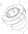
- an inner ring assembly 10 for a bearing 1 which preferably includes an outer ring 2 disposed about the inner ring 10 and a plurality of rolling elements 3 disposed between the inner ring assembly 10 and the outer ring 2 as shown in Fig. 2 .
- the bearing 1 rotatably couples a shaft 4 with an outer member 5, such as a housing, the shaft 4 being rotatable about a central axis Ac.
- the inner ring assembly 10 basically comprises a bearing annular body 12 disposeable about the shaft 4 and an annular locking collar 14 disposeable about a portion of the annular body 12 and configured to retain the body 12 radially and axially on the shaft 4. With such an integral mounting structure, the bearing inner ring assembly 10 is readily mountable upon the shaft 4 without requiring precision machining of the shaft outer surface 4a.
- the annular body 12 has a centerline 13, opposing first and second axial ends 12a, 12b, an inner circumferential surface 16 defining a central bore 17 for receiving the shaft 4 and an opposing outer circumferential surface 18.
- An annular groove 20 extends inwardly from the outer surface 18 and provides a bearing inner race 22 for receiving the rolling elements 3.
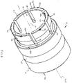
- a plurality of slotted openings 24 extend axially inwardly from the first axial end 12a of the annular body 12 and are spaced circumferentially about the centerline 13 so as to define a plurality of arcuate mounting tabs 26.
- Each mounting tab 26 has an inner end 26a integral with a remainder of the annular body 12 and an opposing, free outer end 26b at the body first axial end 12a.
- the annular locking collar 14 is disposed about the plurality of mounting tabs 26 and is configured to clamp the tabs 26 against the outer surface 4a of the shaft 4, as depicted in Figs. 2 and 3 . Such clamping of the mounting tabs 26 retains the inner ring annular body 12 radially and axially with respect to the shaft central axis Ac.
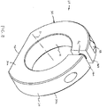
- the locking collar 14 preferably includes an annular body 30 having a centerline 31, first and second axial ends 30a, 30b, respectively, an inner circumferential surface 32 with an inside diameter IDc and an outer circumferential surface 34.
- the collar annular body 30 has a gap G C defining first and second spaced apart circumferential ends 36a, 36b, respectively, i.e., the gap G C extends both axially between the first and second axial ends 30a, 30b and radially between the inner and outer circumferential surfaces 32, 34 to form the circumferentially spaced or "circumferential" ends 36a, 36b.
- the annular body 30 has an inside diameter ID C in an unbended state, i.e., prior to clamping on the tabs 26, being sized such that the collar 14 is assembled about the plurality of mounting tabs 26 with a "line to line fit", as is well known in engineering tolerancing, for reasons discussed below.
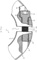
- a threaded rod 38 extends through the first and second circumferential ends 36a, 36b and the collar 14 is configured such that rotation of the rod "closes” the gap G C and clamps the collar 14 about the mounting tabs 26, i.e., with a clamping force F C ( Fig. 3 ).
- a threaded opening 40 is formed in the first circumferential end 36a and a through hole 42 is formed in the second circumferential end 36b, the opening 40 and the hole 42 being generally aligned and extending generally tangentially with respect to the collar centerline 31, as best shown in Fig. 10 .
- the threaded rod 38 extends through the through-hole 42 and into the threaded opening 40 and has a head 39 that bears against a shoulder surface 43 surrounding the hole 42.
- rotation of the rod 38 in a first angular direction A 1 Fig. 4
- Such reduction of the collar body inside diameter ID C causes the collar 14 to compress or clamp the plurality of mounting tabs 26 into engagement with the shaft 4, as indicated in Fig. 3 .
- threaded opening 40 and the through hole 42 are arranged such that torque applied to rotate the rod 38 in the first direction A 1 tends to bias a lower portion of the collar annular body 30 inwardly toward a center C B of the annular body 12 and against a lower portion of a radial stop surface 81 of the body 12, which facilitates installation of the inner ring assembly 10 on the shaft 4.
- the present inner ring assembly 10 has a number of improvements over previously known inner ring assemblies, such as follows.
- the locking ring assembly 10 is provided with at least one, and preferably two, structural features for retaining the locking collar 14 on the inner ring body 12 when the inner ring assembly 10 is separate from the shaft 4, i.e., during transport and prior to assembly.
- the locking collar 14 is formed so as to more evenly distribute the mass of the collar body 30 about the centerline 31 and thereby optimize dynamic balance of the inner ring assembly 10, and to also increase the clamping force exerted on the mounting tabs 26.
- the annular body 12 of the ring assembly 10 is formed to reduce stress concentration, particularly by improvements in the structure of the mounting tabs 26.
- the inner ring assembly 10 preferably has two structural features for retaining the locking collar 14 disposed about the inner ring body 30 when the inner ring assembly 10 is separate from the shaft 4, i.e., when the ring assembly 10 is in an unmounted or "dismounted” state.
- the mounting tabs 26 each has a projection 50 extending radially outwardly from the outer axial end 26b of each tab 26.
- Each projection 50 is disposeable against or engageable with the locking collar 14 to retain the collar 14 on the inner ring assembly 10.
- each retainer projection 50 is sized to permit the collar 14 to displace axially over the plurality of projections 50 during installation of the collar 14 on the inner ring body 12, unless the projections 50 are formed after installation of the collar 14 about the annular body 12, as discussed below. That is, each projection 50 has a limited radial height or extent such that, with slight inward bending of the mounting tabs 26 and angling or cocking of the collar body 30, the inner surface 32 of the collar 14 is able to pass over all of the projections 50 to become disposed about the plurality of mounting tabs 26.
- each projection 50 is also sized to engage with the first or outer axial end 30a of the collar annular body 30 to retain the locking collar 14 on the ring annular body 12.
- the projections 50 have a sufficient radial length/height to collectively retain the locking collar 14 from being axially displaced off of the mounting tabs 26 once installed thereabout.
- the radial height/length of each projection 50 is preferably lesser than the radial height of a chamfer 30e formed on the inner end 30b of the collar annular body 30 to enable the collar 14 to deflect the mounting tabs 26 radially inwardly during assembly of the collar 14.
- each projection 50 may be pre-formed as a forged or machined projection or may be formed after assembly of the collar 14 onto the mounting tabs 26, such as by staking or otherwise disrupting a portion of the material of each tab 26.
- each projection 50 is generally pyramidal-shaped and located generally centrally on each mounting tab outer end 26b, as best shown in Fig. 5 .
- each projection 50 may be provided by an arcuate radial lip 51 formed at the outer end 26a of each mounting tab 26, as depicted in Fig. 3 .
- the retainer projections 50 may have any other appropriate shape or the inner ring assembly 10 may be formed without any retainer projections, such that the locking collar 14 is retained solely by a movable retainer member 56, as follows.
- the inner ring assembly 10 may additionally or alternatively include a retainer member 56 movably coupled with and projecting radially inwardly from the locking collar 14.
- the retainer member 56 is engaged or engageable with one of the mounting tabs 26, preferably with a recess 58 of one of the mounting tabs 26, to thereby retain the locking collar 14 disposed about the ring annular body 12.
- each one of the mounting tabs 26 of the inner ring annular body 12 has an outer surface 27 with a recess 58, as described in detail below, and the retainer member 56 extends radially inwardly from the inner circumferential surface 32 of the collar body 30.
- the retainer member 56 has an inner radial end 56a disposeable within the recess 58 of one of the mounting tabs 26 to retain the locking collar 14 on the ring annular body 12.
- the locking collar 14 has a radial passage 60 with an opening 62 on the collar inner circumferential surface 32, which may be a blind hole 64, as shown in Fig. 11 , or a through hole 66 as depicted in Fig. 12 .
- the retainer member 56 is disposed within the passage 60 and extends through the passage opening 62.
- a spring 68 is disposed within the passage 60 and biases the retainer member 56 radially inwardly toward the one mounting tab 26, i.e., the mounting tab 26 which is located so as to extend beneath the passage 60.
- the retainer member 56 is preferably a sphere or "ball" 57 having a radially inner portion 57a disposed externally of the collar 14 and within the mounting tab recess 58.
- the spring 64 is compressed between the ball 57 and either an inner end 64a of the blind hole 64 or a threaded rod 67 enclosing the through hole 66.
- the retainer member 56 may be formed in any other appropriate manner, such as for example, as a stepped pin (not shown) slidably disposed within the passage 60.
- the locking collar 14 may alternatively be formed without any movable retainer member and may instead be retained on the inner ring body 12 solely by the projections 50 on the mounting tabs 26.
- the locking member 14 is preferably formed with the annular body 30 having an adjustable gap Gc, the threaded opening 40 and the through hole 42.
- a counterbore hole 44 is also formed adjacent to the through hole 42 and a partial "lead in" opening 46 is formed adjacent to the threaded opening 40 during drilling of the opening 40 prior to tapping the threads thereof.
- the gap Gc, the threaded opening 40 and the holes 42, 44, 46 each reduce the mass or weight of the collar body 30 in a section of the body 30 generally centered about the gap Gc, which is not compensated for by the mass of the threaded rod 38.
- the center of mass (not indicated) of the locking collar 14 is offset from the centerline 31 of the collar body 30, and therefore from the shaft central axis Ac.
- the inner ring assembly 10 is dynamically imbalanced during rotation of the shaft 4, which may result in vibration or excess stresses or strains within portions of the inner ring assembly 10.
- the annular body 30 of the locking collar 14 is preferably formed having a flat surface section 70 in the body outer circumferential surface 34.
- a flat surface section 70 is formed by removal of a circular segment from a solid annular body 30 and has a center C F and a length L F . between opposing ends 70a, 70b, as indicated in Fig. 9 .
- the center C F of the flat surface section 70 is spaced about one hundred eighty degrees (180°) from the collar gap Gc, so as to be located to offset the material losses or mass reduction in region of the gap Gc.
- the length L F of the flat surface 70 is selected so as to remove a sufficient amount of material from the annular body 30 to offset the material removed in the region of the gap G C so that the center of mass (not indicated) of the body 30 with the flat surface 70 is generally located on the centerline 31.
- the flat 70 functions to increase the dynamic balance the locking collar 14 about the shaft central axis Ac.
- the flexibility of the locking collar 14 is increased during compression of the mounting tabs 26.
- providing the flat surface section 70 forms two arcuate portions 30c, 30d of the collar annular body 30 which each extend between one end 70a, 70b, respectively, of the flat section 70 and a separate one of the circumferential ends 36a, 36b, respectively, of the body 30.
- each one of the slotted openings 24 in the annular body 12 is preferably partially bounded by a curved inner end surface 72, which are each adjacent to the bendable inner ends 26a of two mounting tabs 26.
- each slotted opening 24 is defined by facing first and second side surfaces 74, 76, each side surface 74, 76 extending axially inwardly from the annular body first axial end 12a, and the curved end surface 72 extends between and connects the inner ends 74a, 76a of the first and second side surfaces 74, 76.
- slotted openings typically have a "flat" end surface which extends perpendicular to the side surfaces and creates corners, which lead to a concentration of stress during bending of the adjacent tabs.
- the curved end surfaces 72 are partially circular as shown in Figs. 13 and 14 , and may extend circumferentially wider than the spacing between the side surfaces 74, 76, as depicted in Fig. 14 .
- each curved end surface 72 may have any other appropriate shape, such as partially elliptical, etc.
- each one of the mounting tabs 26 is preferably formed having an outer circumferential surface 27 with a radiused section 80 at the tab inner end 26a, a cylindrical section 82 extending axially inwardly from the tab outer end 26b and an angled section 84 extending between the radiused section 80 and the cylindrical section 82.
- the radiused section 80 and the angled section 82 define the tab recess 58 for receiving the collar retainer member 56, as described above, the recess 58 having an innermost point P I that is offset radially inwardly from the cylindrical section 84 by an offset distance do ( Fig. 16 ) as discussed below.
- the inner surface 32 of the locking collar 14 is disposed against and about the cylindrical surfaces 82 of all of the mounting tabs 26, with the second, inner end 30b of the collar body 30 preferably being disposed against a radial stop surface 81 of the annular body 12 formed radially outwardly of the recessed surface section 80, as shown in Fig. 3 .
- each mounting tab 26 is radially bendable at the radiused section 80 with respect to the remainder of the ring annular body 12 generally in the manner of a cantilever beam, thereby enabling the mounting tabs 26 to deflect inwardly during clamping by the locking collar 14.
- each tab cylindrical section 82 has an outside diameter OD T that is lesser than the outside diameter OD B of the remainder of the ring annular body 12, as shown in Fig. 16 .
- the radiused section 80 is preferably formed having a substantial radius R RS that extends between the remainder of the bearing annular body 12 and the angled section without any joints or disruptions which could concentrate stresses.
- the radius R RS is at least about half of the offset distance do of the recess 58, and most preferably about equal to the offset distance do, as depicted in Fig. 16 .
- the transition between the angled surface section 84 and the cylindrical surface section 82 eliminates a sharp edge or shoulder between the recess 58 and the tab surface 82 receiving clamping force F C from the locking collar 14. Therefore, with both the substantial radius R RS of the radiused section 80 and an angled surface section 84 which transitions to the cylindrical surface section 82 without any sharp edges, the stress concentrations within each mounting tab 26 are generally eliminated or at least significantly reduced.
Landscapes
- Engineering & Computer Science (AREA)
- General Engineering & Computer Science (AREA)
- Mechanical Engineering (AREA)
- Snaps, Bayonet Connections, Set Pins, And Snap Rings (AREA)
- Mounting Of Bearings Or Others (AREA)
- Rolling Contact Bearings (AREA)
Applications Claiming Priority (1)
| Application Number | Priority Date | Filing Date | Title |
|---|---|---|---|
| US17/479,477 US11536318B1 (en) | 2021-09-20 | 2021-09-20 | Bearing inner ring with integral mounting means |
Publications (2)
| Publication Number | Publication Date |
|---|---|
| EP4151875A2 true EP4151875A2 (de) | 2023-03-22 |
| EP4151875A3 EP4151875A3 (de) | 2023-06-07 |
Family
ID=83270960
Family Applications (1)
| Application Number | Title | Priority Date | Filing Date |
|---|---|---|---|
| EP22194550.4A Pending EP4151875A3 (de) | 2021-09-20 | 2022-09-08 | Verbesserter lagerinnenring mit integrierten montagemitteln |
Country Status (4)
| Country | Link |
|---|---|
| US (1) | US11536318B1 (de) |
| EP (1) | EP4151875A3 (de) |
| CN (1) | CN115839374A (de) |
| BR (1) | BR102022018274A2 (de) |
Families Citing this family (2)
| Publication number | Priority date | Publication date | Assignee | Title |
|---|---|---|---|---|
| US12025188B1 (en) * | 2021-10-01 | 2024-07-02 | Agility Robotics, Inc. | Actuator encoder assembly method and apparatus |
| JP2024155508A (ja) * | 2023-04-21 | 2024-10-31 | Ntn株式会社 | 軸受 |
Family Cites Families (11)
| Publication number | Priority date | Publication date | Assignee | Title |
|---|---|---|---|---|
| US3588208A (en) * | 1969-09-19 | 1971-06-28 | Tek Bearing Co | Locking device for antifriction bearing ring |
| US4537519A (en) * | 1984-09-14 | 1985-08-27 | Emerson Electric Co. | Shaft locking device for bearing assemblies |
| US4728202A (en) | 1987-01-14 | 1988-03-01 | Emerson Electric Co. | Shaft locking collar for bearing assemblies |
| US5417500A (en) | 1993-09-13 | 1995-05-23 | Reliance Electric Industrial Company | Bearing assembly utilizing improved clamping collar |
| US5863137A (en) * | 1997-02-07 | 1999-01-26 | Emerson Power Transmission Corp. | Shaft locking device for bearing assemblies |
| US6336748B2 (en) | 1999-01-22 | 2002-01-08 | Emerson Power Transmission Manufacturing, L.P. | Shaft locking device for bearing assemblies |
| USRE39027E1 (en) | 1997-02-07 | 2006-03-21 | Emerson Power Transmission Manufacturing, L.P. | Shaft locking device for bearing assemblies |
| US6840679B2 (en) * | 2002-03-05 | 2005-01-11 | Peer Bearing Company | Bearing assembly and locking collar |
| US7300210B2 (en) | 2004-01-08 | 2007-11-27 | Emerson Power Transmission Manufacturing, Llp | Bearing locking collar with laminated plates |
| US7306375B2 (en) * | 2005-11-02 | 2007-12-11 | Peer Bearing Company | Bearing locking collar retainer |
| IN2013MU03206A (de) | 2013-10-10 | 2015-07-03 | Emerson Power Transmission Corp |
-
2021
- 2021-09-20 US US17/479,477 patent/US11536318B1/en active Active
-
2022
- 2022-09-08 EP EP22194550.4A patent/EP4151875A3/de active Pending
- 2022-09-13 BR BR102022018274-4A patent/BR102022018274A2/pt unknown
- 2022-09-13 CN CN202211118921.9A patent/CN115839374A/zh active Pending
Also Published As
| Publication number | Publication date |
|---|---|
| US11536318B1 (en) | 2022-12-27 |
| EP4151875A3 (de) | 2023-06-07 |
| CN115839374A (zh) | 2023-03-24 |
| BR102022018274A2 (pt) | 2023-04-04 |
Similar Documents
| Publication | Publication Date | Title |
|---|---|---|
| EP4151875A2 (de) | Verbesserter lagerinnenring mit integrierten montagemitteln | |
| US8454242B2 (en) | Retention of ball bearing cartridge for turbomachinery | |
| US8317425B2 (en) | Mounting assembly | |
| US10094426B2 (en) | Tolerance ring with divided torque slip | |
| US7018104B2 (en) | Bearing assembly and method | |
| KR930010412B1 (ko) | 베어링 조립체 | |
| EP0010371A1 (de) | Turbineneinsatz und diesen enthaltendes zahnärztliches Handstück | |
| US6190260B1 (en) | Tripod universal joint and method of its manufacture | |
| US4195944A (en) | Frictional couplings | |
| EP0286883B1 (de) | Lagerung eines Abgasturboladers | |
| US20030137089A1 (en) | Adjustable disc spring systems and methods | |
| CA1067725A (en) | Variable speed pulley | |
| DE102020209287A1 (de) | Dichtungsanordnung mit großem Spiel | |
| KR880000812B1 (ko) | 축계수 | |
| US4540186A (en) | Anti-rotation device for contracting rod ring seals | |
| EP0362327A1 (de) | Axiallagerung mit einer schiefstellungskompensation. | |
| US11761541B2 (en) | Unitized seal assembly with axial positioner | |
| US20230366433A1 (en) | Radially-nested bearing assembly | |
| CN121039409A (zh) | 分体式调心滚子轴承 | |
| US11913494B2 (en) | Hub bearing assembly | |
| US20260078800A1 (en) | Thin section ball bearing | |
| JP4344630B2 (ja) | 等速ジョイント及びその組み付け方法 | |
| US6109898A (en) | Compressor ring attachment | |
| US11105377B2 (en) | Retaining ring assemblies | |
| US20030117007A1 (en) | Disc brake rotor mounting system |
Legal Events
| Date | Code | Title | Description |
|---|---|---|---|
| PUAI | Public reference made under article 153(3) epc to a published international application that has entered the european phase |
Free format text: ORIGINAL CODE: 0009012 |
|
| STAA | Information on the status of an ep patent application or granted ep patent |
Free format text: STATUS: THE APPLICATION HAS BEEN PUBLISHED |
|
| AK | Designated contracting states |
Kind code of ref document: A2 Designated state(s): AL AT BE BG CH CY CZ DE DK EE ES FI FR GB GR HR HU IE IS IT LI LT LU LV MC MK MT NL NO PL PT RO RS SE SI SK SM TR |
|
| PUAL | Search report despatched |
Free format text: ORIGINAL CODE: 0009013 |
|
| AK | Designated contracting states |
Kind code of ref document: A3 Designated state(s): AL AT BE BG CH CY CZ DE DK EE ES FI FR GB GR HR HU IE IS IT LI LT LU LV MC MK MT NL NO PL PT RO RS SE SI SK SM TR |
|
| RIC1 | Information provided on ipc code assigned before grant |
Ipc: F16C 19/06 20060101ALN20230501BHEP Ipc: F16C 35/063 20060101AFI20230501BHEP |
|
| STAA | Information on the status of an ep patent application or granted ep patent |
Free format text: STATUS: REQUEST FOR EXAMINATION WAS MADE |
|
| 17P | Request for examination filed |
Effective date: 20231204 |
|
| RBV | Designated contracting states (corrected) |
Designated state(s): AL AT BE BG CH CY CZ DE DK EE ES FI FR GB GR HR HU IE IS IT LI LT LU LV MC MK MT NL NO PL PT RO RS SE SI SK SM TR |
|
| STAA | Information on the status of an ep patent application or granted ep patent |
Free format text: STATUS: EXAMINATION IS IN PROGRESS |
|
| 17Q | First examination report despatched |
Effective date: 20250908 |
|
| RAP1 | Party data changed (applicant data changed or rights of an application transferred) |
Owner name: AKTIEBOLAGET SKF Owner name: SKF USA INC. |