EP4151863A1 - Fan motor and manufacturing method of the same - Google Patents
Fan motor and manufacturing method of the same Download PDFInfo
- Publication number
- EP4151863A1 EP4151863A1 EP22205688.9A EP22205688A EP4151863A1 EP 4151863 A1 EP4151863 A1 EP 4151863A1 EP 22205688 A EP22205688 A EP 22205688A EP 4151863 A1 EP4151863 A1 EP 4151863A1
- Authority
- EP
- European Patent Office
- Prior art keywords
- blade
- impeller
- coating layer
- area
- polymer
- Prior art date
- Legal status (The legal status is an assumption and is not a legal conclusion. Google has not performed a legal analysis and makes no representation as to the accuracy of the status listed.)
- Granted
Links
Images



Classifications
-
- H—ELECTRICITY
- H02—GENERATION; CONVERSION OR DISTRIBUTION OF ELECTRIC POWER
- H02K—DYNAMO-ELECTRIC MACHINES
- H02K7/00—Arrangements for handling mechanical energy structurally associated with dynamo-electric machines, e.g. structural association with mechanical driving motors or auxiliary dynamo-electric machines
- H02K7/14—Structural association with mechanical loads, e.g. with hand-held machine tools or fans
-
- F—MECHANICAL ENGINEERING; LIGHTING; HEATING; WEAPONS; BLASTING
- F04—POSITIVE - DISPLACEMENT MACHINES FOR LIQUIDS; PUMPS FOR LIQUIDS OR ELASTIC FLUIDS
- F04D—NON-POSITIVE-DISPLACEMENT PUMPS
- F04D29/00—Details, component parts, or accessories
- F04D29/40—Casings; Connections of working fluid
- F04D29/52—Casings; Connections of working fluid for axial pumps
- F04D29/522—Casings; Connections of working fluid for axial pumps especially adapted for elastic fluid pumps
- F04D29/526—Details of the casing section radially opposing blade tips
-
- F—MECHANICAL ENGINEERING; LIGHTING; HEATING; WEAPONS; BLASTING
- F04—POSITIVE - DISPLACEMENT MACHINES FOR LIQUIDS; PUMPS FOR LIQUIDS OR ELASTIC FLUIDS
- F04D—NON-POSITIVE-DISPLACEMENT PUMPS
- F04D29/00—Details, component parts, or accessories
- F04D29/40—Casings; Connections of working fluid
- F04D29/42—Casings; Connections of working fluid for radial or helico-centrifugal pumps
- F04D29/4206—Casings; Connections of working fluid for radial or helico-centrifugal pumps especially adapted for elastic fluid pumps
- F04D29/4226—Fan casings
-
- C—CHEMISTRY; METALLURGY
- C09—DYES; PAINTS; POLISHES; NATURAL RESINS; ADHESIVES; COMPOSITIONS NOT OTHERWISE PROVIDED FOR; APPLICATIONS OF MATERIALS NOT OTHERWISE PROVIDED FOR
- C09D—COATING COMPOSITIONS, e.g. PAINTS, VARNISHES OR LACQUERS; FILLING PASTES; CHEMICAL PAINT OR INK REMOVERS; INKS; CORRECTING FLUIDS; WOODSTAINS; PASTES OR SOLIDS FOR COLOURING OR PRINTING; USE OF MATERIALS THEREFOR
- C09D183/00—Coating compositions based on macromolecular compounds obtained by reactions forming in the main chain of the macromolecule a linkage containing silicon, with or without sulfur, nitrogen, oxygen, or carbon only; Coating compositions based on derivatives of such polymers
- C09D183/04—Polysiloxanes
-
- C—CHEMISTRY; METALLURGY
- C09—DYES; PAINTS; POLISHES; NATURAL RESINS; ADHESIVES; COMPOSITIONS NOT OTHERWISE PROVIDED FOR; APPLICATIONS OF MATERIALS NOT OTHERWISE PROVIDED FOR
- C09D—COATING COMPOSITIONS, e.g. PAINTS, VARNISHES OR LACQUERS; FILLING PASTES; CHEMICAL PAINT OR INK REMOVERS; INKS; CORRECTING FLUIDS; WOODSTAINS; PASTES OR SOLIDS FOR COLOURING OR PRINTING; USE OF MATERIALS THEREFOR
- C09D7/00—Features of coating compositions, not provided for in group C09D5/00; Processes for incorporating ingredients in coating compositions
- C09D7/40—Additives
- C09D7/60—Additives non-macromolecular
- C09D7/61—Additives non-macromolecular inorganic
-
- F—MECHANICAL ENGINEERING; LIGHTING; HEATING; WEAPONS; BLASTING
- F01—MACHINES OR ENGINES IN GENERAL; ENGINE PLANTS IN GENERAL; STEAM ENGINES
- F01D—NON-POSITIVE DISPLACEMENT MACHINES OR ENGINES, e.g. STEAM TURBINES
- F01D5/00—Blades; Blade-carrying members; Heating, heat-insulating, cooling or antivibration means on the blades or the members
- F01D5/12—Blades
- F01D5/28—Selecting particular materials; Particular measures relating thereto; Measures against erosion or corrosion
- F01D5/288—Protective coatings for blades
-
- F—MECHANICAL ENGINEERING; LIGHTING; HEATING; WEAPONS; BLASTING
- F04—POSITIVE - DISPLACEMENT MACHINES FOR LIQUIDS; PUMPS FOR LIQUIDS OR ELASTIC FLUIDS
- F04D—NON-POSITIVE-DISPLACEMENT PUMPS
- F04D29/00—Details, component parts, or accessories
- F04D29/02—Selection of particular materials
- F04D29/023—Selection of particular materials especially adapted for elastic fluid pumps
-
- F—MECHANICAL ENGINEERING; LIGHTING; HEATING; WEAPONS; BLASTING
- F04—POSITIVE - DISPLACEMENT MACHINES FOR LIQUIDS; PUMPS FOR LIQUIDS OR ELASTIC FLUIDS
- F04D—NON-POSITIVE-DISPLACEMENT PUMPS
- F04D29/00—Details, component parts, or accessories
- F04D29/08—Sealings
- F04D29/16—Sealings between pressure and suction sides
- F04D29/161—Sealings between pressure and suction sides especially adapted for elastic fluid pumps
- F04D29/162—Sealings between pressure and suction sides especially adapted for elastic fluid pumps of a centrifugal flow wheel
-
- F—MECHANICAL ENGINEERING; LIGHTING; HEATING; WEAPONS; BLASTING
- F04—POSITIVE - DISPLACEMENT MACHINES FOR LIQUIDS; PUMPS FOR LIQUIDS OR ELASTIC FLUIDS
- F04D—NON-POSITIVE-DISPLACEMENT PUMPS
- F04D29/00—Details, component parts, or accessories
- F04D29/18—Rotors
- F04D29/22—Rotors specially for centrifugal pumps
- F04D29/2205—Conventional flow pattern
- F04D29/2222—Construction and assembly
-
- F—MECHANICAL ENGINEERING; LIGHTING; HEATING; WEAPONS; BLASTING
- F04—POSITIVE - DISPLACEMENT MACHINES FOR LIQUIDS; PUMPS FOR LIQUIDS OR ELASTIC FLUIDS
- F04D—NON-POSITIVE-DISPLACEMENT PUMPS
- F04D29/00—Details, component parts, or accessories
- F04D29/60—Mounting; Assembling; Disassembling
- F04D29/62—Mounting; Assembling; Disassembling of radial or helico-centrifugal pumps
- F04D29/622—Adjusting the clearances between rotary and stationary parts
-
- F—MECHANICAL ENGINEERING; LIGHTING; HEATING; WEAPONS; BLASTING
- F04—POSITIVE - DISPLACEMENT MACHINES FOR LIQUIDS; PUMPS FOR LIQUIDS OR ELASTIC FLUIDS
- F04D—NON-POSITIVE-DISPLACEMENT PUMPS
- F04D29/00—Details, component parts, or accessories
- F04D29/66—Combating cavitation, whirls, noise, vibration or the like; Balancing
- F04D29/661—Combating cavitation, whirls, noise, vibration or the like; Balancing especially adapted for elastic fluid pumps
- F04D29/666—Combating cavitation, whirls, noise, vibration or the like; Balancing especially adapted for elastic fluid pumps by means of rotor construction or layout, e.g. unequal distribution of blades or vanes
-
- H—ELECTRICITY
- H02—GENERATION; CONVERSION OR DISTRIBUTION OF ELECTRIC POWER
- H02K—DYNAMO-ELECTRIC MACHINES
- H02K15/00—Processes or apparatus specially adapted for manufacturing, assembling, maintaining or repairing of dynamo-electric machines
-
- F—MECHANICAL ENGINEERING; LIGHTING; HEATING; WEAPONS; BLASTING
- F05—INDEXING SCHEMES RELATING TO ENGINES OR PUMPS IN VARIOUS SUBCLASSES OF CLASSES F01-F04
- F05D—INDEXING SCHEME FOR ASPECTS RELATING TO NON-POSITIVE-DISPLACEMENT MACHINES OR ENGINES, GAS-TURBINES OR JET-PROPULSION PLANTS
- F05D2230/00—Manufacture
- F05D2230/90—Coating; Surface treatment
-
- F—MECHANICAL ENGINEERING; LIGHTING; HEATING; WEAPONS; BLASTING
- F05—INDEXING SCHEMES RELATING TO ENGINES OR PUMPS IN VARIOUS SUBCLASSES OF CLASSES F01-F04
- F05D—INDEXING SCHEME FOR ASPECTS RELATING TO NON-POSITIVE-DISPLACEMENT MACHINES OR ENGINES, GAS-TURBINES OR JET-PROPULSION PLANTS
- F05D2300/00—Materials; Properties thereof
- F05D2300/20—Oxide or non-oxide ceramics
-
- F—MECHANICAL ENGINEERING; LIGHTING; HEATING; WEAPONS; BLASTING
- F05—INDEXING SCHEMES RELATING TO ENGINES OR PUMPS IN VARIOUS SUBCLASSES OF CLASSES F01-F04
- F05D—INDEXING SCHEME FOR ASPECTS RELATING TO NON-POSITIVE-DISPLACEMENT MACHINES OR ENGINES, GAS-TURBINES OR JET-PROPULSION PLANTS
- F05D2300/00—Materials; Properties thereof
- F05D2300/40—Organic materials
- F05D2300/43—Synthetic polymers, e.g. plastics; Rubber
-
- F—MECHANICAL ENGINEERING; LIGHTING; HEATING; WEAPONS; BLASTING
- F05—INDEXING SCHEMES RELATING TO ENGINES OR PUMPS IN VARIOUS SUBCLASSES OF CLASSES F01-F04
- F05D—INDEXING SCHEME FOR ASPECTS RELATING TO NON-POSITIVE-DISPLACEMENT MACHINES OR ENGINES, GAS-TURBINES OR JET-PROPULSION PLANTS
- F05D2300/00—Materials; Properties thereof
- F05D2300/40—Organic materials
- F05D2300/43—Synthetic polymers, e.g. plastics; Rubber
- F05D2300/436—Polyetherketones, e.g. PEEK
-
- F—MECHANICAL ENGINEERING; LIGHTING; HEATING; WEAPONS; BLASTING
- F05—INDEXING SCHEMES RELATING TO ENGINES OR PUMPS IN VARIOUS SUBCLASSES OF CLASSES F01-F04
- F05D—INDEXING SCHEME FOR ASPECTS RELATING TO NON-POSITIVE-DISPLACEMENT MACHINES OR ENGINES, GAS-TURBINES OR JET-PROPULSION PLANTS
- F05D2300/00—Materials; Properties thereof
- F05D2300/60—Properties or characteristics given to material by treatment or manufacturing
- F05D2300/611—Coating
Definitions
- the present invention relates to a fan motor and a manufacturing method the same and, more particularly, to a fan motor having an impeller cover surrounding the outer circumferential surface of an impeller, and a method of manufacturing the fan motor.
- a fan motor may be installed in home appliances such as a cleaner, an air conditioner, or a laundry machine, or vehicles and may generate airflow.
- a fan motor When a fan motor is installed in a home appliance such as a cleaner, it may generate a suction force that suctions air first into a dust collector.
- Such a fan motor may include a motor, an impeller connected to the motor, and an impeller cover surrounding the outer circumferential surface of the impeller.
- the impeller may be connected to a rotary shaft of the motor, so when the rotary shaft is rotated, the impeller can suction air into the impeller cover by rotating inside the impeller cover.
- the impeller may include a plurality of blades and may be mounted with a tip clearance between the blades and the inner circumferential surface of the impeller cover.
- Patent Document 1 KR 10-2013-0091841 A(published on August 20, 2013 )
- An object of the present invention is to provide a fan motor of which the efficiency can be increased by minimizing leakage flow between an impeller and a shroud, and a method of manufacturing the fan motor.
- a coating layer coated on the inner circumferential surface of a shroud includes a polymer and a bead having hardness higher than the polymer, so the coating layer can be more precisely ground by a blade of an impeller and leakage flow between the impeller and the shroud can be minimized.
- a fan motor may include: an impeller a hub connected to a rotary shaft and at least one blade formed on the outer surface of the hub; a shroud surrounding the outer circumference of the impeller; and a coating layer coated on the inner circumferential surface of the shroud.
- the coating layer may include: a polymer having hardness lower than the hardness of the blade; and a plurality of beads mixed with the polymer and having hardness higher than the hardness of the polymer.
- a portion of the coating layer may be ground by the blade, whereby a gap between the coating layer and the blade can be minimized.
- the coating layer may include: a first area having a first thickness; and a second area having a second thickness smaller than the first thickness and having a step from the first area, in which the blade may face the second area in the radial direction of the impeller.
- the blade includes a material having hardness higher than the polymer of the coating layer, thereby being able to minimize wear of the blade when the blade grinds the coating layer.
- the blade may include PEEK and the polymer may include silicon-based resin.
- the polymer may have hardness such that the coating layer is not severely worn and the blade grinding the coating layer is not worn.
- the polymer may have hardness of 30 Shore A to 50 Shore A.
- the bead mixed with the soft polymer may be hard, whereby the coating layer can be precisely ground.
- the bead may include ceramic.
- the bead may include an aluminum oxide.
- the mixing ratio of the bead included in the coating layer may be in the range where the adhesion of the coating layer to the inner wall of the shroud can be maintained.
- the bead may be included by 0.1wt% to 10wt% with respect to the coating layer of 100wt%.
- the bead may have a diameter in the range where the bead is uniformly mixed with the polymer and the coating layer can be precisely ground.
- the diameter of the bead may be 0.01mm to 0.1mm.
- a second thickness of a second area of the coating layer may change in the inner circumferential direction of the shroud. Accordingly, even if the rotational axis of the impeller is eccentric to the center axis of the shroud, leakage flow between the impeller and the shroud can be minimized.
- a fan motor may include: an impeller a hub connected to a rotary shaft and at least one blade formed on the outer surface of the hub; a shroud surrounding the outer circumference of the impeller; and a coating layer including a polymer and coated on the inner circumferential surface of the shroud.
- the coating layer may include: a first area having a first thickness; and a second area facing the impeller in the radial direction of the impeller and having at least a portion having a second thickness smaller than the first thickness. The second thickness may change in the inner circumferential direction of the shroud.
- the rotary shaft may be eccentric to a virtual axis of the shroud. Accordingly, the blade of the impeller can grind the coating layer such that the second thickness of the second area changes in the inner circumferential direction of the shroud.
- a gap between the blade and the second area may change in the circumferential direction of the impeller.
- the thickness of a portion of the second area may be the same as the first thickness.
- a method of manufacturing a fan motor includes forming a coating layer including a polymer and a bead mixed with the polymer on the inner circumferential surface of a shroud, and rotating the impeller while inserting the impeller in to the shroud, whereby a portion of the coating layer can be precisely ground by a blade of the impeller.
- a method of manufacturing a fan motor may include: manufacturing an impeller cover by forming a coating layer having a first thickness on the inner circumferential surface of a shroud; and rotating the impeller having a blade while inserting the impeller into the shroud, in which the coating layer may include: a polymer having hardness lower than the hardness of the blade; and a plurality of beads mixed with the polymer and having hardness higher than the hardness of the polymer, and when the impeller is rotated, the blade may grind a portion of the coating layer to have a second thickness smaller than the first thickness.
- the polymer when the impeller is rotated, the polymer may be ground along cracks connecting at least some of the plurality of beads. Accordingly, the coating layer can be more precisely ground by the blade.
- the blade includes a material having hardness higher than the polymer of the coating layer, thereby being able to minimize wear of the blade when the blade grinds the coating layer.
- the blade may include PEEK and the polymer may include silicon-based resin.
- the polymer may have hardness such that the coating layer is not severely worn and the blade grinding the coating layer is not worn.
- the polymer may have hardness of 30 Shore A to 50 Shore A.
- the bead mixed with the soft polymer may be hard, whereby the coating layer can be precisely ground.
- the bead may include ceramic.
- the bead may include an aluminum oxide.
- the mixing ratio of the bead included in the coating layer may be in the range where the adhesion of the coating layer to the inner wall of the shroud can be maintained.
- the coating layer may include the bead by 0.1wt% to 10wt%.
- the bead may have a diameter in the range where the bead is uniformly mixed with the polymer and the coating layer can be precisely ground.
- the diameter of the bead may be 0.01mm to 0.1mm.
- the coating layer can be precisely ground without being excessively cut off when the coating layer is ground by the blade. Accordingly, the gap between the ground surface of the coating layer and the blade can be minimized, and the leak flow that slides over a pressure-side surface to a suction-side surface of a blade is minimized, so a loss of channels is reduced and the efficiency of the fan motor is improved.
- the polymer is a silicon material and the bead is an alumina material, there is no peculiarity of materials, so coating is easy and accordingly cost reduction can be expected.
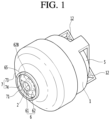
- FIG. 1 is a perspective view of fan motor according to an embodiment of the present invention
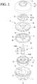
- FIG. 2 is an exploded perspective view of the fan motor according to an embodiment of the present invention
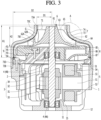
- FIG. 3 is a cross-sectional view showing the inside of the fan motor according to an embodiment of the present invention.
- a fan motor may include: a motor housing 1; a rotary shaft 2, a rotor 3 mounted on the rotary shaft 3; a stator 5 disposed inside the motor housing 1 and surrounding the rotor 3; an impeller 6 connected to the rotary shaft 2; and an impeller cover 7 surrounding the outer circumferential surface of the impeller 6.
- the impeller cover 7 may include a coating layer 74 for minimizing the gap between the impeller 6 and the impeller cover 7.
- a space S1 where the rotor 3 and the stator 5 are accommodated may be formed inside the motor housing 1.
- a bearing housing portion 11 for supporting a bearing 4 to be described below may be formed at the motor housing 1.
- An air outlet 12 through which air flowing in the space S1 by the impeller 6 is discharged to the outside may be formed at the motor housing 1.
- the rotor 3 and the bearing 4 may be mounted on the rotary shaft 2 and the rotary shaft 2 may constitute a rotary shaft assembly R together with the rotor 3 and the bearing 4.
- the rotary shaft 2 may be elongated into the impeller cover 7 from the inside of the motor housing 1. A portion of the rotary shaft 2 may be positioned inside the motor housing 1 and the other portion of the rotary shaft 2 may be positioned inside the impeller cover 7. The rotary shaft 2 may be positioned inside the motor housing 1 and inside the impeller cover 7.
- the rotary shaft 2, which rotates with the rotor 3, may be supported by the bearing 4.
- the rotary shaft 2 may be rotated by the rotor 3 while being rotated by the bearing 4.
- the impeller 6 may be connected to the rotary shaft 2, and when the rotary shaft 2 is rotated, the impeller 6 may be rotated inside the impeller cover 7.
- the rotor 3 may be mounted to surround a portion of the rotary shaft 2.
- the rotor 3 may be rotatably positioned in the stator 5.
- the rotor 3 may be formed in a hollow cylindrical shape.
- the rotor 3 may include a rotor core 31 fixed to the rotary shaft 2, a magnet 32 installed on the rotor core 31, and a pair of end plates 33 and 34 fixing the magnet 32.
- the rotor 3 may be mounted to surround a portion between an end and the other end of the rotary shaft 2.
- At least one bearing 4 may be installed on the rotary shaft 2.
- a pair of bearings 4A and 4B may be disposed on the rotary shaft 2.
- Any one 4A of the pair of bearings 4 may be supported by the bearing housing portion 11 formed at the motor housing 1.
- the other one 4B of the pair of bearings 4 may be supported by a bearing housing portion 91 formed at a motor bracket 9.
- the stator 5 may be mounted in the motor housing 1.
- the stator 5 may be mounted in the motor housing 1 and may be disposed in the motor housing 1 to surround the rotor 3.
- the stator 5 may be mounted in the motor housing 1 by fasteners such as screws.
- the stator 5 may be formed in a hollow cylindrical shape.
- the stator 3 may be mounted to surround the outer circumferential surface of the rotor 3.
- the stator 5 may be configured as an assembly of several members.
- the stator 5 may include a stator core 51, a pair of insulators 52 and 53 combined with the stator core 51; and coils 54 disposed at the insulators 52 and 53.
- the impeller 6 may be configured as a centrifugal impeller that axially suctions air and centrifugally blows the air and may be configured as a mixed-flow impeller that axially suctions air and blows the air diagonally between the axial direction and the centrifugal direction.
- the impeller 6 may include a hub 61 connected to the rotary shaft 2 and at least one blade 62 formed on the outer surface of the hub 61.
- the hub 61 may be connected to an end, which is positioned inside the impeller cover 7, of the rotary shaft 2.
- a hole in which the rotary shaft 2 is inserted may be formed at the center of the hub 61.
- the hub 61 may be formed in a shape of which the outer diameter gradually increases toward the rotor 3.
- the outer diameter of the end close to an air inlet 71 is the smallest and the outer diameter of the other end close to the rotor 3 may be may be the largest.
- the maximum outer diameter of the hub 61 may be the outer diameter of the end close to the rotor 3 of both ends of the hub 61.
- a plurality of blades 62 may be formed on the outer surface of the hub 61 and the plurality of blades 62 may be spaced apart from each other in the circumferential direction of the impeller 6.
- the blade may be formed in a curved plate shape and both sides thereof may include a pressure-side surface and a suction-side surface.
- the blade 62 may be formed in a 3D shape and may include a leading edge 63 at the foremost end in the airflow direction and a trailing edge 64 at the rearmost end in the airflow direction.
- the blade 62 may have a blade tip 65 positioned at the outermost side from the center axis of the hub 61.
- the blade tip 65 may be an outer tip positioned at the outermost side of the blade 62.
- the leading edge 63 and the trailing edge 64 may be connected to the blade tip 65.
- the blade tip 65 may connect the farthest tip from the hub 61 of the leading edge 63 and the farthest tip from the hub 61 of the trailing edge 64.
- the blade tip 65 may include an air inlet-facing area 65A (see FIG. 4 ) axially facing the air inlet 71 and a coating layer-facing area 65B (see FIG. 4 ) axially facing the coating layer 74.
- the entire blade tip 65 may radially face the coating layer 74.
- the tip clearance between the blade tip 65 and the impeller cover 7 is large, the amount of leakage flow is large, so it is preferable that the tip clearance is set such that leakage flow is minimized.
- the impeller cover 7 may include a coating layer 74 that can minimize the leakage flow.
- the coating layer 74 may be formed in advance at the shroud 73 before the fan motor is assembled, and a portion of the coating layer 74 may be ground off by the blade 62 of the impeller 6 when the fan motor is assembled.
- the air inlet 71 may be formed at the impeller cover 7. When the impeller 6 is rotated, the air outside the fan motor can be suctioned into the impeller cover 7 through the air inlet 71.
- the impeller cover 7 may include the shroud 73 surrounding the outer circumferential surface of the impeller 6 and the coating layer 74 coated on the inner circumferential surface of the shroud 73.
- the inner diameter of the shroud 73 may be increased in the airflow direction.
- the shroud 73 which guides air being suctioned to the impeller 6, may have a structure of which the inner radius D1 of an end 73A and the inner radius D2 of the other end 73B are different.
- the shroud 73 may be formed such that the inner radius D2 of the other end 73B is larger than the inner radius D2 of the end 73A.
- the shroud 73 may gradually increase in inner diameter from the end 73A to the other end 73B.
- the shroud 73 may be formed such that the entire area between the end 73A and the other end 73B gradually increases in inner diameter in the airflow direction. Further, the impeller 6 may be positioned inside the shroud 73 and the entire blade tip 65 may radially faces the shroud 73.
- the shroud 73 may include a small-diameter portion 73C, a large-diameter portion 73D, and an expanding portion 73E.
- the small-diameter portion 73C includes the end 73A of the shroud 73 and may be smaller in inner diameter than the large-diameter portion 73D.
- the air inlet 72 through which the air outside the fan motor flows into the shroud 73 may be formed in the small-diameter portion 73C.
- the large-diameter portion 73C includes the other end 73B of the shroud 73 and may be larger in inner diameter than the small-diameter portion 73C.
- the expanding portion 73E may connect the small-diameter portion 73C and the large-diameter portion 73D and may be formed such that the inner diameter gradually increases.
- the expanding portion 73E may be positioned between the small-diameter portion 73C and the large-diameter portion 73D in the airflow direction, air can flow into the expanding portion 73E through the inside the small-diameter portion 73C and can flow into the large-diameter portion 73D from the expanding portion 73E.
- the impeller 6 may be positioned inside the small-diameter portion 73C and inside the expanding portion 73E, some area of the blade tip 65 may radially face the small-diameter portion 73C, and the other area of the blade tip 65 may radially face the expanding portion 73E.
- the shroud 73 may include a large-diameter portion 73D and an expanding portion 73E without the small-diameter portion 73C.
- the expanding portion 73E may include the end 73A of the shroud 73, the air inlet 71 through which external air is suctioned into the fan motor may be formed at the expanding portion 73E, and the inner diameter of the expanding portion 73E may gradually increase toward the large-diameter portion 73D.
- the impeller 6 may be positioned inside the expanding portion 73E and the blade tip 65 may radially faces the expanding portion 73E.
- the shroud 73 may be formed integrally with the motor housing 1.
- the coating layer 74 may be formed on the inner circumferential surface of the shroud 73.
- the coating layer 74 is not ground through a separate grinding process and may be ground by the blade 62 when the fan motor is assembled. That is, a portion of the coating layer 74 may be cut off by the blade 62 when the fan motor is assembled.
- the coating layer 74 may be a kind of self-sacrifice coating.
- the coating layer 74 may include a soft polymer 74A having hardness lower than the hardness of the blade 62.
- the coating layer 74 is formed to be able to surround a portion of the leading edge 63, the entire of the blade tip 65, and a portion of the trailing edge 64.
- the height H1 of the coating layer 74 may be larger than the height H2 of the impeller 6.
- the height H1 of the coating layer 74 and the height H2 of the impeller 6 may be the axial length of the fan motor. Further, when the fan motor is assembled, the coating layer 74 may be disposed to surround the entire outer circumferential surface of the impeller 6.
- the coating layer 74 will be described in more detail later.
- the maximum outer diameter of the impeller 6 may be larger than the diameter of the air inlet 71.
- the maximum outer diameter of the impeller 6 may be larger than the minimum inner diameter of the small-diameter portion 73C and may be smaller than the maximum inner diameter of the expanding portion 73E.
- the maximum outer diameter of the impeller 6 may be the larger outer diameter of the maximum outer diameter of the hub 61 and the maximum outer diameter of the blade 62.
- the maximum outer diameter of the blade 62 may be double the maximum distance between the rotational center axis of the impeller 6 and the blade tip 65.
- the maximum distance between the center axis of the impeller 6 and the blade tip 65 of the blade 62 may be the maximum radius of the impeller 6 and the maximum radius of the impeller 6 may be larger than the radius of the air inlet 71.
- the fan motor may further include a diffuser 8 that guides air blown by the impeller 6.
- the air blown from the impeller 6 may be guided by the diffuser 8.
- the diffuser 8 may be disposed inside the impeller cover 7.
- the diffuser 8 may be mounted on at least one of the motor housing 1 and the motor bracket 9 to be described below.
- a gap through which air that is guided to the diffuser 8 can pass may be formed between the diffuser 8 and the impeller cover 7.
- the diffuser 8 may partially face the impeller 6 and a gap may be formed between a surface of the diffuser 8 and the diffuser-facing surface of the impeller 6.
- the diffuser 8 may have a hole 81 surrounding the outer circumferential surface of the bearing housing portion 9.
- the diffuser 8 may include a body part 85 being larger in size than the impeller cover 7 and positioned inside the impeller cover 7, and diffuser vanes 86 protruding from the outer circumferential surface of the body part 85.
- the body part 85 can guide air centrifugally blown from the impeller 6 to the inner circumferential surface of the impeller cover 7, between the impeller 6 and the stator 5, and the air that has passed through the outer circumferential surface of the body part 85 and the inner circumferential surface of the impeller cover 7 can be guided between the body part 85 and the stator 5.
- the diffuser vanes 86 may protrude from the body part 85 to be positioned between the outer circumferential surface of the body part 85 and the impeller cover 7.
- the diffuser vane 86 can convert the dynamic pressure of the air, which has passed through the impeller 6, into static pressure.
- the diffuser 8 may further include guide vanes 87 that guide air to the rotor 3 and the stator 5.
- the guide vanes 87 may be formed behind the diffuser vanes 86 in the airflow direction.
- the fan motor may further include the motor bracket 9 supporting the bearing 4.
- the motor bracket 9 may be combined with at least one of the motor housing 1 and the diffuser 8.
- the bearing housing portion 91 accommodating the bearing 4 may be formed at the motor bracket 9.
- a rotary shaft-through hole 92 through which the rotary shaft 2 passes may be formed at the bearing housing portion 91.
- the motor bracket 9 may be mounted in the motor housing 1.
- the motor bracket 9 may further include a fastening portion 94 fastened to the motor housing 1 by fasteners 93 such as screws.
- the motor bracket 9 may include at least one connecting portion 95 connecting the fastening portion 94 and the bearing housing portion 91.
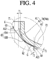
- FIG. 4 is a cross-sectional view enlarging the portion A shown in FIG. 3
- FIG. 5 is a view showing that a coating layer without a bead is ground by a blade
- FIG. 6 is a view showing that a coating layer according to an embodiment of the present invention is ground by a blade
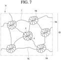
- FIG. 7 is a view illustrating in detail the portion that is ground by a blade in a coating layer.
- the coating layer 74 is not ground through a separate grinding process and may be ground by the blade 62 when the fan motor is assembled.
- the portion that is ground by the blade 62 of the coating layer 74 may include a portion being in contact with the blade 62.
- the blade 62 applies stress to the coating layer 74 in contact with the coating layer 74, the coating layer 74 is not accurately ground only at the portion being in contact with the blade 62, but may be ground even at a portion of the portion not being in contact with the blade 62. Accordingly, a fine gap may be formed between the blade 62 and the ground surface.
- the coating layer 74 may include a polymer 74a having hardness lower than the hardness of the blade 62 and a plurality of beads 74B mixed with the polymer 74A and having hardness higher than the polymer 74A.
- the polymer 74A may include soft polymer resin.
- the hardness of the polymer 74A may be lower than the hardness of the blade 62. Accordingly, the polymer 74A can be easily ground by the blade 62, and in this process, damage to the blade 62 can be minimized.
- the beads 74B may have hardness higher than the polymer 74A. That is, the polymer 74A may be soft and the beads 74B may be hard.
- the plurality of beads 74B may be mixed with the polymer 74A and uniformly distributed in the polymer 74A. Further, some of the plurality of beads 74B may be positioned on the surface of the polymer 74A.
- the plurality of beads 74B can prevent the coating layer 74 from being excessive cut off while the coating layer 74 is ground by the blade 62.
- a coating layer 74' without a bead may be composed of only a soft polymer 74A, as shown in FIG. 5 .
- stress of the blade 62 is transmitted into the soft polymer 74A, so crack may be generated in the polymer 74A. Since the cracks are randomly generated, a portion of the polymer 74A may be cut off in a lump, depending on the shape of the cracks.
- the gap k between the ground surface 74C' formed on the polymer 74A and the blade 62 may increase and the efficiency of the fan motor may be reduced due to leakage flow of the air flowing through the gap k.
- cracks C that are formed by stress of the blade 62 may be formed to connecting at least some of a plurality of beads 74B to each other. This is because the stress that is applied into the soft polymer 74A concentrates around the hard beads 74B.
- the cracks C formed in the polymer 74A of the coating layer 74 according to the present invention may be formed in accordance with a plurality of beads 74B and a portion GR of the polymer 74A may be separated along the cracks C.
- the polymer 74A can be cut off in a relative lump and the gap between the ground surface 74C and the blade 62 can be minimized. Accordingly, the coating layer 74 can be precisely cut.
- the coating layer 74 When the coating layer 74 is ground by the blade 62, some of a plurality of beads 74B may be positioned on the ground surface 74C of the polymer 74A.
- the beads 74B positioned on the ground surface 74C of the polymer 74A may be the beads 74B connected with the cracks C in the ground portion.
- the coating layer 74 may include a first area A1 having a first thickness T1 and a second area A2 having a second thickness T2 smaller than the first thickness T1 and having a step from the first area A1.
- the second area A2 may continue after the first area A1 in the airflow direction.
- the plurality of beads 74B may be uniformly distributed in the first area A1 and the second area A2.
- the coating layer 74 may further include a third area A3 having the first thickness T1 and continues after the second area A2.
- the plurality of beads may be uniformly distributed in the first area A1, the second area A2, and the third area A3.
- the coating layer 74 is formed to having a thickness that does not increase much the weight of the fan motor and considering the grinding depth by the blade 62 and the assembly tolerance of the impeller 6.
- the thickness of the coating layer 74 may mean the thickness of the polymer 74A.
- the coating layer 74 may have a uniform thickness in the airflow direction before the fan motor is assembled.
- the coating layer 74 may be formed with the first thickness on the inner circumferential surface of the shroud 73 before the fan motor is assembled.
- the first thickness T1 may be the same as or larger than the minimum distance between the inner circumferential surface of the shroud 73 and the blade 62.
- the minimum distance between the inner circumferential surface of the shroud 73 and the blade 62 may be 0.3mm and the first thickness T1 may be 0.3mm to 0.6mm.
- the coating layer 74 may not be ground by the blade 62, and when the first thickness T1 is larger than 0.6mm, the coating layer 74 may not be smoothly ground by the blade 62.
- the blade 62 When the impeller 6 is rotated, the blade 62 can come in contact with a portion of the coating layer 74. In this case, in the coating layer 74 a portion including the portion brought in contact with the blade 62 can be ground by the blade 62.
- the ground portion of the coating layer 74 can decrease in thickness from the first thickness T1 to the second thickness T2 and the non-ground portion can maintain the first thickness T1.
- the portion not ground by the blade 62 of the coating layer 74 may be the first area A1 and the third area A3 and the remaining portion after a portion of the coating layer 74 is ground by the blade 62 may be the second area A2.
- the second area A2 may include the ground surface 74C.
- the surface of the second area A2 may be the ground surface 74C. Accordingly, some of the plurality of beads 74B included in the coating layer 74 may be positioned on the surface of the second area A2.
- the second thickness T2 of the second area A2 may be uniform or changed in the airflow direction.
- the thickness of the thickest portion of the second area A2 may be smaller than the first thickness T1 of each of the first area A1 and the third area A3. Further, when the second thickness T2 of the second area A2 is changed in the airflow direction, the average thickness of the second area A2 may be smaller than the first thickness T1 of each of the first area A1 and the third area A3.
- first thickness T1 of the first area A1 may be uniform or changed in the airflow direction. Further, the first thickness T1 of the third area A3 may be uniform or changed in the airflow direction.
- the thickness of the thickest portion of the second area A2 may be smaller than the average thickness of the first area A1 and the average thickness of the third area A3.
- the average thickness of the second area A2 may be smaller than the average thickness of the first area A and the average thickness of the third area A3.
- the number of the beads 74B positioned in the second area A2 may be smaller than the number of the beads 74B positioned in the first area A1 or the third area A3, depending on the thickness differences of the areas A1, A2, and A3.
- the number of the beads 74B may mean the number of beads included in a cross-section cut in the thickness direction of each of the areas A1, A2, and A3.
- the blade 62 of the impeller 6 may radially face the small-diameter portion 73C (see FIG. 3 ) and the expanding portion 73E (see FIG. 3 ) of the shroud 73, and a portion of the portion coated on the inner circumferential surface of the small-diameter portion 73C and a portion of the portion coated on the inner circumferential surface of the expanding portion 73E of the coating layer 74 may be ground by the blade 62.
- the first area A1 and the third area A3 that are non-ground portions may be positioned with the second area A2 that is a ground portion therebetween. Further, the blade 62 of the impeller 6 may radially face the second area A2.
- the second area A2 may be formed on the inner surface of the small-diameter portion 73C and the inner surface of the expanding portion 73E or on the inner surface of the expanding portion 73E.
- the second area A2 may be formed on a portion of the inner surface of the small-diameter portion 73C and may be formed on a portion or the entire of the inner surface of the expanding portion 73E.
- the second area A2 may be formed in the inner surface of the expanding portion 73E.
- the second area A2 may be formed on a portion of the inner surface of the expanding portion 73E.
- the blade 62 may be made of a nonmetallic material.
- the blade 62 may include polyether ehter ketone (hereafter, referred to as PEEK).
- the blade 62 may be formed integrally with the hub 61 by injection molding, and in this case, the entire impeller 6 may be made of a nonmetallic material, particularly, PEEK.
- PEEK which is engineering plastic developed by ICI in U.K., is engineering plastic having excellent heat resistance, hardness, and flameproof ability.
- the blade 62 may include PEEK 1000, PEEK HPV, PEEK GF30, PEEK CA30, etc., and may have tensile strength of 100MPa, elongation of 55%, and compression strength of 128Mpa.
- the polymer 74A may be lower in hardness than the impeller 6 that is made of a nonmetallic material, particularly, the blade 62, and can be ground by the blade 62.
- the polymer 74A is made of a soft material having hardness of 80% or less of the hardness of the blade 62.
- the polymer 74A may be synthetic resin.
- the polymer 74A may be a material having low bending hardness.
- the polymer 74A may include silicon having hardness lower than that of PEEK.
- the polymer 74A may include Polydimethylsiloxane (PDMS).
- PDMS Polydimethylsiloxane
- the silicon has a meaning including silicon compounds.
- the Shore hardness of the polymer 74A may be 30 to 50.
- the polymer 74A may include silicon-based resin having Shore hardness of 30 Shore A to 50 Shore A.
- the polymer 74A When the hardness of the polymer 74A is less than Shore 30A, the polymer 74A is severely worn, so the gap between the coating layer 74 and the blade 62 may increase and the efficiency of the fan motor may be deteriorated. Further, when the hardness of the polymer 74A exceeds Shore 50A, grinding by the blade 62 may not be smoothly performed or the blade 62 may be worn. Accordingly, it is preferable that the polymer 74A has hardness of 30 Shore A to 50 Shore A.
- the hardness is not limited thereto and the polymer 74A may include Teflon having hardness lower than PEEK.
- the polymer 74A may include polytetra fluoro ethylene (PTFE) or ethylene tetrafluoroethylene (hereafter, referred to as ETFE).
- the beads 74B may be higher in hardness than the polymer 74A and may concentrate stress that is transmitted into the polymer 74B by the blade 62, thereby forming cracks C in the polymer 74B.
- the bead 74B may be hard and the polymer 74A may be soft.
- the beads 74B may include at least one of metal and ceramic.
- the beads 74B may be metal powder or ceramic powder.
- the beads 74B may include an aluminum oxide that is a kind of ceramic.
- the diameter of the beads 74B may be smaller than the length corresponding to the thickness of the polymer 74A.
- the diameter of the beads 74B may be smaller than the length corresponding to the second thickness T2 of the polymer 74A.
- the diameter of the beads 74B may mean the diameter d of a circumscribed circle R of the beads 74B.
- the diameter of the beads 74B may be 0.01mm to 0.1mm. When the diameter of the beads 74B is less than 0.01mm, the cohesion between the plurality of beads 74B excessively increases, so they may not be uniformly distributed and the manufacturing cost of the beads 74B may increase.
- the coating layer 74 may be excessively cut off by grinding by the blade 62.
- the diameter of the beads 74B is larger than 0.11, the forming density of the cracks C may be relatively reduced in comparison to when the diameter of the beads 74B is 0.1mm or less. That is, the cracks C may be relatively sparsely formed and a portion of the polymer 74A may be cut off in a large lump by the shape of the cracks C.
- the coating layer 74 is ground, the beads 74B may be cut off the polymer 74A and grooves may be formed on the polymer 74A by cutting-off of the beads 74B. In this case, when the diameter of the beads 74B is larger than 0.1mm, the sizes of the grooves are also large, so the gap between the grooves and the blade 62 may be increased.
- the beads 74B are included in the coating layer 74 with weight density such that the blade 62 is not damaged and the polymer 74A can be precisely ground.
- the coating layer 74 may include beads 74B of 0.01wt% to 10wt%.
- the coating layer 74 may include beads 74B of 3wt% to 10wt%.
- the coating layer 74 includes beads 74B less than 3wt%, the distribution density of the beads 74B is low, so the distances between the beads 74B may increase and cracks C may not be smoothly formed.
- the coating layer 74 includes beads 74B more than 10wt%, the adhesion of the polymer 74A decreases, so the coating layer 74 may not be smoothly bonded to the inner circumferential surface of the shroud 73 or may be separated from the inner circumferential surface.
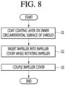
- FIG. 8 is a flowchart showing a method of manufacturing a fan motor according to an embodiment of the present invention and FIG. 9 is a side view before the fan motor according to an embodiment of the present invention is assembled.
- a method of manufacturing a fan motor of the present embodiment may include an impeller cover manufacturing step (S1), an impeller rotating step (S2), and an impeller cover combining step (S3).
- the impeller cover manufacturing step (S1) may be a step of manufacturing the impeller cover 7 by forming the coating layer 74 having the first thickness T1 on the inner circumferential surface of the shroud 73 of which the inner diameter increases in an airflow direction.
- the impeller cover manufacturing step (S1) may be formed in a preparation process before the fan motor is assembled and the impeller cover 7 may be provided to the assembly line of the fan motor with the coating layer with the first thickness T1 formed on the inner circumferential surface of the shroud 73.
- the polymer 74A of the coating layer may be a soft material having hardness lower than the hardness of the blade 62 and the beads 74B may be a hard material having hardness higher than the polymer 74A.
- the blade 62 of the impeller 6 that is rotated in the impeller rotating step (S2) may be made of PEEK.
- the polymer 94A of the coating layer 74 that is coated in the impeller cover manufacturing step (S1) may be synthetic resin such as silicon and the beads 74B may be metal such as alumina.
- the coating layer 74 may be formed coating the polymer 74A mixed with the beads 74B on the inner circumferential surface of the shroud 73.
- the coating layer 74 may be formed on the inner circumferential surface of the shroud 73 by spray coating.
- the coating method of the coating layer 74 is not limited thereto.
- the coating layer may be formed on the inner circumferential surface of the shroud 73 by electrostatic painting.
- the detailed coating process of the coating layer 74 may include a process of adding and mixing the polymer 74A and the beads 74B, a process of repeatedly spray-coating the polymer 74A mixed with the beads 74B to the inner circumferential surface of the shroud 73, and a process of firing the polymer 73A coated on the inner circumferential surface of the shroud 73.
- the coating layer 74 may be formed with a uniform first thickness T1 throughout the inner circumferential surface of the shroud 73.
- the impeller rotating step (S2) may be a step rotating the impeller 6 having the blade 62 on the hub 61 while inserting the impeller 6 into the impeller cover 7, as shown in FIG. 9 .
- the impeller 6 When the impeller 6 is inserted and rotated, the impeller 6 can be forcibly fitted into the impeller cover 7 with the impeller 6 and the shroud 73 aligned with concentric axis O, and the blade tip 65 of the blade 62 can grind a portion of the coating layer 74 into the second thickness T2 smaller than the first thickness T1 by rubbing on a portion of the coating layer 74.
- the polymer 74A of the coating layer 74 can be ground along cracks C formed to connect at least some of a plurality of beads 74B and the coating layer 74 can be very precisely machined such that the gap between the ground surface 74C of the polymer 74A and the blade 62 of the impeller 6 is small.
- the coating layer 74 may include the first area A1 and the third area A3 not ground by the blade 62 and a second area A1 ground by the blade 62, and the blade 62 may radially face the second area A1. In more detail, the blade 62 may radially face the surface of the second area A2 that is the ground surface.
- the second area A2 may be an area recessed with a thickness smaller than the thickness of the first area A1 and the third area A3, and an end thereof may be stepped from the first area A1 in the airflow direction and the other end may be stepped from the third area A3 in the airflow direction.
- the interface A12 of the first area A1 and the second area A2, in the first area A1 may axially cover the outer tip of the leading edge 63.
- the outer tip of the leading edge 63 may the farthest tip fro the hub 61 of the leading edge 63.
- the interface A23 between the second area A2 and the third area A3, in the third area A3, may radially cover the outer tip of the trailing edge 64.
- the trailing edge 64 may be the farthest tip from the hub 61.
- a blade tip accommodating groove G in which at least a portion of the blade tip 65 is accommodated may be formed between the interface A12 of the first area A1 and the second area A2 and the interface A23 of the second area A2 and the third area A3.
- the coating layer 74 having the second thickness T2 remains between the blade tip 65 of the blade 62 and the inner circumferential surface of the shroud 73, and a minimum gap is formed between the blade tip 65 and the coating layer 74.
- the impeller cover combining step (S3) may be a step of coupling the impeller cover 7 to the motor housing 1.
- the impeller cover 7 may be fastened to the motor housing 1 with the gap formed by an adhesive member such as an adhesive or a fastener such as a screw, and the gap between the impeller 6 and the impeller cover 7 may be maintained without expanding.
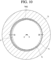
- FIG. 10 is a cross-sectional view showing a second area of a coating layer of a fan motor according to another embodiment of the present invention.
- the rotary shaft 3 may be eccentrically disposed with respect to the center axis O of the shroud 73.
- the center axis P of the rotary shaft 3 and the center axis O of the shroud 73 may be eccentric without meeting.
- the center axis P of the rotary shaft 3 and the center axis O of the shroud 73 may be virtual axes.
- the center axis P of the rotary shaft 3 may mean the center axis of the impeller 6 and the impeller 6 and the shroud 73 may not be concentric.
- the second area A2 of the coating layer 74 may be non-uniformly ground in the inner circumferential direction of the shroud 73. That is, a portion of the second area A2 may be ground relatively deep and the other portion of the second area A2 may be ground relatively thin. That is, the second thickness T2 of the second area A2 may be changed in the inner circumferential direction of the shroud 73. The second thickness T2 may change from the maximum thickness t2a to the minimum thickness t2b in the inner circumferential direction of the shroud 73.
- the impeller 6 and the shroud 73 may become eccentric to each other due to vibration etc. by long-time use of the fan motor.
- the blade tip 65 of the blade 62 Before eccentricity is generated between the center axis P of the impeller 6 and the center axis O of the shroud 73, the blade tip 65 of the blade 62 can rotate along a first virtual path Ri and grind the second area A2. Thereafter, when eccentricity is generated between the center axis P of the impeller 6 and the center axis O of the shroud 73, the blade tip 65 of the blade 62 can rotate along a second virtual path Rf and additionally grind a portion of the second area A2.
- the maximum thickness t2a of the second thickness T2 of the second area A2 may be the same as the thickness of the second area A2 grounded by the blade 62 before eccentricity is generated between the center axis P of the impeller 6 and the center axis O of the shroud 73. Further, the second thickness T2 of the second area A2 may be formed at the portion where the center axis P of the impeller 6 is eccentric to the center axis O of the shroud 73 and the second area A2 is additionally ground.
- a gap K may be formed between the blade 62 and the second area A2.
- the gap K may be formed between a portion of the inner circumference of the second area A2 and the blade tip 65.
- the gap K may change in the circumferential direction of the impeller 6.
- the gap K may be formed between the area having the maximum thickness t2a of the second thickness T2 of the second area A2 and the second movement path Rf.
- the rotary shaft 3 of the impeller 6 may be forcibly inserted eccentrically to the center axis O of the shroud 73 when the fan motor is assembled.
- the blade tip 65 of the blade 62 can rotate along the second virtual path Rf and can grind at least a portion of the second area A2.
- At least a portion of the second area A2 facing the impeller 6 in the radial direction of the impeller 6 may have the second thickness T2 smaller than the first thickness T1. That is, at least a portion of the second area T2 can be ground to have the second thickness T2 by the blade 62 of the impeller 6 of which the blade tip 65 rotates along the second virtual path Rf.
- the thickness of a portion of the second area A2 may be the same as the first thickness that is the thickness of the first area A1. That is, the maximum thickness t2a of the thickness of the second area A2 may be the same as the first thickness T1. This is because the blade 62 of the impeller 6 being eccentric to the shroud 73 does not grind a portion of the second area A2.
- the gap K formed between the blade 62 and the second area A2 can be changed in the circumferential direction of the impeller 6 and may be formed between the area having the same thickness as the first thickness T1 of the second thickness T2 of the second area A2 and the second movement path Rf.
- the invention is further defined by the following items.
Landscapes
- Engineering & Computer Science (AREA)
- Mechanical Engineering (AREA)
- General Engineering & Computer Science (AREA)
- Chemical & Material Sciences (AREA)
- Materials Engineering (AREA)
- Power Engineering (AREA)
- Life Sciences & Earth Sciences (AREA)
- Wood Science & Technology (AREA)
- Organic Chemistry (AREA)
- Manufacturing & Machinery (AREA)
- Chemical Kinetics & Catalysis (AREA)
- Inorganic Chemistry (AREA)
- Structures Of Non-Positive Displacement Pumps (AREA)
- Ceramic Engineering (AREA)
Abstract
Description
- The present invention relates to a fan motor and a manufacturing method the same and, more particularly, to a fan motor having an impeller cover surrounding the outer circumferential surface of an impeller, and a method of manufacturing the fan motor.
- A fan motor may be installed in home appliances such as a cleaner, an air conditioner, or a laundry machine, or vehicles and may generate airflow.
- When a fan motor is installed in a home appliance such as a cleaner, it may generate a suction force that suctions air first into a dust collector.
- Such a fan motor, for example, may include a motor, an impeller connected to the motor, and an impeller cover surrounding the outer circumferential surface of the impeller.
- The impeller may be connected to a rotary shaft of the motor, so when the rotary shaft is rotated, the impeller can suction air into the impeller cover by rotating inside the impeller cover.
- The impeller may include a plurality of blades and may be mounted with a tip clearance between the blades and the inner circumferential surface of the impeller cover.
- When the tip clearance is too small, the blades or the impeller cover may wear, but when it is too large, excessive leakage flow slides over the tips of the blades, so the efficiency of the fan motor may be deteriorated.
- (Patent Document 1)
KR 10-2013-0091841 A(published on August 20, 2013 - An object of the present invention is to provide a fan motor of which the efficiency can be increased by minimizing leakage flow between an impeller and a shroud, and a method of manufacturing the fan motor.
- In a fan motor according to an embodiment of the present invention, a coating layer coated on the inner circumferential surface of a shroud includes a polymer and a bead having hardness higher than the polymer, so the coating layer can be more precisely ground by a blade of an impeller and leakage flow between the impeller and the shroud can be minimized.
- In more detail, a fan motor according to an embodiment of the present invention may include: an impeller a hub connected to a rotary shaft and at least one blade formed on the outer surface of the hub; a shroud surrounding the outer circumference of the impeller; and a coating layer coated on the inner circumferential surface of the shroud. The coating layer may include: a polymer having hardness lower than the hardness of the blade; and a plurality of beads mixed with the polymer and having hardness higher than the hardness of the polymer.
- A portion of the coating layer may be ground by the blade, whereby a gap between the coating layer and the blade can be minimized. In more detail, the coating layer may include: a first area having a first thickness; and a second area having a second thickness smaller than the first thickness and having a step from the first area, in which the blade may face the second area in the radial direction of the impeller.
- The blade includes a material having hardness higher than the polymer of the coating layer, thereby being able to minimize wear of the blade when the blade grinds the coating layer. In more detail, the blade may include PEEK and the polymer may include silicon-based resin.
- The polymer may have hardness such that the coating layer is not severely worn and the blade grinding the coating layer is not worn. In more detail, the polymer may have hardness of 30 Shore A to 50 Shore A.
- The bead mixed with the soft polymer may be hard, whereby the coating layer can be precisely ground. In more detail, the bead may include ceramic. In more detail, the bead may include an aluminum oxide.
- The mixing ratio of the bead included in the coating layer may be in the range where the adhesion of the coating layer to the inner wall of the shroud can be maintained. In more detail, the bead may be included by 0.1wt% to 10wt% with respect to the coating layer of 100wt%.
- The bead may have a diameter in the range where the bead is uniformly mixed with the polymer and the coating layer can be precisely ground. In more detail, the diameter of the bead may be 0.01mm to 0.1mm.
- In the fan motor according to an embodiment of the present invention, a second thickness of a second area of the coating layer may change in the inner circumferential direction of the shroud. Accordingly, even if the rotational axis of the impeller is eccentric to the center axis of the shroud, leakage flow between the impeller and the shroud can be minimized.
- In more detail, a fan motor according to an embodiment of the present invention may include: an impeller a hub connected to a rotary shaft and at least one blade formed on the outer surface of the hub; a shroud surrounding the outer circumference of the impeller; and a coating layer including a polymer and coated on the inner circumferential surface of the shroud. The coating layer may include: a first area having a first thickness; and a second area facing the impeller in the radial direction of the impeller and having at least a portion having a second thickness smaller than the first thickness. The second thickness may change in the inner circumferential direction of the shroud.
- Further, the rotary shaft may be eccentric to a virtual axis of the shroud. Accordingly, the blade of the impeller can grind the coating layer such that the second thickness of the second area changes in the inner circumferential direction of the shroud.
- A gap between the blade and the second area may change in the circumferential direction of the impeller.
- The thickness of a portion of the second area may be the same as the first thickness.
- On the other hand, a method of manufacturing a fan motor according to an embodiment of the present embodiment includes forming a coating layer including a polymer and a bead mixed with the polymer on the inner circumferential surface of a shroud, and rotating the impeller while inserting the impeller in to the shroud, whereby a portion of the coating layer can be precisely ground by a blade of the impeller.
- In more detail, a method of manufacturing a fan motor according to an embodiment of the present invention may include: manufacturing an impeller cover by forming a coating layer having a first thickness on the inner circumferential surface of a shroud; and rotating the impeller having a blade while inserting the impeller into the shroud, in which the coating layer may include: a polymer having hardness lower than the hardness of the blade; and a plurality of beads mixed with the polymer and having hardness higher than the hardness of the polymer, and when the impeller is rotated, the blade may grind a portion of the coating layer to have a second thickness smaller than the first thickness.
- Further, when the impeller is rotated, the polymer may be ground along cracks connecting at least some of the plurality of beads. Accordingly, the coating layer can be more precisely ground by the blade.
- Further, the blade includes a material having hardness higher than the polymer of the coating layer, thereby being able to minimize wear of the blade when the blade grinds the coating layer. In more detail, the blade may include PEEK and the polymer may include silicon-based resin.
- The polymer may have hardness such that the coating layer is not severely worn and the blade grinding the coating layer is not worn. In more detail, the polymer may have hardness of 30 Shore A to 50 Shore A.
- The bead mixed with the soft polymer may be hard, whereby the coating layer can be precisely ground. In more detail, the bead may include ceramic. In more detail, the bead may include an aluminum oxide.
- The mixing ratio of the bead included in the coating layer may be in the range where the adhesion of the coating layer to the inner wall of the shroud can be maintained. In more detail, the coating layer may include the bead by 0.1wt% to 10wt%.
- The bead may have a diameter in the range where the bead is uniformly mixed with the polymer and the coating layer can be precisely ground. In more detail, the diameter of the bead may be 0.01mm to 0.1mm.
- According to a preferred embodiment of the present invention, there is the advantage that it is possible to reduce a loss of channels and improve the efficiency of a fan motor by minimizing leak flow that slides over a pressure-side surface to a suction-side surface of a blade.
- Further, there is the advantage that even if there is an injection-molding error of a blade and an assembly tolerance of the fan motor, the error or tolerance can be compensated in accordance with the ground depth of the coating layer and the reliability of maintaining a minimum air cap is high.
- Further, there is the advantage that even if the propulsion of the impeller increases and the impeller comes close to the coating layer while the fan motor is used, a portion of the remaining coating layer is grounded, thereby being cope with the increase of the propulsion.
- Further, there is the advantage that since the bead is included in the coating layer, the coating layer can be precisely ground without being excessively cut off when the coating layer is ground by the blade. Accordingly, the gap between the ground surface of the coating layer and the blade can be minimized, and the leak flow that slides over a pressure-side surface to a suction-side surface of a blade is minimized, so a loss of channels is reduced and the efficiency of the fan motor is improved.
- Further, there is the advantage that since the polymer of the coating layer has hardness lower than the blade, the blade is not worn.
- Further, there is the advantage that since the polymer of the coating layer is soft, the polymer is smoothly ground even if the output of the fan motor is slightly low.
- Further, there is the advantage that since the polymer is a silicon material and the bead is an alumina material, there is no peculiarity of materials, so coating is easy and accordingly cost reduction can be expected.
- Further, there is the advantage that since the hard bead is mixed with the soft polymer in the coating layer, stress that is transmitted into the polymer by the blade can concentrate around the bead and cracks connecting the beads can be formed in the polymer. Accordingly, a portion of the polymer can be cut off along the cracks and excessive cutting-off of the polymer is prevented.
- Further, there is the advantage that since there is the coating layer between the blade and the inner circumferential surface of the shroud, the concern of damage to the inner circumferential surface of the shroud due to contact with the blade is prevented.
- Further, there is the advantage that since the impeller is inserted in the shroud and grinds the coating layer, the manufacturing cost of the fan motor is reduced in comparison to a manufacturing method of precisely machining a coating layer and then inserting an impeller into a shroud.
- Further, there is the advantage that since the second thickness of the second area changes in the inner circumferential direction of the shroud, the gap between the blade and the inner circumference of the blade can be minimized even if the rotational axis of the impeller is eccentric to the virtual center axis of the shroud.
- The above and other objects, features and other advantages of the present invention will be more clearly understood from the following detailed description when taken in conjunction with the accompanying drawings, in which:
-
FIG. 1 is a perspective view of a fan motor according to an embodiment of the present invention; -
FIG. 2 is an exploded perspective view of the fan motor according to an embodiment of the present invention; -
FIG. 3 is a cross-sectional view showing the inside of the fan motor according to an embodiment of the present invention; -
FIG. 4 is a cross-sectional view enlarging the portion A shown inFIG. 3 ; -
FIG. 5 is a view showing that a coating layer without a bead is ground by a blade; -
FIG. 6 is a view showing that a coating layer according to an embodiment of the present invention is ground by a blade; -
FIG. 7 is a view illustrating in detail the portion that is ground by a blade in a coating layer; -
FIG. 8 is a flowchart showing a method of manufacturing a fan motor according to an embodiment of the present invention; -
FIG. 9 is a side view before the fan motor according to an embodiment of the present invention is assembled; and -
FIG. 10 is a cross-sectional view showing a second area of a coating layer of a fan motor according to another embodiment of the present invention. - Exemplary embodiments of the present inveniton will be described in detail hereafter with reference to the accompanying drawings.
-
FIG. 1 is a perspective view of fan motor according to an embodiment of the present invention,FIG. 2 is an exploded perspective view of the fan motor according to an embodiment of the present invention, andFIG. 3 is a cross-sectional view showing the inside of the fan motor according to an embodiment of the present invention. - A fan motor according to the present embodiment may include: a
motor housing 1; arotary shaft 2, arotor 3 mounted on therotary shaft 3; astator 5 disposed inside themotor housing 1 and surrounding therotor 3; animpeller 6 connected to therotary shaft 2; and animpeller cover 7 surrounding the outer circumferential surface of theimpeller 6. Theimpeller cover 7 may include acoating layer 74 for minimizing the gap between theimpeller 6 and theimpeller cover 7. - A space S1 where the
rotor 3 and thestator 5 are accommodated may be formed inside themotor housing 1. - A bearing
housing portion 11 for supporting abearing 4 to be described below may be formed at themotor housing 1. - An
air outlet 12 through which air flowing in the space S1 by theimpeller 6 is discharged to the outside may be formed at themotor housing 1. - The
rotor 3 and thebearing 4 may be mounted on therotary shaft 2 and therotary shaft 2 may constitute a rotary shaft assembly R together with therotor 3 and thebearing 4. - The
rotary shaft 2 may be elongated into theimpeller cover 7 from the inside of themotor housing 1. A portion of therotary shaft 2 may be positioned inside themotor housing 1 and the other portion of therotary shaft 2 may be positioned inside theimpeller cover 7. Therotary shaft 2 may be positioned inside themotor housing 1 and inside theimpeller cover 7. - The
rotary shaft 2, which rotates with therotor 3, may be supported by thebearing 4. Therotary shaft 2 may be rotated by therotor 3 while being rotated by thebearing 4. - The
impeller 6 may be connected to therotary shaft 2, and when therotary shaft 2 is rotated, theimpeller 6 may be rotated inside theimpeller cover 7. - The
rotor 3 may be mounted to surround a portion of therotary shaft 2. Therotor 3 may be rotatably positioned in thestator 5. Therotor 3 may be formed in a hollow cylindrical shape. - The
rotor 3 may include arotor core 31 fixed to therotary shaft 2, amagnet 32 installed on therotor core 31, and a pair ofend plates magnet 32. - The
rotor 3 may be mounted to surround a portion between an end and the other end of therotary shaft 2. - At least one
bearing 4 may be installed on therotary shaft 2. A pair ofbearings rotary shaft 2. - Any one 4A of the pair of
bearings 4 may be supported by the bearinghousing portion 11 formed at themotor housing 1. - The other one 4B of the pair of
bearings 4 may be supported by a bearinghousing portion 91 formed at amotor bracket 9. - The
stator 5 may be mounted in themotor housing 1. Thestator 5 may be mounted in themotor housing 1 and may be disposed in themotor housing 1 to surround therotor 3. Thestator 5 may be mounted in themotor housing 1 by fasteners such as screws. - The
stator 5 may be formed in a hollow cylindrical shape. Thestator 3 may be mounted to surround the outer circumferential surface of therotor 3. - The
stator 5 may be configured as an assembly of several members. Thestator 5 may include astator core 51, a pair ofinsulators stator core 51; and coils 54 disposed at theinsulators - The
impeller 6 may be configured as a centrifugal impeller that axially suctions air and centrifugally blows the air and may be configured as a mixed-flow impeller that axially suctions air and blows the air diagonally between the axial direction and the centrifugal direction. - The
impeller 6 may include ahub 61 connected to therotary shaft 2 and at least oneblade 62 formed on the outer surface of thehub 61. - The
hub 61 may be connected to an end, which is positioned inside theimpeller cover 7, of therotary shaft 2. - A hole in which the
rotary shaft 2 is inserted may be formed at the center of thehub 61. - The
hub 61 may be formed in a shape of which the outer diameter gradually increases toward therotor 3. - In the
hub 61, the outer diameter of the end close to anair inlet 71 is the smallest and the outer diameter of the other end close to therotor 3 may be may be the largest. The maximum outer diameter of thehub 61 may be the outer diameter of the end close to therotor 3 of both ends of thehub 61. - A plurality of
blades 62 may be formed on the outer surface of thehub 61 and the plurality ofblades 62 may be spaced apart from each other in the circumferential direction of theimpeller 6. - The blade may be formed in a curved plate shape and both sides thereof may include a pressure-side surface and a suction-side surface.
- The
blade 62 may be formed in a 3D shape and may include aleading edge 63 at the foremost end in the airflow direction and a trailingedge 64 at the rearmost end in the airflow direction. - The
blade 62 may have ablade tip 65 positioned at the outermost side from the center axis of thehub 61. Theblade tip 65 may be an outer tip positioned at the outermost side of theblade 62. - In the
blade 62, the leadingedge 63 and the trailingedge 64 may be connected to theblade tip 65. Theblade tip 65 may connect the farthest tip from thehub 61 of the leadingedge 63 and the farthest tip from thehub 61 of the trailingedge 64. - The
blade tip 65 may include an air inlet-facing area 65A (seeFIG. 4 ) axially facing theair inlet 71 and a coating layer-facingarea 65B (seeFIG. 4 ) axially facing thecoating layer 74. - The
entire blade tip 65 may radially face thecoating layer 74. - When the
impeller 6 is rotated, some of air blown by theimpeller 6 can slide over theblade tip 65 by the pressure difference between the pressure-side surface 62A of theblade 62, and this flow may be leakage flow. - When the
impeller 6 is rotated, relatively high pressure may be generated around the pressure-side surface 62A and relatively low pressure may be generated around the suction-side surface 62B. When the tip clearance between theblade tip 65 and the inner circumferential surface of theimpeller cover 7 is large, air around the pressure-side surface 62A can slide over theblade tip 65 and move around the suction-side surface 62B and a vortex may be formed around the suction-side surface 62B. - When the tip clearance between the
blade tip 65 and theimpeller cover 7 is large, the amount of leakage flow is large, so it is preferable that the tip clearance is set such that leakage flow is minimized. - The
impeller cover 7 may include acoating layer 74 that can minimize the leakage flow. Thecoating layer 74 may be formed in advance at theshroud 73 before the fan motor is assembled, and a portion of thecoating layer 74 may be ground off by theblade 62 of theimpeller 6 when the fan motor is assembled. - Hereafter, the
impeller cover 7 is described in detail. - The
air inlet 71 may be formed at theimpeller cover 7. When theimpeller 6 is rotated, the air outside the fan motor can be suctioned into theimpeller cover 7 through theair inlet 71. - The
impeller cover 7 may include theshroud 73 surrounding the outer circumferential surface of theimpeller 6 and thecoating layer 74 coated on the inner circumferential surface of theshroud 73. - The inner diameter of the
shroud 73 may be increased in the airflow direction. - The
shroud 73, which guides air being suctioned to theimpeller 6, may have a structure of which the inner radius D1 of anend 73A and the inner radius D2 of theother end 73B are different. Theshroud 73 may be formed such that the inner radius D2 of theother end 73B is larger than the inner radius D2 of theend 73A. - The
shroud 73 may gradually increase in inner diameter from theend 73A to theother end 73B. - The
shroud 73, for example, may be formed such that the entire area between theend 73A and theother end 73B gradually increases in inner diameter in the airflow direction. Further, theimpeller 6 may be positioned inside theshroud 73 and theentire blade tip 65 may radially faces theshroud 73. - The
shroud 73, as another example, may include a small-diameter portion 73C, a large-diameter portion 73D, and an expandingportion 73E. - The small-
diameter portion 73C includes theend 73A of theshroud 73 and may be smaller in inner diameter than the large-diameter portion 73D. The air inlet 72 through which the air outside the fan motor flows into theshroud 73 may be formed in the small-diameter portion 73C. - The large-
diameter portion 73C includes theother end 73B of theshroud 73 and may be larger in inner diameter than the small-diameter portion 73C. - The expanding
portion 73E may connect the small-diameter portion 73C and the large-diameter portion 73D and may be formed such that the inner diameter gradually increases. The expandingportion 73E may be positioned between the small-diameter portion 73C and the large-diameter portion 73D in the airflow direction, air can flow into the expandingportion 73E through the inside the small-diameter portion 73C and can flow into the large-diameter portion 73D from the expandingportion 73E. Further, theimpeller 6 may be positioned inside the small-diameter portion 73C and inside the expandingportion 73E, some area of theblade tip 65 may radially face the small-diameter portion 73C, and the other area of theblade tip 65 may radially face the expandingportion 73E. - The
shroud 73, as another example, may include a large-diameter portion 73D and an expandingportion 73E without the small-diameter portion 73C. In this case, the expandingportion 73E may include theend 73A of theshroud 73, theair inlet 71 through which external air is suctioned into the fan motor may be formed at the expandingportion 73E, and the inner diameter of the expandingportion 73E may gradually increase toward the large-diameter portion 73D. Further, theimpeller 6 may be positioned inside the expandingportion 73E and theblade tip 65 may radially faces the expandingportion 73E. - The
shroud 73 may be formed integrally with themotor housing 1. - The
coating layer 74 may be formed on the inner circumferential surface of theshroud 73. - The
coating layer 74 is not ground through a separate grinding process and may be ground by theblade 62 when the fan motor is assembled. That is, a portion of thecoating layer 74 may be cut off by theblade 62 when the fan motor is assembled. Thecoating layer 74 may be a kind of self-sacrifice coating. - In order to be smoothly ground by the
blade 62, thecoating layer 74 may include asoft polymer 74A having hardness lower than the hardness of theblade 62. - It is preferable that the
coating layer 74 is formed to be able to surround a portion of the leadingedge 63, the entire of theblade tip 65, and a portion of the trailingedge 64. - To this end, the height H1 of the
coating layer 74 may be larger than the height H2 of theimpeller 6. The height H1 of thecoating layer 74 and the height H2 of theimpeller 6 may be the axial length of the fan motor. Further, when the fan motor is assembled, thecoating layer 74 may be disposed to surround the entire outer circumferential surface of theimpeller 6. - The
coating layer 74 will be described in more detail later. - On the other hand, the maximum outer diameter of the
impeller 6 may be larger than the diameter of theair inlet 71. - The maximum outer diameter of the
impeller 6 may be larger than the minimum inner diameter of the small-diameter portion 73C and may be smaller than the maximum inner diameter of the expandingportion 73E. - The maximum outer diameter of the
impeller 6 may be the larger outer diameter of the maximum outer diameter of thehub 61 and the maximum outer diameter of theblade 62. - The maximum outer diameter of the
blade 62 may be double the maximum distance between the rotational center axis of theimpeller 6 and theblade tip 65. - The closer the
blade tip 65 goes to therotor 3, the farther theblade tip 65 may go away from the rotational center axis of theimpeller 6, and the maximum outer diameter of theblade 62 may be double the distance from the rotational center axis of theimpeller 6 to the tip that is the farthest from thehub 61 of theblade tip 65. - That is, the maximum distance between the center axis of the
impeller 6 and theblade tip 65 of theblade 62 may be the maximum radius of theimpeller 6 and the maximum radius of theimpeller 6 may be larger than the radius of theair inlet 71. - On the other hand, the fan motor may further include a
diffuser 8 that guides air blown by theimpeller 6. The air blown from theimpeller 6 may be guided by thediffuser 8. - The
diffuser 8 may be disposed inside theimpeller cover 7. Thediffuser 8 may be mounted on at least one of themotor housing 1 and themotor bracket 9 to be described below. A gap through which air that is guided to thediffuser 8 can pass may be formed between thediffuser 8 and theimpeller cover 7. - The
diffuser 8 may partially face theimpeller 6 and a gap may be formed between a surface of thediffuser 8 and the diffuser-facing surface of theimpeller 6. - The
diffuser 8 may have ahole 81 surrounding the outer circumferential surface of the bearinghousing portion 9. - The
diffuser 8 may include abody part 85 being larger in size than theimpeller cover 7 and positioned inside theimpeller cover 7, anddiffuser vanes 86 protruding from the outer circumferential surface of thebody part 85. - The
body part 85 can guide air centrifugally blown from theimpeller 6 to the inner circumferential surface of theimpeller cover 7, between theimpeller 6 and thestator 5, and the air that has passed through the outer circumferential surface of thebody part 85 and the inner circumferential surface of theimpeller cover 7 can be guided between thebody part 85 and thestator 5. - The diffuser vanes 86 may protrude from the
body part 85 to be positioned between the outer circumferential surface of thebody part 85 and theimpeller cover 7. Thediffuser vane 86 can convert the dynamic pressure of the air, which has passed through theimpeller 6, into static pressure. - The
diffuser 8 may further includeguide vanes 87 that guide air to therotor 3 and thestator 5. The guide vanes 87 may be formed behind thediffuser vanes 86 in the airflow direction. - Further, the fan motor may further include the
motor bracket 9 supporting thebearing 4. - The
motor bracket 9 may be combined with at least one of themotor housing 1 and thediffuser 8. The bearinghousing portion 91 accommodating thebearing 4 may be formed at themotor bracket 9. A rotary shaft-throughhole 92 through which therotary shaft 2 passes may be formed at the bearinghousing portion 91. - The
motor bracket 9 may be mounted in themotor housing 1. Themotor bracket 9 may further include afastening portion 94 fastened to themotor housing 1 byfasteners 93 such as screws. Themotor bracket 9 may include at least one connectingportion 95 connecting thefastening portion 94 and the bearinghousing portion 91. -
FIG. 4 is a cross-sectional view enlarging the portion A shown inFIG. 3 ,FIG. 5 is a view showing that a coating layer without a bead is ground by a blade ,FIG. 6 is a view showing that a coating layer according to an embodiment of the present invention is ground by a blade , andFIG. 7 is a view illustrating in detail the portion that is ground by a blade in a coating layer. - As described above, the
coating layer 74 is not ground through a separate grinding process and may be ground by theblade 62 when the fan motor is assembled. - In this case, that is, the portion that is ground by the
blade 62 of thecoating layer 74 may include a portion being in contact with theblade 62. In more detail, theblade 62 applies stress to thecoating layer 74 in contact with thecoating layer 74, thecoating layer 74 is not accurately ground only at the portion being in contact with theblade 62, but may be ground even at a portion of the portion not being in contact with theblade 62. Accordingly, a fine gap may be formed between theblade 62 and the ground surface. - In order to minimize the gap, the
coating layer 74 may include a polymer 74a having hardness lower than the hardness of theblade 62 and a plurality ofbeads 74B mixed with thepolymer 74A and having hardness higher than thepolymer 74A. - The
polymer 74A may include soft polymer resin. - The hardness of the
polymer 74A may be lower than the hardness of theblade 62. Accordingly, thepolymer 74A can be easily ground by theblade 62, and in this process, damage to theblade 62 can be minimized. - The
beads 74B may have hardness higher than thepolymer 74A. That is, thepolymer 74A may be soft and thebeads 74B may be hard. - The plurality of
beads 74B may be mixed with thepolymer 74A and uniformly distributed in thepolymer 74A. Further, some of the plurality ofbeads 74B may be positioned on the surface of thepolymer 74A. - The plurality of
beads 74B can prevent thecoating layer 74 from being excessive cut off while thecoating layer 74 is ground by theblade 62. - For example, a
coating layer 74' without a bead may be composed of only asoft polymer 74A, as shown inFIG. 5 . In this case, when theblade 62 comes in contact with thecoating layer 74', stress of theblade 62 is transmitted into thesoft polymer 74A, so crack may be generated in thepolymer 74A. Since the cracks are randomly generated, a portion of thepolymer 74A may be cut off in a lump, depending on the shape of the cracks. - Accordingly, the gap k between the
ground surface 74C' formed on thepolymer 74A and theblade 62 may increase and the efficiency of the fan motor may be reduced due to leakage flow of the air flowing through the gap k. - However, as shown in
FIGS. 6 and7 , when thecoating layer 74 includesbeads 74B and theblade 62 comes in contact with thecoating layer 74, cracks C that are formed by stress of theblade 62 may be formed to connecting at least some of a plurality ofbeads 74B to each other. This is because the stress that is applied into thesoft polymer 74A concentrates around thehard beads 74B. - That is, unlike the coating layer without the
bead 74B, the cracks C formed in thepolymer 74A of thecoating layer 74 according to the present invention may be formed in accordance with a plurality ofbeads 74B and a portion GR of thepolymer 74A may be separated along the cracks C. - Accordingly, the
polymer 74A can be cut off in a relative lump and the gap between theground surface 74C and theblade 62 can be minimized. Accordingly, thecoating layer 74 can be precisely cut. - When the
coating layer 74 is ground by theblade 62, some of a plurality ofbeads 74B may be positioned on theground surface 74C of thepolymer 74A. In this case, thebeads 74B positioned on theground surface 74C of thepolymer 74A may be thebeads 74B connected with the cracks C in the ground portion. - On the other hand, referring to
FIG. 4 , thecoating layer 74 may include a first area A1 having a first thickness T1 and a second area A2 having a second thickness T2 smaller than the first thickness T1 and having a step from the first area A1. The second area A2 may continue after the first area A1 in the airflow direction. In this case, the plurality ofbeads 74B may be uniformly distributed in the first area A1 and the second area A2. - Further, the
coating layer 74 may further include a third area A3 having the first thickness T1 and continues after the second area A2. In this case, the plurality of beads may be uniformly distributed in the first area A1, the second area A2, and the third area A3. - It is preferable that the
coating layer 74 is formed to having a thickness that does not increase much the weight of the fan motor and considering the grinding depth by theblade 62 and the assembly tolerance of theimpeller 6. - The thickness of the
coating layer 74 may mean the thickness of thepolymer 74A. - The
coating layer 74 may have a uniform thickness in the airflow direction before the fan motor is assembled. - In more detail, the
coating layer 74 may be formed with the first thickness on the inner circumferential surface of theshroud 73 before the fan motor is assembled. The first thickness T1 may be the same as or larger than the minimum distance between the inner circumferential surface of theshroud 73 and theblade 62. - For example, the minimum distance between the inner circumferential surface of the
shroud 73 and theblade 62 may be 0.3mm and the first thickness T1 may be 0.3mm to 0.6mm. When the first thickness T1 is smaller than 0.3mm, thecoating layer 74 may not be ground by theblade 62, and when the first thickness T1 is larger than 0.6mm, thecoating layer 74 may not be smoothly ground by theblade 62. - When the
impeller 6 is rotated, theblade 62 can come in contact with a portion of thecoating layer 74. In this case, in the coating layer 74 a portion including the portion brought in contact with theblade 62 can be ground by theblade 62. - The ground portion of the
coating layer 74 can decrease in thickness from the first thickness T1 to the second thickness T2 and the non-ground portion can maintain the first thickness T1. - The portion not ground by the
blade 62 of thecoating layer 74 may be the first area A1 and the third area A3 and the remaining portion after a portion of thecoating layer 74 is ground by theblade 62 may be the second area A2. - The second area A2 may include the
ground surface 74C. In more detail, the surface of the second area A2 may be theground surface 74C. Accordingly, some of the plurality ofbeads 74B included in thecoating layer 74 may be positioned on the surface of the second area A2. - Meanwhile, the second thickness T2 of the second area A2 may be uniform or changed in the airflow direction.
- When the second thickness T2 of the second area A2 is changed in the airflow direction, the thickness of the thickest portion of the second area A2 may be smaller than the first thickness T1 of each of the first area A1 and the third area A3. Further, when the second thickness T2 of the second area A2 is changed in the airflow direction, the average thickness of the second area A2 may be smaller than the first thickness T1 of each of the first area A1 and the third area A3.
- Further, the first thickness T1 of the first area A1 may be uniform or changed in the airflow direction. Further, the first thickness T1 of the third area A3 may be uniform or changed in the airflow direction.
- When the thickness of the first area A1 and the thickness of the third area A3 are each changed in the airflow direction, the thickness of the thickest portion of the second area A2 may be smaller than the average thickness of the first area A1 and the average thickness of the third area A3. The average thickness of the second area A2 may be smaller than the average thickness of the first area A and the average thickness of the third area A3.
- Since the plurality of
beads 74B included in thecoating layer 74 are uniformly distributed, the number of thebeads 74B positioned in the second area A2 may be smaller than the number of thebeads 74B positioned in the first area A1 or the third area A3, depending on the thickness differences of the areas A1, A2, and A3. The number of thebeads 74B may mean the number of beads included in a cross-section cut in the thickness direction of each of the areas A1, A2, and A3. - The
blade 62 of theimpeller 6 may radially face the small-diameter portion 73C (seeFIG. 3 ) and the expandingportion 73E (seeFIG. 3 ) of theshroud 73, and a portion of the portion coated on the inner circumferential surface of the small-diameter portion 73C and a portion of the portion coated on the inner circumferential surface of the expandingportion 73E of thecoating layer 74 may be ground by theblade 62. - In grinding by the
blade 62 described above, the first area A1 and the third area A3 that are non-ground portions may be positioned with the second area A2 that is a ground portion therebetween. Further, theblade 62 of theimpeller 6 may radially face the second area A2. - When the
shroud 73 includes all the small-diameter portion 73C and the large-diameter portion 73D (seeFIG. 3 ) and the expandingportion 73E, the second area A2 may be formed on the inner surface of the small-diameter portion 73C and the inner surface of the expandingportion 73E or on the inner surface of the expandingportion 73E. In this case, the second area A2 may be formed on a portion of the inner surface of the small-diameter portion 73C and may be formed on a portion or the entire of the inner surface of the expandingportion 73E. - However, when the
shroud 73 includes the large-diameter portion 73D and the expandingportion 73E without the small-diameter portion 73C, the second area A2 may be formed in the inner surface of the expandingportion 73E. In this case, the second area A2 may be formed on a portion of the inner surface of the expandingportion 73E. - Hereafter, the material of the
blade 62, the material of thepolymer 74A, and thebeads 74B are described. - The
blade 62 may be made of a nonmetallic material. - The
blade 62 may include polyether ehter ketone (hereafter, referred to as PEEK). - The
blade 62 may be formed integrally with thehub 61 by injection molding, and in this case, theentire impeller 6 may be made of a nonmetallic material, particularly, PEEK. - PEEK, which is engineering plastic developed by ICI in U.K., is engineering plastic having excellent heat resistance, hardness, and flameproof ability.
- The
blade 62 may include PEEK 1000, PEEK HPV, PEEK GF30, PEEK CA30, etc., and may have tensile strength of 100MPa, elongation of 55%, and compression strength of 128Mpa. - The
polymer 74A may be lower in hardness than theimpeller 6 that is made of a nonmetallic material, particularly, theblade 62, and can be ground by theblade 62. - It is preferable that the
polymer 74A is made of a soft material having hardness of 80% or less of the hardness of theblade 62. - The
polymer 74A may be synthetic resin. Thepolymer 74A may be a material having low bending hardness. - The
polymer 74A may include silicon having hardness lower than that of PEEK. For example, thepolymer 74A may include Polydimethylsiloxane (PDMS). The silicon has a meaning including silicon compounds. - In this case, the Shore hardness of the
polymer 74A may be 30 to 50. In more detail, thepolymer 74A may include silicon-based resin having Shore hardness of 30 Shore A to 50 Shore A. - When the hardness of the
polymer 74A is less than Shore 30A, thepolymer 74A is severely worn, so the gap between thecoating layer 74 and theblade 62 may increase and the efficiency of the fan motor may be deteriorated. Further, when the hardness of thepolymer 74A exceeds Shore 50A, grinding by theblade 62 may not be smoothly performed or theblade 62 may be worn. Accordingly, it is preferable that thepolymer 74A has hardness of 30 Shore A to 50 Shore A. - However, the hardness is not limited thereto and the
polymer 74A may include Teflon having hardness lower than PEEK. In this case, thepolymer 74A may include polytetra fluoro ethylene (PTFE) or ethylene tetrafluoroethylene (hereafter, referred to as ETFE). - Meanwhile, the
beads 74B may be higher in hardness than thepolymer 74A and may concentrate stress that is transmitted into thepolymer 74B by theblade 62, thereby forming cracks C in thepolymer 74B. - The
bead 74B may be hard and thepolymer 74A may be soft. - The
beads 74B may include at least one of metal and ceramic. Thebeads 74B may be metal powder or ceramic powder. - For example, the
beads 74B may include an aluminum oxide that is a kind of ceramic. - The diameter of the
beads 74B may be smaller than the length corresponding to the thickness of thepolymer 74A. The diameter of thebeads 74B may be smaller than the length corresponding to the second thickness T2 of thepolymer 74A. When the shapes of thebeads 74B are not uniform, the diameter of thebeads 74B may mean the diameter d of a circumscribed circle R of thebeads 74B. - The diameter of the
beads 74B may be 0.01mm to 0.1mm. When the diameter of thebeads 74B is less than 0.01mm, the cohesion between the plurality ofbeads 74B excessively increases, so they may not be uniformly distributed and the manufacturing cost of thebeads 74B may increase. - Further, when the diameter of the
beads 74B exceeds 0.1mm, thecoating layer 74 may be excessively cut off by grinding by theblade 62. In more detail, when the diameter of thebeads 74B is larger than 0.11, the forming density of the cracks C may be relatively reduced in comparison to when the diameter of thebeads 74B is 0.1mm or less. That is, the cracks C may be relatively sparsely formed and a portion of thepolymer 74A may be cut off in a large lump by the shape of the cracks C. Further, while thecoating layer 74 is ground, thebeads 74B may be cut off thepolymer 74A and grooves may be formed on thepolymer 74A by cutting-off of thebeads 74B. In this case, when the diameter of thebeads 74B is larger than 0.1mm, the sizes of the grooves are also large, so the gap between the grooves and theblade 62 may be increased. - It is preferable that the
beads 74B are included in thecoating layer 74 with weight density such that theblade 62 is not damaged and thepolymer 74A can be precisely ground. - The
coating layer 74 may includebeads 74B of 0.01wt% to 10wt%. - Preferably, the
coating layer 74 may includebeads 74B of 3wt% to 10wt%. When thecoating layer 74 includesbeads 74B less than 3wt%, the distribution density of thebeads 74B is low, so the distances between thebeads 74B may increase and cracks C may not be smoothly formed. Further, when thecoating layer 74 includesbeads 74B more than 10wt%, the adhesion of thepolymer 74A decreases, so thecoating layer 74 may not be smoothly bonded to the inner circumferential surface of theshroud 73 or may be separated from the inner circumferential surface. -
FIG. 8 is a flowchart showing a method of manufacturing a fan motor according to an embodiment of the present invention andFIG. 9 is a side view before the fan motor according to an embodiment of the present invention is assembled. - A method of manufacturing a fan motor of the present embodiment may include an impeller cover manufacturing step (S1), an impeller rotating step (S2), and an impeller cover combining step (S3).
- The impeller cover manufacturing step (S1) may be a step of manufacturing the
impeller cover 7 by forming thecoating layer 74 having the first thickness T1 on the inner circumferential surface of theshroud 73 of which the inner diameter increases in an airflow direction. - The impeller cover manufacturing step (S1) may be formed in a preparation process before the fan motor is assembled and the
impeller cover 7 may be provided to the assembly line of the fan motor with the coating layer with the first thickness T1 formed on the inner circumferential surface of theshroud 73. - The
polymer 74A of the coating layer may be a soft material having hardness lower than the hardness of theblade 62 and thebeads 74B may be a hard material having hardness higher than thepolymer 74A. - The
blade 62 of theimpeller 6 that is rotated in the impeller rotating step (S2) may be made of PEEK. - The polymer 94A of the
coating layer 74 that is coated in the impeller cover manufacturing step (S1) may be synthetic resin such as silicon and thebeads 74B may be metal such as alumina. - The
coating layer 74 may be formed coating thepolymer 74A mixed with thebeads 74B on the inner circumferential surface of theshroud 73. - The
coating layer 74 may be formed on the inner circumferential surface of theshroud 73 by spray coating. - However, the coating method of the
coating layer 74 is not limited thereto. For example, the coating layer may be formed on the inner circumferential surface of theshroud 73 by electrostatic painting. - The detailed coating process of the
coating layer 74 may include a process of adding and mixing thepolymer 74A and thebeads 74B, a process of repeatedly spray-coating thepolymer 74A mixed with thebeads 74B to the inner circumferential surface of theshroud 73, and a process of firing thepolymer 73A coated on the inner circumferential surface of theshroud 73. - In coating of the
coating layer 74 described above, thecoating layer 74 may be formed with a uniform first thickness T1 throughout the inner circumferential surface of theshroud 73. - The impeller rotating step (S2) may be a step rotating the
impeller 6 having theblade 62 on thehub 61 while inserting theimpeller 6 into theimpeller cover 7, as shown inFIG. 9 . - When the
impeller 6 is inserted and rotated, theimpeller 6 can be forcibly fitted into theimpeller cover 7 with theimpeller 6 and theshroud 73 aligned with concentric axis O, and theblade tip 65 of theblade 62 can grind a portion of thecoating layer 74 into the second thickness T2 smaller than the first thickness T1 by rubbing on a portion of thecoating layer 74. - In this grinding process, the
polymer 74A of thecoating layer 74 can be ground along cracks C formed to connect at least some of a plurality ofbeads 74B and thecoating layer 74 can be very precisely machined such that the gap between theground surface 74C of thepolymer 74A and theblade 62 of theimpeller 6 is small. - In the grinding described above, the
coating layer 74 may include the first area A1 and the third area A3 not ground by theblade 62 and a second area A1 ground by theblade 62, and theblade 62 may radially face the second area A1. In more detail, theblade 62 may radially face the surface of the second area A2 that is the ground surface. - The second area A2 may be an area recessed with a thickness smaller than the thickness of the first area A1 and the third area A3, and an end thereof may be stepped from the first area A1 in the airflow direction and the other end may be stepped from the third area A3 in the airflow direction.
- As described above, when the second area A2 is stepped from the first area A1 and the third area A3, the interface A12 of the first area A1 and the second area A2, in the first area A1, may axially cover the outer tip of the leading
edge 63. The outer tip of the leadingedge 63 may the farthest tip fro thehub 61 of the leadingedge 63. Further, the interface A23 between the second area A2 and the third area A3, in the third area A3, may radially cover the outer tip of the trailingedge 64. The trailingedge 64 may be the farthest tip from thehub 61. - In the
coating layer 74, a blade tip accommodating groove G in which at least a portion of theblade tip 65 is accommodated may be formed between the interface A12 of the first area A1 and the second area A2 and the interface A23 of the second area A2 and the third area A3. - The
coating layer 74 having the second thickness T2 remains between theblade tip 65 of theblade 62 and the inner circumferential surface of theshroud 73, and a minimum gap is formed between theblade tip 65 and thecoating layer 74. - The impeller cover combining step (S3) may be a step of coupling the
impeller cover 7 to themotor housing 1. - The
impeller cover 7 may be fastened to themotor housing 1 with the gap formed by an adhesive member such as an adhesive or a fastener such as a screw, and the gap between theimpeller 6 and theimpeller cover 7 may be maintained without expanding. -
FIG. 10 is a cross-sectional view showing a second area of a coating layer of a fan motor according to another embodiment of the present invention. - Hereafter, the repeated configuration is omitted and the difference from the above description is mainly described hereafter with reference to
FIGS. 10 and3 . - In a fan motor according to the present embodiment, the
rotary shaft 3 may be eccentrically disposed with respect to the center axis O of theshroud 73. In more detail, the center axis P of therotary shaft 3 and the center axis O of theshroud 73 may be eccentric without meeting. - The center axis P of the
rotary shaft 3 and the center axis O of theshroud 73 may be virtual axes. - Since the
impeller 6 is connected to therotary shaft 3 and rotated, the center axis P of therotary shaft 3 may mean the center axis of theimpeller 6 and theimpeller 6 and theshroud 73 may not be concentric. - By this configuration, the second area A2 of the
coating layer 74 may be non-uniformly ground in the inner circumferential direction of theshroud 73. That is, a portion of the second area A2 may be ground relatively deep and the other portion of the second area A2 may be ground relatively thin. That is, the second thickness T2 of the second area A2 may be changed in the inner circumferential direction of theshroud 73. The second thickness T2 may change from the maximum thickness t2a to the minimum thickness t2b in the inner circumferential direction of theshroud 73. - As an example of eccentric arrangement of the
impeller 6 and theshroud 73, theimpeller 6 and theshroud 73 that are coaxially maintained when the fan motor is assembled may become eccentric to each other due to vibration etc. by long-time use of the fan motor. - Before eccentricity is generated between the center axis P of the
impeller 6 and the center axis O of theshroud 73, theblade tip 65 of theblade 62 can rotate along a first virtual path Ri and grind the second area A2. Thereafter, when eccentricity is generated between the center axis P of theimpeller 6 and the center axis O of theshroud 73, theblade tip 65 of theblade 62 can rotate along a second virtual path Rf and additionally grind a portion of the second area A2. - In this case, the maximum thickness t2a of the second thickness T2 of the second area A2 may be the same as the thickness of the second area A2 grounded by the
blade 62 before eccentricity is generated between the center axis P of theimpeller 6 and the center axis O of theshroud 73. Further, the second thickness T2 of the second area A2 may be formed at the portion where the center axis P of theimpeller 6 is eccentric to the center axis O of theshroud 73 and the second area A2 is additionally ground. - When the center axis P of the
impeller 6 is eccentric to the center axis O of theshroud 73, a gap K may be formed between theblade 62 and the second area A2. - The gap K may be formed between a portion of the inner circumference of the second area A2 and the
blade tip 65. The gap K may change in the circumferential direction of theimpeller 6. The gap K may be formed between the area having the maximum thickness t2a of the second thickness T2 of the second area A2 and the second movement path Rf. - As another example of eccentric arrangement of the
impeller 6 and theshroud 73, therotary shaft 3 of theimpeller 6 may be forcibly inserted eccentrically to the center axis O of theshroud 73 when the fan motor is assembled. - The
blade tip 65 of theblade 62 can rotate along the second virtual path Rf and can grind at least a portion of the second area A2. - In this case, at least a portion of the second area A2 facing the
impeller 6 in the radial direction of theimpeller 6 may have the second thickness T2 smaller than the first thickness T1. That is, at least a portion of the second area T2 can be ground to have the second thickness T2 by theblade 62 of theimpeller 6 of which theblade tip 65 rotates along the second virtual path Rf. - When there is severe eccentricity between the center axis P of the
impeller 6 and the center axis O of theshroud 73, the thickness of a portion of the second area A2 may be the same as the first thickness that is the thickness of the first area A1. That is, the maximum thickness t2a of the thickness of the second area A2 may be the same as the first thickness T1. This is because theblade 62 of theimpeller 6 being eccentric to theshroud 73 does not grind a portion of the second area A2. - In this case, the gap K formed between the
blade 62 and the second area A2 can be changed in the circumferential direction of theimpeller 6 and may be formed between the area having the same thickness as the first thickness T1 of the second thickness T2 of the second area A2 and the second movement path Rf. - The above description merely explains the spirit of the present invention and the present invention may be changed and modified in various ways without departing from the spirit of the present invention by those skilled in the art.
- Accordingly, the embodiments described herein are provided merely not to limit, but to explain the spirit of the present invention, and the spirit of the present invention is not limited by the embodiments.
- The protective range of the present invention should be construed by the following claims and the scope and spirit of the invention should be construed as being included in the patent right of the present invention.
- The invention is further defined by the following items.
- 1. A fan motor comprising:
- an impeller including a hub connected to a rotary shaft and at least one blade disposed at an outer surface of the hub;
- a shroud that surrounds an outer circumference of the impeller; and
- a coating layer provided at an inner circumferential surface of the shroud,
- wherein the coating layer includes:
- a polymer, a hardness of the polymer being less than a hardness of the blade, and
- a plurality of beads mixed with the polymer, a hardness of the plurality of beads being greater than the hardness of the polymer.
- 2. The fan motor of
item 1, wherein the coating layer includes:- a first area having a first thickness; and
- a second area having a second thickness less than the first thickness, the second area defining a step portion relative to the first area, and
- wherein the blade faces the second area in a radial direction of the impeller.
- 3. The fan motor of
item - 4. The fan motor of
item 3, wherein the polymer has a hardness in a range from 30 Shore A to 50 Shore A. - 5. The fan motor of any one of
items 1 to 4, wherein the beads include ceramic. - 6. The fan motor of any one of
items 1 to 5, wherein the beads include aluminum oxide. - 7. The fan motor of any one of
items 1 to 6, wherein the coating layer includes the beads by 0.1 wt.% to 10 wt.% with respect to a weight of the coating layer. - 8. The fan motor of any one of
items 1 to 7, wherein a diameter of each of the beads is in a range from 0.01 mm to 0.1 mm. - 9. A fan motor comprising:
- an impeller including a hub connected to a rotary shaft and at least one blade disposed at an outer surface of the hub;
- a shroud that surrounds an outer circumference of the impeller; and
- a coating layer provided at an inner circumferential surface of the shroud, the coating layer including a polymer,
- wherein the coating layer includes:
- a first area having a first thickness, and
- a second area that faces the impeller in a radial direction of the impeller, at least a portion of the second area having a second thickness less than the first thickness, and
- wherein the second thickness varies along an inner circumferential direction of the shroud.
- 10. The fan motor of
item 9, wherein the rotary shaft is eccentric to an axis of the shroud. - 11. The fan motor of
item 9 or 10, wherein the blade and the second area are spaced apart from each other, and
wherein a gap defined between the blade and the second area varies along the inner circumferential direction of the shroud. - 12. The fan motor of
item - 13. A method of manufacturing a fan motor that includes an impeller having a blade and a shroud surrounding an outer circumference of the impeller, the method comprising:
- forming a coating layer having a first thickness on an inner circumferential surface of the shroud, wherein the coating layer includes a polymer and a plurality of beads mixed with the polymer, a hardness of the polymer is less than a hardness of the blade, and a hardness of the plurality of beads is greater than the hardness of the polymer; and
- rotating the impeller while inserting the impeller into the shroud to cause the blade to grind at least a portion of the coating layer on the inner circumferential surface of the shroud,
- wherein the at least portion of the coating layer has a second thickness less than the first thickness.
- 14. The method of item 13, wherein the coating layer includes cracks that connect between at least some of the plurality of beads, and
wherein rotating the impeller while inserting the impeller into the shroud is performed to cause the polymer to be ground along the cracks. - 15. The method of item 13 or 14, wherein the blade includes polyether ether ketone (PEEK), and the polymer includes silicon-based resin.
Claims (10)
- A fan motor comprising:
an impeller (6) including a hub (61) connected to a rotary shaft (2) and at least one blade (62) disposed at an outer surface of the hub;a shroud (73) that surrounds an outer circumference of the impeller; anda coating layer (74) provided at an inner circumferential surface of the shroud,wherein the coating layer (74) includes:a first area (A1) having a first thickness (T1); anda second area (A2) having a second thickness (T2) less than the first thickness (T1), the second area (A2) defining a step portion relative to the first area (A1), wherein the blade (62) faces the second area (A2) in a radial direction of the impeller (6),whereinthe coating layer (72) is formed by a polymer (74A) and a plurality of beads (74B) mixed with the polymer (74A),a hardness of the polymer (74A) is less than a hardness of the blade (62),a hardness of the plurality of beads (74B) is greater than the hardness of the polymer (74A), andthe second area (A2) is formed by grinding of the blade (62) . - The fan motor of claim 1, wherein the impeller (6) is a centrifugal impeller.
- The fan motor of claim 1 or 2, wherein the blade (62) includes polyether ether ketone, PEEK, and the polymer (74A) includes silicon-based resin.
- The fan motor of claim 3, wherein the beads (74B) include ceramic.
- The fan motor of any one of claims 1 to 4, wherein the beads (74B) include aluminum oxide.
- The fan motor of any one of claims 1 to 5, wherein the coating layer (74) includes the beads (74B) by 0.1 wt.% to 10 wt.% with respect to a weight of the coating layer (74) .
- The fan motor of any one of claims 1 to 6, wherein a diameter of each of the beads (74B) is in a range from 0.01 mm to 0.1 mm.
- The fan motor of claim any one of claims 1 to 7,
wherein the rotary shaft (2) is eccentric to an axis of the shroud (73). - The fan motor of claim 8, wherein the blade (62) and the second area (A2) are spaced apart from each other, and
wherein a gap defined between the blade (62) and the second area (A2) varies along the inner circumferential direction of the shroud (73). - The fan motor of claim 9, wherein a thickness of a portion of the second area (A2) is equal to the first thickness (T1).
Applications Claiming Priority (2)
| Application Number | Priority Date | Filing Date | Title |
|---|---|---|---|
| KR1020180098085A KR102049051B1 (en) | 2018-08-22 | 2018-08-22 | Fan motor and Manufacturing method of the same |
| EP19187571.5A EP3613996B1 (en) | 2018-08-22 | 2019-07-22 | Fan motor and manufacturing method of the same |
Related Parent Applications (2)
| Application Number | Title | Priority Date | Filing Date |
|---|---|---|---|
| EP19187571.5A Division EP3613996B1 (en) | 2018-08-22 | 2019-07-22 | Fan motor and manufacturing method of the same |
| EP19187571.5A Division-Into EP3613996B1 (en) | 2018-08-22 | 2019-07-22 | Fan motor and manufacturing method of the same |
Publications (2)
| Publication Number | Publication Date |
|---|---|
| EP4151863A1 true EP4151863A1 (en) | 2023-03-22 |
| EP4151863B1 EP4151863B1 (en) | 2025-09-03 |
Family
ID=67438378
Family Applications (2)
| Application Number | Title | Priority Date | Filing Date |
|---|---|---|---|
| EP22205688.9A Active EP4151863B1 (en) | 2018-08-22 | 2019-07-22 | Fan motor and manufacturing method of the same |
| EP19187571.5A Active EP3613996B1 (en) | 2018-08-22 | 2019-07-22 | Fan motor and manufacturing method of the same |
Family Applications After (1)
| Application Number | Title | Priority Date | Filing Date |
|---|---|---|---|
| EP19187571.5A Active EP3613996B1 (en) | 2018-08-22 | 2019-07-22 | Fan motor and manufacturing method of the same |
Country Status (5)
| Country | Link |
|---|---|
| US (2) | US11187245B2 (en) |
| EP (2) | EP4151863B1 (en) |
| KR (1) | KR102049051B1 (en) |
| AU (1) | AU2019204940B2 (en) |
| TW (1) | TWI723457B (en) |
Families Citing this family (4)
| Publication number | Priority date | Publication date | Assignee | Title |
|---|---|---|---|---|
| KR102049051B1 (en) * | 2018-08-22 | 2019-11-26 | 엘지전자 주식회사 | Fan motor and Manufacturing method of the same |
| WO2021240218A1 (en) * | 2020-05-27 | 2021-12-02 | Howden Netherlands B.V. | Diffuser |
| KR20220006918A (en) * | 2020-07-09 | 2022-01-18 | 엘지전자 주식회사 | Fan motor |
| JP2024530345A (en) * | 2021-09-06 | 2024-08-16 | 広東威霊電机制造有限公司 | Electric fans and cleaning equipment |
Citations (4)
| Publication number | Priority date | Publication date | Assignee | Title |
|---|---|---|---|---|
| KR20130091841A (en) | 2012-02-09 | 2013-08-20 | 엘지전자 주식회사 | A vacuum suction unit and a vacuum cleaner comprising the vacuum suction unit |
| US20150139787A1 (en) * | 2012-06-04 | 2015-05-21 | Snecma | Turbine engine stator wall covered in an abradable coating |
| US20160327059A1 (en) * | 2014-05-14 | 2016-11-10 | United Technologies Corporation | Max Phase Reinforced Polymer Matrix Composite Abradables with Enhanced Thermal Conductivity |
| US20170276142A1 (en) * | 2016-03-24 | 2017-09-28 | Gregory Graham | Clearance reducing system, appratus and method |
Family Cites Families (23)
| Publication number | Priority date | Publication date | Assignee | Title |
|---|---|---|---|---|
| US4018944A (en) * | 1973-11-12 | 1977-04-19 | Rexnord Inc. | Method of applying a wearing surface |
| JPH10252693A (en) * | 1997-03-11 | 1998-09-22 | Mitsubishi Electric Corp | Electric blower |
| US5967747A (en) * | 1998-01-20 | 1999-10-19 | Tennant Company | Low noise fan |
| US6334617B1 (en) * | 2000-03-02 | 2002-01-01 | United Technologies Corporation | Composite abradable material |
| GB0206136D0 (en) * | 2002-03-15 | 2002-04-24 | Rolls Royce Plc | Improvements in or relating to cellular materials |
| US6884392B2 (en) * | 2002-11-12 | 2005-04-26 | Minntech Corporation | Apparatus and method for steam reprocessing flexible endoscopes |
| US20040109760A1 (en) * | 2002-12-04 | 2004-06-10 | Jones Daniel W. | Method and apparatus for increasing the adiabatic efficiency of a centrifugal compressor |
| US7255929B2 (en) * | 2003-12-12 | 2007-08-14 | General Electric Company | Use of spray coatings to achieve non-uniform seal clearances in turbomachinery |
| EP1609953A1 (en) * | 2004-06-24 | 2005-12-28 | BorgWarner Inc. | Assembly method for a turbomachine |
| US8020875B2 (en) * | 2006-02-21 | 2011-09-20 | United Technologies Corporation | Turbine friendly abradable material |
| IT1396362B1 (en) | 2009-10-30 | 2012-11-19 | Nuovo Pignone Spa | MACHINE WITH RELIEF LINES THAT CAN BE ABRASE AND METHOD. |
| JP5776209B2 (en) * | 2011-02-16 | 2015-09-09 | トヨタ自動車株式会社 | Rotating equipment |
| JP6131085B2 (en) * | 2013-04-01 | 2017-05-17 | 株式会社神戸製鋼所 | Rotating machine, impeller used for rotating machine, and manufacturing method of impeller |
| KR20140141308A (en) * | 2013-05-31 | 2014-12-10 | 삼성전기주식회사 | Fan module and electric blower having the same |
| DE102013111051A1 (en) * | 2013-10-07 | 2015-04-09 | Miele & Cie. Kg | Blower assembly for a floor care appliance |
| GB201405704D0 (en) * | 2014-03-31 | 2014-05-14 | Rolls Royce Plc | Gas turbine engine |
| WO2016160494A1 (en) * | 2015-03-27 | 2016-10-06 | Dresser-Rand Company | Impeller shroud |
| CN106468286A (en) | 2015-08-19 | 2017-03-01 | 德昌电机(深圳)有限公司 | Blower fan and its bubbler |
| DE102016116829A1 (en) * | 2016-09-08 | 2018-03-08 | Miele & Cie. Kg | Blower assembly for a household appliance, such as vacuum cleaners |
| KR102336547B1 (en) * | 2017-04-24 | 2021-12-07 | 엘지전자 주식회사 | Fan motor and Manufacturing method of the same |
| KR102482007B1 (en) * | 2017-09-06 | 2022-12-28 | 삼성전자주식회사 | Motor Assembly and Cleaner having the same |
| KR102049051B1 (en) * | 2018-08-22 | 2019-11-26 | 엘지전자 주식회사 | Fan motor and Manufacturing method of the same |
| US11441570B2 (en) * | 2019-06-12 | 2022-09-13 | Lg Electronics Inc. | Motor assembly and method for manufacturing the same |
-
2018
- 2018-08-22 KR KR1020180098085A patent/KR102049051B1/en active Active
-
2019
- 2019-07-10 TW TW108124363A patent/TWI723457B/en active
- 2019-07-10 AU AU2019204940A patent/AU2019204940B2/en not_active Ceased
- 2019-07-22 EP EP22205688.9A patent/EP4151863B1/en active Active
- 2019-07-22 EP EP19187571.5A patent/EP3613996B1/en active Active
- 2019-08-14 US US16/540,451 patent/US11187245B2/en active Active
-
2021
- 2021-10-26 US US17/510,793 patent/US11859639B2/en active Active
Patent Citations (4)
| Publication number | Priority date | Publication date | Assignee | Title |
|---|---|---|---|---|
| KR20130091841A (en) | 2012-02-09 | 2013-08-20 | 엘지전자 주식회사 | A vacuum suction unit and a vacuum cleaner comprising the vacuum suction unit |
| US20150139787A1 (en) * | 2012-06-04 | 2015-05-21 | Snecma | Turbine engine stator wall covered in an abradable coating |
| US20160327059A1 (en) * | 2014-05-14 | 2016-11-10 | United Technologies Corporation | Max Phase Reinforced Polymer Matrix Composite Abradables with Enhanced Thermal Conductivity |
| US20170276142A1 (en) * | 2016-03-24 | 2017-09-28 | Gregory Graham | Clearance reducing system, appratus and method |
Also Published As
| Publication number | Publication date |
|---|---|
| EP4151863B1 (en) | 2025-09-03 |
| AU2019204940A1 (en) | 2020-03-12 |
| TWI723457B (en) | 2021-04-01 |
| TW202010944A (en) | 2020-03-16 |
| EP3613996B1 (en) | 2022-12-14 |
| US11859639B2 (en) | 2024-01-02 |
| US11187245B2 (en) | 2021-11-30 |
| US20220042521A1 (en) | 2022-02-10 |
| AU2019204940B2 (en) | 2021-05-06 |
| KR102049051B1 (en) | 2019-11-26 |
| EP3613996A1 (en) | 2020-02-26 |
| US20200063576A1 (en) | 2020-02-27 |
Similar Documents
| Publication | Publication Date | Title |
|---|---|---|
| KR102476200B1 (en) | Fan motor and Manufacturing method of the same | |
| US11859639B2 (en) | Fan motor and manufacturing method of the same | |
| CN209959503U (en) | Diagonal fan | |
| EP2123916B1 (en) | Compressor housing | |
| JP2011226398A (en) | Electric blower and electric vacuum cleaner mounted with the same | |
| US11441570B2 (en) | Motor assembly and method for manufacturing the same | |
| EP4234946B1 (en) | Multiblade centrifugal fan | |
| CN110573744A (en) | FRP impeller for vehicle supercharger | |
| KR102400236B1 (en) | Fan motor and Manufacturing method of the same | |
| JP5260579B2 (en) | Electric blower and vacuum cleaner equipped with it | |
| KR102747674B1 (en) | Turbo compressor | |
| US11572888B2 (en) | Impeller of rotating machine and rotating machine | |
| CN116157601B (en) | Compressor housing and centrifugal compressor | |
| CN210033892U (en) | Diagonal fan | |
| US12448979B2 (en) | Electric turbo compressor | |
| CN114790996B (en) | Blower and cleaning device | |
| CN116113768B (en) | Compressor housing and centrifugal compressor | |
| KR20200034486A (en) | Motor and Manufacturing method of the same | |
| KR20190108314A (en) | Impeller | |
| WO2023042441A1 (en) | Electric turbo compressor | |
| JP2022151994A (en) | Rotary machine |
Legal Events
| Date | Code | Title | Description |
|---|---|---|---|
| PUAI | Public reference made under article 153(3) epc to a published international application that has entered the european phase |
Free format text: ORIGINAL CODE: 0009012 |
|
| STAA | Information on the status of an ep patent application or granted ep patent |
Free format text: STATUS: REQUEST FOR EXAMINATION WAS MADE |
|
| 17P | Request for examination filed |
Effective date: 20221107 |
|
| AC | Divisional application: reference to earlier application |
Ref document number: 3613996 Country of ref document: EP Kind code of ref document: P |
|
| AK | Designated contracting states |
Kind code of ref document: A1 Designated state(s): AL AT BE BG CH CY CZ DE DK EE ES FI FR GB GR HR HU IE IS IT LI LT LU LV MC MK MT NL NO PL PT RO RS SE SI SK SM TR |
|
| RBV | Designated contracting states (corrected) |
Designated state(s): AL AT BE BG CH CY CZ DE DK EE ES FI FR GB GR HR HU IE IS IT LI LT LU LV MC MK MT NL NO PL PT RO RS SE SI SK SM TR |
|
| GRAP | Despatch of communication of intention to grant a patent |
Free format text: ORIGINAL CODE: EPIDOSNIGR1 |
|
| STAA | Information on the status of an ep patent application or granted ep patent |
Free format text: STATUS: GRANT OF PATENT IS INTENDED |
|
| INTG | Intention to grant announced |
Effective date: 20250305 |
|
| GRAS | Grant fee paid |
Free format text: ORIGINAL CODE: EPIDOSNIGR3 |
|
| GRAA | (expected) grant |
Free format text: ORIGINAL CODE: 0009210 |
|
| STAA | Information on the status of an ep patent application or granted ep patent |
Free format text: STATUS: THE PATENT HAS BEEN GRANTED |
|
| AC | Divisional application: reference to earlier application |
Ref document number: 3613996 Country of ref document: EP Kind code of ref document: P |
|
| AK | Designated contracting states |
Kind code of ref document: B1 Designated state(s): AL AT BE BG CH CY CZ DE DK EE ES FI FR GB GR HR HU IE IS IT LI LT LU LV MC MK MT NL NO PL PT RO RS SE SI SK SM TR |
|
| REG | Reference to a national code |
Ref country code: CH Ref legal event code: EP |
|
| REG | Reference to a national code |
Ref country code: DE Ref legal event code: R096 Ref document number: 602019075402 Country of ref document: DE |
|
| REG | Reference to a national code |
Ref country code: IE Ref legal event code: FG4D |
|
| PG25 | Lapsed in a contracting state [announced via postgrant information from national office to epo] |
Ref country code: NO Free format text: LAPSE BECAUSE OF FAILURE TO SUBMIT A TRANSLATION OF THE DESCRIPTION OR TO PAY THE FEE WITHIN THE PRESCRIBED TIME-LIMIT Effective date: 20251203 |
|
| REG | Reference to a national code |
Ref country code: LT Ref legal event code: MG9D |
|
| PG25 | Lapsed in a contracting state [announced via postgrant information from national office to epo] |
Ref country code: FI Free format text: LAPSE BECAUSE OF FAILURE TO SUBMIT A TRANSLATION OF THE DESCRIPTION OR TO PAY THE FEE WITHIN THE PRESCRIBED TIME-LIMIT Effective date: 20250903 |
|
| PG25 | Lapsed in a contracting state [announced via postgrant information from national office to epo] |
Ref country code: HR Free format text: LAPSE BECAUSE OF FAILURE TO SUBMIT A TRANSLATION OF THE DESCRIPTION OR TO PAY THE FEE WITHIN THE PRESCRIBED TIME-LIMIT Effective date: 20250903 |
|
| PG25 | Lapsed in a contracting state [announced via postgrant information from national office to epo] |
Ref country code: GR Free format text: LAPSE BECAUSE OF FAILURE TO SUBMIT A TRANSLATION OF THE DESCRIPTION OR TO PAY THE FEE WITHIN THE PRESCRIBED TIME-LIMIT Effective date: 20251204 |
|
| PG25 | Lapsed in a contracting state [announced via postgrant information from national office to epo] |
Ref country code: SE Free format text: LAPSE BECAUSE OF FAILURE TO SUBMIT A TRANSLATION OF THE DESCRIPTION OR TO PAY THE FEE WITHIN THE PRESCRIBED TIME-LIMIT Effective date: 20250903 |
|
| PG25 | Lapsed in a contracting state [announced via postgrant information from national office to epo] |
Ref country code: LV Free format text: LAPSE BECAUSE OF FAILURE TO SUBMIT A TRANSLATION OF THE DESCRIPTION OR TO PAY THE FEE WITHIN THE PRESCRIBED TIME-LIMIT Effective date: 20250903 |
|
| PG25 | Lapsed in a contracting state [announced via postgrant information from national office to epo] |
Ref country code: BG Free format text: LAPSE BECAUSE OF FAILURE TO SUBMIT A TRANSLATION OF THE DESCRIPTION OR TO PAY THE FEE WITHIN THE PRESCRIBED TIME-LIMIT Effective date: 20250903 Ref country code: PL Free format text: LAPSE BECAUSE OF FAILURE TO SUBMIT A TRANSLATION OF THE DESCRIPTION OR TO PAY THE FEE WITHIN THE PRESCRIBED TIME-LIMIT Effective date: 20250903 |
|
| PG25 | Lapsed in a contracting state [announced via postgrant information from national office to epo] |
Ref country code: RS Free format text: LAPSE BECAUSE OF FAILURE TO SUBMIT A TRANSLATION OF THE DESCRIPTION OR TO PAY THE FEE WITHIN THE PRESCRIBED TIME-LIMIT Effective date: 20251203 |
|
| PG25 | Lapsed in a contracting state [announced via postgrant information from national office to epo] |
Ref country code: ES Free format text: LAPSE BECAUSE OF FAILURE TO SUBMIT A TRANSLATION OF THE DESCRIPTION OR TO PAY THE FEE WITHIN THE PRESCRIBED TIME-LIMIT Effective date: 20250903 |
|
| REG | Reference to a national code |
Ref country code: AT Ref legal event code: MK05 Ref document number: 1833340 Country of ref document: AT Kind code of ref document: T Effective date: 20250903 |
|
| PG25 | Lapsed in a contracting state [announced via postgrant information from national office to epo] |
Ref country code: NL Free format text: LAPSE BECAUSE OF FAILURE TO SUBMIT A TRANSLATION OF THE DESCRIPTION OR TO PAY THE FEE WITHIN THE PRESCRIBED TIME-LIMIT Effective date: 20250903 |
|
| PG25 | Lapsed in a contracting state [announced via postgrant information from national office to epo] |
Ref country code: SM Free format text: LAPSE BECAUSE OF FAILURE TO SUBMIT A TRANSLATION OF THE DESCRIPTION OR TO PAY THE FEE WITHIN THE PRESCRIBED TIME-LIMIT Effective date: 20250903 |
|
| PG25 | Lapsed in a contracting state [announced via postgrant information from national office to epo] |
Ref country code: AT Free format text: LAPSE BECAUSE OF FAILURE TO SUBMIT A TRANSLATION OF THE DESCRIPTION OR TO PAY THE FEE WITHIN THE PRESCRIBED TIME-LIMIT Effective date: 20250903 |
|
| PG25 | Lapsed in a contracting state [announced via postgrant information from national office to epo] |
Ref country code: IT Free format text: LAPSE BECAUSE OF FAILURE TO SUBMIT A TRANSLATION OF THE DESCRIPTION OR TO PAY THE FEE WITHIN THE PRESCRIBED TIME-LIMIT Effective date: 20250903 |
|
| PG25 | Lapsed in a contracting state [announced via postgrant information from national office to epo] |
Ref country code: IS Free format text: LAPSE BECAUSE OF FAILURE TO SUBMIT A TRANSLATION OF THE DESCRIPTION OR TO PAY THE FEE WITHIN THE PRESCRIBED TIME-LIMIT Effective date: 20260103 |
|
| PG25 | Lapsed in a contracting state [announced via postgrant information from national office to epo] |
Ref country code: PT Free format text: LAPSE BECAUSE OF FAILURE TO SUBMIT A TRANSLATION OF THE DESCRIPTION OR TO PAY THE FEE WITHIN THE PRESCRIBED TIME-LIMIT Effective date: 20260105 Ref country code: CZ Free format text: LAPSE BECAUSE OF FAILURE TO SUBMIT A TRANSLATION OF THE DESCRIPTION OR TO PAY THE FEE WITHIN THE PRESCRIBED TIME-LIMIT Effective date: 20250903 |
|
| PG25 | Lapsed in a contracting state [announced via postgrant information from national office to epo] |
Ref country code: SK Free format text: LAPSE BECAUSE OF FAILURE TO SUBMIT A TRANSLATION OF THE DESCRIPTION OR TO PAY THE FEE WITHIN THE PRESCRIBED TIME-LIMIT Effective date: 20250903 Ref country code: EE Free format text: LAPSE BECAUSE OF FAILURE TO SUBMIT A TRANSLATION OF THE DESCRIPTION OR TO PAY THE FEE WITHIN THE PRESCRIBED TIME-LIMIT Effective date: 20250903 |