EP4151849A1 - Engine combustion system, gasoline engine for hybrid vehicle, and vehicle - Google Patents
Engine combustion system, gasoline engine for hybrid vehicle, and vehicle Download PDFInfo
- Publication number
- EP4151849A1 EP4151849A1 EP20945756.3A EP20945756A EP4151849A1 EP 4151849 A1 EP4151849 A1 EP 4151849A1 EP 20945756 A EP20945756 A EP 20945756A EP 4151849 A1 EP4151849 A1 EP 4151849A1
- Authority
- EP
- European Patent Office
- Prior art keywords
- valve
- gas extrusion
- extrusion structure
- intake
- egr
- Prior art date
- Legal status (The legal status is an assumption and is not a legal conclusion. Google has not performed a legal analysis and makes no representation as to the accuracy of the status listed.)
- Granted
Links
Images

Classifications
-
- F—MECHANICAL ENGINEERING; LIGHTING; HEATING; WEAPONS; BLASTING
- F02—COMBUSTION ENGINES; HOT-GAS OR COMBUSTION-PRODUCT ENGINE PLANTS
- F02F—CYLINDERS, PISTONS OR CASINGS, FOR COMBUSTION ENGINES; ARRANGEMENTS OF SEALINGS IN COMBUSTION ENGINES
- F02F1/00—Cylinders; Cylinder heads
- F02F1/24—Cylinder heads
- F02F1/42—Shape or arrangement of intake or exhaust channels in cylinder heads
-
- F—MECHANICAL ENGINEERING; LIGHTING; HEATING; WEAPONS; BLASTING
- F02—COMBUSTION ENGINES; HOT-GAS OR COMBUSTION-PRODUCT ENGINE PLANTS
- F02B—INTERNAL-COMBUSTION PISTON ENGINES; COMBUSTION ENGINES IN GENERAL
- F02B23/00—Other engines characterised by special shape or construction of combustion chambers to improve operation
- F02B23/08—Other engines characterised by special shape or construction of combustion chambers to improve operation with positive ignition
-
- F—MECHANICAL ENGINEERING; LIGHTING; HEATING; WEAPONS; BLASTING
- F02—COMBUSTION ENGINES; HOT-GAS OR COMBUSTION-PRODUCT ENGINE PLANTS
- F02M—SUPPLYING COMBUSTION ENGINES IN GENERAL WITH COMBUSTIBLE MIXTURES OR CONSTITUENTS THEREOF
- F02M26/00—Engine-pertinent apparatus for adding exhaust gases to combustion-air, main fuel or fuel-air mixture, e.g. by exhaust gas recirculation [EGR] systems
- F02M26/02—EGR systems specially adapted for supercharged engines
- F02M26/04—EGR systems specially adapted for supercharged engines with a single turbocharger
- F02M26/06—Low pressure loops, i.e. wherein recirculated exhaust gas is taken out from the exhaust downstream of the turbocharger turbine and reintroduced into the intake system upstream of the compressor
-
- F—MECHANICAL ENGINEERING; LIGHTING; HEATING; WEAPONS; BLASTING
- F02—COMBUSTION ENGINES; HOT-GAS OR COMBUSTION-PRODUCT ENGINE PLANTS
- F02M—SUPPLYING COMBUSTION ENGINES IN GENERAL WITH COMBUSTIBLE MIXTURES OR CONSTITUENTS THEREOF
- F02M26/00—Engine-pertinent apparatus for adding exhaust gases to combustion-air, main fuel or fuel-air mixture, e.g. by exhaust gas recirculation [EGR] systems
- F02M26/13—Arrangement or layout of EGR passages, e.g. in relation to specific engine parts or for incorporation of accessories
- F02M26/14—Arrangement or layout of EGR passages, e.g. in relation to specific engine parts or for incorporation of accessories in relation to the exhaust system
- F02M26/15—Arrangement or layout of EGR passages, e.g. in relation to specific engine parts or for incorporation of accessories in relation to the exhaust system in relation to engine exhaust purifying apparatus
-
- F—MECHANICAL ENGINEERING; LIGHTING; HEATING; WEAPONS; BLASTING
- F02—COMBUSTION ENGINES; HOT-GAS OR COMBUSTION-PRODUCT ENGINE PLANTS
- F02M—SUPPLYING COMBUSTION ENGINES IN GENERAL WITH COMBUSTIBLE MIXTURES OR CONSTITUENTS THEREOF
- F02M26/00—Engine-pertinent apparatus for adding exhaust gases to combustion-air, main fuel or fuel-air mixture, e.g. by exhaust gas recirculation [EGR] systems
- F02M26/13—Arrangement or layout of EGR passages, e.g. in relation to specific engine parts or for incorporation of accessories
- F02M26/22—Arrangement or layout of EGR passages, e.g. in relation to specific engine parts or for incorporation of accessories with coolers in the recirculation passage
- F02M26/23—Layout, e.g. schematics
-
- F—MECHANICAL ENGINEERING; LIGHTING; HEATING; WEAPONS; BLASTING
- F02—COMBUSTION ENGINES; HOT-GAS OR COMBUSTION-PRODUCT ENGINE PLANTS
- F02M—SUPPLYING COMBUSTION ENGINES IN GENERAL WITH COMBUSTIBLE MIXTURES OR CONSTITUENTS THEREOF
- F02M26/00—Engine-pertinent apparatus for adding exhaust gases to combustion-air, main fuel or fuel-air mixture, e.g. by exhaust gas recirculation [EGR] systems
- F02M26/13—Arrangement or layout of EGR passages, e.g. in relation to specific engine parts or for incorporation of accessories
- F02M26/34—Arrangement or layout of EGR passages, e.g. in relation to specific engine parts or for incorporation of accessories with compressors, turbines or the like in the recirculation passage
-
- Y—GENERAL TAGGING OF NEW TECHNOLOGICAL DEVELOPMENTS; GENERAL TAGGING OF CROSS-SECTIONAL TECHNOLOGIES SPANNING OVER SEVERAL SECTIONS OF THE IPC; TECHNICAL SUBJECTS COVERED BY FORMER USPC CROSS-REFERENCE ART COLLECTIONS [XRACs] AND DIGESTS
- Y02—TECHNOLOGIES OR APPLICATIONS FOR MITIGATION OR ADAPTATION AGAINST CLIMATE CHANGE
- Y02T—CLIMATE CHANGE MITIGATION TECHNOLOGIES RELATED TO TRANSPORTATION
- Y02T10/00—Road transport of goods or passengers
- Y02T10/10—Internal combustion engine [ICE] based vehicles
- Y02T10/12—Improving ICE efficiencies
Definitions
- the present application relates to the technical field of engines, in particular to an engine combustion system, a gasoline engine for hybrid vehicle and a vehicle.
- Hybrid vehicles and electric vehicles have better fuel economy and emission performance than traditional vehicles, and engines are of great significance for hybrid vehicles.
- turbocharged direct injection engines used in hybrid vehicles available in market has high power increase and strengthening degree, high combustion temperature in cylinders, easy occurrence of knocking of the engine, and high fuel consumption caused by delayed ignition angle
- the turbocharged direct injection engine controls and adjusts air intake of engine through a throttle valve, which leads to high pumping loss, reduced effective output work of the engine and poor fuel economy.
- PN Peak Number
- PN Peak Number emission of the turbocharged direct injection engine is poor, so a GPF (Gasoline Particulate Filter) is required to be added in post-treatment system.
- the GPF has high cost, and active regeneration of the GPF requires using post fuel injection to burn the carbon particles in GPF at the high temperature, which leads to poor fuel economy.
- An aim of the present application is to solve the technical problem of poor fuel economy of engines in the prior art.
- a first aspect of the present application discloses an engine combustion system including a combustion chamber and a valve structure
- a first flow guide curved surface is disposed between the first intake valve and the first exhaust valve, and an intake valve end of the first flow guide curved surface is higher than an exhaust valve end of the first flow guide curved surface.
- a second flow guide curved surface is disposed between the first intake valve and the first exhaust valve, and an intake valve end of the second flow guide curved surface is higher than an exhaust valve end of the first second curved surface.
- combustion chamber includes a piston, and the piston is convex at its top.
- the combustion system further includes a high-pressure direct injection system including a fuel injector capable of atomizing fuel and injecting it into the combustion chamber.
- the combustion system further includes a high-energy ignition system for igniting mixed gas in the combustion chamber.
- a second aspect of the present application discloses a gasoline engine for hybrid vehicle, including a low-pressure EGR (Exhaust Gas Recirculation) system and the engine combustion system; the low-pressure EGR system is disposed at an exhaust side of the gasoline engine; the low-pressure EGR system includes an EGR cooler, a three-way catalytic converter structure and a turbocharger compressor; the three-way catalytic converter structure is connected with an inlet of the EGR cooler, and the turbocharger compressor is connected with an outlet of the EGR cooler.
- EGR exhaust Gas Recirculation
- the low-pressure EGR system further includes an EGR valve, a hose and a low-pressure intake aluminum pipe; the EGR valve is connected with the outlet of the EGR cooler, the hose is communicated with the EGR valve, one end of the low-pressure intake aluminum pipe is communicated with the hose, and the other end of the low-pressure air intake aluminum pipe is communicated with the turbocharger compressor.
- the low-pressure EGR system further includes an EGR pressure regulating valve, and the EGR pressure regulating valve is communicated with the low-pressure intake aluminum pipe.
- the low-pressure EGR system further includes a three-way catalytic converter bracket for supporting the three-way catalytic converter.
- a third aspect of the present application discloses a vehicle, including the gasoline engine for hybrid vehicle described above.
- the present application has the following beneficial effects: in the combustion system of the engine provided by the present application, the combustion chamber is provided with an air intake side gas extrusion structure, an air-exhaust side gas extrusion structure, a front end gas extrusion structure and a rear end gas extrusion structure; also, the air intake side gas extrusion structure , the front end gas extrusion structure and the rear end gas extrusion structure are all provided as flat gas extrusion structures, and the exhaust side gas extrusion structure is provided as an oblique gas extrusion structure, which is beneficial to improvement of tumble flow ratio and turbulence intensity in the cylinder, and makes the structure of the combustion chamber more compact, reduces a heat transfer loss in the combustion chamber and improves a combustion efficiency.
- the gasoline engine for hybrid vehicle provided by the present application adopts the combustion system described above in combination with the low-pressure EGR system, and by introducing a three-way catalytic converter, a certain amount of exhaust gas can be introduced into the cylinder as demand, reduce the temperature in the cylinder, restrain knocking, advance the ignition angle, and improve the effective output work generated by combustion, so as to improve the fuel economy.
- One embodiment or “embodiments” herein refers to a particular feature, structure, or characteristic that may be included in at least one implementation of the present application.
- orientation or position relationships indicated by the terms “upper”, “lower”, “top”, “bottom” are based on the orientation or position relationships shown in the drawings, which is only for convenience of describing the embodiments of the present application and simplifying the description, rather than indicating or implying that the devices or elements referred to must have the specific orientation, be constructed and operated in the specific orientation, and thus cannot be interpreted as a limitation on the present application.
- first and second are used for descriptive purposes only and cannot be understood as indicating or implying relative importance or implying the amount of technical features indicated. Thus, features defined with “first” and “second” may explicitly or implicitly include one or more of such features. Moreover, the terms “first”, “second”, etc. are used to distinguish similar objects and not necessary to be used for describing a particular order or sequence. It should be understood that the data used in such way can be interchanged where appropriate, so that the embodiments of the present application described herein can be implemented in an order other than those illustrated or described herein.
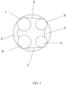
- FIG. 1 is a schematic diagram of a structure of an engine combustion system according to an embodiment of the present application.
- the combustion system includes a combustion chamber 1 and a valve structure.
- the combustion chamber 1 is provided with an air intake side gas extrusion structure 2, an exhaust side gas extrusion structure 3, a front end gas extrusion structure 4 and a rear end gas extrusion structure 5.
- the valve structure includes a first intake valve 6, a second intake valve 7, a first exhaust valve 8 and a second exhaust valve 9; wherein the first intake valve 6 is disposed at one side of the front end of the combustion chamber 1, the second intake valve 7 is disposed at one side of the rear end of the combustion chamber 1 corresponding to the first intake valve 6; the first exhaust valve 8 is disposed at the other side of the front end of the combustion chamber 1, the second exhaust valve 9 is disposed at one side of the rear end of the combustion chamber 1 corresponding to the first exhaust valve 8.
- the air intake side gas extrusion structure 2 is disposed between the first intake valve 6 and the second intake valve 7, the exhaust side gas extrusion structure 3 is disposed between the first exhaust valve 8 and the second exhaust valve 9, and the front end gas extrusion structure 4d is disposed between the first intake valve 6 and the first exhaust valve 8, the rear end gas extrusion structure 5 is disposed between the second intake valve 7 and the second exhaust valve 9.
- the air intake side gas extrusion structure 2, the front end gas extrusion structure 4 and the rear end gas extrusion structure 5 are all provided as flat gas extrusion structures, the gas extrusion structure 3 at exhaust side is an oblique gas extrusion structure.
- the combustion chamber 1 is provided with four gas extrusion structures, and the air intake side gas extrusion structure 2, the front end gas extrusion structure 4 and the rear end gas extrusion structure 5 are all provided as flat gas extrusion structures, and the exhaust side gas extrusion structure 3 is provided as an oblique gas extrusion structure, which can effectively increase a tumble flow ratio and turbulence intensity of mixed gas in the cylinder, increase a gas extrusion gap at the exhaust side, facilitate rapid combustion flame, reduce a risk of knocking, reduce a heat transfer loss in the combustion chamber 1 and improve an efficiency of the combustion system.
- a first flow guide curved surface is arranged between the first intake valve 6 and the first exhaust valve 8, and an intake valve end of the first flow guide curved surface is higher than an exhaust valve end of the first flow guide curved surface.
- a second flow guide curved surface is provided between the second intake valve 7 and the second exhaust valve 9, and an intake valve end of the second flow guide curved surface is higher than an exhaust valve end of the second flow guide curved surface.
- An intake port and an exhaust port in the combustion system are provided as a guide structures, that is, on the flow guide curved surface, the intake valve end is arranged higher than the exhaust valve end.
- the combustion chamber 1 includes a piston, and the top of the piston is convex.
- a large tumble flow ratio can be formed in the cylinder, a larger turbulent intensity, more uniform mixing of fuel and gas, which is beneficial to combustion flame, reduces the risk of preignition and knocking, reduces unburned loss, and at the same time raises a compression ratio to 13, thus improving the thermal efficiency of the engine.
- the combustion system further includes a high-pressure direct injection system 14, wherein the high-pressure direct injection system 14 includes a fuel injector capable of atomizing fuel and injecting it to the combustion chamber 1, then the fuel is rapidly and uniformly mixed with fresh air in the combustion chamber 1, and a turbulent energy center of the mixed gas is at the center of the combustion chamber 1.
- the high-pressure direct injection system 14 includes a fuel injector capable of atomizing fuel and injecting it to the combustion chamber 1, then the fuel is rapidly and uniformly mixed with fresh air in the combustion chamber 1, and a turbulent energy center of the mixed gas is at the center of the combustion chamber 1.
- the high-pressure direct injection system 14 (with a fuel injection pressure > 350bar) can make the fuel atomized more sufficiently, and with an advanced high tumble flow ratio port, the fuel and gas are mixed and burned more sufficiently, and the PN emission in the emission is reduced, which can meet the emission standard without adopting GPF; at the same time, the injection distance of high-pressure direct injection system 14 is shorter, which can reduce the risk of wet wall of fuel in cylinder, avoid preignition of engine and prevent engine from being damaged.
- the combustion system further includes a high-energy ignition system 15, wherein the high-energy ignition system 15 is used for igniting the mixed gas in the combustion chamber 1.
- an air-fuel ratio in the mixed gas in the combustion chamber 1 is equal to 14.7.
- the lean mixed gas is ignited by the high-energy ignition system 15 to improve its combustion stability and ensure that COV (cyclic variation coefficient) ⁇ 3%.
- COV cyclic variation coefficient
- the fuel combustion efficiency is greatly increased, the thermal efficiency of the engine is improved, while emission of CO and THC (total amount of hydrocarbons) is greatly reduced, and emission of NOx is kept at a relatively low level.
- FIG. 2 is a schematic diagram of a structure of a gasoline engine for a hybrid vehicle according to the present application, including a low-pressure EGR system and the engine combustion system described above.
- the low-pressure EGR (exhaust gas recirculation) system is disposed at an exhaust side of the gasoline engine.
- the low-pressure EGR system includes an EGR cooler 18, a three-way catalytic converter structure 17 and a turbocharger compressor 16.
- the three-way catalytic converter structure 17 is connected with an inlet of the EGR cooler 18, and the turbocharger compressor 16 is connected with an outlet of the EGR cooler 18.
- the gasoline engine for hybrid vehicle provided by the embodiment of the present application adopts the combustion system described above in combination with the low-pressure EGR system, and by introducing the three-way catalytic converter 17, a certain amount of exhaust gas can be introduced into the cylinder as demand, reduce a temperature in the cylinder, restrain knocking, advance an ignition angle, and improve effective output work generated by combustion, so as to improve the fuel economy.
- Fresh air is mixed with EGR exhaust gas through an air filter 10, and after being pressurized by the turbocharger compressor 16, it is cooled by the water-air intercooler 11, and then enters the combustion chamber 1 through an intake manifold 13. While in-cylinder fuel injection is carried out by the high-pressure direct injection system 14, and the air-fuel ratio is controlled to be equal to 14.7.
- the high-energy ignition system 15 ignites the homogeneous and lean mixed gas, and exhaust gas after combustion is expelled after being treated by the three-way catalytic converter 17 of post-treatment 21.
- a throttle body 12 is disposed between the water-air intercooler 11 and the intake manifold 13.
- a part of the exhaust gas passing through the three-way catalytic converter 17 returns to the combustion chamber 1 through the EGR system, which can increase the mixing specific heat capacity and total mass in the combustion chamber 1, reduce the combustion temperature, reduce the heat transfer loss, reduce the pumping loss at partial load, and at the same time slow down the combustion velocity, restrain knocking, and ensure that the air-fuel ratio is equal to 14.7.
- the independent water-air intercooler can ensure the temperature of the mixed gas after compression by the turbocharger according to combustion requirements, reduce a pressure drop of the entire intake system.
- the high-pressure direct injection system 14 With the high-pressure direct injection system 14 (with a fuel injection pressure > 350bar), an injection penetration distance and an injection particle size are greatly reduced, a fuel atomization effect is improved, a possibility of wet wall is reduced, and an amount of fuel injection is controlled.
- the lean mixed gas is ignited by the high-energy ignition system 15 to improve its combustion stability (ensuring COV ⁇ 3%). Through the homogeneous lean combustion, the fuel combustion efficiency is greatly increased, the thermal efficiency of the engine is improved, and the emission of CO and the emission of THC are greatly reduced, and the emission of NOx is kept at a relatively low level. Excess CO and THC are converted by the three-way catalytic converter 17 of the post-treatment system, so as to meet emission requirements.
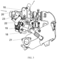
- FIG. 3 is a schematic diagram of a structure of a low-pressure EGR system according to an embodiment of the present application.
- the low-pressure EGR system further includes an EGR valve 19, a hose 22 and a low-pressure intake aluminum pipe 23.
- the EGR valve 19 is connected with an outlet of the EGR cooler 18, the hose 22 is communicated with the EGR valve 19, one end of the low-pressure intake aluminum pipe 23 is communicated with the hose 22, and the other end of the low-pressure intake aluminum pipe 23 is communicated with a turbocharger compressor 16.
- the hose 22 is communicated with the EGR valve 19 to introduce exhaust gas into the low-pressure intake aluminum pipe 23. Fresh air and exhaust gas are mixed in the low-pressure intake aluminum pipe 23 and then entered into the turbocharger compressor 16.
- the turbocharger compressor 16 is fixed directly to a cylinder head of the gasoline engine.
- the EGR valve 19 is used for adjusting opening and controlling a flow rate of the exhaust gas.
- a pressure difference sensor can read the pressure difference before and after the EGR valve 19 and calculate the flow rate of the exhaust gas through the EGR valve 19.
- a filter screen is provided at an inlet of the EGR cooler 18.
- the low-pressure EGR system further includes an EGR pressure regulating valve 20, wherein the EGR pressure regulating valve 20 is communicated with the low-pressure intake aluminum pipe 23. Fresh air enters the low-pressure intake aluminum pipe 23 through the EGR pressure regulating valve 20.
- the EGR pressure regulating valve 20 ensures that the whole engine running region can use EGR by adjusting opening of a valve plate, and there is a certain pressure difference in the EGR passage, so that an EGR rate can be accurately calculated.
- a structure of the three-way catalytic converter 17 includes a three-way catalytic converter 17 and a three-way catalytic converter bracket, and the bracket of the three-way catalytic converter 17 is used for supporting the three-way catalytic converter 17.
- the three-way catalytic converter 17 is fixed to the cylinder head and the cylinder block by an upper support point of the three-way catalytic converter bracket, and a lower support point of the three-way catalytic converter bracket is fixed to the cylinder block of the gasoline engine.
- a third aspect of the embodiment of the present application discloses a vehicle including the engine combustion system or the gasoline engine for hybrid vehicle described above.
Landscapes
- Engineering & Computer Science (AREA)
- Chemical & Material Sciences (AREA)
- Combustion & Propulsion (AREA)
- Mechanical Engineering (AREA)
- General Engineering & Computer Science (AREA)
- Output Control And Ontrol Of Special Type Engine (AREA)
- Hybrid Electric Vehicles (AREA)
- Exhaust-Gas Circulating Devices (AREA)
Abstract
Description
- The present application relates to the technical field of engines, in particular to an engine combustion system, a gasoline engine for hybrid vehicle and a vehicle.
- Developing new energy vehicles has become one of the key development strategies in China. Hybrid vehicles and electric vehicles have better fuel economy and emission performance than traditional vehicles, and engines are of great significance for hybrid vehicles.
- At present, turbocharged direct injection engines used in hybrid vehicles available in market has high power increase and strengthening degree, high combustion temperature in cylinders, easy occurrence of knocking of the engine, and high fuel consumption caused by delayed ignition angle, in addition, the turbocharged direct injection engine controls and adjusts air intake of engine through a throttle valve, which leads to high pumping loss, reduced effective output work of the engine and poor fuel economy. Besides, PN (Particle Number) emission of the turbocharged direct injection engine is poor, so a GPF (Gasoline Particulate Filter) is required to be added in post-treatment system. The GPF has high cost, and active regeneration of the GPF requires using post fuel injection to burn the carbon particles in GPF at the high temperature, which leads to poor fuel economy.
- An aim of the present application is to solve the technical problem of poor fuel economy of engines in the prior art.
- In order to solve the above technical problem, a first aspect of the present application discloses an engine combustion system including a combustion chamber and a valve structure;
- the combustion chamber is provided with an air intake side gas extrusion structure, an exhaust side gas extrusion structure, a front end gas extrusion structure and a rear end gas extrusion structure;
- the valve structure includes a first intake valve, a second intake valve, a first exhaust valve and a second exhaust valve; wherein the first intake valve is disposed at one side of a front end of the combustion chamber, and the second intake valve is disposed at one side of a rear end of the combustion chamber corresponding to the first intake valve; the first exhaust valve is disposed at the other side of the front end of the combustion chamber, and the second exhaust valve is disposed at one side of the rear end of the combustion chamber corresponding to the first exhaust valve;
- the air intake side gas extrusion structure is disposed between the first intake valve and the second intake valve, the exhaust side gas extrusion structure is disposed between the first exhaust valve and the second exhaust valve, the front end gas extrusion structure is disposed between the first intake valve and the first exhaust valve, and the rear end gas extrusion structure is disposed between the second intake valve and the second exhaust valve; and
- the air intake side gas extrusion structure, the front end gas extrusion structure and the rear end gas extrusion structure are all flat gas extrusion structures, and the exhaust side gas extrusion structure is an oblique gas extrusion structure.
- Further, a first flow guide curved surface is disposed between the first intake valve and the first exhaust valve, and an intake valve end of the first flow guide curved surface is higher than an exhaust valve end of the first flow guide curved surface.
- Further, a second flow guide curved surface is disposed between the first intake valve and the first exhaust valve, and an intake valve end of the second flow guide curved surface is higher than an exhaust valve end of the first second curved surface.
- Further, the combustion chamber includes a piston, and the piston is convex at its top.
- Further, the combustion system further includes a high-pressure direct injection system including a fuel injector capable of atomizing fuel and injecting it into the combustion chamber.
- Further, the combustion system further includes a high-energy ignition system for igniting mixed gas in the combustion chamber.
- A second aspect of the present application discloses a gasoline engine for hybrid vehicle, including a low-pressure EGR (Exhaust Gas Recirculation) system and the engine combustion system; the low-pressure EGR system is disposed at an exhaust side of the gasoline engine; the low-pressure EGR system includes an EGR cooler, a three-way catalytic converter structure and a turbocharger compressor; the three-way catalytic converter structure is connected with an inlet of the EGR cooler, and the turbocharger compressor is connected with an outlet of the EGR cooler.
- Further, the low-pressure EGR system further includes an EGR valve, a hose and a low-pressure intake aluminum pipe; the EGR valve is connected with the outlet of the EGR cooler, the hose is communicated with the EGR valve, one end of the low-pressure intake aluminum pipe is communicated with the hose, and the other end of the low-pressure air intake aluminum pipe is communicated with the turbocharger compressor.
- Further, the low-pressure EGR system further includes an EGR pressure regulating valve, and the EGR pressure regulating valve is communicated with the low-pressure intake aluminum pipe.
- Further, the low-pressure EGR system further includes a three-way catalytic converter bracket for supporting the three-way catalytic converter.
- A third aspect of the present application discloses a vehicle, including the gasoline engine for hybrid vehicle described above.
- By adopting the technical solution described above, the present application has the following beneficial effects:
in the combustion system of the engine provided by the present application, the combustion chamber is provided with an air intake side gas extrusion structure, an air-exhaust side gas extrusion structure, a front end gas extrusion structure and a rear end gas extrusion structure; also, the air intake side gas extrusion structure , the front end gas extrusion structure and the rear end gas extrusion structure are all provided as flat gas extrusion structures, and the exhaust side gas extrusion structure is provided as an oblique gas extrusion structure, which is beneficial to improvement of tumble flow ratio and turbulence intensity in the cylinder, and makes the structure of the combustion chamber more compact, reduces a heat transfer loss in the combustion chamber and improves a combustion efficiency. - The gasoline engine for hybrid vehicle provided by the present application adopts the combustion system described above in combination with the low-pressure EGR system, and by introducing a three-way catalytic converter, a certain amount of exhaust gas can be introduced into the cylinder as demand, reduce the temperature in the cylinder, restrain knocking, advance the ignition angle, and improve the effective output work generated by combustion, so as to improve the fuel economy.
- In order to more clearly explain technical solutions in the embodiments of the present application, the drawings required to be used in the description of embodiments will be briefly described below, and it will be apparent that the accompanying drawings described below are only some embodiments of the present application, and for those skilled in the art, other drawings may be obtained according to these accompanying drawings without inventive effort.
-
FIG. 1 is a schematic diagram of a structure of an engine combustion system according to an embodiment of the present application. -
FIG. 2 is a schematic diagram of a structure of a gasoline engine for hybrid vehicle according to an embodiment of the present application. -
FIG. 3 a schematic diagram of a structure of a low-pressure EGR system of a gasoline engine for hybrid vehicle according to an embodiment of the present application. - The followings are used for supplementary explanations of the accompanying drawings:
- 1-combustion chamber; 2-air intake side gas extrusion structure; 3-exhaust side gas extrusion structure; 4-front end gas extrusion structure;
- 5-rear end gas extrusion structure; 6-first intake valve; 7-second intake valve; 8-first exhaust valve; 9-second exhaust valve;
- 10-air filter; 11-water-air intercooler; 12-throttle body; 13-intake manifold; 14-high-pressure direct injection system; 15-high-energy ignition system; 16- turbocharger compressor; 17-three-way catalytic converter; 18-EGR cooler; 19-EGR valve; 20-EGR pressure regulating valve; 21-post-treatment; 22-hose; 23-low-pressure intake aluminum pipe.
- The technical solution in the embodiments of the present application will be clearly and completely described in the following with reference to the accompanying drawings in the embodiments of the present application. It will be apparent that the described embodiments are only part of but not all of the embodiments of the present application. Based on the embodiments in the present application, all other embodiments obtained by those skilled in the art without making creative efforts fall within the scope of protection of the present application.
- "One embodiment" or "embodiments" herein refers to a particular feature, structure, or characteristic that may be included in at least one implementation of the present application. In the description of embodiments of the present application, it should be understood that the orientation or position relationships indicated by the terms "upper", "lower", "top", "bottom" are based on the orientation or position relationships shown in the drawings, which is only for convenience of describing the embodiments of the present application and simplifying the description, rather than indicating or implying that the devices or elements referred to must have the specific orientation, be constructed and operated in the specific orientation, and thus cannot be interpreted as a limitation on the present application. Furthermore, the terms "first" and "second" are used for descriptive purposes only and cannot be understood as indicating or implying relative importance or implying the amount of technical features indicated. Thus, features defined with "first" and "second" may explicitly or implicitly include one or more of such features. Moreover, the terms "first", "second", etc. are used to distinguish similar objects and not necessary to be used for describing a particular order or sequence. It should be understood that the data used in such way can be interchanged where appropriate, so that the embodiments of the present application described herein can be implemented in an order other than those illustrated or described herein.
- Referring to
FIG. 1, FIG. 1 is a schematic diagram of a structure of an engine combustion system according to an embodiment of the present application. The combustion system includes acombustion chamber 1 and a valve structure. - The
combustion chamber 1 is provided with an air intake sidegas extrusion structure 2, an exhaust sidegas extrusion structure 3, a front endgas extrusion structure 4 and a rear endgas extrusion structure 5. - The valve structure includes a
first intake valve 6, asecond intake valve 7, afirst exhaust valve 8 and asecond exhaust valve 9; wherein thefirst intake valve 6 is disposed at one side of the front end of thecombustion chamber 1, thesecond intake valve 7 is disposed at one side of the rear end of thecombustion chamber 1 corresponding to thefirst intake valve 6; thefirst exhaust valve 8 is disposed at the other side of the front end of thecombustion chamber 1, thesecond exhaust valve 9 is disposed at one side of the rear end of thecombustion chamber 1 corresponding to thefirst exhaust valve 8. - The air intake side
gas extrusion structure 2 is disposed between thefirst intake valve 6 and thesecond intake valve 7, the exhaust sidegas extrusion structure 3 is disposed between thefirst exhaust valve 8 and thesecond exhaust valve 9, and the front end gas extrusion structure 4d is disposed between thefirst intake valve 6 and thefirst exhaust valve 8, the rear endgas extrusion structure 5 is disposed between thesecond intake valve 7 and thesecond exhaust valve 9. - The air intake side
gas extrusion structure 2, the front endgas extrusion structure 4 and the rear endgas extrusion structure 5 are all provided as flat gas extrusion structures, thegas extrusion structure 3 at exhaust side is an oblique gas extrusion structure. - In the engine combustion system provided by the present application, the
combustion chamber 1 is provided with four gas extrusion structures, and the air intake sidegas extrusion structure 2, the front endgas extrusion structure 4 and the rear endgas extrusion structure 5 are all provided as flat gas extrusion structures, and the exhaust sidegas extrusion structure 3 is provided as an oblique gas extrusion structure, which can effectively increase a tumble flow ratio and turbulence intensity of mixed gas in the cylinder, increase a gas extrusion gap at the exhaust side, facilitate rapid combustion flame, reduce a risk of knocking, reduce a heat transfer loss in thecombustion chamber 1 and improve an efficiency of the combustion system. - In the embodiment of the present application, a first flow guide curved surface is arranged between the
first intake valve 6 and thefirst exhaust valve 8, and an intake valve end of the first flow guide curved surface is higher than an exhaust valve end of the first flow guide curved surface. - A second flow guide curved surface is provided between the
second intake valve 7 and thesecond exhaust valve 9, and an intake valve end of the second flow guide curved surface is higher than an exhaust valve end of the second flow guide curved surface. An intake port and an exhaust port in the combustion system are provided as a guide structures, that is, on the flow guide curved surface, the intake valve end is arranged higher than the exhaust valve end. During an intake process, a high-speed airflow generated by the intake port flows from the intake side to the exhaust side, thus forming a large tumble flow in the engine cylinder, thereby reducing occurrence of a dead zone of flow rate at the exhaust side and cooling the temperature at the exhaust side. - In the embodiment of the present application, the
combustion chamber 1 includes a piston, and the top of the piston is convex. - In the embodiment of the present application, through the design of the above-mentioned flow guide curved surface, combined with the design of the gas extrusion structure of the
combustion chamber 1, and combined with the optimization of the convex piston top, a large tumble flow ratio can be formed in the cylinder, a larger turbulent intensity, more uniform mixing of fuel and gas, which is beneficial to combustion flame, reduces the risk of preignition and knocking, reduces unburned loss, and at the same time raises a compression ratio to 13, thus improving the thermal efficiency of the engine. - In embodiment of the present application, the combustion system further includes a high-pressure direct injection system 14, wherein the high-pressure direct injection system 14 includes a fuel injector capable of atomizing fuel and injecting it to the
combustion chamber 1, then the fuel is rapidly and uniformly mixed with fresh air in thecombustion chamber 1, and a turbulent energy center of the mixed gas is at the center of thecombustion chamber 1. In the embodiment of the present application, the high-pressure direct injection system 14 (with a fuel injection pressure > 350bar) can make the fuel atomized more sufficiently, and with an advanced high tumble flow ratio port, the fuel and gas are mixed and burned more sufficiently, and the PN emission in the emission is reduced, which can meet the emission standard without adopting GPF; at the same time, the injection distance of high-pressure direct injection system 14 is shorter, which can reduce the risk of wet wall of fuel in cylinder, avoid preignition of engine and prevent engine from being damaged. - In the embodiment of the present application, the combustion system further includes a high-
energy ignition system 15, wherein the high-energy ignition system 15 is used for igniting the mixed gas in thecombustion chamber 1. In the embodiment of the present application, an air-fuel ratio in the mixed gas in thecombustion chamber 1 is equal to 14.7. The lean mixed gas is ignited by the high-energy ignition system 15 to improve its combustion stability and ensure that COV (cyclic variation coefficient) < 3%. By homogeneous lean combustion, the fuel combustion efficiency is greatly increased, the thermal efficiency of the engine is improved, while emission of CO and THC (total amount of hydrocarbons) is greatly reduced, and emission of NOx is kept at a relatively low level. - A second aspect of the present application discloses a gasoline engine for a hybrid vehicle,
FIG. 2 is a schematic diagram of a structure of a gasoline engine for a hybrid vehicle according to the present application, including a low-pressure EGR system and the engine combustion system described above. - The low-pressure EGR (exhaust gas recirculation) system is disposed at an exhaust side of the gasoline engine. The low-pressure EGR system includes an
EGR cooler 18, a three-waycatalytic converter structure 17 and aturbocharger compressor 16. The three-waycatalytic converter structure 17 is connected with an inlet of theEGR cooler 18, and theturbocharger compressor 16 is connected with an outlet of theEGR cooler 18. - The gasoline engine for hybrid vehicle provided by the embodiment of the present application adopts the combustion system described above in combination with the low-pressure EGR system, and by introducing the three-way
catalytic converter 17, a certain amount of exhaust gas can be introduced into the cylinder as demand, reduce a temperature in the cylinder, restrain knocking, advance an ignition angle, and improve effective output work generated by combustion, so as to improve the fuel economy. - In the embodiment of that present application, a working flow of the gasoline engine is described as follows in combination with
FIG. 2 . Fresh air is mixed with EGR exhaust gas through anair filter 10, and after being pressurized by theturbocharger compressor 16, it is cooled by the water-air intercooler 11, and then enters thecombustion chamber 1 through anintake manifold 13. While in-cylinder fuel injection is carried out by the high-pressure direct injection system 14, and the air-fuel ratio is controlled to be equal to 14.7. The high-energy ignition system 15 ignites the homogeneous and lean mixed gas, and exhaust gas after combustion is expelled after being treated by the three-waycatalytic converter 17 ofpost-treatment 21. - A
throttle body 12 is disposed between the water-air intercooler 11 and theintake manifold 13. A part of the exhaust gas passing through the three-waycatalytic converter 17 returns to thecombustion chamber 1 through the EGR system, which can increase the mixing specific heat capacity and total mass in thecombustion chamber 1, reduce the combustion temperature, reduce the heat transfer loss, reduce the pumping loss at partial load, and at the same time slow down the combustion velocity, restrain knocking, and ensure that the air-fuel ratio is equal to 14.7. The independent water-air intercooler can ensure the temperature of the mixed gas after compression by the turbocharger according to combustion requirements, reduce a pressure drop of the entire intake system. With the high-pressure direct injection system 14 (with a fuel injection pressure > 350bar), an injection penetration distance and an injection particle size are greatly reduced, a fuel atomization effect is improved, a possibility of wet wall is reduced, and an amount of fuel injection is controlled. The lean mixed gas is ignited by the high-energy ignition system 15 to improve its combustion stability (ensuring COV<3%). Through the homogeneous lean combustion, the fuel combustion efficiency is greatly increased, the thermal efficiency of the engine is improved, and the emission of CO and the emission of THC are greatly reduced, and the emission of NOx is kept at a relatively low level. Excess CO and THC are converted by the three-waycatalytic converter 17 of the post-treatment system, so as to meet emission requirements. -
FIG. 3 is a schematic diagram of a structure of a low-pressure EGR system according to an embodiment of the present application. The low-pressure EGR system further includes anEGR valve 19, ahose 22 and a low-pressureintake aluminum pipe 23. - The
EGR valve 19 is connected with an outlet of theEGR cooler 18, thehose 22 is communicated with theEGR valve 19, one end of the low-pressureintake aluminum pipe 23 is communicated with thehose 22, and the other end of the low-pressureintake aluminum pipe 23 is communicated with aturbocharger compressor 16. Thehose 22 is communicated with theEGR valve 19 to introduce exhaust gas into the low-pressureintake aluminum pipe 23. Fresh air and exhaust gas are mixed in the low-pressureintake aluminum pipe 23 and then entered into theturbocharger compressor 16. Theturbocharger compressor 16 is fixed directly to a cylinder head of the gasoline engine. In the embodiment of the present application, theEGR valve 19 is used for adjusting opening and controlling a flow rate of the exhaust gas. A pressure difference sensor can read the pressure difference before and after theEGR valve 19 and calculate the flow rate of the exhaust gas through theEGR valve 19. In the embodiment of the present application, a filter screen is provided at an inlet of theEGR cooler 18. - In the embodiment of the present application, the low-pressure EGR system further includes an EGR
pressure regulating valve 20, wherein the EGRpressure regulating valve 20 is communicated with the low-pressureintake aluminum pipe 23. Fresh air enters the low-pressureintake aluminum pipe 23 through the EGRpressure regulating valve 20. The EGRpressure regulating valve 20 ensures that the whole engine running region can use EGR by adjusting opening of a valve plate, and there is a certain pressure difference in the EGR passage, so that an EGR rate can be accurately calculated. - In the embodiment of the present application, a structure of the three-way
catalytic converter 17 includes a three-waycatalytic converter 17 and a three-way catalytic converter bracket, and the bracket of the three-waycatalytic converter 17 is used for supporting the three-waycatalytic converter 17. The three-waycatalytic converter 17 is fixed to the cylinder head and the cylinder block by an upper support point of the three-way catalytic converter bracket, and a lower support point of the three-way catalytic converter bracket is fixed to the cylinder block of the gasoline engine. - A third aspect of the embodiment of the present application discloses a vehicle including the engine combustion system or the gasoline engine for hybrid vehicle described above.
- The above are only preferred embodiments of the present application and are not intended to limit the present application. Any modification, equivalent replacement, improvement, etc. made within the spirit and principles of the present application shall be included in the scope of protection of the present application.
Claims (10)
- An engine combustion system, comprising a combustion chamber (1) and a valve structure; whereinthe combustion chamber (1) is provided with an air intake side gas extrusion structure (2), an exhaust side gas extrusion structure (3), a front end gas extrusion structure (4) and a rear end gas extrusion structure (5);the valve structure comprises a first intake valve (6), a second intake valve (7), a first exhaust valve (8) and a second exhaust valve (9); wherein the first intake valve (6) is disposed at one side of a front end of the combustion chamber (1), and the second intake valve (7) is disposed at one side of a rear end of the combustion chamber (1) corresponding to the first intake valve (6); the first exhaust valve (8) is disposed at the other side of the front end of the combustion chamber (1), and the second exhaust valve (9) is disposed at one side of the rear end of the combustion chamber (1) corresponding to the first exhaust valve (8);the air intake side gas extrusion structure (2) is disposed between the first intake valve (6) and the second intake valve (7), the exhaust side gas extrusion structure (3) is disposed between the first exhaust valve (8) and the second exhaust valve (9), the front end gas extrusion structure (4) is disposed between the first intake valve (6) and the first exhaust valve (8), and the rear end gas extrusion structure (5) is disposed between the second intake valve (7) and the second exhaust valve (9); andthe air intake side gas extrusion structure (2), the front end gas extrusion structure (4) and the rear end gas extrusion structure (5) are all flat gas extrusion structures, and the exhaust side gas extrusion structure (3) is an oblique gas extrusion structure.
- The engine combustion system according to claim 1, wherein a first flow guide curved surface is disposed between the first intake valve (6) and the first exhaust valve (8), an intake valve end of the first flow guide curved surface is higher than an exhaust valve end of the first flow guide curved surface; and
a second flow guide curved surface is disposed between the first intake valve (6) and the first exhaust valve (8), and an intake valve end of the second flow guide curved surface is higher than an exhaust valve end of the second flow guide curved surface. - The engine combustion system according to claim 1, wherein the combustion chamber (1) comprises a piston, and the piston is convex at its top.
- The engine combustion system according to claim 1, further comprising a high-pressure direct injection system (14), and the high-pressure direct injection system (14) comprises a fuel injector capable of atomizing fuel and injecting the fuel into the combustion chamber (1).
- The engine combustion system according to claim 1, further comprising a high-energy ignition system (15) for igniting a mixed gas in the combustion chamber (1).
- A gasoline engine for hybrid vehicle, comprising a low-pressure exhaust gas recirculation (EGR) system and the engine combustion system according to any one of claims 1 to 5;wherein the low-pressure EGR system is disposed at an exhaust side of the gasoline engine; the low-pressure EGR system comprises an EGR cooler (18), a three-way catalytic converter (17) and a turbocharger compressor (16); andthe three-way catalytic converter (17) is connected with an inlet of the EGR cooler (18), and the turbocharger compressor (16) is connected with an outlet of the EGR cooler (18).
- The gasoline engine for hybrid vehicle according to claim 6, wherein the low-pressure EGR system further comprises an EGR valve (19), a hose (22) and a low-pressure intake aluminum pipe (23);
the EGR valve (19) is connected with the outlet of the EGR cooler (18), and the hose (22) is communicated with the EGR valve (19), one end of the low-pressure intake aluminum pipe (23) is communicated with the hose (22), and the other end of the low-pressure intake aluminum pipe (23) is communicated with the turbocharger compressor (16). - The gasoline engine for hybrid vehicle according to claim 7, wherein the low-pressure EGR system further comprises an EGR pressure regulating valve (20);
the EGR pressure regulating valve (20) is communicated with the low-pressure intake aluminum pipe (23). - The gasoline engine for hybrid vehicle according to claim 6, wherein the low-pressure EGR system further comprises a three-way catalytic converter bracket for supporting the three-way catalytic converter (17).
- A vehicle, comprising the engine combustion system according to any one of claims 1 to 5 or the gasoline engine for hybrid vehicle according to any one of claims 6 to 9.
Applications Claiming Priority (1)
| Application Number | Priority Date | Filing Date | Title |
|---|---|---|---|
| PCT/CN2020/103396 WO2022016403A1 (en) | 2020-07-22 | 2020-07-22 | Engine combustion system, gasoline engine for hybrid vehicle, and vehicle |
Publications (3)
| Publication Number | Publication Date |
|---|---|
| EP4151849A1 true EP4151849A1 (en) | 2023-03-22 |
| EP4151849A4 EP4151849A4 (en) | 2023-07-19 |
| EP4151849B1 EP4151849B1 (en) | 2026-04-15 |
Family
ID=79728436
Family Applications (1)
| Application Number | Title | Priority Date | Filing Date |
|---|---|---|---|
| EP20945756.3A Active EP4151849B1 (en) | 2020-07-22 | 2020-07-22 | Engine combustion system, gasoline engine for hybrid vehicle, and vehicle |
Country Status (3)
| Country | Link |
|---|---|
| EP (1) | EP4151849B1 (en) |
| CN (1) | CN115943254A (en) |
| WO (1) | WO2022016403A1 (en) |
Family Cites Families (10)
| Publication number | Priority date | Publication date | Assignee | Title |
|---|---|---|---|---|
| JPH10325325A (en) * | 1997-05-27 | 1998-12-08 | Kubota Corp | Combustion chamber of spark ignition engine |
| JP2006152825A (en) * | 2004-11-25 | 2006-06-15 | Toyota Motor Corp | Combustion chamber of internal combustion engine |
| JP6115197B2 (en) * | 2013-03-08 | 2017-04-19 | スズキ株式会社 | Combustion chamber structure of internal combustion engine |
| CN204851420U (en) * | 2015-06-15 | 2015-12-09 | 华晨汽车集团控股有限公司 | Supercharged engine cylinder cap combustion chamber structure |
| JP6627844B2 (en) * | 2017-10-24 | 2020-01-08 | マツダ株式会社 | engine |
| CN208236522U (en) * | 2018-01-02 | 2018-12-14 | 宁波吉利罗佑发动机零部件有限公司 | Engine aspirating system and automobile |
| CN108869006A (en) * | 2018-06-20 | 2018-11-23 | 奇瑞汽车股份有限公司 | Small-displacement gasoline engine combustion system |
| CN208831093U (en) * | 2018-08-07 | 2019-05-07 | 奇瑞汽车股份有限公司 | Combustion system of direct injection supercharged gasoline engine |
| CN109281750B (en) * | 2018-09-25 | 2020-08-18 | 宁波吉利罗佑发动机零部件有限公司 | A high compression ratio engine combustion chamber |
| CN210264972U (en) * | 2019-07-12 | 2020-04-07 | 奇瑞汽车股份有限公司 | Combustion system of direct-injection supercharged gasoline engine in middle-placed cylinder |
-
2020
- 2020-07-22 CN CN202080100480.2A patent/CN115943254A/en active Pending
- 2020-07-22 EP EP20945756.3A patent/EP4151849B1/en active Active
- 2020-07-22 WO PCT/CN2020/103396 patent/WO2022016403A1/en not_active Ceased
Also Published As
| Publication number | Publication date |
|---|---|
| EP4151849A4 (en) | 2023-07-19 |
| WO2022016403A1 (en) | 2022-01-27 |
| CN115943254A (en) | 2023-04-07 |
| EP4151849B1 (en) | 2026-04-15 |
Similar Documents
| Publication | Publication Date | Title |
|---|---|---|
| CN104937253B (en) | Internally cooled exhaust gas recirculation system for an internal combustion engine and method thereof | |
| CN102052205B (en) | Hybrid hydrogen and oxygen compression ignition-type diesel oil internal combustion engine and control method thereof | |
| CN103573480B (en) | A kind of pure oxygen electromotor and method for controlling combustion thereof | |
| CN105422327B (en) | The variable EGR gas handling systems of composite injection bi-fuel internal combustion engine and method | |
| CN111472891A (en) | Combustion system and control method of diesel-piloted natural gas engine | |
| CN111042955B (en) | Engine system and combustion method | |
| CN103291472A (en) | Compression ignition engine homogeneous combustion control method with temperature in cylinder controlled quantitatively | |
| CN104989539A (en) | Internal combustion engine for direct injection of double-gas fuel in cylinder under EGR condition and control method | |
| CN110848035A (en) | Combustion control method and control system of natural gas engine | |
| CN108843446B (en) | Gasoline engine combustion control method suitable for medium and heavy duty vehicle and gasoline engine | |
| CN102444507B (en) | Gas inlet and outlet system for homogeneous charge compression ignition (HCCI) engine, gas inlet control method and engine | |
| CN107939517B (en) | Jet ignition-based engine ultrahigh compression ratio combustion control device and method | |
| CN106762294A (en) | A kind of method of flexible control engine combustion mode | |
| CN108180071A (en) | A kind of gas handling system suitable for Incylinder direct injection hydrogen internal combustion engine | |
| CN110529321A (en) | A kind of in-cylinder hydrogen injection rotor electromechanical ignition control method | |
| CN209398491U (en) | A control system that can effectively expand the efficient and clean operation range of gasoline compression ignition | |
| CN204961094U (en) | Two gaseous fuel's of direct injection internal -combustion engine under EGR condition | |
| CN102996223A (en) | Diesel Engine Premix Combustion System | |
| EP4151849B1 (en) | Engine combustion system, gasoline engine for hybrid vehicle, and vehicle | |
| CN107905880B (en) | An engine with a water injection system | |
| Luo et al. | Controlling strategy for the performance and NOx emissions of the hydrogen internal combustion engines with a turbocharger | |
| CN115962052B (en) | Ammonia diesel dual-fuel engine adopting double-loop linkage supercharging EGR and combustion method thereof | |
| CN214997915U (en) | Hydrogen ethanol engine for range extender | |
| CN203532106U (en) | Pure oxygen engine | |
| CN116378816A (en) | An opposed-piston two-stroke engine |
Legal Events
| Date | Code | Title | Description |
|---|---|---|---|
| STAA | Information on the status of an ep patent application or granted ep patent |
Free format text: STATUS: THE INTERNATIONAL PUBLICATION HAS BEEN MADE |
|
| PUAI | Public reference made under article 153(3) epc to a published international application that has entered the european phase |
Free format text: ORIGINAL CODE: 0009012 |
|
| STAA | Information on the status of an ep patent application or granted ep patent |
Free format text: STATUS: REQUEST FOR EXAMINATION WAS MADE |
|
| 17P | Request for examination filed |
Effective date: 20221214 |
|
| AK | Designated contracting states |
Kind code of ref document: A1 Designated state(s): AL AT BE BG CH CY CZ DE DK EE ES FI FR GB GR HR HU IE IS IT LI LT LU LV MC MK MT NL NO PL PT RO RS SE SI SK SM TR |
|
| A4 | Supplementary search report drawn up and despatched |
Effective date: 20230616 |
|
| RIC1 | Information provided on ipc code assigned before grant |
Ipc: F02B 23/08 20060101ALI20230612BHEP Ipc: F02F 1/24 20060101AFI20230612BHEP |
|
| DAV | Request for validation of the european patent (deleted) | ||
| DAX | Request for extension of the european patent (deleted) | ||
| GRAP | Despatch of communication of intention to grant a patent |
Free format text: ORIGINAL CODE: EPIDOSNIGR1 |
|
| STAA | Information on the status of an ep patent application or granted ep patent |
Free format text: STATUS: GRANT OF PATENT IS INTENDED |
|
| INTG | Intention to grant announced |
Effective date: 20251114 |
|
| GRAS | Grant fee paid |
Free format text: ORIGINAL CODE: EPIDOSNIGR3 |
|
| GRAA | (expected) grant |
Free format text: ORIGINAL CODE: 0009210 |
|
| STAA | Information on the status of an ep patent application or granted ep patent |
Free format text: STATUS: THE PATENT HAS BEEN GRANTED |
|
| GRAT | Correction requested after decision to grant or after decision to maintain patent in amended form |
Free format text: ORIGINAL CODE: EPIDOSNCDEC |
|
| AK | Designated contracting states |
Kind code of ref document: B1 Designated state(s): AL AT BE BG CH CY CZ DE DK EE ES FI FR GB GR HR HU IE IS IT LI LT LU LV MC MK MT NL NO PL PT RO RS SE SI SK SM TR |
|
| RAP3 | Party data changed (applicant data changed or rights of an application transferred) |
Owner name: AUROBAY (NINGBO) INTELLIGENT TECHNOLOGY CO., LTD. Owner name: AUROBAY TECHNOLOGY CO., LTD. Owner name: ZHEJIANG GEELY HOLDING GROUP CO., LTD. |
|
| REG | Reference to a national code |
Ref country code: CH Ref legal event code: F10 Free format text: ST27 STATUS EVENT CODE: U-0-0-F10-F00 (AS PROVIDED BY THE NATIONAL OFFICE) Effective date: 20260415 |
|
| REG | Reference to a national code |
Ref country code: DE Ref legal event code: R081 Ref document number: 602020070598 Country of ref document: DE Owner name: AUROBAY (NINGBO) INTELLIGENT TECHNOLOGY CO., L, CN Free format text: FORMER OWNERS: AUROBAY (NINGBO) INTELLIGENT TECHNOLOGY CO., LTD., NINGBO, ZHEJIANG, CN; AUROBAY TECHNOLOGY CO., LTD., NINGBO, ZHEJIANG, CN; ZHEJIANG GEELY HOLDING GROUP CO., LTD., HANGZHOU, ZHEJIANG, CN Ref country code: DE Ref legal event code: R081 Ref document number: 602020070598 Country of ref document: DE Owner name: AUROBAY TECHNOLOGY CO., LTD., NINGBO, CN Free format text: FORMER OWNERS: AUROBAY (NINGBO) INTELLIGENT TECHNOLOGY CO., LTD., NINGBO, ZHEJIANG, CN; AUROBAY TECHNOLOGY CO., LTD., NINGBO, ZHEJIANG, CN; ZHEJIANG GEELY HOLDING GROUP CO., LTD., HANGZHOU, ZHEJIANG, CN |
|
| REG | Reference to a national code |
Ref country code: CH Ref legal event code: Q17 Free format text: ST27 STATUS EVENT CODE: U-0-0-Q10-Q17 (AS PROVIDED BY THE NATIONAL OFFICE) Effective date: 20260423 |