EP4151456A1 - Power system apparatus - Google Patents
Power system apparatus Download PDFInfo
- Publication number
- EP4151456A1 EP4151456A1 EP22194910.0A EP22194910A EP4151456A1 EP 4151456 A1 EP4151456 A1 EP 4151456A1 EP 22194910 A EP22194910 A EP 22194910A EP 4151456 A1 EP4151456 A1 EP 4151456A1
- Authority
- EP
- European Patent Office
- Prior art keywords
- charge
- power supply
- rank
- discharge
- demand
- Prior art date
- Legal status (The legal status is an assumption and is not a legal conclusion. Google has not performed a legal analysis and makes no representation as to the accuracy of the status listed.)
- Pending
Links
Images


Classifications
-
- B—PERFORMING OPERATIONS; TRANSPORTING
- B60—VEHICLES IN GENERAL
- B60L—PROPULSION OF ELECTRICALLY-PROPELLED VEHICLES; SUPPLYING ELECTRIC POWER FOR AUXILIARY EQUIPMENT OF ELECTRICALLY-PROPELLED VEHICLES; ELECTRODYNAMIC BRAKE SYSTEMS FOR VEHICLES IN GENERAL; MAGNETIC SUSPENSION OR LEVITATION FOR VEHICLES; MONITORING OPERATING VARIABLES OF ELECTRICALLY-PROPELLED VEHICLES; ELECTRIC SAFETY DEVICES FOR ELECTRICALLY-PROPELLED VEHICLES
- B60L55/00—Arrangements for supplying energy stored within a vehicle to a power network, i.e. vehicle-to-grid [V2G] arrangements
-
- B—PERFORMING OPERATIONS; TRANSPORTING
- B60—VEHICLES IN GENERAL
- B60L—PROPULSION OF ELECTRICALLY-PROPELLED VEHICLES; SUPPLYING ELECTRIC POWER FOR AUXILIARY EQUIPMENT OF ELECTRICALLY-PROPELLED VEHICLES; ELECTRODYNAMIC BRAKE SYSTEMS FOR VEHICLES IN GENERAL; MAGNETIC SUSPENSION OR LEVITATION FOR VEHICLES; MONITORING OPERATING VARIABLES OF ELECTRICALLY-PROPELLED VEHICLES; ELECTRIC SAFETY DEVICES FOR ELECTRICALLY-PROPELLED VEHICLES
- B60L53/00—Methods of charging batteries, specially adapted for electric vehicles; Charging stations or on-board charging equipment therefor; Exchange of energy storage elements in electric vehicles
- B60L53/60—Monitoring or controlling charging stations
- B60L53/67—Controlling two or more charging stations
-
- B—PERFORMING OPERATIONS; TRANSPORTING
- B60—VEHICLES IN GENERAL
- B60L—PROPULSION OF ELECTRICALLY-PROPELLED VEHICLES; SUPPLYING ELECTRIC POWER FOR AUXILIARY EQUIPMENT OF ELECTRICALLY-PROPELLED VEHICLES; ELECTRODYNAMIC BRAKE SYSTEMS FOR VEHICLES IN GENERAL; MAGNETIC SUSPENSION OR LEVITATION FOR VEHICLES; MONITORING OPERATING VARIABLES OF ELECTRICALLY-PROPELLED VEHICLES; ELECTRIC SAFETY DEVICES FOR ELECTRICALLY-PROPELLED VEHICLES
- B60L50/00—Electric propulsion with power supplied within the vehicle
- B60L50/50—Electric propulsion with power supplied within the vehicle using propulsion power supplied by batteries or fuel cells
- B60L50/60—Electric propulsion with power supplied within the vehicle using propulsion power supplied by batteries or fuel cells using power supplied by batteries
-
- B—PERFORMING OPERATIONS; TRANSPORTING
- B60—VEHICLES IN GENERAL
- B60L—PROPULSION OF ELECTRICALLY-PROPELLED VEHICLES; SUPPLYING ELECTRIC POWER FOR AUXILIARY EQUIPMENT OF ELECTRICALLY-PROPELLED VEHICLES; ELECTRODYNAMIC BRAKE SYSTEMS FOR VEHICLES IN GENERAL; MAGNETIC SUSPENSION OR LEVITATION FOR VEHICLES; MONITORING OPERATING VARIABLES OF ELECTRICALLY-PROPELLED VEHICLES; ELECTRIC SAFETY DEVICES FOR ELECTRICALLY-PROPELLED VEHICLES
- B60L53/00—Methods of charging batteries, specially adapted for electric vehicles; Charging stations or on-board charging equipment therefor; Exchange of energy storage elements in electric vehicles
- B60L53/30—Constructional details of charging stations
- B60L53/305—Communication interfaces
-
- B—PERFORMING OPERATIONS; TRANSPORTING
- B60—VEHICLES IN GENERAL
- B60L—PROPULSION OF ELECTRICALLY-PROPELLED VEHICLES; SUPPLYING ELECTRIC POWER FOR AUXILIARY EQUIPMENT OF ELECTRICALLY-PROPELLED VEHICLES; ELECTRODYNAMIC BRAKE SYSTEMS FOR VEHICLES IN GENERAL; MAGNETIC SUSPENSION OR LEVITATION FOR VEHICLES; MONITORING OPERATING VARIABLES OF ELECTRICALLY-PROPELLED VEHICLES; ELECTRIC SAFETY DEVICES FOR ELECTRICALLY-PROPELLED VEHICLES
- B60L53/00—Methods of charging batteries, specially adapted for electric vehicles; Charging stations or on-board charging equipment therefor; Exchange of energy storage elements in electric vehicles
- B60L53/60—Monitoring or controlling charging stations
- B60L53/63—Monitoring or controlling charging stations in response to network capacity
-
- B—PERFORMING OPERATIONS; TRANSPORTING
- B60—VEHICLES IN GENERAL
- B60L—PROPULSION OF ELECTRICALLY-PROPELLED VEHICLES; SUPPLYING ELECTRIC POWER FOR AUXILIARY EQUIPMENT OF ELECTRICALLY-PROPELLED VEHICLES; ELECTRODYNAMIC BRAKE SYSTEMS FOR VEHICLES IN GENERAL; MAGNETIC SUSPENSION OR LEVITATION FOR VEHICLES; MONITORING OPERATING VARIABLES OF ELECTRICALLY-PROPELLED VEHICLES; ELECTRIC SAFETY DEVICES FOR ELECTRICALLY-PROPELLED VEHICLES
- B60L53/00—Methods of charging batteries, specially adapted for electric vehicles; Charging stations or on-board charging equipment therefor; Exchange of energy storage elements in electric vehicles
- B60L53/60—Monitoring or controlling charging stations
- B60L53/66—Data transfer between charging stations and vehicles
-
- B—PERFORMING OPERATIONS; TRANSPORTING
- B60—VEHICLES IN GENERAL
- B60L—PROPULSION OF ELECTRICALLY-PROPELLED VEHICLES; SUPPLYING ELECTRIC POWER FOR AUXILIARY EQUIPMENT OF ELECTRICALLY-PROPELLED VEHICLES; ELECTRODYNAMIC BRAKE SYSTEMS FOR VEHICLES IN GENERAL; MAGNETIC SUSPENSION OR LEVITATION FOR VEHICLES; MONITORING OPERATING VARIABLES OF ELECTRICALLY-PROPELLED VEHICLES; ELECTRIC SAFETY DEVICES FOR ELECTRICALLY-PROPELLED VEHICLES
- B60L58/00—Methods or circuit arrangements for monitoring or controlling batteries or fuel cells, specially adapted for electric vehicles
- B60L58/10—Methods or circuit arrangements for monitoring or controlling batteries or fuel cells, specially adapted for electric vehicles for monitoring or controlling batteries
- B60L58/12—Methods or circuit arrangements for monitoring or controlling batteries or fuel cells, specially adapted for electric vehicles for monitoring or controlling batteries responding to state of charge [SoC]
-
- G—PHYSICS
- G01—MEASURING; TESTING
- G01R—MEASURING ELECTRIC VARIABLES; MEASURING MAGNETIC VARIABLES
- G01R31/00—Arrangements for testing electric properties; Arrangements for locating electric faults; Arrangements for electrical testing characterised by what is being tested not provided for elsewhere
- G01R31/36—Arrangements for testing, measuring or monitoring the electrical condition of accumulators or electric batteries, e.g. capacity or state of charge [SoC]
- G01R31/396—Acquisition or processing of data for testing or for monitoring individual cells or groups of cells within a battery
-
- Y—GENERAL TAGGING OF NEW TECHNOLOGICAL DEVELOPMENTS; GENERAL TAGGING OF CROSS-SECTIONAL TECHNOLOGIES SPANNING OVER SEVERAL SECTIONS OF THE IPC; TECHNICAL SUBJECTS COVERED BY FORMER USPC CROSS-REFERENCE ART COLLECTIONS [XRACs] AND DIGESTS
- Y02—TECHNOLOGIES OR APPLICATIONS FOR MITIGATION OR ADAPTATION AGAINST CLIMATE CHANGE
- Y02T—CLIMATE CHANGE MITIGATION TECHNOLOGIES RELATED TO TRANSPORTATION
- Y02T10/00—Road transport of goods or passengers
- Y02T10/60—Other road transportation technologies with climate change mitigation effect
- Y02T10/70—Energy storage systems for electromobility, e.g. batteries
-
- Y—GENERAL TAGGING OF NEW TECHNOLOGICAL DEVELOPMENTS; GENERAL TAGGING OF CROSS-SECTIONAL TECHNOLOGIES SPANNING OVER SEVERAL SECTIONS OF THE IPC; TECHNICAL SUBJECTS COVERED BY FORMER USPC CROSS-REFERENCE ART COLLECTIONS [XRACs] AND DIGESTS
- Y02—TECHNOLOGIES OR APPLICATIONS FOR MITIGATION OR ADAPTATION AGAINST CLIMATE CHANGE
- Y02T—CLIMATE CHANGE MITIGATION TECHNOLOGIES RELATED TO TRANSPORTATION
- Y02T10/00—Road transport of goods or passengers
- Y02T10/60—Other road transportation technologies with climate change mitigation effect
- Y02T10/7072—Electromobility specific charging systems or methods for batteries, ultracapacitors, supercapacitors or double-layer capacitors
-
- Y—GENERAL TAGGING OF NEW TECHNOLOGICAL DEVELOPMENTS; GENERAL TAGGING OF CROSS-SECTIONAL TECHNOLOGIES SPANNING OVER SEVERAL SECTIONS OF THE IPC; TECHNICAL SUBJECTS COVERED BY FORMER USPC CROSS-REFERENCE ART COLLECTIONS [XRACs] AND DIGESTS
- Y02—TECHNOLOGIES OR APPLICATIONS FOR MITIGATION OR ADAPTATION AGAINST CLIMATE CHANGE
- Y02T—CLIMATE CHANGE MITIGATION TECHNOLOGIES RELATED TO TRANSPORTATION
- Y02T90/00—Enabling technologies or technologies with a potential or indirect contribution to GHG emissions mitigation
- Y02T90/10—Technologies relating to charging of electric vehicles
- Y02T90/12—Electric charging stations
-
- Y—GENERAL TAGGING OF NEW TECHNOLOGICAL DEVELOPMENTS; GENERAL TAGGING OF CROSS-SECTIONAL TECHNOLOGIES SPANNING OVER SEVERAL SECTIONS OF THE IPC; TECHNICAL SUBJECTS COVERED BY FORMER USPC CROSS-REFERENCE ART COLLECTIONS [XRACs] AND DIGESTS
- Y02—TECHNOLOGIES OR APPLICATIONS FOR MITIGATION OR ADAPTATION AGAINST CLIMATE CHANGE
- Y02T—CLIMATE CHANGE MITIGATION TECHNOLOGIES RELATED TO TRANSPORTATION
- Y02T90/00—Enabling technologies or technologies with a potential or indirect contribution to GHG emissions mitigation
- Y02T90/10—Technologies relating to charging of electric vehicles
- Y02T90/16—Information or communication technologies improving the operation of electric vehicles
Definitions
- the technology disclosed herein relates to a power system apparatus and a power supply/demand adjustment method in which the power system apparatus is used.
- a power supply/demand adjustment method in which general users cooperate in the adjustment of the power supply/demand balance at a power transmission/distribution facility managed by a power company, etc., and are given a certain incentive (such as money and points) in return.
- a power supply/demand request is sent to users that have a large storage battery that can be charged and discharged repeatedly when the power supply/demand balance is lost at the power transmission/distribution facility.
- a user connects a storage battery thereof to a power supply/demand management device, etc., to exchange power between the storage battery and the power transmission/distribution facility via the power supply/demand management device. Then, the power supply/demand management device imparts an incentive to the user in accordance with the amount of power exchanged.
- the power supply/demand management device described in Japanese Patent Application Publication No. 2020-42686 includes: a state supply/demand information acquisition unit that acquires state information indicating the present state of a storage battery; a performance calculation unit configured to calculate a performance index (degree of degradation of the storage battery) indicating the degree of consumption of the storage battery from the state information; and an incentive imparting unit configured to impart an incentive that matches the value of the performance index to a provider that provides a storage battery thereof as a power supply/demand adjustment unit for a power transmission/distribution system.
- the power supply/demand management device imparts a high incentive to a user that owns a storage battery with a high degree degradation. This prompts users hesitant about participating in the power supply/demand adjustment for fear of degradation of the storage battery, etc., to participate in the power supply/demand adjustment.
- Japanese Patent No. 5529894 discloses a configuration that includes a charge/discharge spot, a data center, and a power aggregator.
- the power aggregator prepares a ranking list that indicates the ranking of electric vehicles in the order of the degree of necessity to charge and discharge storage batteries of the electric vehicles, the ranking being determined on the basis of information on the present position of the electric vehicles, charge state information thereon, and information on the position of the charge/discharge spot.
- the power aggregator guides the electric vehicles during travel to the charge/discharge spot in accordance with the ranking list.
- the present disclosure has been made in view of such circumstances, and therefore has an object to provide a power system apparatus that suitably secures users of electric vehicles performing charge and discharge at the timing when the power supply/demand adjustment is needed. Another object is to provide a power supply/demand adjustment method in which the power system apparatus is used.
- the power system apparatus disclosed herein includes a power supply/demand information acquisition unit, a first calculator, a communication unit, a charge/discharge management unit, a second calculator, a rank setting unit, and an incentive management unit.
- the power supply/demand information acquisition unit is configured to acquire power supply/demand information from a power transmission/distribution facility.
- the first calculator is configured to calculate an urgency degree or a redundancy degree on the basis of the power supply/demand information, and calculate a first rank point on the basis of the urgency degree or the redundancy degree.
- the communication unit is configured to transmit, to a user of an electric vehicle, a charge/discharge request notification that includes at least information about the calculated first rank point.
- the charge/discharge management unit is configured to manage a charge/discharge amount of the electric vehicle.
- the second calculator is configured to acquire the charge/discharge amount on the basis of data ascertained by the charge/discharge management unit, and calculate a second rank point on the basis of the charge/discharge amount.
- the rank setting unit is configured to set a rank based on the first rank point calculated by the first calculator and the second rank point calculated by the second calculator.
- the incentive management unit is configured to calculate an incentive to be imparted to the user of the electric vehicle on the basis of the rank set by the rank setting unit.
- a first rank point and a second rank point are calculated, and a rank based on the rank points is set. Then, an incentive to be imparted to the user of the electric vehicle is calculated on the basis of the rank.
- the rank is an index that indicates a cooperative electric vehicle or user that positively participates in the power supply/demand adjustment at the timing when the power supply/demand adjustment is necessary.
- the first rank point is a point calculated on the basis of the urgency degree or the redundancy degree. In other words, the first rank point is a point that prompts the user to cooperate in the power supply/demand adjustment at the timing when the power supply/demand adjustment is necessary.
- the second rank point is a point calculated on the basis of the charge/discharge amount.
- the second rank point is calculated as a point to be imparted to the user that actually performs charge or discharge at the timing when the power supply/demand adjustment is necessary.
- the user of the electric vehicle can gain an incentive that matches his/her rank (i.e., whether or not the user is cooperative in the power supply/demand adjustment at a necessary timing). Consequently, it is possible to suitably secure users of electric vehicles that positively perform charge or discharge at the timing when the power supply/demand adjustment is necessary.
- the first calculator may be configured to calculate a higher first rank point as the urgency degree or the redundancy degree is higher.
- the power supply/demand information acquired by the power supply/demand information acquisition unit may include at least a predicted power demand amount and a predicted power supply amount.
- the first calculator may be configured to calculate the urgency degree and calculate the first rank point on the basis of a first rate in the case where the predicted power demand amount is more than the predicted power supply amount.
- the first calculator may be configured to calculate the redundancy degree and calculate the first rank point on the basis of a second rate, which is lower than the first rate, in the case where the predicted power supply amount is more than the predicted power demand amount.
- a particularly high first rank point is calculated in the case where the predicted power demand amount is more than the predicted power supply amount, that is, in the case where an urgency degree is calculated. Consequently, it is possible to prompt more users of electric vehicles to participate in the power supply/demand adjustment when the urgency degree is high.
- the power system apparatus may further include a selector configured to select a transmission destination for the charge/discharge request notification.
- the selector may be configured to select users of electric vehicles for transmission destination for the charge/discharge request notification sequentially in a descending order of the rank.
- the power supply/demand adjustment method disclosed herein is a power supply/demand adjustment method of adjusting a power supply/demand balance at a power transmission/distribution facility using an electric vehicle.
- the power supply/demand adjustment method includes: acquiring power supply/demand information from the power transmission/distribution facility; calculating an urgency degree or a redundancy degree on the basis of the power supply/demand information; calculating a first rank point on the basis of the calculated urgency degree or redundancy degree; transmitting, to a user of the electric vehicle, a charge/discharge request notification that includes at least the first rank point; managing a charge/discharge state of the electric vehicle using a charge/discharge management unit; acquiring a charge/discharge amount of the electric vehicle on the basis of the managed charge/discharge state; calculating a second rank point on the basis of the charge/discharge amount; setting a rank on the basis of the calculated first rank point and second rank point; and calculating an incentive to
- a rank is set on the basis of the first rank point calculated on the basis of the urgency degree or the redundancy degree and the second rank point calculated on the basis of the charge/discharge amount. Then, an incentive is imparted on the basis of the rank. That is, users of electric vehicles that positively participate in the power supply/demand adjustment at the timing when the power supply/demand adjustment is necessary can gain an incentive that matches their ranks. Consequently, it is possible to secure users of electric vehicles that positively perform charge or discharge at the timing when the power supply/demand adjustment is necessary.
- the first rank point in the step of calculating the first rank point, may be calculated so as to be higher as the urgency degree or the redundancy degree calculated on the basis of the power supply/demand information is higher.
- the power supply/demand information acquired in the acquiring the power supply/demand information may include at least a predicted power demand amount and a predicted power supply amount; in the step of calculating the urgency degree or the redundancy degree, in the case where the predicted power demand amount is more than the predicted power supply amount, the urgency degree may be calculated; and in the step of calculating the urgency degree or the redundancy degree, in the case where the predicted power supply amount is more than the predicted power demand amount, the redundancy degree may be calculated.
- the first rank point in the case where the urgency degree is calculated, may be calculated on the basis of a first rate, in the step of calculating the first rank point; and in the case where the redundancy degree is calculated, the first rank point may be calculated on the basis of a second rate, which is lower than the first rate, in the step of calculating the first rank point.
- a particularly high first rank point can be calculated for users that perform charge or discharge when the urgency degree is high. Consequently, it is possible to particularly prompt users to supply power to the power transmission/distribution facility when the urgency degree is high, that is, when the predicted power demand amount is more than the predicted power supply amount and a power shortage is predicted.
- the method may further include selecting a transmission destination for the charge/discharge request notification, and users of electric vehicles may be selected for transmission destination for the charge/discharge request notification sequentially in a descending order of the rank.
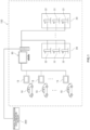
- FIG. 1 is a conceptual diagram illustrating a power system apparatus disclosed herein.
- a power system apparatus 100 disclosed herein is an apparatus that manages charge and discharge (herein referred to as "charge/discharge”) of electric vehicles 10, in order to contribute to stabilizing the power supply/demand balance of a power transmission/distribution facility 200.
- the power system apparatus 100 includes a power storage device that stores power, although not illustrated.
- the power system apparatus 100 manages supply (herein “charge”) of power stored in the power storage device to the electric vehicles 10 and supply (herein “discharge") of power from the electric vehicles 10 to the power storage device.
- the power supplied to the power storage device may be sold to a particular power company etc. Meanwhile, the power stored in the power storage device can be bought by users of the electric vehicles 10.
- the power system apparatus 100 may be an apparatus that is used to sell and buy power.
- the power system apparatus 100 is implemented by a client server system, for example. However, the power system apparatus 100 may be implemented through cloud computing.
- the electric vehicles 10 are vehicles that use electricity as an energy source.
- the electric vehicles 10 are a type of transport devices, and may be four-wheeled vehicles or may be two-wheeled vehicles.
- the electric vehicles 10 may be battery electric vehicles (BEVs) that include a storage battery as a drive source, or may be hybrid electric vehicles (HEVs) that include a storage battery and an internal combustion engine as drive sources.
- BEVs battery electric vehicles
- HEVs hybrid electric vehicles
- the term "hybrid electric vehicles” as used herein includes plug-in hybrid electric vehicles (PHEVs) that include a charge device that supplies power from a stationary power source to the storage battery.
- the electric vehicles 10 preferably include a control device (electronic control unit: ECU) for an electric system that can measure the state of charge (SOC) of the storage battery etc.
- ECU electronic control unit
- the ECU manages various states of the storage battery mounted on the vehicle.
- the ECU includes a voltage sensor, a current sensor, a temperature sensor, etc. (not illustrated) in order to manage the states of the storage battery.
- the ECU receives and stores an inter-terminal voltage input from the voltage sensor, a charge/discharge current input from the current sensor, a battery temperature input from the temperature sensor, etc. as signals that are necessary to manage the storage battery, for example.
- the ECU can measure the SOC of the storage battery of the electric vehicle 10 on the basis of the input signals.
- user terminals 15 should be configured to be able to bidirectionally communicate with a resource aggregator 30.
- the user terminals 15 may be car navigation systems mounted on the electric vehicles 10, or smartphones, tablet terminals, or desktop or laptop personal computers that are used by users, for example.
- Charge/discharge devices 22 are devices that can be electrically connected to the electric vehicles 10 to charge and discharge the electric vehicles 10.
- the charge/discharge devices 22 are installed at charge/discharge spots 20.
- the number of charge/discharge devices 22 installed at a single charge/discharge spot 20 is not specifically limited. That is, one or a plurality of charge/discharge devices 22 are installed at a single charge/discharge spot 20.
- the charge/discharge spots 20 are each managed by a predetermined management device (not illustrated). That is, one or a plurality of charge/discharge devices 22 installed at a single charge/discharge spot 20 are managed by the single management device.
- the charge/discharge spots 20 may be parking lots in which the charge/discharge devices 22 are installed, for example.
- the parking lots are not specifically limited, and may be parking lots for a shop that sells products, parking lots for a shop that provides a service such as a beauty salon, parking lots for large-scale commercial facilities, parking lots for
- the resource aggregator 30 herein manages the power system apparatus 100.
- the resource aggregator 30 is connected to the user terminals 15, the power transmission/distribution facility 200, and the charge/discharge devices 22 so as to be able to bidirectionally communicate therewith, and collectively manages information obtained from the user terminals 15, the power transmission/distribution facility 200, and the charge/discharge devices 22.
- the resource aggregator 30 may be implemented by a single computer, or may be jointly implemented by a plurality of computers.
- the resource aggregator 30 controls the supply/demand amount of power so as to keep the power supply/demand balance at the power transmission/distribution facility 200.
- the resource aggregator 30 procures and supplies power in accordance with a power supply request from the power transmission/distribution facility 200, for example.
- the resource aggregator 30 demands power in accordance with a power demand request from the power transmission/distribution facility 200.
- the power system apparatus 100 has one or a plurality of users that use or own the electric vehicle 10 as registered therein, and one or a plurality of charge/discharge devices 22 that charge and discharge the electric vehicle 10 as registered therein.
- the power system apparatus 100 may have the electric vehicles 10 themselves as registered therein.
- the power system apparatus 100 manages power by supplying (herein "charging”) power from the charge/discharge devices 22 to the electric vehicles 10 and supplying (herein “discharging”) power from the electric vehicles 10 to the charge/discharge devices 22.
- the power transmission/distribution facility 200 is a facility that supplies power, which is supplied from power plants that can supply power to the power transmission/distribution facility 200, to power consuming facilities.
- power plants as used herein may refer to facilities that include power generating equipment known in the art, such as thermal power plants, wind power plants, hydraulic power plants, atomic power plants, and photovoltaic power plants, for example.
- power consuming facilities may refer to facilities such as houses, commercial facilities, factories, and schools, for example.
- FIG. 2 is a block diagram illustrating the resource aggregator 30 etc.
- the resource aggregator 30 includes a control device 35.
- the configuration of the control device 35 is not specifically limited.
- the control device 35 includes a read only memory (ROM) that stores a program for control, a central processing unit (CPU) that can execute the program, a random access memory (RAM) that is used as a working area for developing the program, a storage device such as a memory that stores the program and various kinds of data, and input/output ports.
- ROM read only memory
- CPU central processing unit
- RAM random access memory
- the control device 35 of the power system apparatus 100 disclosed herein includes a power supply/demand information acquisition unit 51, a charge/discharge management unit 52, a first calculator 53, a second calculator 54, a rank setting unit 55, and an incentive management unit 56.
- the control device 35 also includes, in addition to the units 51 to 56, a storage 40, a first communication unit 41, a second communication unit 42, a third communication unit 43, a vehicle information acquisition unit 57, a selector 58, and a point imparting unit 59.
- the various units 40 to 58 that constitute the control device 35 may be implemented by one or a plurality of processors, or may be incorporated in a circuit.
- the first communication unit 41 is configured to be able to communicate with the power transmission/distribution facility 200.
- the power transmission/distribution facility 200 includes a controller 210 that can communicate with at least the first communication unit 41.
- the first communication unit 41 is connected to be able to communicate with the controller 210 of the power transmission/distribution facility 200, for example.
- the controller 210 stores in advance power supply/demand information D1 on the power transmission/distribution facility 200.
- the power supply/demand information D1 is information about the power supply/demand balance of the power transmission/distribution facility 200.
- the power supply/demand information D1 includes at least a predicted power demand amount and a predicted power supply amount at the power transmission/distribution facility 200.
- the predicted power demand amount is a predicted value of the amount of power to be supplied from the power transmission/distribution facility 200 to the power consuming facilities discussed above.
- the predicted power supply amount is a predicted value of the amount of power to be supplied from the power plants discussed above to the power transmission/distribution facility 200.
- the second communication unit 42 is configured to be able to communicate with the user terminal 15 of a user that uses (owns) the electric vehicle 10.
- the second communication unit 42 is an example of the communication unit of the power system apparatus disclosed herein.
- the user terminal 15 includes a screen 16, an input unit 17 that is operated by the user to make an input such as a touch screen, a keyboard, and a mouse, and a terminal controller 18.
- the terminal controller 18 is connected to be able to communicate with the screen 16 and the input unit 17.
- the second communication unit 42 is connected to be able to communicate with the terminal controller 18 of the user terminal 15.
- the user terminal 15 stores in advance vehicle information D2 on the electric vehicle 10.
- the user terminal 15 may be configured to transmit the vehicle information D2 to the resource aggregator 30 at predetermined intervals.
- the vehicle information D2 is information about the electric vehicle 10 that is used by the user.
- the vehicle information D2 may include the state of charge (SOC) of the electric vehicle 10, information on the present position of the electric vehicle 10, an expected travel distance of the electric vehicle 10, etc., for example.
- the third communication unit 43 is configured to be able to communicate with the charge/discharge device 22 installed at the charge/discharge spot 20.
- the charge/discharge device 22 includes an identification (ID) information detector 23, a charge/discharge amount measurement unit 24, and a device controller 25.
- the device controller 25 is connected to be able to communicate with the ID information detector 23 and the charge/discharge amount measurement unit 24.
- the third communication unit 43 is connected to be able to communicate with the device controller 25 of the charge/discharge device 22.
- the ID information detector 23 acquires a vehicle ID of the electric vehicle 10 electrically connected to the charge/discharge device 22 to be charged or discharged and a user ID of the user that uses (owns) the electric vehicle 10 (hereinafter collectively referred to as "ID information").
- the charge/discharge amount measurement unit 24 measures the amount of power (charge/discharge amount) by which the electric vehicle 10 electrically connected to the charge/discharge device 22 is charged or discharged.
- the amount of power (charge amount) by which the electric vehicle 10 is charged means the amount of power supplied from the power transmission/distribution facility 200 to the electric vehicle 10.
- the amount of power (discharge amount) discharged from the electric vehicle 10 means the amount of power supplied from the electric vehicle 10 to the power transmission/distribution facility 200.
- the device controller 25 stores the acquired ID information and the charge/discharge amount in association with each other as charge/discharge information D3.
- the charge/discharge information D3 may include, in addition to the above information, information such as the ID of the charge/discharge device 22 that has performed charge or discharge and the ID of the charge/discharge spot 20 at which the charge/discharge device 22 is installed, for example.
- the power supply/demand information acquisition unit 51 acquires the power supply/demand information D1 discussed above.
- the power supply/demand information D1 is stored in advance in the controller 210 of the power transmission/distribution facility 200. Therefore, the power supply/demand information acquisition unit 51 acquires the power supply/demand information D1 via the first communication unit 41.
- the vehicle information acquisition unit 57 acquires the vehicle information D2 discussed above.
- the vehicle information D2 is stored in advance in the terminal controller 18 of the user terminal 15. Therefore, the vehicle information acquisition unit 57 acquires the vehicle information D2 via the second communication unit 42.
- the charge/discharge management unit 52 manages the charge/discharge amount of the electric vehicle 10 electrically connected to the charge/discharge device 22 to be charged or discharged.
- the charge/discharge management unit 52 may be configured to receive a charge/discharge signal transmitted when the electric vehicle 10 is electrically connected to the charge/discharge device 22 to start and end charge or discharge. Consequently, the resource aggregator 30 can confirm that charge or discharge has been performed between the charge/discharge device 22 and the electric vehicle 10, and grasp the charge/discharge amount of the electric vehicle 10.
- the first calculator 53 calculates an urgency degree or a redundancy degree on the basis of the power supply/demand information D1 acquired by the power supply/demand information acquisition unit 51, and calculates a first rank point based on the urgency degree or the redundancy degree.
- the urgency degree and the redundancy degree will be described. As illustrated in FIG. 3 , the urgency degree and the redundancy degree are calculated from a predicted power demand amount A at X hours later and a predicted power supply amount B at X hours later. Specifically, the urgency degree and the redundancy degree can be calculated using a formula (predicted power demand amount at X hours later - predicted power supply amount at X hours later)/X, for example.
- the predicted power demand amount is more than the predicted power supply amount, it is predicted that power will be short at the power transmission/distribution facility 200.
- the predicted power supply amount is more than the predicted power demand amount, on the other hand, it is predicted that power will be redundant at the power transmission/distribution facility 200.
- the first calculator 53 is configured to calculate an urgency degree when the predicted power demand amount is more than the predicted power supply amount, and to calculate a redundancy degree when the predicted power supply amount is more than the predicted power demand amount.
- the first calculator 53 is configured to then calculate a first rank point on the basis of the urgency degree or the redundancy degree. A user that desires to gain as high a first rank point as possible is expected to participate in the power supply/demand adjustment at the timing when charge or discharge is needed.
- the first calculator 53 is preferably configured to calculate a higher first rank point as the urgency degree or the redundancy degree is higher. Consequently, it is possible to promote the user of the electric vehicle 10 to participate in the power supply/demand adjustment adequately at the timing when the power supply/demand adjustment is needed.
- the first calculator 53 is preferably configured to calculate a first rank point on the basis of a first rate when the predicted power demand amount more than the predicted power supply amount and the urgency degree is calculated.
- the first calculator 53 is preferably configured to calculate a first rank point on the basis of a second rate, which is lower than the first rate, when the predicted power supply amount more than the predicted power demand amount and a redundancy degree is calculated.
- the first rate and the second rate are each a coefficient that is used to calculate a first rank point. A higher first rank point is calculated as the rate is higher. That is, in the configuration discussed above, the first calculator 53 is configured to calculate a high first rank point in the case where an urgency degree is calculated compared to the case where a redundancy degree is calculated.
- a particularly high first rank point is calculated when the urgency degree is high.
- the user of the electric vehicle 10 can be promoted to participate in the power supply/demand adjustment more suitably when the urgency degree is particularly high. Consequently, it is possible to suitably secure users that participate in the power supply/demand adjustment when the urgency degree is particularly high.
- the second communication unit 42 is configured to transmit, to the user terminal 15, a charge/discharge request notification that includes at least information about the calculated first rank point.
- the charge/discharge request notification is a notification that requests the user of the electric vehicle 10 to charge or discharge the charge/discharge device 22.
- the user of the electric vehicle 10 can determine whether or not to charge or discharge the charge/discharge device 22 using his/her own electric vehicle 10, by confirming the charge/discharge request notification presented to his/her own user terminal 15.
- the charge/discharge request notification may include, besides information about the first rank point, which of charge and discharge is requested, the position of the charge/discharge spot 20 that can be used, information on roads to the charge/discharge spot 20, information on the power selling and buying prices, etc.
- the expression "charge/discharge spot 20 that can be used” refers to the charge/discharge device 22 installed at the charge/discharge spot 20 that is not being used.
- the second calculator 54 is configured to calculate a second rank point on the basis of the charge/discharge amount acquired by the charge/discharge management unit 52.
- the second rank point is calculated on the basis of the amount of power that is actually supplied (discharged) or demanded (charged) when the electric vehicle 10 is electrically connected to the charge/discharge device 22. That is, the second rank point is a point imparted to the user that has performed charge or discharge at the timing when charge or discharge is needed.
- the first and second rank points are elements that constitute setting of a rank to be discussed later, and are points to be imparted to each user.
- the first rank point is calculated on the basis of the urgency degree or the redundancy degree.
- the second rank point is calculated on the basis of the charge/discharge amount.
- the first rank point which is based on the urgency degree or the redundancy degree, can prompt the user to participate in the power supply/demand adjustment at the timing when charge or discharge is needed.
- the second rank point which is based on the charge/discharge amount, can reflect a substantial degree of contribution.
- the rank setting unit 55 is configured to set a rank on the basis of the first rank point calculated by the first calculator 53 and the second rank point calculated by the second calculator 54.
- the rank is set in association with the vehicle ID or the user ID.
- the rank is an index that indicates a cooperative electric vehicle or user that positively participates in the power supply/demand adjustment at the timing when the power supply/demand adjustment is necessary.
- the rank is preferably set in accordance with the total of the first rank point and the second rank point for a period since a predetermined timing until the present. While the rank (hereinafter referred to as "user rank”) set in association with the user ID is described as an example, it is not intended to specifically limit the technology disclosed herein.
- the user rank set by the rank setting unit 55 is managed by the database DB1.
- the database DB1 is stored in advance in the storage 40.
- the user of the electric vehicle 10 that transmitted a charge/discharge signal to the charge/discharge management unit 52 and the user rank set by the rank setting unit 55 are saved in association with each other in the database DB1.
- the user rank is saved in the database DB1.
- FIG. 4 is a table indicating an example of the database DB1 stored in the storage 40.
- the database DB1 stores the vehicle ID, the user ID, the first rank point, the second rank point, the imparted point, the accumulated point, and the user rank in correlation with each other, for example.
- the vehicle ID stores identification information on the electric vehicle 10 charged or discharged using the charge/discharge device 22.
- the user ID stores identification information on the user that uses the electric vehicle 10. In the case where the user uses (owns) a plurality of electric vehicles 10 and has the plurality of electric vehicles 10 charged or discharged, a plurality of vehicle IDs may be registered for a single user ID.
- the first rank point stores a first rank point calculated by the first calculator 53 on the basis of the urgency degree or the redundancy degree.
- the second rank point stores a second rank point calculated by the second calculator 54 on the basis of the charge/discharge amount.
- the imparted point stores the total of the first and second rank points.
- the accumulated point stores the total of the first and second rank points imparted to the user since a predetermined timing until the present.
- the user rank stores a rank set by the rank setting unit 55 on the basis of the accumulated point. While a case where a user possesses a plurality of vehicles and a rank is set for each user has been described above, a rank may be set for each vehicle.
- the incentive management unit 56 is configured to calculate an incentive to be imparted to the user that transmitted a charge/discharge signal to the charge/discharge management unit 52 on the basis of the rank set by the rank setting unit 55. Specifically, the incentive management unit 56 is configured to set a higher incentive to the user of the electric vehicle 10 at a higher rank with reference to the database DB1.
- the incentive is not specifically limited as long as the incentive can be adjusted for each user and promotes the user to participate in the power supply/demand adjustment.
- the incentive may be money, a coupon, a complimentary ticket, a discount on the electricity charge, etc., for example.
- the coupon may be a coupon that increases the rate at which the user will be paid when power is discharged from the electric vehicle 10, or may be a coupon that reduces the rate at which the user will pay when the electric vehicle 10 is charged, for example.
- the selector 58 selects a transmission destination for the charge/discharge request notification discussed above.
- the second communication unit 42 transmits a charge/discharge request notification to the transmission destination selected by the selector 58.
- the selector 58 may select a transmission destination on the basis of the vehicle information D2 acquired by the vehicle information acquisition unit 57, for example. Alternatively, the selector 58 may select a transmission destination on the basis of the rank.
- a first rank point based on an urgency degree or a redundancy degree and a second rank point based on a substantial charge/discharge amount are calculated, and a rank is set on the basis of the first and second rank points. Then, an incentive based on the rank is calculated and imparted. Consequently, it is surmised that a user that desires to gain a higher incentive performs more charge or discharge when the urgency degree or the redundancy degree is higher. Therefore, the resource aggregator 30 can secure more users that positively participate in the power supply/demand adjustment at the timing when the power supply/demand adjustment is necessary.
- the power system apparatus 100 with such a configuration, it is possible to adjust the power supply/demand balance of the power transmission/distribution facility 200 more suitably.
- FIGS. 5 and 6 are each a sequence diagram illustrating a power supply/demand adjustment process performed in order to adjust the power supply/demand balance at the power transmission/distribution facility 200 using the electric vehicle 10.
- FIG. 5 illustrates a process for a case where the predicted power demand amount is more than the predicted power supply amount.
- FIG. 6 illustrates a process for a case where the predicted power supply amount is more than the predicted power demand amount.
- the resource aggregator 30 receives power supply/demand information D1 from the power transmission/distribution facility 200 (S1).
- the resource aggregator 30 calculates an urgency degree or a redundancy degree on the basis of the power supply/demand information D1, and calculates a first rank point on the basis of the urgency degree or the redundancy degree (S2).
- a redundancy degree is calculated in step S2 as illustrated in FIG. 6
- power is supplied from the power transmission/distribution facility 200.
- the resource aggregator 30 transmits a charge/discharge request notification to the user terminal 15 of the user that uses the electric vehicle 10 (S3).
- the charge/discharge request notification includes at least information about the calculated first rank point.
- the user of the electric vehicle 10 that accepts a charge/discharge request after confirming the charge/discharge request notification electrically connects the electric vehicle 10 that the user himself/herself uses to the charge/discharge device 22.
- the resource aggregator 30 confirms that charge or discharge has been performed (S4).
- the resource aggregator 30 acquires the charge amount or the discharge amount between the electric vehicle 10 and the charge/discharge device 22 (S5).
- the resource aggregator 30 supplies power based on the discharge amount to the power transmission/distribution facility 200.
- the resource aggregator 30 calculates a second rank point on the basis of the acquired charge/discharge amount (S5).
- the resource aggregator 30 sets a rank on the basis of the calculated first rank point and second rank point (S6). Finally, the resource aggregator 30 calculates an incentive to be imparted to the user of the electric vehicle 10 on the basis of the rank (S7).
- the power supply/demand adjustment is implemented using the electric vehicle 10 by performing such processes.
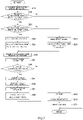
- FIG. 7 is a flowchart of the power supply/demand adjustment disclosed herein.
- the power system apparatus 100 disclosed herein performs steps S1 to S7 in FIGS. 5 and 6 as follows.
- Step S10 in FIG. 7 is performed in S1 in FIGS. 5 and 6 .
- the power supply/demand information acquisition unit 51 in FIG. 2 acquires power supply/demand information D1 from the power transmission/distribution facility 200.
- the power supply/demand information D1 to be acquired is information about the power supply/demand balance at the power transmission/distribution facility 200 as discussed above, and includes at least a predicted power demand amount and a predicted power supply amount at the power transmission/distribution facility 200.
- Steps S20 to S25 in FIG. 7 are performed in S2 in FIGS. 5 and 6 .
- steps S20 to S23 an urgency degree or a redundancy degree is calculated on the basis of the power supply/demand information D1 acquired in step S10.
- steps S24 and S25 a first rank point is calculated on the basis of the calculated urgency degree or redundancy degree.
- step S20 the first calculator 53 in FIG. 2 determines whether or not the predicted power demand amount and the predicted power supply amount acquired by the power supply/demand information acquisition unit 51 disagree with each other. In the case where the predicted power demand amount and the predicted power supply amount disagree with each other (step S20: YES), the process proceeds to step S21. In the case where the predicted power demand amount and the predicted power supply amount are equal to each other, the process is ended, since the power supply/demand balance is good and it is not necessary to perform the power supply/demand adjustment process based on the urgency degree or the redundancy degree.
- step S21 the first calculator 53 in FIG. 2 determines whether or not the predicted power demand amount acquired by the power supply/demand information acquisition unit 51 is more than the predicted power supply amount. In the case where the predicted power demand amount is more than the predicted power supply amount (step S21: YES), the process proceeds to step S22.
- step S22 the first calculator 53 calculates an urgency degree.
- step S24 the first calculator 53 calculates a first rank point on the basis of the first rate.
- the first rank point is preferably calculated in accordance with how high the urgency degree is.
- the first rank point may be calculated on the basis of the product of the urgency degree and the first rate, although the present disclosure is not specifically limited thereto.
- step S23 the first calculator 53 calculates a redundancy degree.
- step S25 the first calculator 53 calculates a first rank point on the basis of the second rate which is lower than the first rate.
- the first rank point is preferably calculated so as to be higher as the redundancy degree is higher.
- the first rank point may be calculated on the basis of the product of the redundancy degree and the second rate, although the present disclosure is not specifically limited thereto.
- a high first rank point is calculated in the case where an urgency degree is calculated compared to the case where a redundancy degree is calculated as discussed above.
- a particularly high first rank point is calculated when the urgency degree is high.
- Steps S30 and S31 in FIG. 7 are performed in S3 in FIGS. 5 and 6 .
- the second communication unit 42 in FIG. 2 transmits a charge/discharge request notification on the basis of an instruction from the first calculator 53.
- the charge/discharge request notification to be transmitted includes at least information about the first rank point.
- the charge/discharge request notification is transmitted to the user terminal 15 via the second communication unit 42.
- the transmitted charge/discharge request notification is preferably configured to be displayed on the screen 16 of the user terminal 15. Specifically, at least information about the first rank point may be presented to the user of the electric vehicle 10, for example. At this time, a list of the charge/discharge spots 20 that can be used, the distances from the present position of the user to the charge/discharge spots 20, etc. may be displayed. The list may have a function of rearranging the charge/discharge spots 20 in the order of the distance etc. When the user has determined the charge/discharge spot 20 at which charge or discharge is to be performed, a route to the determined charge/discharge spot 20 may be indicated. The user terminal 15 may have a function of providing guidance on the route to the charge/discharge spot 20.
- the user In the case where the user accepts a charge/discharge request after confirming the presented charge/discharge request notification, the user transmits the vehicle information D2 on the electric vehicle 10 and the user ID of the user himself/herself from the user terminal 15 to the resource aggregator 30 by operating the input unit 17. At this time, additional information such as the charge/discharge spot 20 at which the user performs charge or discharge and the charge/discharge amount desired by the user may be transmitted in association with the vehicle information D2 etc.
- step S31 the vehicle information acquisition unit 57 receives the vehicle information D2 transmitted from the user terminal 15 via the second communication unit 42.
- step S30 the selector 58 in FIG. 2 selects electric vehicles or users sequentially in the descending order of the rank as the transmission destination for the charge/discharge request notification, and instructs the second communication unit 42 to transmit the charge/discharge request notification to the user terminal 15 at the selected transmission destination.
- the selector 58 in FIG. 2 selects electric vehicles or users sequentially in the descending order of the rank as the transmission destination for the charge/discharge request notification, and instructs the second communication unit 42 to transmit the charge/discharge request notification to the user terminal 15 at the selected transmission destination.
- the selector 58 may select a transmission destination for the charge/discharge request notification with reference to the vehicle information D2 acquired by the vehicle information acquisition unit 57.
- the electric vehicles 10 that are positioned in the vicinity of the charge/discharge spot 20 that can be used may be sequentially selected as the transmission destination.
- the electric vehicles 10 in a high state of charge (SOC) may be preferentially selected as the transmission destination.
- the electric vehicles 10 in a low state of charge may be preferentially selected as the transmission destination.
- Steps S40 and S41 in FIG. 7 are performed in S4 in FIGS. 5 and 6 .
- step S40 it is determined whether or not the charge/discharge management unit 52 in FIG. 2 has received a charge/discharge start signal.
- the user confirms the presented charge/discharge request notification, and drives the electric vehicle 10 to the charge/discharge spot 20.
- the electric vehicle 10 is electrically connected to the charge/discharge device 22 to start charge or discharge.
- a charge/discharge start signal is transmitted from the charge/discharge device 22 to the charge/discharge management unit 52 via the third communication unit 43.
- step S40 It can be determined that charge or discharge has been started when the charge/discharge management unit 52 receives the charge/discharge start signal.
- the process proceeds to step S41.
- the resource aggregator 30 does not receive the charge/discharge start signal even after the lapse of a predetermined time (step S40: NO)
- the power demand/supply process is ended.
- the predetermined time is not specifically limited, but may be set as appropriate to about 30 minutes to 10 hours after the charge/discharge request notification is transmitted in step S30.
- step S41 it is determined that charge or discharge has been ended when the charge/discharge management unit 52 receives the charge/discharge end signal.
- Steps S50 to S52 in FIG. 7 are performed in S5 in FIGS. 5 and 6 .
- the second calculator 54 in FIG. 2 acquires a charge/discharge amount measured by the charge/discharge amount measurement unit 24 of the charge/discharge device 22.
- the charge/discharge amount is stored in the device controller 25 of the charge/discharge device 22 in FIG. 2 in association with the ID information on the electric vehicle 10 and the user of the vehicle acquired by the ID information detector 23. Therefore, the second calculator 54 acquires a charge/discharge amount associated with ID information via the second communication unit 42.
- step S51 the second calculator 54 in FIG. 2 calculates a second rank point on the basis of the charge/discharge amount of the electric vehicle 10 electrically connected to the charge/discharge device 22.
- the second rank point is preferably calculated so as to be higher as the charge/discharge amount is larger.
- a higher second rank point is calculated for a user that has substantially contributed to the power supply/demand adjustment by charging or discharging more power. Consequently, it is expected that users with large charge/discharge amounts positively participate in the power supply/demand adjustment, and the power supply/demand balance at the power transmission/distribution facility 200 can be stabilized more immediately.
- step S52 the point imparting unit 59 in FIG. 2 imparts the first rank point calculated by the first calculator 53 and the second rank point calculated by the second calculator 54 to the user.
- the phrase "imparting the first and second rank points to the user" indicates that the first and second rank points are registered for the user with the user ID and the first and second rank points associated with each other in the database DB1 stored in the storage 40, for example.
- Step S60 in FIG. 7 is performed in S6 in FIGS. 5 and 6 .
- the rank setting unit 55 in FIG. 2 sets a rank on the basis of the first rank point calculated by the first calculator 53 and the second rank point calculated by the second calculator 54.
- the rank setting unit 55 references the database DB1 stored in the storage 40 such as that illustrated in FIG. 4 , and sets a user rank on the basis of the accumulated point of the first and second rank points registered in association with the user ID of the user of the electric vehicle 10 that has performed charge or discharge. Then, a user rank associated with the user ID in the database DB1 is preferably updated.
- the resource aggregator 30 can secure more users that may participate in the power supply/demand adjustment. Therefore, the power supply/demand balance can be adjusted more suitably.
- Steps S70 and S71 in FIG. 7 are performed in S7 in FIGS. 5 and 6 .
- the incentive management unit 56 in FIG. 2 calculates an incentive to be imparted to the user of the electric vehicle 10 on the basis of the rank set by the rank setting unit 55.
- the incentive management unit 56 references the database DB1 stored in the storage 40, and calculates an incentive to be imparted on the basis of the rank registered in association with the user ID of the user of the electric vehicle 10 that has performed charge or discharge.
- the incentive management unit 56 is configured to calculate a higher incentive as the rank is higher.
- step S71 the incentive management unit 56 in FIG. 2 imparts the calculated incentive to the user.
- the phrase "imparting an incentive” indicates that a user ID and an incentive are associated with each other in the database DB1 stored in the storage 40 to register the incentive for the user, for example.
- the incentive may be imparted by transmitting the electronic coupon etc. to the user terminal 15.
- each of the degree of cooperation of the user in the power supply/demand adjustment and the substantial degree of contribution can be calculated as a rank point by the first calculator 53 calculating a first rank point based on the urgency degree or the redundancy degree and the second calculator 54 calculating a second rank point based on the actual charge/discharge amount. Consequently, even a user of the electric vehicle 10 that can charge or discharge a substantially small amount of power can have a motivation to participate in the power supply/demand adjustment. There is a merit in positively participating in the power supply/demand adjustment, as the user of the electric vehicle 10 can raise his/her own rank by gaining more rank points by positively participating in the power supply/demand adjustment when the urgency degree or the redundancy degree is high.
- the resource aggregator 30 can adjust the power supply/demand balance more suitably, as an appropriate charge/discharge amount can be obtained at a necessary timing when charge or discharge of power is requested by the power transmission/distribution facility 200.
Landscapes
- Engineering & Computer Science (AREA)
- Power Engineering (AREA)
- Transportation (AREA)
- Mechanical Engineering (AREA)
- Life Sciences & Earth Sciences (AREA)
- Sustainable Development (AREA)
- Sustainable Energy (AREA)
- Physics & Mathematics (AREA)
- General Physics & Mathematics (AREA)
- Charge And Discharge Circuits For Batteries Or The Like (AREA)
- Supply And Distribution Of Alternating Current (AREA)
- Management, Administration, Business Operations System, And Electronic Commerce (AREA)
Abstract
A power system apparatus that suitably secures users of electric vehicles performing charge/discharge at the timing when power supply/demand adjustment is needed is provided. The power system apparatus disclosed herein includes: a power supply/demand information acquisition unit; a first calculator configured to calculate an urgency degree or a redundancy degree and a first rank point; a communication unit; a charge/discharge management unit; a second calculator configured to acquire a charge/discharge amount and calculate a second rank point; a rank setting unit configured to set a rank based on the first rank point calculated by the first calculator and the second rank point calculated by the second calculator; and an incentive management unit configured to calculate an incentive.
Description
- The technology disclosed herein relates to a power system apparatus and a power supply/demand adjustment method in which the power system apparatus is used.
- In recent years, there has been proposed a power supply/demand adjustment method in which general users cooperate in the adjustment of the power supply/demand balance at a power transmission/distribution facility managed by a power company, etc., and are given a certain incentive (such as money and points) in return. In the power supply/demand adjustment method, a power supply/demand request is sent to users that have a large storage battery that can be charged and discharged repeatedly when the power supply/demand balance is lost at the power transmission/distribution facility. When accepting the request, a user connects a storage battery thereof to a power supply/demand management device, etc., to exchange power between the storage battery and the power transmission/distribution facility via the power supply/demand management device. Then, the power supply/demand management device imparts an incentive to the user in accordance with the amount of power exchanged.
- An example of the power supply/demand management device discussed above is disclosed in
Japanese Patent Application Publication No. 2020-42686 Japanese Patent Application Publication No. 2020-42686 -
Japanese Patent No. 5529894 - In the technologies described in
Japanese Patent Application Publication No. 2020-42686 Japanese Patent No. 5529894 - The present disclosure has been made in view of such circumstances, and therefore has an object to provide a power system apparatus that suitably secures users of electric vehicles performing charge and discharge at the timing when the power supply/demand adjustment is needed. Another object is to provide a power supply/demand adjustment method in which the power system apparatus is used.
- In order to achieve the above object, the technology disclosed herein provides the following power system apparatus. The power system apparatus disclosed herein includes a power supply/demand information acquisition unit, a first calculator, a communication unit, a charge/discharge management unit, a second calculator, a rank setting unit, and an incentive management unit. The power supply/demand information acquisition unit is configured to acquire power supply/demand information from a power transmission/distribution facility. The first calculator is configured to calculate an urgency degree or a redundancy degree on the basis of the power supply/demand information, and calculate a first rank point on the basis of the urgency degree or the redundancy degree. The communication unit is configured to transmit, to a user of an electric vehicle, a charge/discharge request notification that includes at least information about the calculated first rank point. The charge/discharge management unit is configured to manage a charge/discharge amount of the electric vehicle. The second calculator is configured to acquire the charge/discharge amount on the basis of data ascertained by the charge/discharge management unit, and calculate a second rank point on the basis of the charge/discharge amount. The rank setting unit is configured to set a rank based on the first rank point calculated by the first calculator and the second rank point calculated by the second calculator. The incentive management unit is configured to calculate an incentive to be imparted to the user of the electric vehicle on the basis of the rank set by the rank setting unit.
- In the power system apparatus configured as discussed above, a first rank point and a second rank point are calculated, and a rank based on the rank points is set. Then, an incentive to be imparted to the user of the electric vehicle is calculated on the basis of the rank. The rank is an index that indicates a cooperative electric vehicle or user that positively participates in the power supply/demand adjustment at the timing when the power supply/demand adjustment is necessary. The first rank point is a point calculated on the basis of the urgency degree or the redundancy degree. In other words, the first rank point is a point that prompts the user to cooperate in the power supply/demand adjustment at the timing when the power supply/demand adjustment is necessary. The second rank point is a point calculated on the basis of the charge/discharge amount. In other words, the second rank point is calculated as a point to be imparted to the user that actually performs charge or discharge at the timing when the power supply/demand adjustment is necessary. With such a configuration, the user of the electric vehicle can gain an incentive that matches his/her rank (i.e., whether or not the user is cooperative in the power supply/demand adjustment at a necessary timing). Consequently, it is possible to suitably secure users of electric vehicles that positively perform charge or discharge at the timing when the power supply/demand adjustment is necessary.
- In an aspect of the power system apparatus disclosed herein, the first calculator may be configured to calculate a higher first rank point as the urgency degree or the redundancy degree is higher.
- With such a configuration, a higher first rank point is calculated for users that positively cooperate when the urgency degree or the redundancy degree is high. Consequently, it is possible to suitably secure users of electric vehicles that perform charge or discharge at the timing when the power supply/demand adjustment is necessary.
- In an aspect of the power system apparatus disclosed herein, the power supply/demand information acquired by the power supply/demand information acquisition unit may include at least a predicted power demand amount and a predicted power supply amount. The first calculator may be configured to calculate the urgency degree and calculate the first rank point on the basis of a first rate in the case where the predicted power demand amount is more than the predicted power supply amount. The first calculator may be configured to calculate the redundancy degree and calculate the first rank point on the basis of a second rate, which is lower than the first rate, in the case where the predicted power supply amount is more than the predicted power demand amount.
- With such a configuration, a particularly high first rank point is calculated in the case where the predicted power demand amount is more than the predicted power supply amount, that is, in the case where an urgency degree is calculated. Consequently, it is possible to prompt more users of electric vehicles to participate in the power supply/demand adjustment when the urgency degree is high.
- In an aspect of the power system apparatus disclosed herein, the power system apparatus may further include a selector configured to select a transmission destination for the charge/discharge request notification. The selector may be configured to select users of electric vehicles for transmission destination for the charge/discharge request notification sequentially in a descending order of the rank.
- With such a configuration, information about charge and discharge is preferentially transmitted to users of electric vehicles that cooperate by positively performing charge or discharge at the timing when the power supply/demand adjustment is necessary. Consequently, it is possible to preferentially guide users that are highly likely to perform charge or discharge at the timing when the power supply/demand adjustment is necessary to the charge/discharge device. Therefore, it is possible to immediately stabilize the power supply/demand balance.
- Another aspect provides a power supply/demand adjustment method disclosed herein. The power supply/demand adjustment method disclosed herein is a power supply/demand adjustment method of adjusting a power supply/demand balance at a power transmission/distribution facility using an electric vehicle. The power supply/demand adjustment method includes: acquiring power supply/demand information from the power transmission/distribution facility; calculating an urgency degree or a redundancy degree on the basis of the power supply/demand information; calculating a first rank point on the basis of the calculated urgency degree or redundancy degree; transmitting, to a user of the electric vehicle, a charge/discharge request notification that includes at least the first rank point; managing a charge/discharge state of the electric vehicle using a charge/discharge management unit; acquiring a charge/discharge amount of the electric vehicle on the basis of the managed charge/discharge state; calculating a second rank point on the basis of the charge/discharge amount; setting a rank on the basis of the calculated first rank point and second rank point; and calculating an incentive to be imparted to the user of the electric vehicle on the basis of the rank.
- With such a configuration, a rank is set on the basis of the first rank point calculated on the basis of the urgency degree or the redundancy degree and the second rank point calculated on the basis of the charge/discharge amount. Then, an incentive is imparted on the basis of the rank. That is, users of electric vehicles that positively participate in the power supply/demand adjustment at the timing when the power supply/demand adjustment is necessary can gain an incentive that matches their ranks. Consequently, it is possible to secure users of electric vehicles that positively perform charge or discharge at the timing when the power supply/demand adjustment is necessary.
- In an aspect of the power supply/demand adjustment method disclosed herein, in the step of calculating the first rank point, the first rank point may be calculated so as to be higher as the urgency degree or the redundancy degree calculated on the basis of the power supply/demand information is higher.
- With such a configuration, a higher first rank point is calculated for users that perform charge or discharge when the urgency degree or the redundancy degree is high, that is, at the timing when the power supply/demand adjustment is needed. Consequently, it is possible to effectively prompt users to participate in the power supply/demand adjustment at the timing when the power supply/demand adjustment is needed.
- In an aspect of the power supply/demand adjustment method disclosed herein, the power supply/demand information acquired in the acquiring the power supply/demand information may include at least a predicted power demand amount and a predicted power supply amount; in the step of calculating the urgency degree or the redundancy degree, in the case where the predicted power demand amount is more than the predicted power supply amount, the urgency degree may be calculated; and in the step of calculating the urgency degree or the redundancy degree, in the case where the predicted power supply amount is more than the predicted power demand amount, the redundancy degree may be calculated. In another aspect, in the case where the urgency degree is calculated, the first rank point may be calculated on the basis of a first rate, in the step of calculating the first rank point; and in the case where the redundancy degree is calculated, the first rank point may be calculated on the basis of a second rate, which is lower than the first rate, in the step of calculating the first rank point.
- With such a configuration, a particularly high first rank point can be calculated for users that perform charge or discharge when the urgency degree is high. Consequently, it is possible to particularly prompt users to supply power to the power transmission/distribution facility when the urgency degree is high, that is, when the predicted power demand amount is more than the predicted power supply amount and a power shortage is predicted.
- In an aspect of the power supply/demand adjustment method disclosed herein, the method may further include selecting a transmission destination for the charge/discharge request notification, and users of electric vehicles may be selected for transmission destination for the charge/discharge request notification sequentially in a descending order of the rank.
- With such a configuration, it is possible to preferentially guide users of electric vehicles that positively perform charge or discharge at the timing when the power supply/demand adjustment is necessary to the charge/discharge device. Consequently, it is possible to immediately stabilize the power supply/demand balance.
-
-
FIG. 1 is a conceptual diagram illustrating a power system apparatus according to an embodiment; -
FIG. 2 is a block diagram illustrating a resource aggregator, a power transmission/distribution facility, a user terminal, and a charge/discharge device according to the embodiment; -
FIG. 3 illustrates calculation of an urgency degree or a redundancy degree of the power system apparatus according to the embodiment; -
FIG. 4 is a table indicating an example of a database stored in a storage; -
FIG. 5 is a sequence diagram illustrating an example of process procedures by the power system apparatus according to the embodiment; -
FIG. 6 is a sequence diagram illustrating another example of the process procedures by the power system apparatus according to the embodiment; and -
FIG. 7 is a flowchart illustrating the process procedures by the power system apparatus according to the embodiment. - A power system apparatus according to an embodiment disclosed herein will be described below with reference to the drawings. Matters that are not mentioned herein but are necessary to implement the present disclosure may be grasped as design matters for a person skilled in the art based on the related art in the relevant field. The embodiment described herein is not intended to specifically limit the present disclosure as a matter of course. The present disclosure is not limited to the embodiment described herein unless specifically stated otherwise. Members and portions that achieve the same effect are denoted by the same reference numerals as appropriate to omit redundant description as appropriate.
-
FIG. 1 is a conceptual diagram illustrating a power system apparatus disclosed herein. Apower system apparatus 100 disclosed herein is an apparatus that manages charge and discharge (herein referred to as "charge/discharge") ofelectric vehicles 10, in order to contribute to stabilizing the power supply/demand balance of a power transmission/distribution facility 200. Thepower system apparatus 100 includes a power storage device that stores power, although not illustrated. Thepower system apparatus 100 manages supply (herein "charge") of power stored in the power storage device to theelectric vehicles 10 and supply (herein "discharge") of power from theelectric vehicles 10 to the power storage device. The power supplied to the power storage device may be sold to a particular power company etc. Meanwhile, the power stored in the power storage device can be bought by users of theelectric vehicles 10. Thepower system apparatus 100 may be an apparatus that is used to sell and buy power. - The
power system apparatus 100 is implemented by a client server system, for example. However, thepower system apparatus 100 may be implemented through cloud computing. - The
electric vehicles 10 are vehicles that use electricity as an energy source. Theelectric vehicles 10 are a type of transport devices, and may be four-wheeled vehicles or may be two-wheeled vehicles. Theelectric vehicles 10 may be battery electric vehicles (BEVs) that include a storage battery as a drive source, or may be hybrid electric vehicles (HEVs) that include a storage battery and an internal combustion engine as drive sources. The term "hybrid electric vehicles" as used herein includes plug-in hybrid electric vehicles (PHEVs) that include a charge device that supplies power from a stationary power source to the storage battery. Theelectric vehicles 10 preferably include a control device (electronic control unit: ECU) for an electric system that can measure the state of charge (SOC) of the storage battery etc. - The ECU manages various states of the storage battery mounted on the vehicle. The ECU includes a voltage sensor, a current sensor, a temperature sensor, etc. (not illustrated) in order to manage the states of the storage battery. The ECU receives and stores an inter-terminal voltage input from the voltage sensor, a charge/discharge current input from the current sensor, a battery temperature input from the temperature sensor, etc. as signals that are necessary to manage the storage battery, for example. The ECU can measure the SOC of the storage battery of the
electric vehicle 10 on the basis of the input signals. - It is only necessary that
user terminals 15 should be configured to be able to bidirectionally communicate with aresource aggregator 30. Theuser terminals 15 may be car navigation systems mounted on theelectric vehicles 10, or smartphones, tablet terminals, or desktop or laptop personal computers that are used by users, for example. - Charge/
discharge devices 22 are devices that can be electrically connected to theelectric vehicles 10 to charge and discharge theelectric vehicles 10. The charge/discharge devices 22 are installed at charge/discharge spots 20. The number of charge/discharge devices 22 installed at a single charge/discharge spot 20 is not specifically limited. That is, one or a plurality of charge/discharge devices 22 are installed at a single charge/discharge spot 20. The charge/discharge spots 20 are each managed by a predetermined management device (not illustrated). That is, one or a plurality of charge/discharge devices 22 installed at a single charge/discharge spot 20 are managed by the single management device. The charge/discharge spots 20 may be parking lots in which the charge/discharge devices 22 are installed, for example. The parking lots are not specifically limited, and may be parking lots for a shop that sells products, parking lots for a shop that provides a service such as a beauty salon, parking lots for large-scale commercial facilities, parking lots for a house, etc., for example. - The
resource aggregator 30 herein manages thepower system apparatus 100. Theresource aggregator 30 is connected to theuser terminals 15, the power transmission/distribution facility 200, and the charge/discharge devices 22 so as to be able to bidirectionally communicate therewith, and collectively manages information obtained from theuser terminals 15, the power transmission/distribution facility 200, and the charge/discharge devices 22. Theresource aggregator 30 may be implemented by a single computer, or may be jointly implemented by a plurality of computers. - The
resource aggregator 30 controls the supply/demand amount of power so as to keep the power supply/demand balance at the power transmission/distribution facility 200. Theresource aggregator 30 procures and supplies power in accordance with a power supply request from the power transmission/distribution facility 200, for example. Alternatively, theresource aggregator 30 demands power in accordance with a power demand request from the power transmission/distribution facility 200. For example, thepower system apparatus 100 has one or a plurality of users that use or own theelectric vehicle 10 as registered therein, and one or a plurality of charge/discharge devices 22 that charge and discharge theelectric vehicle 10 as registered therein. Thepower system apparatus 100 may have theelectric vehicles 10 themselves as registered therein. Thepower system apparatus 100 manages power by supplying (herein "charging") power from the charge/discharge devices 22 to theelectric vehicles 10 and supplying (herein "discharging") power from theelectric vehicles 10 to the charge/discharge devices 22. - The power transmission/
distribution facility 200 is a facility that supplies power, which is supplied from power plants that can supply power to the power transmission/distribution facility 200, to power consuming facilities. The term "power plants" as used herein may refer to facilities that include power generating equipment known in the art, such as thermal power plants, wind power plants, hydraulic power plants, atomic power plants, and photovoltaic power plants, for example. The term "power consuming facilities" may refer to facilities such as houses, commercial facilities, factories, and schools, for example. - Next, an example of a specific configuration of the
power system apparatus 100 disclosed herein will be described.FIG. 2 is a block diagram illustrating theresource aggregator 30 etc. As illustrated inFIG. 2 , theresource aggregator 30 includes acontrol device 35. The configuration of thecontrol device 35 is not specifically limited. Thecontrol device 35 includes a read only memory (ROM) that stores a program for control, a central processing unit (CPU) that can execute the program, a random access memory (RAM) that is used as a working area for developing the program, a storage device such as a memory that stores the program and various kinds of data, and input/output ports. - The
control device 35 of thepower system apparatus 100 disclosed herein includes a power supply/demandinformation acquisition unit 51, a charge/discharge management unit 52, afirst calculator 53, asecond calculator 54, arank setting unit 55, and anincentive management unit 56. Thecontrol device 35 also includes, in addition to theunits 51 to 56, astorage 40, afirst communication unit 41, asecond communication unit 42, athird communication unit 43, a vehicleinformation acquisition unit 57, aselector 58, and apoint imparting unit 59. Thevarious units 40 to 58 that constitute thecontrol device 35 may be implemented by one or a plurality of processors, or may be incorporated in a circuit. - The
first communication unit 41 is configured to be able to communicate with the power transmission/distribution facility 200. The power transmission/distribution facility 200 includes acontroller 210 that can communicate with at least thefirst communication unit 41. Thefirst communication unit 41 is connected to be able to communicate with thecontroller 210 of the power transmission/distribution facility 200, for example. - The
controller 210 stores in advance power supply/demand information D1 on the power transmission/distribution facility 200. The power supply/demand information D1 is information about the power supply/demand balance of the power transmission/distribution facility 200. The power supply/demand information D1 includes at least a predicted power demand amount and a predicted power supply amount at the power transmission/distribution facility 200. The predicted power demand amount is a predicted value of the amount of power to be supplied from the power transmission/distribution facility 200 to the power consuming facilities discussed above. The predicted power supply amount is a predicted value of the amount of power to be supplied from the power plants discussed above to the power transmission/distribution facility 200. - The
second communication unit 42 is configured to be able to communicate with theuser terminal 15 of a user that uses (owns) theelectric vehicle 10. Thesecond communication unit 42 is an example of the communication unit of the power system apparatus disclosed herein. As illustrated inFIG. 2 , theuser terminal 15 includes ascreen 16, an input unit 17 that is operated by the user to make an input such as a touch screen, a keyboard, and a mouse, and aterminal controller 18. Theterminal controller 18 is connected to be able to communicate with thescreen 16 and the input unit 17. Thesecond communication unit 42 is connected to be able to communicate with theterminal controller 18 of theuser terminal 15. - The
user terminal 15 stores in advance vehicle information D2 on theelectric vehicle 10. Theuser terminal 15 may be configured to transmit the vehicle information D2 to theresource aggregator 30 at predetermined intervals. The vehicle information D2 is information about theelectric vehicle 10 that is used by the user. The vehicle information D2 may include the state of charge (SOC) of theelectric vehicle 10, information on the present position of theelectric vehicle 10, an expected travel distance of theelectric vehicle 10, etc., for example. - The
third communication unit 43 is configured to be able to communicate with the charge/discharge device 22 installed at the charge/discharge spot 20. The charge/discharge device 22 includes an identification (ID)information detector 23, a charge/dischargeamount measurement unit 24, and adevice controller 25. Thedevice controller 25 is connected to be able to communicate with theID information detector 23 and the charge/dischargeamount measurement unit 24. Thethird communication unit 43 is connected to be able to communicate with thedevice controller 25 of the charge/discharge device 22. - The
ID information detector 23 acquires a vehicle ID of theelectric vehicle 10 electrically connected to the charge/discharge device 22 to be charged or discharged and a user ID of the user that uses (owns) the electric vehicle 10 (hereinafter collectively referred to as "ID information"). The charge/dischargeamount measurement unit 24 measures the amount of power (charge/discharge amount) by which theelectric vehicle 10 electrically connected to the charge/discharge device 22 is charged or discharged. The amount of power (charge amount) by which theelectric vehicle 10 is charged means the amount of power supplied from the power transmission/distribution facility 200 to theelectric vehicle 10. Meanwhile, the amount of power (discharge amount) discharged from theelectric vehicle 10 means the amount of power supplied from theelectric vehicle 10 to the power transmission/distribution facility 200. - The
device controller 25 stores the acquired ID information and the charge/discharge amount in association with each other as charge/discharge information D3. The charge/discharge information D3 may include, in addition to the above information, information such as the ID of the charge/discharge device 22 that has performed charge or discharge and the ID of the charge/discharge spot 20 at which the charge/discharge device 22 is installed, for example. - The power supply/demand
information acquisition unit 51 acquires the power supply/demand information D1 discussed above. The power supply/demand information D1 is stored in advance in thecontroller 210 of the power transmission/distribution facility 200. Therefore, the power supply/demandinformation acquisition unit 51 acquires the power supply/demand information D1 via thefirst communication unit 41. - The vehicle
information acquisition unit 57 acquires the vehicle information D2 discussed above. The vehicle information D2 is stored in advance in theterminal controller 18 of theuser terminal 15. Therefore, the vehicleinformation acquisition unit 57 acquires the vehicle information D2 via thesecond communication unit 42. - The charge/
discharge management unit 52 manages the charge/discharge amount of theelectric vehicle 10 electrically connected to the charge/discharge device 22 to be charged or discharged. For example, the charge/discharge management unit 52 may be configured to receive a charge/discharge signal transmitted when theelectric vehicle 10 is electrically connected to the charge/discharge device 22 to start and end charge or discharge. Consequently, theresource aggregator 30 can confirm that charge or discharge has been performed between the charge/discharge device 22 and theelectric vehicle 10, and grasp the charge/discharge amount of theelectric vehicle 10. - The
first calculator 53 calculates an urgency degree or a redundancy degree on the basis of the power supply/demand information D1 acquired by the power supply/demandinformation acquisition unit 51, and calculates a first rank point based on the urgency degree or the redundancy degree. The urgency degree and the redundancy degree will be described. As illustrated inFIG. 3 , the urgency degree and the redundancy degree are calculated from a predicted power demand amount A at X hours later and a predicted power supply amount B at X hours later. Specifically, the urgency degree and the redundancy degree can be calculated using a formula (predicted power demand amount at X hours later - predicted power supply amount at X hours later)/X, for example. When the predicted power demand amount is more than the predicted power supply amount, it is predicted that power will be short at the power transmission/distribution facility 200. When the predicted power supply amount is more than the predicted power demand amount, on the other hand, it is predicted that power will be redundant at the power transmission/distribution facility 200. - In the
power system apparatus 100 according to an aspect disclosed herein, thefirst calculator 53 is configured to calculate an urgency degree when the predicted power demand amount is more than the predicted power supply amount, and to calculate a redundancy degree when the predicted power supply amount is more than the predicted power demand amount. Thefirst calculator 53 is configured to then calculate a first rank point on the basis of the urgency degree or the redundancy degree. A user that desires to gain as high a first rank point as possible is expected to participate in the power supply/demand adjustment at the timing when charge or discharge is needed. - When the urgency degree or the redundancy degree calculated by the
first calculator 53 is high, it may be desired to immediately stabilize the power supply/demand balance at the power transmission/distribution facility 200. Thus, thefirst calculator 53 is preferably configured to calculate a higher first rank point as the urgency degree or the redundancy degree is higher. Consequently, it is possible to promote the user of theelectric vehicle 10 to participate in the power supply/demand adjustment adequately at the timing when the power supply/demand adjustment is needed. - The
first calculator 53 is preferably configured to calculate a first rank point on the basis of a first rate when the predicted power demand amount more than the predicted power supply amount and the urgency degree is calculated. In addition, thefirst calculator 53 is preferably configured to calculate a first rank point on the basis of a second rate, which is lower than the first rate, when the predicted power supply amount more than the predicted power demand amount and a redundancy degree is calculated. The first rate and the second rate are each a coefficient that is used to calculate a first rank point. A higher first rank point is calculated as the rate is higher. That is, in the configuration discussed above, thefirst calculator 53 is configured to calculate a high first rank point in the case where an urgency degree is calculated compared to the case where a redundancy degree is calculated. With such a configuration, a particularly high first rank point is calculated when the urgency degree is high. Thus, the user of theelectric vehicle 10 can be promoted to participate in the power supply/demand adjustment more suitably when the urgency degree is particularly high. Consequently, it is possible to suitably secure users that participate in the power supply/demand adjustment when the urgency degree is particularly high. - The
second communication unit 42 is configured to transmit, to theuser terminal 15, a charge/discharge request notification that includes at least information about the calculated first rank point. The charge/discharge request notification is a notification that requests the user of theelectric vehicle 10 to charge or discharge the charge/discharge device 22. The user of theelectric vehicle 10 can determine whether or not to charge or discharge the charge/discharge device 22 using his/her ownelectric vehicle 10, by confirming the charge/discharge request notification presented to his/herown user terminal 15. The charge/discharge request notification may include, besides information about the first rank point, which of charge and discharge is requested, the position of the charge/discharge spot 20 that can be used, information on roads to the charge/discharge spot 20, information on the power selling and buying prices, etc. The expression "charge/discharge spot 20 that can be used" refers to the charge/discharge device 22 installed at the charge/discharge spot 20 that is not being used. - The
second calculator 54 is configured to calculate a second rank point on the basis of the charge/discharge amount acquired by the charge/discharge management unit 52. The second rank point is calculated on the basis of the amount of power that is actually supplied (discharged) or demanded (charged) when theelectric vehicle 10 is electrically connected to the charge/discharge device 22. That is, the second rank point is a point imparted to the user that has performed charge or discharge at the timing when charge or discharge is needed. - The first and second rank points are elements that constitute setting of a rank to be discussed later, and are points to be imparted to each user. The first rank point is calculated on the basis of the urgency degree or the redundancy degree. The second rank point is calculated on the basis of the charge/discharge amount. The first rank point, which is based on the urgency degree or the redundancy degree, can prompt the user to participate in the power supply/demand adjustment at the timing when charge or discharge is needed. The second rank point, which is based on the charge/discharge amount, can reflect a substantial degree of contribution. By calculating the first and second rank points in this manner, an appropriate charge/discharge amount can be obtained at the timing when charge or discharge is necessary.
- The
rank setting unit 55 is configured to set a rank on the basis of the first rank point calculated by thefirst calculator 53 and the second rank point calculated by thesecond calculator 54. The rank is set in association with the vehicle ID or the user ID. The rank is an index that indicates a cooperative electric vehicle or user that positively participates in the power supply/demand adjustment at the timing when the power supply/demand adjustment is necessary. The rank is preferably set in accordance with the total of the first rank point and the second rank point for a period since a predetermined timing until the present. While the rank (hereinafter referred to as "user rank") set in association with the user ID is described as an example, it is not intended to specifically limit the technology disclosed herein. - The user rank set by the
rank setting unit 55 is managed by the database DB1. The database DB1 is stored in advance in thestorage 40. The user of theelectric vehicle 10 that transmitted a charge/discharge signal to the charge/discharge management unit 52 and the user rank set by therank setting unit 55 are saved in association with each other in the database DB1. When a user rank is set by therank setting unit 55 in step S60 inFIG. 7 , the user rank is saved in the database DB1. -
FIG. 4 is a table indicating an example of the database DB1 stored in thestorage 40. The database DB1 stores the vehicle ID, the user ID, the first rank point, the second rank point, the imparted point, the accumulated point, and the user rank in correlation with each other, for example. - The vehicle ID stores identification information on the
electric vehicle 10 charged or discharged using the charge/discharge device 22. The user ID stores identification information on the user that uses theelectric vehicle 10. In the case where the user uses (owns) a plurality ofelectric vehicles 10 and has the plurality ofelectric vehicles 10 charged or discharged, a plurality of vehicle IDs may be registered for a single user ID. The first rank point stores a first rank point calculated by thefirst calculator 53 on the basis of the urgency degree or the redundancy degree. The second rank point stores a second rank point calculated by thesecond calculator 54 on the basis of the charge/discharge amount. The imparted point stores the total of the first and second rank points. The accumulated point stores the total of the first and second rank points imparted to the user since a predetermined timing until the present. The user rank stores a rank set by therank setting unit 55 on the basis of the accumulated point. While a case where a user possesses a plurality of vehicles and a rank is set for each user has been described above, a rank may be set for each vehicle. - The
incentive management unit 56 is configured to calculate an incentive to be imparted to the user that transmitted a charge/discharge signal to the charge/discharge management unit 52 on the basis of the rank set by therank setting unit 55. Specifically, theincentive management unit 56 is configured to set a higher incentive to the user of theelectric vehicle 10 at a higher rank with reference to the database DB1. - The incentive is not specifically limited as long as the incentive can be adjusted for each user and promotes the user to participate in the power supply/demand adjustment. The incentive may be money, a coupon, a complimentary ticket, a discount on the electricity charge, etc., for example. Specifically, the coupon may be a coupon that increases the rate at which the user will be paid when power is discharged from the
electric vehicle 10, or may be a coupon that reduces the rate at which the user will pay when theelectric vehicle 10 is charged, for example. By imparting an incentive that matches the rank, the user of theelectric vehicle 10 is surmised to positively perform charge or discharge when the urgency degree or the redundancy degree is high, in order to reach a higher rank. - The
selector 58 selects a transmission destination for the charge/discharge request notification discussed above. Thesecond communication unit 42 transmits a charge/discharge request notification to the transmission destination selected by theselector 58. Theselector 58 may select a transmission destination on the basis of the vehicle information D2 acquired by the vehicleinformation acquisition unit 57, for example. Alternatively, theselector 58 may select a transmission destination on the basis of the rank. - In the
power system apparatus 100 configured as discussed above, a first rank point based on an urgency degree or a redundancy degree and a second rank point based on a substantial charge/discharge amount are calculated, and a rank is set on the basis of the first and second rank points. Then, an incentive based on the rank is calculated and imparted. Consequently, it is surmised that a user that desires to gain a higher incentive performs more charge or discharge when the urgency degree or the redundancy degree is higher. Therefore, theresource aggregator 30 can secure more users that positively participate in the power supply/demand adjustment at the timing when the power supply/demand adjustment is necessary. Thus, with thepower system apparatus 100 with such a configuration, it is possible to adjust the power supply/demand balance of the power transmission/distribution facility 200 more suitably. - Then, a power supply/demand adjustment process to be performed with the constitutions illustrated in
FIGS. 1 and2 will be described.FIGS. 5 and6 are each a sequence diagram illustrating a power supply/demand adjustment process performed in order to adjust the power supply/demand balance at the power transmission/distribution facility 200 using theelectric vehicle 10.FIG. 5 illustrates a process for a case where the predicted power demand amount is more than the predicted power supply amount.FIG. 6 illustrates a process for a case where the predicted power supply amount is more than the predicted power demand amount. - As illustrated in
FIGS. 5 and6 , theresource aggregator 30 receives power supply/demand information D1 from the power transmission/distribution facility 200 (S1). Theresource aggregator 30 calculates an urgency degree or a redundancy degree on the basis of the power supply/demand information D1, and calculates a first rank point on the basis of the urgency degree or the redundancy degree (S2). In the case where a redundancy degree is calculated in step S2 as illustrated inFIG. 6 , power is supplied from the power transmission/distribution facility 200. Then, theresource aggregator 30 transmits a charge/discharge request notification to theuser terminal 15 of the user that uses the electric vehicle 10 (S3). The charge/discharge request notification includes at least information about the calculated first rank point. The user of theelectric vehicle 10 that accepts a charge/discharge request after confirming the charge/discharge request notification electrically connects theelectric vehicle 10 that the user himself/herself uses to the charge/discharge device 22. Theresource aggregator 30 confirms that charge or discharge has been performed (S4). In addition, theresource aggregator 30 acquires the charge amount or the discharge amount between theelectric vehicle 10 and the charge/discharge device 22 (S5). In the case where discharge is confirmed as illustrated inFIG. 5 , theresource aggregator 30 supplies power based on the discharge amount to the power transmission/distribution facility 200. Theresource aggregator 30 calculates a second rank point on the basis of the acquired charge/discharge amount (S5). Then, theresource aggregator 30 sets a rank on the basis of the calculated first rank point and second rank point (S6). Finally, theresource aggregator 30 calculates an incentive to be imparted to the user of theelectric vehicle 10 on the basis of the rank (S7). The power supply/demand adjustment is implemented using theelectric vehicle 10 by performing such processes. - Then, steps S1 to S7 in
FIGS. 5 and6 discussed above will be described in more detail with reference toFIG. 7. FIG. 7 is a flowchart of the power supply/demand adjustment disclosed herein. In order to perform the power supply/demand adjustment according to the urgency degree or the redundancy degree, thepower system apparatus 100 disclosed herein performs steps S1 to S7 inFIGS. 5 and6 as follows. - Step S10 in
FIG. 7 is performed in S1 inFIGS. 5 and6 . In step S10, the power supply/demandinformation acquisition unit 51 inFIG. 2 acquires power supply/demand information D1 from the power transmission/distribution facility 200. The power supply/demand information D1 to be acquired is information about the power supply/demand balance at the power transmission/distribution facility 200 as discussed above, and includes at least a predicted power demand amount and a predicted power supply amount at the power transmission/distribution facility 200. - Steps S20 to S25 in
FIG. 7 are performed in S2 inFIGS. 5 and6 . In steps S20 to S23, an urgency degree or a redundancy degree is calculated on the basis of the power supply/demand information D1 acquired in step S10. In steps S24 and S25, a first rank point is calculated on the basis of the calculated urgency degree or redundancy degree. - In step S20, the
first calculator 53 inFIG. 2 determines whether or not the predicted power demand amount and the predicted power supply amount acquired by the power supply/demandinformation acquisition unit 51 disagree with each other. In the case where the predicted power demand amount and the predicted power supply amount disagree with each other (step S20: YES), the process proceeds to step S21. In the case where the predicted power demand amount and the predicted power supply amount are equal to each other, the process is ended, since the power supply/demand balance is good and it is not necessary to perform the power supply/demand adjustment process based on the urgency degree or the redundancy degree. - In step S21, the
first calculator 53 inFIG. 2 determines whether or not the predicted power demand amount acquired by the power supply/demandinformation acquisition unit 51 is more than the predicted power supply amount. In the case where the predicted power demand amount is more than the predicted power supply amount (step S21: YES), the process proceeds to step S22. In step S22, thefirst calculator 53 calculates an urgency degree. Then, in step S24, thefirst calculator 53 calculates a first rank point on the basis of the first rate. The first rank point is preferably calculated in accordance with how high the urgency degree is. The first rank point may be calculated on the basis of the product of the urgency degree and the first rate, although the present disclosure is not specifically limited thereto. - In the case where the predicted power demand amount is not more than the predicted power supply amount (step S21: NO), on the other hand, the process proceeds to step S23. In step S23, the
first calculator 53 calculates a redundancy degree. Then, in step S25, thefirst calculator 53 calculates a first rank point on the basis of the second rate which is lower than the first rate. The first rank point is preferably calculated so as to be higher as the redundancy degree is higher. The first rank point may be calculated on the basis of the product of the redundancy degree and the second rate, although the present disclosure is not specifically limited thereto. - In the power supply/demand adjustment method according to the aspect disclosed herein, a high first rank point is calculated in the case where an urgency degree is calculated compared to the case where a redundancy degree is calculated as discussed above. With such a configuration, a particularly high first rank point is calculated when the urgency degree is high. Thus, the user of the
electric vehicle 10 can be promoted to participate in the power supply/demand adjustment more adequately when the urgency degree is particularly high. - Steps S30 and S31 in
FIG. 7 are performed in S3 inFIGS. 5 and6 . In step S30, thesecond communication unit 42 inFIG. 2 transmits a charge/discharge request notification on the basis of an instruction from thefirst calculator 53. The charge/discharge request notification to be transmitted includes at least information about the first rank point. The charge/discharge request notification is transmitted to theuser terminal 15 via thesecond communication unit 42. - The transmitted charge/discharge request notification is preferably configured to be displayed on the
screen 16 of theuser terminal 15. Specifically, at least information about the first rank point may be presented to the user of theelectric vehicle 10, for example. At this time, a list of the charge/discharge spots 20 that can be used, the distances from the present position of the user to the charge/discharge spots 20, etc. may be displayed. The list may have a function of rearranging the charge/discharge spots 20 in the order of the distance etc. When the user has determined the charge/discharge spot 20 at which charge or discharge is to be performed, a route to the determined charge/discharge spot 20 may be indicated. Theuser terminal 15 may have a function of providing guidance on the route to the charge/discharge spot 20. - In the case where the user accepts a charge/discharge request after confirming the presented charge/discharge request notification, the user transmits the vehicle information D2 on the
electric vehicle 10 and the user ID of the user himself/herself from theuser terminal 15 to theresource aggregator 30 by operating the input unit 17. At this time, additional information such as the charge/discharge spot 20 at which the user performs charge or discharge and the charge/discharge amount desired by the user may be transmitted in association with the vehicle information D2 etc. - In step S31, the vehicle
information acquisition unit 57 receives the vehicle information D2 transmitted from theuser terminal 15 via thesecond communication unit 42. - In a suitable aspect, in step S30, the
selector 58 inFIG. 2 selects electric vehicles or users sequentially in the descending order of the rank as the transmission destination for the charge/discharge request notification, and instructs thesecond communication unit 42 to transmit the charge/discharge request notification to theuser terminal 15 at the selected transmission destination. With such a configuration, users of electric vehicles that are expected to positively contribute to the power supply/demand adjustment can be preferentially guided to the charge/discharge spot 20. Consequently, it is possible to stabilize the power supply/demand balance more suitably. - In step S30, the
selector 58 may select a transmission destination for the charge/discharge request notification with reference to the vehicle information D2 acquired by the vehicleinformation acquisition unit 57. For example, theelectric vehicles 10 that are positioned in the vicinity of the charge/discharge spot 20 that can be used may be sequentially selected as the transmission destination. In the case where an urgency degree is calculated, theelectric vehicles 10 in a high state of charge (SOC) may be preferentially selected as the transmission destination. In the case where a redundancy degree is calculated, on the other hand, theelectric vehicles 10 in a low state of charge may be preferentially selected as the transmission destination. - Steps S40 and S41 in
FIG. 7 are performed in S4 inFIGS. 5 and6 . In step S40, it is determined whether or not the charge/discharge management unit 52 inFIG. 2 has received a charge/discharge start signal. The user confirms the presented charge/discharge request notification, and drives theelectric vehicle 10 to the charge/discharge spot 20. When the charge/discharge spot 20 is reached, theelectric vehicle 10 is electrically connected to the charge/discharge device 22 to start charge or discharge. When the charge/discharge device 22 and theelectric vehicle 10 are electrically connected to each other to start charge or discharge, a charge/discharge start signal is transmitted from the charge/discharge device 22 to the charge/discharge management unit 52 via thethird communication unit 43. It can be determined that charge or discharge has been started when the charge/discharge management unit 52 receives the charge/discharge start signal. In the case where theresource aggregator 30 receives the charge/discharge start signal (step S40: YES), the process proceeds to step S41. In the case where theresource aggregator 30 does not receive the charge/discharge start signal even after the lapse of a predetermined time (step S40: NO), the power demand/supply process is ended. The predetermined time is not specifically limited, but may be set as appropriate to about 30 minutes to 10 hours after the charge/discharge request notification is transmitted in step S30. - Then, when charge or discharge is ended, a charge/discharge end signal is transmitted from the charge/
discharge device 22 to the charge/discharge management unit 52 via thethird communication unit 43. In step S41, it is determined that charge or discharge has been ended when the charge/discharge management unit 52 receives the charge/discharge end signal. - Steps S50 to S52 in
FIG. 7 are performed in S5 inFIGS. 5 and6 . In step S50, thesecond calculator 54 inFIG. 2 acquires a charge/discharge amount measured by the charge/dischargeamount measurement unit 24 of the charge/discharge device 22. The charge/discharge amount is stored in thedevice controller 25 of the charge/discharge device 22 inFIG. 2 in association with the ID information on theelectric vehicle 10 and the user of the vehicle acquired by theID information detector 23. Therefore, thesecond calculator 54 acquires a charge/discharge amount associated with ID information via thesecond communication unit 42. - In step S51, the
second calculator 54 inFIG. 2 calculates a second rank point on the basis of the charge/discharge amount of theelectric vehicle 10 electrically connected to the charge/discharge device 22. The second rank point is preferably calculated so as to be higher as the charge/discharge amount is larger. With such a configuration, a higher second rank point is calculated for a user that has substantially contributed to the power supply/demand adjustment by charging or discharging more power. Consequently, it is expected that users with large charge/discharge amounts positively participate in the power supply/demand adjustment, and the power supply/demand balance at the power transmission/distribution facility 200 can be stabilized more immediately. - In step S52, the
point imparting unit 59 inFIG. 2 imparts the first rank point calculated by thefirst calculator 53 and the second rank point calculated by thesecond calculator 54 to the user. The phrase "imparting the first and second rank points to the user" indicates that the first and second rank points are registered for the user with the user ID and the first and second rank points associated with each other in the database DB1 stored in thestorage 40, for example. - Step S60 in
FIG. 7 is performed in S6 inFIGS. 5 and6 . In step S60, therank setting unit 55 inFIG. 2 sets a rank on the basis of the first rank point calculated by thefirst calculator 53 and the second rank point calculated by thesecond calculator 54. By way of example, therank setting unit 55 references the database DB1 stored in thestorage 40 such as that illustrated inFIG. 4 , and sets a user rank on the basis of the accumulated point of the first and second rank points registered in association with the user ID of the user of theelectric vehicle 10 that has performed charge or discharge. Then, a user rank associated with the user ID in the database DB1 is preferably updated. With such a configuration, it is possible to set a user rank in consideration of each of the degree of cooperation of the user in the power supply/demand adjustment and the substantial degree of contribution. Consequently, even a user of theelectric vehicle 10 that can charge or discharge a substantially small amount of power can have a motivation to participate in the power supply/demand adjustment. Theresource aggregator 30 can secure more users that may participate in the power supply/demand adjustment. Therefore, the power supply/demand balance can be adjusted more suitably. - Steps S70 and S71 in
FIG. 7 are performed in S7 inFIGS. 5 and6 . In step S70, theincentive management unit 56 inFIG. 2 calculates an incentive to be imparted to the user of theelectric vehicle 10 on the basis of the rank set by therank setting unit 55. Theincentive management unit 56 references the database DB1 stored in thestorage 40, and calculates an incentive to be imparted on the basis of the rank registered in association with the user ID of the user of theelectric vehicle 10 that has performed charge or discharge. Typically, theincentive management unit 56 is configured to calculate a higher incentive as the rank is higher. - Then, in step S71, the
incentive management unit 56 inFIG. 2 imparts the calculated incentive to the user. The phrase "imparting an incentive" indicates that a user ID and an incentive are associated with each other in the database DB1 stored in thestorage 40 to register the incentive for the user, for example. In the case where the incentive is something that is electronically exchangeable, e.g. an electronic coupon etc., for example, the incentive may be imparted by transmitting the electronic coupon etc. to theuser terminal 15. - As discussed above, each of the degree of cooperation of the user in the power supply/demand adjustment and the substantial degree of contribution can be calculated as a rank point by the
first calculator 53 calculating a first rank point based on the urgency degree or the redundancy degree and thesecond calculator 54 calculating a second rank point based on the actual charge/discharge amount. Consequently, even a user of theelectric vehicle 10 that can charge or discharge a substantially small amount of power can have a motivation to participate in the power supply/demand adjustment. There is a merit in positively participating in the power supply/demand adjustment, as the user of theelectric vehicle 10 can raise his/her own rank by gaining more rank points by positively participating in the power supply/demand adjustment when the urgency degree or the redundancy degree is high. With such a configuration, meanwhile, theresource aggregator 30 can adjust the power supply/demand balance more suitably, as an appropriate charge/discharge amount can be obtained at a necessary timing when charge or discharge of power is requested by the power transmission/distribution facility 200. - While a specific example of the present disclosure has been described in detail above, this is merely exemplary, and does not limit the scope of the claims. The technology described in the claims includes various alterations and modifications of the specific example indicated above.
Claims (9)
- A power system apparatus (100) comprising:a power supply/demand information acquisition unit (51) configured to acquire power supply/demand information from a power transmission/distribution facility (200);a first calculator (53) configured to calculate an urgency degree or a redundancy degree on the basis of the power supply/demand information, and calculate a first rank point on the basis of the urgency degree or the redundancy degree;a communication unit configured to transmit, to a user of an electric vehicle (10), a charge/discharge request notification that includes at least information about the calculated first rank point;a charge/discharge management unit (52) configured to manage a charge/discharge amount of the electric vehicle (10);a second calculator (54) configured to acquire the charge/discharge amount on the basis of data ascertained by the charge/discharge management unit (52), and calculate a second rank point on the basis of the charge/discharge amount;a rank setting unit (55) configured to set a rank based on the first rank point calculated by the first calculator (53) and the second rank point calculated by the second calculator (54); andan incentive management unit (56) configured to calculate an incentive to be imparted to the user of the electric vehicle (10) on the basis of the rank set by the rank setting unit (55).
- The power system apparatus (100) according to claim 1, wherein
the first calculator (53) is configured to calculate a higher first rank point as the urgency degree or the redundancy degree is higher. - The power system apparatus (100) according to claim 1 or 2, whereinthe power supply/demand information acquired by the power supply/demand information acquisition unit (51) includes at least a predicted power demand amount and a predicted power supply amount;the first calculator (53) is configured to calculate the urgency degree and calculate the first rank point on the basis of a first rate in the case where the predicted power demand amount is more than the predicted power supply amount; andthe first calculator (53) is configured to calculate the redundancy degree and calculate the first rank point on the basis of a second rate, which is lower than the first rate, in the case where the predicted power supply amount is more than the predicted power demand amount.
- The power system apparatus (100) according to any one of claims 1 to 3, further comprisinga selector (58) configured to select a transmission destination for the charge/discharge request notification, whereinthe selector (58) is configured to select users of electric vehicles (10) for transmission destination for the charge/discharge request notification sequentially in a descending order of the rank set by the rank setting unit (55).
- A power supply/demand adjustment method of adjusting a power supply/demand balance at a power transmission/distribution facility (200) using an electric vehicle (10), the method comprising:acquiring power supply/demand information from the power transmission/distribution facility (200);calculating an urgency degree or a redundancy degree on the basis of the power supply/demand information;calculating a first rank point on the basis of the calculated urgency degree or redundancy degree;transmitting, to a user of the electric vehicle, a charge/discharge request notification that includes at least the first rank point;managing a charge/discharge state of the electric vehicle (10) using a charge/discharge management unit (52);acquiring a charge/discharge amount of the electric vehicle (10) on the basis of the managed charge/discharge state;calculating a second rank point on the basis of the charge/discharge amount;setting a rank on the basis of the calculated first rank point and second rank point; andcalculating an incentive to be imparted to the user of the electric vehicle (10) on the basis of the rank.
- The power supply/demand adjustment method according to claim 5, wherein
in the step of calculating the first rank point, the first rank point is calculated so as to be higher as the urgency degree or the redundancy degree calculated on the basis of the power supply/demand information is higher. - The power supply/demand adjustment method according to claim 5 or 6, whereinthe power supply/demand information acquired in the acquiring the power supply/demand information includes at least a predicted power demand amount and a predicted power supply amount;in the step of calculating the urgency degree or the redundancy degree, in the case where the predicted power demand amount is more than the predicted power supply amount, the urgency degree is calculated; andin the step of calculating the urgency degree or the redundancy degree, in the case where the predicted power supply amount is more than the predicted power demand amount, the redundancy degree is calculated.
- The power supply/demand adjustment method according to claim 7, whereinin the case where the urgency degree is calculated, the first rank point on the basis of a first rate is calculated in the step of calculating the first rank point; andin the case where the redundancy degree is calculated, the first rank point on the basis of a second rate, which is lower than the first rate, is calculated in the step of calculating the first rank point.
- The power supply/demand adjustment method according to any one of claims 5 to 8, further comprisingselecting a transmission destination for the charge/discharge request notification, whereinusers of electric vehicles (10) are selected for transmission destination for the charge/discharge request notification sequentially in a descending order of the rank.
Applications Claiming Priority (1)
| Application Number | Priority Date | Filing Date | Title |
|---|---|---|---|
| JP2021152473A JP7443305B2 (en) | 2021-09-17 | 2021-09-17 | power grid system |
Publications (1)
| Publication Number | Publication Date |
|---|---|
| EP4151456A1 true EP4151456A1 (en) | 2023-03-22 |
Family
ID=83270824
Family Applications (1)
| Application Number | Title | Priority Date | Filing Date |
|---|---|---|---|
| EP22194910.0A Pending EP4151456A1 (en) | 2021-09-17 | 2022-09-09 | Power system apparatus |
Country Status (4)
| Country | Link |
|---|---|
| US (1) | US20230094931A1 (en) |
| EP (1) | EP4151456A1 (en) |
| JP (1) | JP7443305B2 (en) |
| CN (1) | CN115833193A (en) |
Families Citing this family (3)
| Publication number | Priority date | Publication date | Assignee | Title |
|---|---|---|---|---|
| JP7677265B2 (en) * | 2022-07-19 | 2025-05-15 | トヨタ自動車株式会社 | Servers and Power Conditioning Systems |
| JP2024175338A (en) * | 2023-06-06 | 2024-12-18 | トヨタ自動車株式会社 | Control device |
| CN116767012A (en) * | 2023-07-28 | 2023-09-19 | 淮安电智造电子科技有限公司 | Big data technology-based energy configuration information management system and method |
Citations (5)
| Publication number | Priority date | Publication date | Assignee | Title |
|---|---|---|---|---|
| JP2011135727A (en) * | 2009-12-25 | 2011-07-07 | Mazda Motor Corp | Battery charging method and charging system |
| JP5529894B2 (en) | 2009-12-24 | 2014-06-25 | 株式会社日立製作所 | Electric power system control system, electric power system control apparatus, information distribution apparatus, and information distribution method using electric vehicle |
| US20180218459A1 (en) * | 2017-01-30 | 2018-08-02 | Honda Motor Co., Ltd. | V2g system, server apparatus, and transport machine |
| JP2020042686A (en) | 2018-09-13 | 2020-03-19 | 本田技研工業株式会社 | Electric power supply-demand management device |
| CN113228447A (en) * | 2019-01-17 | 2021-08-06 | 本田技研工业株式会社 | Power transmission and reception management device and program |
Family Cites Families (6)
| Publication number | Priority date | Publication date | Assignee | Title |
|---|---|---|---|---|
| JP5948674B2 (en) | 2011-08-11 | 2016-07-06 | パナソニックIpマネジメント株式会社 | Car soliciting device, in-vehicle terminal device, car soliciting method and program thereof |
| WO2013115318A1 (en) | 2012-02-03 | 2013-08-08 | 日本電気株式会社 | Power supply/demand adjustment system |
| US10832352B2 (en) | 2015-10-28 | 2020-11-10 | International Business Machines Corporation | Determining demand response impact scores and target customer group for energy saving events |
| JP7374640B2 (en) | 2019-07-19 | 2023-11-07 | 株式会社東芝 | Aggregation system, aggregation device, and aggregation method |
| JP7416663B2 (en) | 2019-10-03 | 2024-01-17 | 伊藤忠商事株式会社 | System and program |
| JP7251459B2 (en) | 2019-12-09 | 2023-04-04 | トヨタ自動車株式会社 | Power management system and server |
-
2021
- 2021-09-17 JP JP2021152473A patent/JP7443305B2/en active Active
-
2022
- 2022-09-09 EP EP22194910.0A patent/EP4151456A1/en active Pending
- 2022-09-15 US US17/945,084 patent/US20230094931A1/en active Pending
- 2022-09-15 CN CN202211121141.XA patent/CN115833193A/en active Pending
Patent Citations (7)
| Publication number | Priority date | Publication date | Assignee | Title |
|---|---|---|---|---|
| JP5529894B2 (en) | 2009-12-24 | 2014-06-25 | 株式会社日立製作所 | Electric power system control system, electric power system control apparatus, information distribution apparatus, and information distribution method using electric vehicle |
| JP2011135727A (en) * | 2009-12-25 | 2011-07-07 | Mazda Motor Corp | Battery charging method and charging system |
| JP5440158B2 (en) * | 2009-12-25 | 2014-03-12 | マツダ株式会社 | Battery charging method and charging system |
| US20180218459A1 (en) * | 2017-01-30 | 2018-08-02 | Honda Motor Co., Ltd. | V2g system, server apparatus, and transport machine |
| JP2020042686A (en) | 2018-09-13 | 2020-03-19 | 本田技研工業株式会社 | Electric power supply-demand management device |
| US20200091752A1 (en) * | 2018-09-13 | 2020-03-19 | Honda Motor Co., Ltd. | Electric power demand/supply management device |
| CN113228447A (en) * | 2019-01-17 | 2021-08-06 | 本田技研工业株式会社 | Power transmission and reception management device and program |
Also Published As
| Publication number | Publication date |
|---|---|
| US20230094931A1 (en) | 2023-03-30 |
| CN115833193A (en) | 2023-03-21 |
| JP7443305B2 (en) | 2024-03-05 |
| JP2023044440A (en) | 2023-03-30 |
Similar Documents
| Publication | Publication Date | Title |
|---|---|---|
| US20230094931A1 (en) | Power system apparatus | |
| US12296712B2 (en) | Charging and discharging control device | |
| US8330415B2 (en) | Charge/discharge control apparatus | |
| WO2020004509A1 (en) | Battery management system | |
| JP7003296B2 (en) | Power transmission / reception management device and program | |
| JP7385632B2 (en) | Electric power supply and demand adjustment method and electric power supply and demand management device | |
| US20200410519A1 (en) | Condition determination apparatus, computer readable storage medium and condition determination method | |
| US12175491B2 (en) | Server and power adjustment system | |
| US20200403444A1 (en) | Power interchange apparatus, computer readable storage medium and power interchange method | |
| JP2020195210A (en) | Management equipment, management methods, and programs | |
| US20230120979A1 (en) | Power trading system, computer, and power trading method | |
| JP7574807B2 (en) | Vehicle management device and vehicle management method | |
| US20230350367A1 (en) | Power management device and power management system | |
| JP7443311B2 (en) | power grid system | |
| US12620825B2 (en) | Electric power supply-demand adjustment method for electric power system, and management device for electricity storage device | |
| JP2021197765A (en) | Vehicle allocation system | |
| US20230097499A1 (en) | Power transaction management server and power transaction processing device for mobile object | |
| US12630048B2 (en) | Electrical grid system | |
| US12441204B2 (en) | Charge-and-discharge management system | |
| US20260105544A1 (en) | Apparatus and method for supporting power trading | |
| US20230068572A1 (en) | Charging/discharging management system | |
| US12211059B2 (en) | Power management system | |
| CN120473974A (en) | Charging and power management systems | |
| JP2023062823A (en) | Power transaction system | |
| WO2024062264A1 (en) | Power management method and power management system |
Legal Events
| Date | Code | Title | Description |
|---|---|---|---|
| PUAI | Public reference made under article 153(3) epc to a published international application that has entered the european phase |
Free format text: ORIGINAL CODE: 0009012 |
|
| STAA | Information on the status of an ep patent application or granted ep patent |
Free format text: STATUS: REQUEST FOR EXAMINATION WAS MADE |
|
| 17P | Request for examination filed |
Effective date: 20220909 |
|
| AK | Designated contracting states |
Kind code of ref document: A1 Designated state(s): AL AT BE BG CH CY CZ DE DK EE ES FI FR GB GR HR HU IE IS IT LI LT LU LV MC MK MT NL NO PL PT RO RS SE SI SK SM TR |
|
| STAA | Information on the status of an ep patent application or granted ep patent |
Free format text: STATUS: EXAMINATION IS IN PROGRESS |
|
| 17Q | First examination report despatched |
Effective date: 20260225 |