EP4151434A1 - Tire - Google Patents
Tire Download PDFInfo
- Publication number
- EP4151434A1 EP4151434A1 EP22195795.4A EP22195795A EP4151434A1 EP 4151434 A1 EP4151434 A1 EP 4151434A1 EP 22195795 A EP22195795 A EP 22195795A EP 4151434 A1 EP4151434 A1 EP 4151434A1
- Authority
- EP
- European Patent Office
- Prior art keywords
- groove
- tire
- shoulder
- groove width
- axial direction
- Prior art date
- Legal status (The legal status is an assumption and is not a legal conclusion. Google has not performed a legal analysis and makes no representation as to the accuracy of the status listed.)
- Granted
Links
Images


Classifications
-
- B—PERFORMING OPERATIONS; TRANSPORTING
- B60—VEHICLES IN GENERAL
- B60C—VEHICLE TYRES; TYRE INFLATION; TYRE CHANGING; CONNECTING VALVES TO INFLATABLE ELASTIC BODIES IN GENERAL; DEVICES OR ARRANGEMENTS RELATED TO TYRES
- B60C11/00—Tyre tread bands; Tread patterns; Anti-skid inserts
- B60C11/03—Tread patterns
- B60C11/0306—Patterns comprising block rows or discontinuous ribs
-
- B—PERFORMING OPERATIONS; TRANSPORTING
- B60—VEHICLES IN GENERAL
- B60C—VEHICLE TYRES; TYRE INFLATION; TYRE CHANGING; CONNECTING VALVES TO INFLATABLE ELASTIC BODIES IN GENERAL; DEVICES OR ARRANGEMENTS RELATED TO TYRES
- B60C11/00—Tyre tread bands; Tread patterns; Anti-skid inserts
- B60C11/03—Tread patterns
- B60C11/13—Tread patterns characterised by the groove cross-section, e.g. for buttressing or preventing stone-trapping
-
- B—PERFORMING OPERATIONS; TRANSPORTING
- B60—VEHICLES IN GENERAL
- B60C—VEHICLE TYRES; TYRE INFLATION; TYRE CHANGING; CONNECTING VALVES TO INFLATABLE ELASTIC BODIES IN GENERAL; DEVICES OR ARRANGEMENTS RELATED TO TYRES
- B60C11/00—Tyre tread bands; Tread patterns; Anti-skid inserts
- B60C11/03—Tread patterns
- B60C11/0304—Asymmetric patterns
-
- B—PERFORMING OPERATIONS; TRANSPORTING
- B60—VEHICLES IN GENERAL
- B60C—VEHICLE TYRES; TYRE INFLATION; TYRE CHANGING; CONNECTING VALVES TO INFLATABLE ELASTIC BODIES IN GENERAL; DEVICES OR ARRANGEMENTS RELATED TO TYRES
- B60C11/00—Tyre tread bands; Tread patterns; Anti-skid inserts
- B60C11/03—Tread patterns
- B60C11/13—Tread patterns characterised by the groove cross-section, e.g. for buttressing or preventing stone-trapping
- B60C11/1307—Tread patterns characterised by the groove cross-section, e.g. for buttressing or preventing stone-trapping with special features of the groove walls
- B60C11/1315—Tread patterns characterised by the groove cross-section, e.g. for buttressing or preventing stone-trapping with special features of the groove walls having variable inclination angles, e.g. warped groove walls
-
- B—PERFORMING OPERATIONS; TRANSPORTING
- B60—VEHICLES IN GENERAL
- B60C—VEHICLE TYRES; TYRE INFLATION; TYRE CHANGING; CONNECTING VALVES TO INFLATABLE ELASTIC BODIES IN GENERAL; DEVICES OR ARRANGEMENTS RELATED TO TYRES
- B60C11/00—Tyre tread bands; Tread patterns; Anti-skid inserts
- B60C11/03—Tread patterns
- B60C11/13—Tread patterns characterised by the groove cross-section, e.g. for buttressing or preventing stone-trapping
- B60C11/1376—Three dimensional block surfaces departing from the enveloping tread contour
- B60C11/1392—Three dimensional block surfaces departing from the enveloping tread contour with chamfered block edges
-
- B—PERFORMING OPERATIONS; TRANSPORTING
- B60—VEHICLES IN GENERAL
- B60C—VEHICLE TYRES; TYRE INFLATION; TYRE CHANGING; CONNECTING VALVES TO INFLATABLE ELASTIC BODIES IN GENERAL; DEVICES OR ARRANGEMENTS RELATED TO TYRES
- B60C11/00—Tyre tread bands; Tread patterns; Anti-skid inserts
- B60C11/03—Tread patterns
- B60C2011/0337—Tread patterns characterised by particular design features of the pattern
- B60C2011/0339—Grooves
- B60C2011/0341—Circumferential grooves
-
- B—PERFORMING OPERATIONS; TRANSPORTING
- B60—VEHICLES IN GENERAL
- B60C—VEHICLE TYRES; TYRE INFLATION; TYRE CHANGING; CONNECTING VALVES TO INFLATABLE ELASTIC BODIES IN GENERAL; DEVICES OR ARRANGEMENTS RELATED TO TYRES
- B60C11/00—Tyre tread bands; Tread patterns; Anti-skid inserts
- B60C11/03—Tread patterns
- B60C2011/0337—Tread patterns characterised by particular design features of the pattern
- B60C2011/0339—Grooves
- B60C2011/0358—Lateral grooves, i.e. having an angle of 45 to 90 degees to the equatorial plane
- B60C2011/0365—Lateral grooves, i.e. having an angle of 45 to 90 degees to the equatorial plane characterised by width
-
- B—PERFORMING OPERATIONS; TRANSPORTING
- B60—VEHICLES IN GENERAL
- B60C—VEHICLE TYRES; TYRE INFLATION; TYRE CHANGING; CONNECTING VALVES TO INFLATABLE ELASTIC BODIES IN GENERAL; DEVICES OR ARRANGEMENTS RELATED TO TYRES
- B60C11/00—Tyre tread bands; Tread patterns; Anti-skid inserts
- B60C11/03—Tread patterns
- B60C2011/0337—Tread patterns characterised by particular design features of the pattern
- B60C2011/0339—Grooves
- B60C2011/0381—Blind or isolated grooves
-
- Y—GENERAL TAGGING OF NEW TECHNOLOGICAL DEVELOPMENTS; GENERAL TAGGING OF CROSS-SECTIONAL TECHNOLOGIES SPANNING OVER SEVERAL SECTIONS OF THE IPC; TECHNICAL SUBJECTS COVERED BY FORMER USPC CROSS-REFERENCE ART COLLECTIONS [XRACs] AND DIGESTS
- Y02—TECHNOLOGIES OR APPLICATIONS FOR MITIGATION OR ADAPTATION AGAINST CLIMATE CHANGE
- Y02T—CLIMATE CHANGE MITIGATION TECHNOLOGIES RELATED TO TRANSPORTATION
- Y02T10/00—Road transport of goods or passengers
- Y02T10/80—Technologies aiming to reduce greenhouse gasses emissions common to all road transportation technologies
- Y02T10/86—Optimisation of rolling resistance, e.g. weight reduction
Definitions
- the present disclosure relates to a tire.
- Japanese Laid-Open Patent Publication No. 2013-139166 suggests a pneumatic tire that includes a plurality of outer shoulder lateral grooves extending across an outer shoulder land portion.
- the outer shoulder lateral grooves are expected to enhance drainage performance and on-snow performance.
- the present disclosure has been made in view of the aforementioned circumstances, and a main object of the present disclosure is to provide a tire having enhanced wet performance while maintaining steering stability on dry road surfaces.
- the present disclosure is directed to a tire including a tread portion.
- the tread portion includes a plurality of circumferential grooves disposed between a first tread end and a second tread end so as to continuously extend in a tire circumferential direction, and a plurality of land portions demarcated by the plurality of circumferential grooves.
- the plurality of circumferential grooves include a first shoulder circumferential groove disposed closest to the first tread end.
- the plurality of land portions include a first shoulder land portion demarcated by the first shoulder circumferential groove, the first shoulder land portion including the first tread end.
- the first shoulder land portion includes a plurality of first shoulder lateral grooves extending from the first shoulder circumferential groove to a position beyond the first tread end.
- At least one of the first shoulder lateral grooves includes an inner end connected to the first shoulder circumferential groove, a maximum groove width portion at which the first shoulder lateral groove has a maximum groove width in a ground-contact surface of the first shoulder land portion, and an outer portion disposed outward of the first tread end in a tire axial direction.
- a groove width at the inner end and a groove width, on the first tread end, of the first shoulder lateral groove are each less than the maximum groove width.
- a groove width of the outer portion is reduced outward in the tire axial direction.
- the tire of the present disclosure has the above-described configuration and can thus have enhanced wet performance while maintaining steering stability on dry road surfaces.
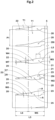
- FIG. 1 is a development of a tread portion 2 of a tire 1 according to an embodiment of the present disclosure.
- the tire 1 of the present embodiment is preferably used as, for example, a pneumatic tire for a passenger car.
- the present disclosure is not limited thereto, and may be applied to a heavy-duty pneumatic tire or a non-pneumatic tire the inside of which is not filled with pressurized air.
- the tread portion 2 includes a plurality of circumferential grooves 3 disposed between a first tread end T1 and a second tread end T2 so as to continuously extend in a tire circumferential direction, and a plurality of land portions 4 demarcated by the plurality of circumferential grooves 3.
- the tire 1 of the present embodiment is configured as a so-called five-rib tire in which the tread portion 2 includes five land portions 4 demarcated by four circumferential grooves 3.
- the present disclosure is not limited thereto.
- the tread portion 2 of the present embodiment has a designated mounting direction to a vehicle.
- the first tread end T1 is disposed on the outer side of a vehicle when the tire is mounted to the vehicle.
- the second tread end T2 is disposed on the inner side of the vehicle when the tire is mounted to the vehicle.
- the mounting direction to a vehicle is, for example, indicated by a character or symbol on a sidewall portion (not shown).
- the tire 1 according to the present disclosure is not limited thereto, and a mounting direction to a vehicle may not necessarily be designated.
- the first tread end T1 and the second tread end T2 each correspond to an outermost ground contact portion in the tire axial direction when 70% of a normal load is applied to the tire 1 in a normal state, and the tire 1 is in contact with a plane at a camber angle of 0°.
- the "normal state” represents a state in which the tire is mounted on a normal rim and is inflated to a normal internal pressure and no load is applied to the tire for pneumatic tires for which various standards are defined.
- the normal state represents a standard use state, corresponding to a purpose of use of the tire, in which the tire is not mounted to a vehicle and no load is applied to the tire.
- dimensions and the like of components of the tire are represented by values measured in the normal state.
- the "normal rim” represents a rim that is defined by a standard, in a standard system including the standard on which the tire is based, for each tire, and is, for example, “standard rim” in the JATMA standard, "Design Rim” in the TRA standard, or “Measuring Rim” in the ETRTO standard.
- the "normal internal pressure” represents an air pressure that is defined by a standard, in a standard system including the standard on which the tire is based, for each tire, and is “maximum air pressure” in the JATMA standard, the maximum value recited in the table "TIRE LOAD LIMITS AT VARIOUS COLD INFLATION PRESSURES" in the TRA standard, or "INFLATION PRESSURE” in the ETRTO standard.
- the "normal load” represents a load that is defined by a standard, in a standard system including the standard on which the tire is based, for each tire, and is "maximum load capacity" in the JATMA standard, the maximum value recited in the table "TIRE LOAD LIMITS AT VARIOUS COLD INFLATION PRESSURES" in the TRA standard, or "LOAD CAPACITY” in the ETRTO standard, for pneumatic tires for which various standards are defined.
- the "normal load” represents a load that acts on one tire in a standard mounting state of the tire.
- the "standard mounting state” represents a state in which a tire is mounted to a standard vehicle corresponding to the purpose of use of the tire and the vehicle is stationary on a flat road surface in a state where the vehicle can run.
- the plurality of circumferential grooves 3 include a first shoulder circumferential groove 5 disposed closest to the first tread end T1. Furthermore, the plurality of circumferential grooves 3 of the present embodiment include a second shoulder circumferential groove 6, a first crown circumferential groove 7, and a second crown circumferential groove 8. The second shoulder circumferential groove 6 is disposed closest to the second tread end T2. The first crown circumferential groove 7 is disposed between the first shoulder circumferential groove 5 and a tire equator C. The second crown circumferential groove 8 is disposed between the second shoulder circumferential groove 6 and the tire equator C.
- a distance L1 in the tire axial direction from the tire equator C to a groove center line of the first shoulder circumferential groove 5 or the second shoulder circumferential groove 6 is, for example, preferably 25% to 35% of a tread width TW.
- a distance L2 in the tire axial direction from the tire equator C to a groove center line of the first crown circumferential groove 7 or the second crown circumferential groove 8 is, for example, preferably 5% to 15% of the tread width TW.
- the tread width TW refers to a distance in the tire axial direction from the first tread end T1 to the second tread end T2 in the normal state.
- each circumferential groove 3 of the present embodiment linearly extends in parallel to the tire circumferential direction.
- Each circumferential groove 3 may extend, for example, in a wavy manner.
- Each circumferential groove 3 preferably has a groove width W1 of at least 3 mm.
- the groove width W1 of each circumferential groove 3 is, for example, preferably 4.0% to 8.5% of the tread width TW.
- the groove width refers to a distance between two edges of the groove in the normal state. The two edges refer to boundaries, between the opening of the groove and the ground-contact surface, formed when 70% of the normal load is applied to the tire 1 in the normal state, and the outer surface of the tread portion 2 is in contact with a plane at a camber angle of 0°.
- the first shoulder circumferential groove 5 has the smallest groove width among the plurality of circumferential grooves 3.
- Each circumferential groove 3 preferably has a depth of, for example, 5 to 10 mm in the case of a pneumatic tire for a passenger car.
- the plurality of land portions 4 include a first shoulder land portion 11.
- the first shoulder land portion 11 includes the first tread end T1, and is demarcated so as to be disposed outward of the first shoulder circumferential groove 5 in the tire axial direction.
- the land portions 4 include a second shoulder land portion 12, a first middle land portion 13, a second middle land portion 14, and a crown land portion 15.
- the second shoulder land portion 12 includes the second tread end T2, and is demarcated so as to be disposed outward of the second shoulder circumferential groove 6 in the tire axial direction.
- the first middle land portion 13 is demarcated between the first shoulder circumferential groove 5 and the first crown circumferential groove 7.
- the second middle land portion 14 is demarcated between the second shoulder circumferential groove 6 and the second crown circumferential groove 8.
- the crown land portion 15 is demarcated between the first crown circumferential groove 7 and the second crown circumferential groove 8.
- FIG. 2 is an enlarged view of the first shoulder land portion 11. As shown in FIG. 2 , a plurality of first shoulder lateral grooves 20 are disposed in the first shoulder land portion 11. The first shoulder lateral groove 20 extends from the first shoulder circumferential groove 5 to a position beyond the first tread end T1.
- At least one of the first shoulder lateral grooves 20 includes an inner end 20i connected to the first shoulder circumferential groove 5, a maximum groove width portion 21 at which the first shoulder lateral groove 20 has a maximum groove width W2 in the ground-contact surface of the first shoulder land portion 11, and an outer portion 22 disposed outward of the first tread end T1 in the tire axial direction.
- the maximum groove width portion 21 includes, in addition to a portion at which the first shoulder lateral groove 20 has the maximum groove width W2, a portion at which the first shoulder lateral groove 20 has a groove width of not less than 95% of the maximum groove width W2.
- a groove width W3 at the inner end 20i of the first shoulder lateral groove 20, and a groove width W4, on the first tread end T1, of the first shoulder lateral groove 20, are each less than the maximum groove width W2.
- the groove width of the outer portion 22 of the first shoulder lateral groove 20 is reduced outward in the tire axial direction.
- the maximum groove width portion 21, of the first shoulder lateral groove 20, disposed in the ground-contact surface of the first shoulder land portion 11 can exhibit excellent drainage performance, to significantly enhance wet performance.
- the groove width W3 at the inner end 20i of the first shoulder lateral groove 20, and the groove width W4 on the first tread end T1 are less than the maximum groove width W2. Therefore, even when a ground contact pressure acts on the first shoulder land portion 11, the first shoulder lateral groove 20 is unlikely to be opened, and the pattern stiffness of the first shoulder land portion 11 is maintained. Therefore, steering stability on dry road surfaces can be effectively maintained.
- the groove width of the outer portion 22 of the first shoulder lateral groove 20 is reduced outward in the tire axial direction. Therefore, a region of the first shoulder land portion 11 disposed outward of the first tread end T1 has a high stiffness.
- the tire comes into contact with the ground in a region having a high stiffness, and the steering stability is more assuredly maintained. It is inferred that the above-described mechanism allows the tire according to the present disclosure to have enhanced wet performance while maintaining steering stability on dry road surfaces.
- the structure of the present embodiment will be described below in more detail.
- the structures described below represent specific modes of the present embodiment. Therefore, needless to say, also when the structures described below are not provided, the technique of the present disclosure can exhibit the above-described effects. Also when any one of the structures described below is applied alone to the tire of the present disclosure having the above-described features, improvement of performance corresponding to each structure can be expected. Furthermore, in a case where some of the structures described below are applied in combination, complex performance improvement corresponding to the structures can be expected.
- the plurality of first shoulder lateral grooves 20 are merely disposed, and no other grooves or recesses are disposed.
- the plurality of first shoulder lateral grooves 20 have substantially the same shape.
- One pitch length P1 in the tire circumferential direction between two first shoulder lateral grooves 20 adjacent to each other in the tire circumferential direction is, for example, 100% to 120% of a width W5, in the tire axial direction, of the ground-contact surface of the first shoulder land portion 11.
- the one pitch length represents a distance in the tire circumferential direction between the groove center lines of two first shoulder lateral grooves 20 adjacent to each other in the tire circumferential direction. In a case where the distance in the tire circumferential direction varies in the tire axial direction, the center value is adopted.
- the groove width W3 of the inner end 20i of the first shoulder lateral groove 20 is, for example, 50% to 90% and preferably 70% to 80% of the maximum groove width W2.
- the first shoulder lateral groove 20 which includes the inner end 20i having such a structure contributes to well-balanced enhancement of steering stability and wet performance.
- FIG. 3 is an enlarged view of the first shoulder lateral groove 20.
- the first shoulder lateral groove 20 of the present embodiment includes, for example, an inner portion 23 that extends outward from the inner end 20i in the tire axial direction with a uniform groove width.
- a length L4, in the tire axial direction, of the inner portion 23 is, for example, 10% to 30% and preferably 15% to 25% of the width W5 (shown in FIG. 2 , the same applies to the following description) of the ground-contact surface of the first shoulder land portion 11.
- the inner portion 23 having such a structure contributes to well-balanced enhancement of steering stability and wet performance.
- the structure such as the length of the groove is measured and defined at the groove center line.
- the first shoulder lateral groove 20 includes, for example, a body portion 25 between the inner portion 23 and the outer portion 22.
- the body portion 25 includes the maximum groove width portion 21 described above.
- the maximum groove width portion 21 is connected so as to be disposed outward of the inner portion 23 in the tire axial direction. Specifically, an edge 23a on one side (upper side in FIG. 3 ), in the tire circumferential direction, of the inner portion 23, and an edge 21a on the one side, in the tire circumferential direction, of the maximum groove width portion 21 are linearly connected directly to each other. An edge 23b on the other side (lower side in FIG.
- the groove width of the first shoulder lateral groove 20 increases stepwise in the inner portion 23 and the maximum groove width portion 21.
- the maximum groove width portion 21 of the present embodiment is disposed at almost the center, in the tire axial direction, of the ground-contact surface of the first shoulder land portion 11.
- This configuration includes at least an embodiment in which the maximum groove width portion 21 extends across the center position, in the tire axial direction, of the ground-contact surface of the first shoulder land portion 11.
- the configuration also includes an embodiment in which, even when the maximum groove width portion 21 does not extend across the center position, a distance between the maximum groove width portion 21 and the center position is not greater than 5% of the width W5, in the tire axial direction, of the ground-contact surface of the first shoulder land portion 11.
- the maximum groove width W2 is, for example, 20% to 35% of the one pitch length P1 for the first shoulder lateral groove 20.
- a length L5, in the tire axial direction, of the maximum groove width portion 21 is, for example, 25% to 45% and preferably 30% to 40% of the width W5, in the tire axial direction, of the ground-contact surface of the first shoulder land portion 11.
- the first shoulder lateral groove 20 that includes the maximum groove width portion 21 having such a structure can exhibit excellent wet performance while maintaining steering stability.
- the body portion 25 includes, for example, a groove width reduction portion 26 having a groove width reduced from the maximum groove width portion 21 toward the first tread end T1.
- An edge on the one side, in the tire circumferential direction, of the groove width reduction portion 26 includes a portion 26a1 that is connected to the edge 21a of the maximum groove width portion 21 and extends at an angle greater than that of the edge of the maximum groove width portion 21 with respect to the tire axial direction, and a portion 26a2 that extends to the first tread end T1 at the same angle as that of the edge of the maximum groove width portion 21 with respect to the tire axial direction.
- An edge on the other side, in the tire circumferential direction, of the groove width reduction portion 26 includes a portion 26b1 that is linearly connected directly to the edge of the maximum groove width portion 21, and a portion 26b2 that extends to the first tread end T1 at an angle greater than that of the edge 21b of the maximum groove width portion 21 with respect to the tire axial direction.
- turbulent flow is unlikely to occur when water moves in the groove, and the groove width in the vicinity of the first tread end T1 can be reduced while the drainage of the first shoulder lateral groove 20 is maintained.
- the groove width W4, at the first tread end T1, of the first shoulder lateral groove 20 is, for example, 45% to 70% and preferably 50% to 65% of the maximum groove width W2.
- the first shoulder lateral groove 20 having such a structure can also reduce pitch sound that occurs during running on a dry road surface while exhibiting the above-described effects.
- the groove width of the outer portion 22 of the present embodiment is continuously reduced outward from the first tread end T1 in the tire axial direction.
- uneven wear around the outer portion 22 is reduced.
- the present disclosure is not limited thereto, and the outer portion 22 may include, for example, a portion extending with a uniform groove width.
- the outer portion 22 includes, for example, a first portion 27 on the first tread end T1 side, and a second portion 28 disposed outward of the first portion 27 in the tire axial direction.
- the groove width of the first portion 27 is reduced outward in the tire axial direction at a first reduction rate.
- the groove width of the second portion 28 is reduced outward in the tire axial direction at a second reduction rate less than the first reduction rate.
- the outer portion 22 having such a structure can provide excellent steering stability even in a high load applied state in which a high load acts on the tread portion.
- the high load applied state means that, as in the front wheel during braking or the outer wheel during cornering, a higher load acts on the tread portion than during normal running, and the outer portion 22 (particularly, the second portion 28) is in contact with the ground.
- the first and second reduction rates are each defined as a ratio of the maximum groove width of the corresponding portion relative to the smallest groove width of the portion.
- the first reduction rate of the first portion 27 is, for example, 200% to 300%.
- the second reduction rate of the second portion 28 is, for example, 130% to 200%.
- the angle between the two edges of the first portion 27 is, for example, 10 to 25°.
- the angle between the two edges of the second portion 28 is less than that of the first portion 27, and is, for example, less than 10°.
- a length L6, in the tire axial direction, of the outer portion 22 is, for example, not greater than the width W5, in the tire axial direction, of the ground-contact surface of the first shoulder land portion 11. Specifically, the length L6 is 70% to 90% and preferably 75% to 85% of the width W5. As shown in FIG. 3 , a length L7, in the tire axial direction, of the first portion 27 is 20% to 50% of the length L6, in the tire axial direction, of the outer portion 22. A length L8, in the tire axial direction, of the second portion 28 is 50% to 80% of the length L6 (shown in FIG. 2 , the same applies to the following description), in the tire axial direction, of the outer portion 22.
- the outer portion 22 having such a structure allows well-balanced enhancement of wet performance and steering stability in the high load applied state.
- the length L8 of the second portion 28 is, for example, preferably greater than the length L4, in the tire axial direction, of the inner portion 23.
- the length L8 of the second portion 28 is, for example, preferably less than a length L9, in the tire axial direction, of a portion of the first shoulder lateral groove 20 excluding the second portion 28 and the inner portion 23.
- a groove width W6 at a boundary between the first portion 27 and the second portion 28 is, for example, 25% to 35% of the maximum groove width W2.
- a groove width W7 at an outer end, in the tire axial direction, of the first shoulder lateral groove 20 is, for example, 10% to 30% and preferably 15% to 25% of the maximum groove width W2.
- the groove width at the outer end represents a groove width at ends, in the tire axial direction, of two edges extending along a groove length direction.
- the first shoulder lateral groove 20 has, for example, the maximum depth at the body portion 25.
- the maximum depth of the first shoulder lateral groove 20 is, for example, 60% to 90% and preferably 70% to 80% of the maximum depth of the first shoulder circumferential groove 5.
- the inner portion 23 has a depth less than that of the body portion 25.
- the maximum depth of the inner portion 23 is, for example, 45% to 65% and preferably 50% to 60% of the maximum depth of the first shoulder lateral groove 20.
- the depth of the outer portion 22 is reduced outward in the tire axial direction.
- the depth at the outer end of the first shoulder lateral groove 20 is, for example, 5% to 25% and preferably 10% to 20% of the maximum depth of the first shoulder lateral groove 20.
- the outer portion 22 having such a structure contributes to well-balanced enhancement of steering stability and wet performance.
- FIG. 4 is a cross-sectional view taken along a line A-A of the first shoulder lateral groove 20 in FIG. 2 .
- a chamfered portion 30 is, for example, preferably connected to at least a portion of the edge of the first shoulder lateral groove 20.
- the chamfered portion 30 includes an inclined surface 30a extending diagonally from the edge.
- the inclined surface 30a extends so as to be inclined between the ground-contact surface of the first shoulder land portion 11 and a groove wall of the first shoulder lateral groove 20.
- the angle of the inclined surface 30a with respect to the tire radial direction is, for example, 30 to 60°.
- the inclined surface 30a has a width of not greater than 2 mm and of preferably 0.5 to 1.5 mm, in the tread planar view.
- the inclined surface 30a has a depth of not greater than 2 mm and of preferably 0.5 to 1.5 mm.
- the chamfered portion 30 having such a structure contributes to reduction of uneven wear of the first shoulder land portion 11.
- the groove width of the groove in the description herein represents a distance between the two edges of the groove in the normal state.
- the two edges refer to boundaries, between the opening of the groove and the ground-contact surface, formed when 70% of the normal load is applied to the tire 1 in the normal state, and the outer surface of the tread portion 2 is in contact with a plane at a camber angle of 0°.
- dots are formed on the inclined surface 30a of the chamfered portion 30.
- an edge (edge on the upper side in FIG. 3 ) on the one side, in the tire circumferential direction, of the first shoulder lateral groove 20 and an edge (edge on the lower side in FIG. 3 ) on the other side, in the tire circumferential direction, of the first shoulder lateral groove 20 each have both a region to which the chamfered portion 30 is connected and a region to which the chamfered portion 30 is not connected (hereinafter, such a region is referred to as a non-chamfered portion 31).
- the non-chamfered portion 31 refers to a portion in which the ground-contact surface of the first shoulder land portion 11 is connected to the groove wall of the first shoulder lateral groove 20 to form an angular portion having an almost right angle.
- the chamfered portion 30 connected to the edge on the one side preferably extends from the inner end 20i of the first shoulder lateral groove 20 to a position preceding the first tread end T1. That is, on the first tread end T1, the edge on the one side is formed as the non-chamfered portion 31.
- a distance between an end of the chamfered portion 30 and the first tread end T1 is, for example, 3 to 15 mm and preferably 5 to 10 mm.
- the edge on the one side linearly extends from the inner end 20i to the maximum groove width portion 21 in the first shoulder lateral groove 20.
- the chamfered portion 30 connected to the edge on the one side extends from the inner end 20i to the maximum groove width portion 21 in the first shoulder lateral groove 20 with a uniform width. Thus, uneven wear of the first shoulder land portion 11 is reduced.
- the chamfered portion 30 connected to the edge on the other side is disposed at least in the inner portion 23 and the maximum groove width portion 21 of the first shoulder lateral groove 20.
- the chamfered portion 30 connected to the edge on the other side extends from the maximum groove width portion 21 to a position beyond the first tread end T1. That is, on the first tread end T1, the chamfered portion 30 is connected to the edge on the other side.
- a distance from an end, in the tire axial direction, of the chamfered portion 30 connected to the edge on the other side to the first tread end T1 is, for example, not greater than 5 mm.
- the edge on the one side of the first shoulder lateral groove 20 is formed as the non-chamfered portion 31, and the chamfered portion 30 is connected to the edge on the other side of the first shoulder lateral groove 20.
- Such an arrangement of the chamfered portion 30 can reduce uneven wear in the vicinity of the first tread end T1 in the first shoulder lateral groove 20 while ensuring frictional force due to the edge in the vicinity of the first tread end T1.
- the inner portion 23 and the maximum groove width portion 21 of the first shoulder lateral groove 20 are structured such that the chamfered portions 30 are connected to the edges on both sides except for the circumferential edge 24.
- An edge 22a on the one side, in the tire circumferential direction, of the outer portion 22 is entirely formed as the non-chamfered portion 31.
- the chamfered portion 30 is connected merely to an end portion, on the first tread end T1 side, of an edge 22b on the other side, in the tire circumferential direction, of the outer portion 22, and the other portion of the edge 22b is formed as the non-chamfered portion 31. Therefore, at least in the second portion 28, the edges on both sides are each formed as the non-chamfered portion 31.
- uneven wear of the first shoulder land portion 11 can be reduced, and, when the outer portion 22 is in contact with the ground, the non-chamfered portion 31 can provide a high frictional force.
- the chamfered portion 30 is connected to an edge 25a on the one side, in the tire circumferential direction, of the body portion 25 in a portion connected to the maximum groove width portion 21, and an end portion of the edge 25a on the first tread end T1 side is formed as the non-chamfered portion 31.
- the chamfered portion 30 is connected to the entirety of an edge 25b on the other side, in the tire circumferential direction, of the body portion 25.
- FIG. 5 is an enlarged view of the second shoulder land portion 12. As shown in FIG. 5 , a plurality of second shoulder lateral grooves 35 are disposed in the second shoulder land portion 12.
- the second shoulder lateral groove 35 of the present embodiment includes, for example, a body portion 36 extending from a position away from the second shoulder circumferential groove 6 to the second tread end T2, and an outer portion 37 disposed outward of the second tread end T2 in the tire axial direction.
- the above-described configuration of the outer portion 22 (shown in FIGS. 2 and 3 ) of the first shoulder lateral groove 20 can be applied to the outer portion 37 of the second shoulder lateral groove 35.
- the configuration of the body portion 25 of the first shoulder lateral groove 20, excluding a configuration described below, can be applied to the body portion 36 of the second shoulder lateral groove 35.
- a distance L10 in the tire axial direction from the body portion 36 of the second shoulder lateral groove 35 to the second shoulder circumferential groove 6 is, for example, 5% to 15% of a width W8, in the tire axial direction, of the ground-contact surface of the second shoulder land portion 12.
- the second shoulder lateral groove 35 that includes the body portion 36 having such a structure can enhance wet performance while maintaining stiffness of the second shoulder land portion 12.
- the body portion 36 of the second shoulder lateral groove 35 includes, at an inner end thereof in the tire axial direction, an inclined edge 35a that extends in the tire circumferential direction so as to be inclined.
- An angle of the inclined edge 35a with respect to the tire circumferential direction is, for example, 20 to 40°.
- the inclined edge 35a having such a structure provides a frictional force in the tire axial direction, and enhances cornering performance on wet road surfaces.
- the second shoulder lateral groove 35 of the present embodiment includes a standard second shoulder lateral groove 35A and a shallow-groove-equipped second shoulder lateral groove 35B.
- the standard second shoulder lateral grooves 35A and the shallow-groove-equipped second shoulder lateral grooves 35B alternate in the tire circumferential direction.
- the standard second shoulder lateral groove 35A does not have a groove between the body portion 36 and the second shoulder circumferential groove 6.
- the shallow-groove-equipped second shoulder lateral groove 35B includes a shallow groove portion 38 that extends from the body portion 36 to the second shoulder circumferential groove 6.
- the shallow groove portion 38 has a groove width and depth of, for example, 0.3 to 1.5 mm and preferably 0.5 to 1.0 mm.
- the shallow groove portion 38 having such a structure can supplement a frictional force in the tire axial direction on wet road surfaces.
- FIG. 6 is an enlarged view of the first middle land portion 13, the second middle land portion 14, and the crown land portion 15. As shown in FIG. 6 , in the first middle land portion 13, a plurality of first middle lateral grooves 41 and a plurality of first middle terminating grooves 42 are disposed. The first middle lateral grooves 41 and the first middle terminating grooves 42 preferably alternate in the tire circumferential direction.
- the first middle lateral groove 41 includes, for example, a body portion 43 that extends from the first shoulder circumferential groove 5 in the tire axial direction, and a shallow groove portion 44 that extends from the body portion 43 to the first crown circumferential groove 7.
- the body portion 43 is, for example, preferably connected to the first shoulder circumferential groove 5 at a position different from the inner portion 23 of the first shoulder lateral groove 20 in the tire circumferential direction.
- the body portion 43 of the first middle lateral groove 41 is, for example, disposed at an angle of not greater than 10° with respect to the tire axial direction.
- a length L11, in the tire axial direction, of the body portion 43 is, for example, 40% to 60% of a width W9, in the tire axial direction, of the ground-contact surface of the first middle land portion 13.
- the length L11, in the tire axial direction, of the body portion 43 of the first middle lateral groove 41 is greater than a length, in the tire axial direction, of the inner portion 23 (shown in FIG. 2 ) of the first shoulder lateral groove 20, and is less than the length, in the tire axial direction, of the body portion 25 (shown in FIG. 2 ) of the first shoulder lateral groove 20.
- the first middle lateral groove 41 that includes the body portion 43 having such a structure contributes to well-balanced enhancement of steering stability and wet performance.
- the maximum groove width of the body portion 43 is, for example, preferably less than the maximum groove width W2 (shown in FIG. 2 ) of the first shoulder lateral groove 20, and preferably less than the groove width W3 (shown in FIG. 2 ) at the inner end 20i of the first shoulder lateral groove 20.
- the maximum groove width of the body portion 43 is 35% to 50% of the maximum groove width W2 of the first shoulder lateral groove 20.
- the first middle lateral groove 41 that includes the body portion 43 having such a structure can enhance steering stability and wet performance in cooperation with the first shoulder lateral groove 20.
- the body portion 43 includes, for example, a wide width portion 43a that is connected to the first shoulder circumferential groove 5, and a narrow width portion 43b that has a groove width less than that of the wide width portion 43a.
- a groove width of the narrow width portion 43b is 60% to 90% of the groove width of the wide width portion 43a.
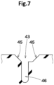
- FIG. 7 is a cross-sectional view taken along a line B-B in FIG. 6 .
- a chamfered portion 45 is preferably connected to an edge of the body portion 43 of the first middle lateral groove 41.
- a narrow groove portion 46 having a width of 0.5 to 1.5 mm is connected and disposed inward of the chamfered portions 45 in the tire radial direction.
- a depth of the body portion 43 including the depths of the chamfered portion 45 and the narrow groove portion 46 is, for example, 40% to 60% of the maximum depth of the first shoulder circumferential groove 5.
- the first middle lateral groove 41 that includes the body portion 43 having such a structure can maintain stiffness of the first middle land portion 13 and enhance steering stability.
- a groove width and depth of the shallow groove portion 44 of the first middle lateral groove 41 are, for example, 0.3 to 1.5 mm and preferably 0.5 to 1.0 mm.
- the shallow groove portion 44 is, for example, disposed at an angle greater than that of the body portion 43 with respect to the tire axial direction.
- the angle of the shallow groove portion 44 with respect to the tire axial direction is, for example, 50 to 70°.
- the shallow groove portion 44 having such a structure can provide, with its edge, a frictional force in the tire axial direction, and can enhance cornering performance on wet road surfaces.
- the first middle terminating groove 42 extends from the first shoulder circumferential groove 5 and terminates in the first middle land portion 13.
- a length L12, in the tire axial direction, of the first middle terminating groove 42 is, for example, less than the length, in the tire axial direction, of the body portion 43 of the first middle lateral groove 41.
- the length L12 of the first middle terminating groove 42 is 20% to 30% of the width W9, in the tire axial direction, of the ground-contact surface of the first middle land portion 13.
- the first middle terminating groove 42 having such a structure can enhance wet performance while maintaining stiffness of the first middle land portion 13.
- the first middle terminating groove 42 has substantially the same transverse cross-section as the transverse cross-section, shown in FIG. 7 , of the body portion 43 of the first middle lateral groove 41. Therefore, the configuration of the transverse cross-section of the first middle lateral groove 41 can be applied to the transverse cross-section of the first middle terminating groove 42.
- the second middle lateral groove 50 includes a body portion 51 that extends from the second shoulder circumferential groove 6, and a shallow groove portion 52 that extends from the body portion 51 to the second crown circumferential groove 8.
- the above-described configurations of the body portion 43 and the shallow groove portion 44 of the first middle lateral groove 41, excluding configurations described below, can be applied to the body portion 51 and the shallow groove portion 52 of the second middle lateral groove 50.
- the body portion 51 of the second middle lateral groove 50 terminates without extending across the center position, in the tire axial direction, of the ground-contact surface of the second middle land portion 14.
- a length L13, in the tire axial direction, of the body portion 51 of the second middle lateral groove 50 is 30% to 50% of a width W10, in the tire axial direction, of the ground-contact surface of the second middle land portion 14.
- the length L13, in the tire axial direction, of the body portion 51 of the second middle lateral groove 50 is less than the length L11, in the tire axial direction, of the body portion 43 of the first middle lateral groove 41.
- a plurality of first crown lateral grooves 56 and a plurality of second crown lateral grooves 57 are disposed.
- the first crown lateral groove 56 extends from the first crown circumferential groove 7 and terminates in the crown land portion 15 without reaching the second crown circumferential groove 8.
- a length L14, in the tire axial direction, of the first crown lateral groove 56 is, for example, 10% to 30% of a width W11, in the tire axial direction, of the ground-contact surface of the crown land portion 15.
- the length L14 of the first crown lateral groove 56 is less than each of the length L11, in the tire axial direction, of the body portion 43 of the first middle lateral groove 41, the length L12, in the tire axial direction, of the first middle terminating groove 42, and the length L13, in the tire axial direction, of, the body portion 51 of the second middle lateral groove 50.
- the first crown lateral groove 56 having such a structure can assuredly maintain stiffness of the crown land portion 15 and can enhance steering stability while supplementing wet performance.
- the second crown lateral groove 57 includes, for example, a body portion 58 that extends from the second crown circumferential groove 8 in the tire axial direction, and a shallow groove portion 59 that extends from the body portion 58 and terminates without reaching the first crown circumferential groove 7.
- the body portion 58 of the second crown lateral groove 57 extends from the second crown circumferential groove 8 and terminates in the crown land portion 15 without reaching the first crown circumferential groove 7.
- a length L15, in the tire axial direction, of the body portion 58 of the second crown lateral groove 57 is, for example, 45% to 60% of the width W11, in the tire axial direction, of the ground-contact surface of the crown land portion 15.
- the length L15 of the body portion 58 of the second crown lateral groove 57 is preferably less than the length L11, in the tire axial direction, of the body portion 43 of the first middle lateral groove 41, and greater than the length L13, in the tire axial direction, of the body portion 51 of the second middle lateral groove 50.
- the second crown lateral groove 57 that includes the body portion 58 having such a structure contributes to well-balanced enhancement of steering stability and wet performance.
- the shallow groove portion 59 of the second crown lateral groove 57 has a groove width and depth of, for example, 0.3 to 1.5 mm and preferably 0.5 to 1.0 mm.
- the shallow groove portion 59 of the second crown lateral groove 57 extends at an angle greater than that of the body portion 58 with respect to the tire axial direction.
- the shallow groove portion 59 of the second crown lateral groove 57 is inclined in the same direction as the direction in which the shallow groove portion 44 of the first middle lateral groove 41 is inclined.
- the angle of the shallow groove portion 59 of the second crown lateral groove 57 with respect to the tire axial direction is, for example, 50 to 70°.
- the second crown lateral groove 57 that includes the shallow groove portion 59 having such a structure contributes to enhancement of cornering performance during running on wet road surfaces.
- Tires having a size of 225/50R17 and the basic pattern shown in FIG. 1 were produced as test tires according to the specifications indicated in Tables 1 to 3.
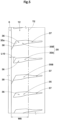
- a tire having a tread portion shown in FIG. 8 was produced as a test tire.
- Each shoulder lateral groove a of the tire of the comparative example extended in the tire axial direction with a uniform groove width.
- the tire of the comparative example was substantially the same as the tire shown in FIG. 1 , except for the above-described structure.
- steering stability and wet performance were tested. Specifications common to the test tires and test methods were as follows.
- FIG. 1 FIG. 1 FIG. 1 FIG. 1 Groove width W3 at inner end/maximum groove width W2 (%) in first shoulder lateral groove 75 75 75 75 Groove width W4 at first tread end/maximum groove width W2 (%) in first shoulder lateral groove 58 58 58 58 Groove width W7 at outer end/maximum groove width W2 (%) in first shoulder lateral groove 20 20 20 20 Length L4 of inner portion/width W5 of first shoulder land portion (%) 20 20 20 20 20 20 Length L6 of outer portion/width W5 of first shoulder land portion (%) 70 75 85 90 Steering stability (score) 108 107 107 106 Wet performance (score) 104 105 105 106
- the present disclosure includes the following aspects.
- a tire including a tread portion, in which
- the groove width of the inner end is 50% to 70% of the maximum groove width.
- a length, in the tire axial direction, of the second portion is less than a length, in the tire axial direction, of a portion of the first shoulder lateral groove excluding the second portion and the inner portion.
- the chamfered portion connected to the edge on the one side extends from the inner end of the first shoulder lateral groove to a position preceding the first tread end.
- the chamfered portion connected to the edge on the other side extends from the maximum groove width portion to a position beyond the first tread end.
Landscapes
- Engineering & Computer Science (AREA)
- Mechanical Engineering (AREA)
- Tires In General (AREA)
Abstract
Description
- The present disclosure relates to a tire.
-
Japanese Laid-Open Patent Publication No. 2013-139166 - In recent years, tires have been required to have further enhanced wet performance. Meanwhile, the enhancement of wet performance should not impair steering stability on dry road surfaces.
- The present disclosure has been made in view of the aforementioned circumstances, and a main object of the present disclosure is to provide a tire having enhanced wet performance while maintaining steering stability on dry road surfaces.
- The present disclosure is directed to a tire including a tread portion. The tread portion includes a plurality of circumferential grooves disposed between a first tread end and a second tread end so as to continuously extend in a tire circumferential direction, and a plurality of land portions demarcated by the plurality of circumferential grooves. The plurality of circumferential grooves include a first shoulder circumferential groove disposed closest to the first tread end. The plurality of land portions include a first shoulder land portion demarcated by the first shoulder circumferential groove, the first shoulder land portion including the first tread end. The first shoulder land portion includes a plurality of first shoulder lateral grooves extending from the first shoulder circumferential groove to a position beyond the first tread end. At least one of the first shoulder lateral grooves includes an inner end connected to the first shoulder circumferential groove, a maximum groove width portion at which the first shoulder lateral groove has a maximum groove width in a ground-contact surface of the first shoulder land portion, and an outer portion disposed outward of the first tread end in a tire axial direction. A groove width at the inner end and a groove width, on the first tread end, of the first shoulder lateral groove are each less than the maximum groove width. A groove width of the outer portion is reduced outward in the tire axial direction.
- The tire of the present disclosure has the above-described configuration and can thus have enhanced wet performance while maintaining steering stability on dry road surfaces.
-
-
FIG. 1 is a development of a tread portion according to an embodiment of the present disclosure; -
FIG. 2 is an enlarged view of a first shoulder land portion inFIG. 1 ; -
FIG. 3 is an enlarged view of a first shoulder lateral groove inFIG. 2 ; -
FIG. 4 is a cross-sectional view taken along a line A-A inFIG. 2 ; -
FIG. 5 is an enlarged view of a second shoulder land portion inFIG. 1 ; -
FIG. 6 is an enlarged view of a first middle land portion, a second middle land portion, and a crown land portion inFIG. 1 ; -
FIG. 7 is a cross-sectional view taken along a line B-B inFIG. 6 ; and -
FIG. 8 is a development of a tread portion of a tire of a comparative example. - An embodiment of the present disclosure will be described below with reference to the drawings.
FIG. 1 is a development of atread portion 2 of a tire 1 according to an embodiment of the present disclosure. The tire 1 of the present embodiment is preferably used as, for example, a pneumatic tire for a passenger car. However, the present disclosure is not limited thereto, and may be applied to a heavy-duty pneumatic tire or a non-pneumatic tire the inside of which is not filled with pressurized air. - As shown in
FIG. 1 , thetread portion 2 according to the present disclosure includes a plurality ofcircumferential grooves 3 disposed between a first tread end T1 and a second tread end T2 so as to continuously extend in a tire circumferential direction, and a plurality ofland portions 4 demarcated by the plurality ofcircumferential grooves 3. The tire 1 of the present embodiment is configured as a so-called five-rib tire in which thetread portion 2 includes fiveland portions 4 demarcated by fourcircumferential grooves 3. However, the present disclosure is not limited thereto. - For example, the
tread portion 2 of the present embodiment has a designated mounting direction to a vehicle. Thus, the first tread end T1 is disposed on the outer side of a vehicle when the tire is mounted to the vehicle. The second tread end T2 is disposed on the inner side of the vehicle when the tire is mounted to the vehicle. The mounting direction to a vehicle is, for example, indicated by a character or symbol on a sidewall portion (not shown). The tire 1 according to the present disclosure is not limited thereto, and a mounting direction to a vehicle may not necessarily be designated. - The first tread end T1 and the second tread end T2 each correspond to an outermost ground contact portion in the tire axial direction when 70% of a normal load is applied to the tire 1 in a normal state, and the tire 1 is in contact with a plane at a camber angle of 0°.
- The "normal state" represents a state in which the tire is mounted on a normal rim and is inflated to a normal internal pressure and no load is applied to the tire for pneumatic tires for which various standards are defined. For non-pneumatic tires and tires for which various standards are not defined, the normal state represents a standard use state, corresponding to a purpose of use of the tire, in which the tire is not mounted to a vehicle and no load is applied to the tire. In the description herein, unless otherwise specified, dimensions and the like of components of the tire are represented by values measured in the normal state.
- The "normal rim" represents a rim that is defined by a standard, in a standard system including the standard on which the tire is based, for each tire, and is, for example, "standard rim" in the JATMA standard, "Design Rim" in the TRA standard, or "Measuring Rim" in the ETRTO standard.
- The "normal internal pressure" represents an air pressure that is defined by a standard, in a standard system including the standard on which the tire is based, for each tire, and is "maximum air pressure" in the JATMA standard, the maximum value recited in the table "TIRE LOAD LIMITS AT VARIOUS COLD INFLATION PRESSURES" in the TRA standard, or "INFLATION PRESSURE" in the ETRTO standard.
- The "normal load" represents a load that is defined by a standard, in a standard system including the standard on which the tire is based, for each tire, and is "maximum load capacity" in the JATMA standard, the maximum value recited in the table "TIRE LOAD LIMITS AT VARIOUS COLD INFLATION PRESSURES" in the TRA standard, or "LOAD CAPACITY" in the ETRTO standard, for pneumatic tires for which various standards are defined. For non-pneumatic tires and tires for which various standards are not defined, the "normal load" represents a load that acts on one tire in a standard mounting state of the tire. The "standard mounting state" represents a state in which a tire is mounted to a standard vehicle corresponding to the purpose of use of the tire and the vehicle is stationary on a flat road surface in a state where the vehicle can run.
- The plurality of
circumferential grooves 3 include a first shouldercircumferential groove 5 disposed closest to the first tread end T1. Furthermore, the plurality ofcircumferential grooves 3 of the present embodiment include a second shouldercircumferential groove 6, a first crowncircumferential groove 7, and a second crowncircumferential groove 8. The second shouldercircumferential groove 6 is disposed closest to the second tread end T2. The first crowncircumferential groove 7 is disposed between the first shouldercircumferential groove 5 and a tire equator C. The second crowncircumferential groove 8 is disposed between the second shouldercircumferential groove 6 and the tire equator C. - A distance L1 in the tire axial direction from the tire equator C to a groove center line of the first shoulder
circumferential groove 5 or the second shouldercircumferential groove 6 is, for example, preferably 25% to 35% of a tread width TW. A distance L2 in the tire axial direction from the tire equator C to a groove center line of the first crowncircumferential groove 7 or the second crowncircumferential groove 8 is, for example, preferably 5% to 15% of the tread width TW. The tread width TW refers to a distance in the tire axial direction from the first tread end T1 to the second tread end T2 in the normal state. - For example, each
circumferential groove 3 of the present embodiment linearly extends in parallel to the tire circumferential direction. Eachcircumferential groove 3 may extend, for example, in a wavy manner. - Each
circumferential groove 3 preferably has a groove width W1 of at least 3 mm. The groove width W1 of eachcircumferential groove 3 is, for example, preferably 4.0% to 8.5% of the tread width TW. In the description herein, the groove width refers to a distance between two edges of the groove in the normal state. The two edges refer to boundaries, between the opening of the groove and the ground-contact surface, formed when 70% of the normal load is applied to the tire 1 in the normal state, and the outer surface of thetread portion 2 is in contact with a plane at a camber angle of 0°. - In the present embodiment, the first shoulder
circumferential groove 5 has the smallest groove width among the plurality ofcircumferential grooves 3. However, the present disclosure is not limited thereto. Eachcircumferential groove 3 preferably has a depth of, for example, 5 to 10 mm in the case of a pneumatic tire for a passenger car. - The plurality of
land portions 4 according to the present disclosure include a firstshoulder land portion 11. The firstshoulder land portion 11 includes the first tread end T1, and is demarcated so as to be disposed outward of the first shouldercircumferential groove 5 in the tire axial direction. - The
land portions 4 according to the present disclosure include a secondshoulder land portion 12, a firstmiddle land portion 13, a secondmiddle land portion 14, and acrown land portion 15. The secondshoulder land portion 12 includes the second tread end T2, and is demarcated so as to be disposed outward of the second shouldercircumferential groove 6 in the tire axial direction. The firstmiddle land portion 13 is demarcated between the first shouldercircumferential groove 5 and the firstcrown circumferential groove 7. The secondmiddle land portion 14 is demarcated between the second shouldercircumferential groove 6 and the secondcrown circumferential groove 8. Thecrown land portion 15 is demarcated between the firstcrown circumferential groove 7 and the secondcrown circumferential groove 8. -
FIG. 2 is an enlarged view of the firstshoulder land portion 11. As shown inFIG. 2 , a plurality of firstshoulder lateral grooves 20 are disposed in the firstshoulder land portion 11. The firstshoulder lateral groove 20 extends from the first shouldercircumferential groove 5 to a position beyond the first tread end T1. - At least one of the first
shoulder lateral grooves 20 includes aninner end 20i connected to the first shouldercircumferential groove 5, a maximumgroove width portion 21 at which the firstshoulder lateral groove 20 has a maximum groove width W2 in the ground-contact surface of the firstshoulder land portion 11, and anouter portion 22 disposed outward of the first tread end T1 in the tire axial direction. The maximumgroove width portion 21 includes, in addition to a portion at which the firstshoulder lateral groove 20 has the maximum groove width W2, a portion at which the firstshoulder lateral groove 20 has a groove width of not less than 95% of the maximum groove width W2. - A groove width W3 at the
inner end 20i of the firstshoulder lateral groove 20, and a groove width W4, on the first tread end T1, of the firstshoulder lateral groove 20, are each less than the maximum groove width W2. In addition, the groove width of theouter portion 22 of the firstshoulder lateral groove 20 is reduced outward in the tire axial direction. In the present disclosure, by adopting the above-described configuration, wet performance can be enhanced while steering stability on dry road surfaces (hereinafter, may be simply referred to as "steering stability") is maintained. As the reason, the following mechanism is inferred. - In the present disclosure, the maximum
groove width portion 21, of the firstshoulder lateral groove 20, disposed in the ground-contact surface of the firstshoulder land portion 11 can exhibit excellent drainage performance, to significantly enhance wet performance. - In addition, in the present disclosure, the groove width W3 at the
inner end 20i of the firstshoulder lateral groove 20, and the groove width W4 on the first tread end T1, are less than the maximum groove width W2. Therefore, even when a ground contact pressure acts on the firstshoulder land portion 11, the firstshoulder lateral groove 20 is unlikely to be opened, and the pattern stiffness of the firstshoulder land portion 11 is maintained. Therefore, steering stability on dry road surfaces can be effectively maintained. - Furthermore, in the present disclosure, the groove width of the
outer portion 22 of the firstshoulder lateral groove 20 is reduced outward in the tire axial direction. Therefore, a region of the firstshoulder land portion 11 disposed outward of the first tread end T1 has a high stiffness. Thus, for example, on the outer side of the tire during cornering, when increase of a ground contact pressure moves the ground contact end outward in the tire axial direction, the tire comes into contact with the ground in a region having a high stiffness, and the steering stability is more assuredly maintained. It is inferred that the above-described mechanism allows the tire according to the present disclosure to have enhanced wet performance while maintaining steering stability on dry road surfaces. - The structure of the present embodiment will be described below in more detail. The structures described below represent specific modes of the present embodiment. Therefore, needless to say, also when the structures described below are not provided, the technique of the present disclosure can exhibit the above-described effects. Also when any one of the structures described below is applied alone to the tire of the present disclosure having the above-described features, improvement of performance corresponding to each structure can be expected. Furthermore, in a case where some of the structures described below are applied in combination, complex performance improvement corresponding to the structures can be expected.
- In the first
shoulder land portion 11 of the present embodiment, the plurality of firstshoulder lateral grooves 20 are merely disposed, and no other grooves or recesses are disposed. In the present embodiment, the plurality of firstshoulder lateral grooves 20 have substantially the same shape. One pitch length P1 in the tire circumferential direction between two firstshoulder lateral grooves 20 adjacent to each other in the tire circumferential direction is, for example, 100% to 120% of a width W5, in the tire axial direction, of the ground-contact surface of the firstshoulder land portion 11. However, the present disclosure is not limited thereto. The one pitch length represents a distance in the tire circumferential direction between the groove center lines of two firstshoulder lateral grooves 20 adjacent to each other in the tire circumferential direction. In a case where the distance in the tire circumferential direction varies in the tire axial direction, the center value is adopted. - The groove width W3 of the
inner end 20i of the firstshoulder lateral groove 20 is, for example, 50% to 90% and preferably 70% to 80% of the maximum groove width W2. The firstshoulder lateral groove 20 which includes theinner end 20i having such a structure contributes to well-balanced enhancement of steering stability and wet performance. -
FIG. 3 is an enlarged view of the firstshoulder lateral groove 20. As shown inFIG. 3 , the firstshoulder lateral groove 20 of the present embodiment includes, for example, aninner portion 23 that extends outward from theinner end 20i in the tire axial direction with a uniform groove width. A length L4, in the tire axial direction, of theinner portion 23 is, for example, 10% to 30% and preferably 15% to 25% of the width W5 (shown inFIG. 2 , the same applies to the following description) of the ground-contact surface of the firstshoulder land portion 11. Theinner portion 23 having such a structure contributes to well-balanced enhancement of steering stability and wet performance. In the description herein, the structure such as the length of the groove is measured and defined at the groove center line. - The first
shoulder lateral groove 20 includes, for example, abody portion 25 between theinner portion 23 and theouter portion 22. Thebody portion 25 includes the maximumgroove width portion 21 described above. In the present embodiment, the maximumgroove width portion 21 is connected so as to be disposed outward of theinner portion 23 in the tire axial direction. Specifically, anedge 23a on one side (upper side inFIG. 3 ), in the tire circumferential direction, of theinner portion 23, and anedge 21a on the one side, in the tire circumferential direction, of the maximumgroove width portion 21 are linearly connected directly to each other. Anedge 23b on the other side (lower side inFIG. 3 ), in the tire circumferential direction, of theinner portion 23, and anedge 21b on the other side, in the tire circumferential direction, of the maximumgroove width portion 21 are connected through acircumferential edge 24 extending at an angle of 20 to 40° with respect to the tire circumferential direction. Thus, the groove width of the firstshoulder lateral groove 20 increases stepwise in theinner portion 23 and the maximumgroove width portion 21. - The developers have found as a result of various experiments that drainage (groove volume) at almost the center, in the tire axial direction, of the ground-contact surface of the first
shoulder land portion 11 makes a great contribution to the drainage performance of the firstshoulder lateral groove 20. Therefore, in a preferable embodiment, the maximumgroove width portion 21 of the present embodiment is disposed at almost the center, in the tire axial direction, of the ground-contact surface of the firstshoulder land portion 11. Thus, the maximumgroove width portion 21 can more effectively exhibit drainage. This configuration includes at least an embodiment in which the maximumgroove width portion 21 extends across the center position, in the tire axial direction, of the ground-contact surface of the firstshoulder land portion 11. The configuration also includes an embodiment in which, even when the maximumgroove width portion 21 does not extend across the center position, a distance between the maximumgroove width portion 21 and the center position is not greater than 5% of the width W5, in the tire axial direction, of the ground-contact surface of the firstshoulder land portion 11. - As shown in
FIG. 2 , the maximum groove width W2 is, for example, 20% to 35% of the one pitch length P1 for the firstshoulder lateral groove 20. A length L5, in the tire axial direction, of the maximumgroove width portion 21 is, for example, 25% to 45% and preferably 30% to 40% of the width W5, in the tire axial direction, of the ground-contact surface of the firstshoulder land portion 11. The firstshoulder lateral groove 20 that includes the maximumgroove width portion 21 having such a structure can exhibit excellent wet performance while maintaining steering stability. - As shown in
FIG. 3 , thebody portion 25 includes, for example, a groovewidth reduction portion 26 having a groove width reduced from the maximumgroove width portion 21 toward the first tread end T1. An edge on the one side, in the tire circumferential direction, of the groovewidth reduction portion 26 includes a portion 26a1 that is connected to theedge 21a of the maximumgroove width portion 21 and extends at an angle greater than that of the edge of the maximumgroove width portion 21 with respect to the tire axial direction, and a portion 26a2 that extends to the first tread end T1 at the same angle as that of the edge of the maximumgroove width portion 21 with respect to the tire axial direction. An edge on the other side, in the tire circumferential direction, of the groovewidth reduction portion 26 includes a portion 26b1 that is linearly connected directly to the edge of the maximumgroove width portion 21, and a portion 26b2 that extends to the first tread end T1 at an angle greater than that of theedge 21b of the maximumgroove width portion 21 with respect to the tire axial direction. In the groovewidth reduction portion 26 having such a structure, turbulent flow is unlikely to occur when water moves in the groove, and the groove width in the vicinity of the first tread end T1 can be reduced while the drainage of the firstshoulder lateral groove 20 is maintained. - As shown in
FIG. 2 , the groove width W4, at the first tread end T1, of the firstshoulder lateral groove 20 is, for example, 45% to 70% and preferably 50% to 65% of the maximum groove width W2. The firstshoulder lateral groove 20 having such a structure can also reduce pitch sound that occurs during running on a dry road surface while exhibiting the above-described effects. - For example, preferably, the groove width of the
outer portion 22 of the present embodiment is continuously reduced outward from the first tread end T1 in the tire axial direction. Thus, uneven wear around theouter portion 22 is reduced. However, the present disclosure is not limited thereto, and theouter portion 22 may include, for example, a portion extending with a uniform groove width. - The
outer portion 22 includes, for example, afirst portion 27 on the first tread end T1 side, and asecond portion 28 disposed outward of thefirst portion 27 in the tire axial direction. The groove width of thefirst portion 27 is reduced outward in the tire axial direction at a first reduction rate. The groove width of thesecond portion 28 is reduced outward in the tire axial direction at a second reduction rate less than the first reduction rate. Theouter portion 22 having such a structure can provide excellent steering stability even in a high load applied state in which a high load acts on the tread portion. The high load applied state means that, as in the front wheel during braking or the outer wheel during cornering, a higher load acts on the tread portion than during normal running, and the outer portion 22 (particularly, the second portion 28) is in contact with the ground. - The first and second reduction rates are each defined as a ratio of the maximum groove width of the corresponding portion relative to the smallest groove width of the portion. The first reduction rate of the
first portion 27 is, for example, 200% to 300%. The second reduction rate of thesecond portion 28 is, for example, 130% to 200%. The angle between the two edges of thefirst portion 27 is, for example, 10 to 25°. The angle between the two edges of thesecond portion 28 is less than that of thefirst portion 27, and is, for example, less than 10°. - A length L6, in the tire axial direction, of the
outer portion 22 is, for example, not greater than the width W5, in the tire axial direction, of the ground-contact surface of the firstshoulder land portion 11. Specifically, the length L6 is 70% to 90% and preferably 75% to 85% of the width W5. As shown inFIG. 3 , a length L7, in the tire axial direction, of thefirst portion 27 is 20% to 50% of the length L6, in the tire axial direction, of theouter portion 22. A length L8, in the tire axial direction, of thesecond portion 28 is 50% to 80% of the length L6 (shown inFIG. 2 , the same applies to the following description), in the tire axial direction, of theouter portion 22. Theouter portion 22 having such a structure allows well-balanced enhancement of wet performance and steering stability in the high load applied state. - From the viewpoint of sufficiently enhancing steering stability in the high load applied state, the length L8 of the
second portion 28 is, for example, preferably greater than the length L4, in the tire axial direction, of theinner portion 23. In addition, from the viewpoint of ensuring sufficient lengths of thefirst portion 27 and thebody portion 25, the length L8 of thesecond portion 28 is, for example, preferably less than a length L9, in the tire axial direction, of a portion of the firstshoulder lateral groove 20 excluding thesecond portion 28 and theinner portion 23. - As shown in
FIG. 2 , a groove width W6 at a boundary between thefirst portion 27 and thesecond portion 28 is, for example, 25% to 35% of the maximum groove width W2. A groove width W7 at an outer end, in the tire axial direction, of the firstshoulder lateral groove 20 is, for example, 10% to 30% and preferably 15% to 25% of the maximum groove width W2. The groove width at the outer end represents a groove width at ends, in the tire axial direction, of two edges extending along a groove length direction. - The first
shoulder lateral groove 20 has, for example, the maximum depth at thebody portion 25. The maximum depth of the firstshoulder lateral groove 20 is, for example, 60% to 90% and preferably 70% to 80% of the maximum depth of the first shouldercircumferential groove 5. - The
inner portion 23 has a depth less than that of thebody portion 25. The maximum depth of theinner portion 23 is, for example, 45% to 65% and preferably 50% to 60% of the maximum depth of the firstshoulder lateral groove 20. - For example, the depth of the
outer portion 22 is reduced outward in the tire axial direction. The depth at the outer end of the firstshoulder lateral groove 20 is, for example, 5% to 25% and preferably 10% to 20% of the maximum depth of the firstshoulder lateral groove 20. Theouter portion 22 having such a structure contributes to well-balanced enhancement of steering stability and wet performance. -
FIG. 4 is a cross-sectional view taken along a line A-A of the firstshoulder lateral groove 20 inFIG. 2 . As shown inFIG. 4 , a chamferedportion 30 is, for example, preferably connected to at least a portion of the edge of the firstshoulder lateral groove 20. The chamferedportion 30 includes aninclined surface 30a extending diagonally from the edge. Theinclined surface 30a extends so as to be inclined between the ground-contact surface of the firstshoulder land portion 11 and a groove wall of the firstshoulder lateral groove 20. The angle of theinclined surface 30a with respect to the tire radial direction is, for example, 30 to 60°. For example, theinclined surface 30a has a width of not greater than 2 mm and of preferably 0.5 to 1.5 mm, in the tread planar view. For example, theinclined surface 30a has a depth of not greater than 2 mm and of preferably 0.5 to 1.5 mm. The chamferedportion 30 having such a structure contributes to reduction of uneven wear of the firstshoulder land portion 11. Also in a case where the chamfered portion is connected to the edge of the groove, the groove width of the groove in the description herein represents a distance between the two edges of the groove in the normal state. As described above, the two edges refer to boundaries, between the opening of the groove and the ground-contact surface, formed when 70% of the normal load is applied to the tire 1 in the normal state, and the outer surface of thetread portion 2 is in contact with a plane at a camber angle of 0°. - In
FIG. 3 , dots are formed on theinclined surface 30a of the chamferedportion 30. As shown inFIG. 3 , in the present embodiment, an edge (edge on the upper side inFIG. 3 ) on the one side, in the tire circumferential direction, of the firstshoulder lateral groove 20 and an edge (edge on the lower side inFIG. 3 ) on the other side, in the tire circumferential direction, of the firstshoulder lateral groove 20 each have both a region to which the chamferedportion 30 is connected and a region to which the chamferedportion 30 is not connected (hereinafter, such a region is referred to as a non-chamfered portion 31). Thenon-chamfered portion 31 refers to a portion in which the ground-contact surface of the firstshoulder land portion 11 is connected to the groove wall of the firstshoulder lateral groove 20 to form an angular portion having an almost right angle. - The chamfered
portion 30 connected to the edge on the one side preferably extends from theinner end 20i of the firstshoulder lateral groove 20 to a position preceding the first tread end T1. That is, on the first tread end T1, the edge on the one side is formed as thenon-chamfered portion 31. A distance between an end of the chamferedportion 30 and the first tread end T1 is, for example, 3 to 15 mm and preferably 5 to 10 mm. The edge on the one side linearly extends from theinner end 20i to the maximumgroove width portion 21 in the firstshoulder lateral groove 20. The chamferedportion 30 connected to the edge on the one side extends from theinner end 20i to the maximumgroove width portion 21 in the firstshoulder lateral groove 20 with a uniform width. Thus, uneven wear of the firstshoulder land portion 11 is reduced. - The chamfered
portion 30 connected to the edge on the other side is disposed at least in theinner portion 23 and the maximumgroove width portion 21 of the firstshoulder lateral groove 20. In the present embodiment, the chamferedportion 30 connected to the edge on the other side extends from the maximumgroove width portion 21 to a position beyond the first tread end T1. That is, on the first tread end T1, the chamferedportion 30 is connected to the edge on the other side. A distance from an end, in the tire axial direction, of the chamferedportion 30 connected to the edge on the other side to the first tread end T1 is, for example, not greater than 5 mm. - As described above, in the present embodiment, on the first tread end T1, the edge on the one side of the first
shoulder lateral groove 20 is formed as thenon-chamfered portion 31, and the chamferedportion 30 is connected to the edge on the other side of the firstshoulder lateral groove 20. Such an arrangement of the chamferedportion 30 can reduce uneven wear in the vicinity of the first tread end T1 in the firstshoulder lateral groove 20 while ensuring frictional force due to the edge in the vicinity of the first tread end T1. - The
inner portion 23 and the maximumgroove width portion 21 of the firstshoulder lateral groove 20 are structured such that thechamfered portions 30 are connected to the edges on both sides except for thecircumferential edge 24. Anedge 22a on the one side, in the tire circumferential direction, of theouter portion 22 is entirely formed as thenon-chamfered portion 31. The chamferedportion 30 is connected merely to an end portion, on the first tread end T1 side, of anedge 22b on the other side, in the tire circumferential direction, of theouter portion 22, and the other portion of theedge 22b is formed as thenon-chamfered portion 31. Therefore, at least in thesecond portion 28, the edges on both sides are each formed as thenon-chamfered portion 31. Thus, uneven wear of the firstshoulder land portion 11 can be reduced, and, when theouter portion 22 is in contact with the ground, thenon-chamfered portion 31 can provide a high frictional force. - From a similar viewpoint, the chamfered
portion 30 is connected to anedge 25a on the one side, in the tire circumferential direction, of thebody portion 25 in a portion connected to the maximumgroove width portion 21, and an end portion of theedge 25a on the first tread end T1 side is formed as thenon-chamfered portion 31. The chamferedportion 30 is connected to the entirety of anedge 25b on the other side, in the tire circumferential direction, of thebody portion 25. -
FIG. 5 is an enlarged view of the secondshoulder land portion 12. As shown inFIG. 5 , a plurality of secondshoulder lateral grooves 35 are disposed in the secondshoulder land portion 12. The secondshoulder lateral groove 35 of the present embodiment includes, for example, abody portion 36 extending from a position away from the second shouldercircumferential groove 6 to the second tread end T2, and anouter portion 37 disposed outward of the second tread end T2 in the tire axial direction. The above-described configuration of the outer portion 22 (shown inFIGS. 2 and3 ) of the firstshoulder lateral groove 20 can be applied to theouter portion 37 of the secondshoulder lateral groove 35. The configuration of thebody portion 25 of the firstshoulder lateral groove 20, excluding a configuration described below, can be applied to thebody portion 36 of the secondshoulder lateral groove 35. - A distance L10 in the tire axial direction from the
body portion 36 of the secondshoulder lateral groove 35 to the second shouldercircumferential groove 6 is, for example, 5% to 15% of a width W8, in the tire axial direction, of the ground-contact surface of the secondshoulder land portion 12. The secondshoulder lateral groove 35 that includes thebody portion 36 having such a structure can enhance wet performance while maintaining stiffness of the secondshoulder land portion 12. - The
body portion 36 of the secondshoulder lateral groove 35 includes, at an inner end thereof in the tire axial direction, aninclined edge 35a that extends in the tire circumferential direction so as to be inclined. An angle of theinclined edge 35a with respect to the tire circumferential direction is, for example, 20 to 40°. Theinclined edge 35a having such a structure provides a frictional force in the tire axial direction, and enhances cornering performance on wet road surfaces. - The second
shoulder lateral groove 35 of the present embodiment includes a standard second shoulderlateral groove 35A and a shallow-groove-equipped secondshoulder lateral groove 35B. In the present embodiment, the standard secondshoulder lateral grooves 35A and the shallow-groove-equipped secondshoulder lateral grooves 35B alternate in the tire circumferential direction. - The standard second shoulder
lateral groove 35A does not have a groove between thebody portion 36 and the second shouldercircumferential groove 6. The shallow-groove-equipped secondshoulder lateral groove 35B includes ashallow groove portion 38 that extends from thebody portion 36 to the second shouldercircumferential groove 6. Theshallow groove portion 38 has a groove width and depth of, for example, 0.3 to 1.5 mm and preferably 0.5 to 1.0 mm. Theshallow groove portion 38 having such a structure can supplement a frictional force in the tire axial direction on wet road surfaces. -
FIG. 6 is an enlarged view of the firstmiddle land portion 13, the secondmiddle land portion 14, and thecrown land portion 15. As shown inFIG. 6 , in the firstmiddle land portion 13, a plurality of first middlelateral grooves 41 and a plurality of firstmiddle terminating grooves 42 are disposed. The first middlelateral grooves 41 and the firstmiddle terminating grooves 42 preferably alternate in the tire circumferential direction. - The first middle
lateral groove 41 includes, for example, abody portion 43 that extends from the first shouldercircumferential groove 5 in the tire axial direction, and ashallow groove portion 44 that extends from thebody portion 43 to the firstcrown circumferential groove 7. - The
body portion 43 is, for example, preferably connected to the first shouldercircumferential groove 5 at a position different from theinner portion 23 of the firstshoulder lateral groove 20 in the tire circumferential direction. Thus, superposition of pitch sounds by the lateral grooves and uneven wear of the land portions are reduced. - The
body portion 43 of the first middlelateral groove 41 is, for example, disposed at an angle of not greater than 10° with respect to the tire axial direction. A length L11, in the tire axial direction, of thebody portion 43 is, for example, 40% to 60% of a width W9, in the tire axial direction, of the ground-contact surface of the firstmiddle land portion 13. In a more preferable embodiment, the length L11, in the tire axial direction, of thebody portion 43 of the first middlelateral groove 41 is greater than a length, in the tire axial direction, of the inner portion 23 (shown inFIG. 2 ) of the firstshoulder lateral groove 20, and is less than the length, in the tire axial direction, of the body portion 25 (shown inFIG. 2 ) of the firstshoulder lateral groove 20. The first middlelateral groove 41 that includes thebody portion 43 having such a structure contributes to well-balanced enhancement of steering stability and wet performance. - The maximum groove width of the
body portion 43 is, for example, preferably less than the maximum groove width W2 (shown inFIG. 2 ) of the firstshoulder lateral groove 20, and preferably less than the groove width W3 (shown inFIG. 2 ) at theinner end 20i of the firstshoulder lateral groove 20. The maximum groove width of thebody portion 43 is 35% to 50% of the maximum groove width W2 of the firstshoulder lateral groove 20. The first middlelateral groove 41 that includes thebody portion 43 having such a structure can enhance steering stability and wet performance in cooperation with the firstshoulder lateral groove 20. - The
body portion 43 includes, for example, awide width portion 43a that is connected to the first shouldercircumferential groove 5, and anarrow width portion 43b that has a groove width less than that of thewide width portion 43a. A groove width of thenarrow width portion 43b is 60% to 90% of the groove width of thewide width portion 43a. -
FIG. 7 is a cross-sectional view taken along a line B-B inFIG. 6 . As shown inFIG. 7 , a chamferedportion 45 is preferably connected to an edge of thebody portion 43 of the first middlelateral groove 41. Anarrow groove portion 46 having a width of 0.5 to 1.5 mm is connected and disposed inward of the chamferedportions 45 in the tire radial direction. A depth of thebody portion 43 including the depths of the chamferedportion 45 and thenarrow groove portion 46 is, for example, 40% to 60% of the maximum depth of the first shouldercircumferential groove 5. The first middlelateral groove 41 that includes thebody portion 43 having such a structure can maintain stiffness of the firstmiddle land portion 13 and enhance steering stability. - As shown in
FIG. 6 , a groove width and depth of theshallow groove portion 44 of the first middlelateral groove 41 are, for example, 0.3 to 1.5 mm and preferably 0.5 to 1.0 mm. Theshallow groove portion 44 is, for example, disposed at an angle greater than that of thebody portion 43 with respect to the tire axial direction. The angle of theshallow groove portion 44 with respect to the tire axial direction is, for example, 50 to 70°. Theshallow groove portion 44 having such a structure can provide, with its edge, a frictional force in the tire axial direction, and can enhance cornering performance on wet road surfaces. - For example, the first
middle terminating groove 42 extends from the first shouldercircumferential groove 5 and terminates in the firstmiddle land portion 13. A length L12, in the tire axial direction, of the firstmiddle terminating groove 42 is, for example, less than the length, in the tire axial direction, of thebody portion 43 of the first middlelateral groove 41. Specifically, the length L12 of the firstmiddle terminating groove 42 is 20% to 30% of the width W9, in the tire axial direction, of the ground-contact surface of the firstmiddle land portion 13. The firstmiddle terminating groove 42 having such a structure can enhance wet performance while maintaining stiffness of the firstmiddle land portion 13. - The first
middle terminating groove 42 has substantially the same transverse cross-section as the transverse cross-section, shown inFIG. 7 , of thebody portion 43 of the first middlelateral groove 41. Therefore, the configuration of the transverse cross-section of the first middlelateral groove 41 can be applied to the transverse cross-section of the firstmiddle terminating groove 42. - As shown in
FIG. 6 , in the secondmiddle land portion 14, a plurality of second middlelateral grooves 50 are disposed. The second middlelateral groove 50 includes abody portion 51 that extends from the second shouldercircumferential groove 6, and ashallow groove portion 52 that extends from thebody portion 51 to the secondcrown circumferential groove 8. The above-described configurations of thebody portion 43 and theshallow groove portion 44 of the first middlelateral groove 41, excluding configurations described below, can be applied to thebody portion 51 and theshallow groove portion 52 of the second middlelateral groove 50. - For example, the
body portion 51 of the second middlelateral groove 50 terminates without extending across the center position, in the tire axial direction, of the ground-contact surface of the secondmiddle land portion 14. A length L13, in the tire axial direction, of thebody portion 51 of the second middlelateral groove 50 is 30% to 50% of a width W10, in the tire axial direction, of the ground-contact surface of the secondmiddle land portion 14. In a more preferable embodiment, the length L13, in the tire axial direction, of thebody portion 51 of the second middlelateral groove 50 is less than the length L11, in the tire axial direction, of thebody portion 43 of the first middlelateral groove 41. The second middlelateral groove 50 that includes thebody portion 51 having such a structure can enhance wet performance while appropriately maintaining stiffness of the secondmiddle land portion 14. - In the
crown land portion 15, a plurality of firstcrown lateral grooves 56 and a plurality of secondcrown lateral grooves 57 are disposed. - The first
crown lateral groove 56 extends from the firstcrown circumferential groove 7 and terminates in thecrown land portion 15 without reaching the secondcrown circumferential groove 8. A length L14, in the tire axial direction, of the firstcrown lateral groove 56 is, for example, 10% to 30% of a width W11, in the tire axial direction, of the ground-contact surface of thecrown land portion 15. In a preferable embodiment, the length L14 of the firstcrown lateral groove 56 is less than each of the length L11, in the tire axial direction, of thebody portion 43 of the first middlelateral groove 41, the length L12, in the tire axial direction, of the firstmiddle terminating groove 42, and the length L13, in the tire axial direction, of, thebody portion 51 of the second middlelateral groove 50. The firstcrown lateral groove 56 having such a structure can assuredly maintain stiffness of thecrown land portion 15 and can enhance steering stability while supplementing wet performance. - The second
crown lateral groove 57 includes, for example, abody portion 58 that extends from the secondcrown circumferential groove 8 in the tire axial direction, and ashallow groove portion 59 that extends from thebody portion 58 and terminates without reaching the firstcrown circumferential groove 7. - The
body portion 58 of the secondcrown lateral groove 57 extends from the secondcrown circumferential groove 8 and terminates in thecrown land portion 15 without reaching the firstcrown circumferential groove 7. A length L15, in the tire axial direction, of thebody portion 58 of the secondcrown lateral groove 57 is, for example, 45% to 60% of the width W11, in the tire axial direction, of the ground-contact surface of thecrown land portion 15. In a preferable embodiment, the length L15 of thebody portion 58 of the secondcrown lateral groove 57 is preferably less than the length L11, in the tire axial direction, of thebody portion 43 of the first middlelateral groove 41, and greater than the length L13, in the tire axial direction, of thebody portion 51 of the second middlelateral groove 50. The secondcrown lateral groove 57 that includes thebody portion 58 having such a structure contributes to well-balanced enhancement of steering stability and wet performance. - The
shallow groove portion 59 of the secondcrown lateral groove 57 has a groove width and depth of, for example, 0.3 to 1.5 mm and preferably 0.5 to 1.0 mm. For example, theshallow groove portion 59 of the secondcrown lateral groove 57 extends at an angle greater than that of thebody portion 58 with respect to the tire axial direction. Theshallow groove portion 59 of the secondcrown lateral groove 57 is inclined in the same direction as the direction in which theshallow groove portion 44 of the first middlelateral groove 41 is inclined. The angle of theshallow groove portion 59 of the secondcrown lateral groove 57 with respect to the tire axial direction is, for example, 50 to 70°. The secondcrown lateral groove 57 that includes theshallow groove portion 59 having such a structure contributes to enhancement of cornering performance during running on wet road surfaces. - Although the tire according to the embodiments of the present disclosure has been described above in detail, the present disclosure is not limited to the above-described specific embodiments, and various modifications can be made to implement the technique of the present disclosure.
- Tires having a size of 225/50R17 and the basic pattern shown in
FIG. 1 were produced as test tires according to the specifications indicated in Tables 1 to 3. In addition, as a comparative example, a tire having a tread portion shown inFIG. 8 was produced as a test tire. Each shoulder lateral groove a of the tire of the comparative example extended in the tire axial direction with a uniform groove width. The tire of the comparative example was substantially the same as the tire shown inFIG. 1 , except for the above-described structure. For each test tire, steering stability and wet performance were tested. Specifications common to the test tires and test methods were as follows. - Rim on which the tire was mounted: 17 × 7.5 J
- Tire internal pressure: 220 kPa for front wheel, 240 kPa for rear wheel
- Test vehicle: a rear wheel drive vehicle having an engine displacement of 2000 cc
- Tire mounting positions: all wheels
- Sensory evaluation was made by a driver for steering stability when the test vehicle was caused to run on a dry road surface. The results are indicated as scores with the score of the steering stability of the comparative example being 100. The greater the value is, the more excellent the steering stability is.
- Sensory evaluation was made by a driver for wet performance when the test vehicle was caused to run on a wet road surface. The results are indicated as scores with the score of the wet performance of the comparative example being 100. The greater the value is, the more excellent the wet performance is.
- The test results are indicated in Tables 1 to 3.
[Table 1] Comparative example Example 1 Example 2 Example 3 Example 4 Example 5 Example 6 Example 7 Example 8 Example 9 Figure showing tread pattern FIG. 8 FIG. 1 FIG. 1 FIG. 1 FIG. 1 FIG. 1 FIG. 1 FIG. 1 FIG. 1 FIG. 1 Groove width W3 at inner end/maximum groove width W2 (%) in first shoulder lateral groove 100 75 50 70 80 90 75 75 75 75 Groove width W4 at first tread end/maximum groove width W2 (%) in first shoulder lateral groove 100 58 58 58 58 58 45 50 65 70 Groove width W7 at outer end/maximum groove width W2 (%) in first shoulder lateral groove 100 20 20 20 20 20 20 20 20 20 Length L4 of inner portion/width W5 of first shoulder land portion (%) - 20 20 20 20 20 20 20 20 20 Length L6 of outer portion/width W5 of first shoulder land portion (%) 80 80 80 80 80 80 80 80 80 80 Steering stability (score) 100 107 108 107 106 104 107 107 106 105 Wet performance (score) 100 105 102 104 105 105 103 104 106 106 [Table 2] Example 10 Example 11 Example 12 Example 13 Example 14 Example 15 Example 16 Example 17 Figure showing tread pattern FIG. 1 FIG. 1 FIG. 1 FIG. 1 FIG. 1 FIG. 1 FIG. 1 FIG. 1 Groove width W3 at inner end/maximum groove width W2 (%) in first shoulder lateral groove 75 75 75 75 75 75 75 75 Groove width W4 at first tread end/maximum groove width W2 (%) in first shoulder lateral groove 58 58 58 58 58 58 58 58 Groove width W7 at outer end/maximum groove width W2 (%) in first shoulder lateral groove 10 15 25 30 20 20 20 20 Length L4 of inner portion/width W5 of first shoulder land portion (%) 20 20 20 20 10 15 25 30 Length L6 of outer portion/width W5 of first shoulder land portion (%) 80 80 80 80 80 80 80 80 Steering stability (score) 108 107 106 105 105 106 107 107 Wet performance (score) 104 104 105 105 106 105 105 102 [Table 3] Example 18 Example 19 Example 20 Example 21 Figure showing tread pattern FIG. 1 FIG. 1 FIG. 1 FIG. 1 Groove width W3 at inner end/maximum groove width W2 (%) in first shoulder lateral groove 75 75 75 75 Groove width W4 at first tread end/maximum groove width W2 (%) in first shoulder lateral groove 58 58 58 58 Groove width W7 at outer end/maximum groove width W2 (%) in first shoulder lateral groove 20 20 20 20 Length L4 of inner portion/width W5 of first shoulder land portion (%) 20 20 20 20 Length L6 of outer portion/width W5 of first shoulder land portion (%) 70 75 85 90 Steering stability (score) 108 107 107 106 Wet performance (score) 104 105 105 106 - According to Tables 1 to 3, it is understood that the tires of the examples had significantly enhanced steering stability and wet performance as compared with the comparative example. That is, it was confirmed that the tire according to the present disclosure had enhanced wet performance while maintaining steering stability on dry road surfaces.
- The present disclosure includes the following aspects.
- A tire including a tread portion, in which
- the tread portion includes a plurality of circumferential grooves disposed between a first tread end and a second tread end so as to continuously extend in a tire circumferential direction, and a plurality of land portions demarcated by the plurality of circumferential grooves,
- the plurality of circumferential grooves include a first shoulder circumferential groove disposed closest to the first tread end,
- the plurality of land portions include a first shoulder land portion demarcated by the first shoulder circumferential groove, the first shoulder land portion including the first tread end,
- the first shoulder land portion includes a plurality of first shoulder lateral grooves extending from the first shoulder circumferential groove to a position beyond the first tread end,
- at least one of the first shoulder lateral grooves includes an inner end connected to the first shoulder circumferential groove, a maximum groove width portion at which the first shoulder lateral groove has a maximum groove width in a ground-contact surface of the first shoulder land portion, and an outer portion disposed outward of the first tread end in a tire axial direction,
- a groove width at the inner end and a groove width, on the first tread end, of the first shoulder lateral groove are each less than the maximum groove width, and
- a groove width of the outer portion is reduced outward in the tire axial direction.
- In the tire according to disclosure 1,
the groove width of the inner end is 50% to 70% of the maximum groove width. - In the tire according to
disclosure 1 or 2, - the first shoulder lateral groove includes an outer end in the tire axial direction, and
- a groove width of the outer end is 10% to 30% of the maximum groove width.
- In the tire according to any one of disclosures 1 to 3,
- the outer portion includes a first portion, and a second portion disposed outward of the first portion in the tire axial direction,
- a groove width of the first portion is reduced outward in the tire axial direction at a first reduction rate, and
- a groove width of the second portion is reduced outward in the tire axial direction at a second reduction rate less than the first reduction rate.
- In the tire according to
disclosure 4, - the first shoulder lateral groove further includes an inner portion extending outward from the inner end in the tire axial direction with a uniform groove width, and
- a length, in the tire axial direction, of the second portion is greater than a length, in the tire axial direction, of the inner portion.
- In the tire according to
disclosure
a length, in the tire axial direction, of the second portion is less than a length, in the tire axial direction, of a portion of the first shoulder lateral groove excluding the second portion and the inner portion. - In the tire according to any one of disclosures 1 to 6,
- the first shoulder lateral groove includes an edge on one side in the tire circumferential direction, and an edge on another side in the tire circumferential direction,
- chamfered portions are connected to the edge on the one side and the edge on the other side, and
- each chamfered portion includes an inclined surface extending diagonally from a corresponding one of the edges.
- In the tire according to
disclosure 7,
the chamfered portion connected to the edge on the one side extends from the inner end of the first shoulder lateral groove to a position preceding the first tread end. - In the tire according to
disclosure - the edge on the one side linearly extends from the inner end to the maximum groove width portion, and
- the chamfered portion connected to the edge on the one side extends from the inner end to the maximum groove width portion with a uniform width.
- In the tire according to any one of
disclosures 7 to 9, - the first shoulder lateral groove further includes an inner portion extending outward from the inner end in the tire axial direction with a uniform groove width, and
- the chamfered portion connected to the edge on the other side is disposed at least in the inner portion and the maximum groove width portion.
- In the tire according to any one of
disclosures 7 to 10,
the chamfered portion connected to the edge on the other side extends from the maximum groove width portion to a position beyond the first tread end.
Claims (11)
- A tire (1) comprisinga tread portion (2), whereinthe tread portion (2) includes a plurality of circumferential grooves (3) disposed between a first tread end (T1) and a second tread end (T2) so as to continuously extend in a tire circumferential direction, and a plurality of land portions (4) demarcated by the plurality of circumferential grooves (3),the plurality of circumferential grooves (3) include a first shoulder circumferential groove (5) disposed closest to the first tread end (T1),the plurality of land portions (4) include a first shoulder land portion (11) demarcated by the first shoulder circumferential groove (5), the first shoulder land portion (11) including the first tread end (T1),the first shoulder land portion (11) includes a plurality of first shoulder lateral grooves (20) extending from the first shoulder circumferential groove (5) to a position beyond the first tread end (T1),at least one of the first shoulder lateral grooves (20) includes an inner end (20i) connected to the first shoulder circumferential groove (5), a maximum groove width portion (21) at which the first shoulder lateral groove (20) has a maximum groove width (W2) in a ground-contact surface of the first shoulder land portion (11), and an outer portion (22) disposed outward of the first tread end (T1) in a tire axial direction,a groove width (W3) at the inner end (20i) and a groove width (W4), on the first tread end (T1), of the first shoulder lateral groove (20) are each less than the maximum groove width (W2), anda groove width of the outer portion (22) is reduced outward in the tire axial direction.
- The tire (1) according to claim 1, wherein
the groove width (W3) of the inner end (20i) is 50% to 70% of the maximum groove width (W2). - The tire (1) according to claim 1 or 2, whereinthe first shoulder lateral groove (20) includes an outer end in the tire axial direction, anda groove width (W7) of the outer end is 10% to 30% of the maximum groove width (W2).
- The tire (1) according to any one of claims 1 to 3, whereinthe outer portion (22) includes a first portion (27), and a second portion (28) disposed outward of the first portion (27) in the tire axial direction,a groove width of the first portion (27) is reduced outward in the tire axial direction at a first reduction rate, anda groove width of the second portion (28) is reduced outward in the tire axial direction at a second reduction rate less than the first reduction rate.
- The tire (1) according to claim 4, whereinthe first shoulder lateral groove (20) further includes an inner portion (23) extending outward from the inner end (20i) in the tire axial direction with a uniform groove width, anda length (L8), in the tire axial direction, of the second portion (28) is greater than a length (L4), in the tire axial direction, of the inner portion (23).
- The tire (1) according to claim 4 or 5, wherein
a length (L8), in the tire axial direction, of the second portion (28) is less than a length (L9), in the tire axial direction, of a portion of the first shoulder lateral groove (20) excluding the second portion (28) and the inner portion (23). - The tire (1) according to any one of claims 1 to 6, whereinthe first shoulder lateral groove (20) includes an edge on one side in the tire circumferential direction, and an edge on another side in the tire circumferential direction,chamfered portions (30) are connected to the edge on the one side and the edge on the other side, andeach chamfered portion (30) includes an inclined surface (30a) extending diagonally from a corresponding one of the edges.
- The tire (1) according to claim 7, wherein
the chamfered portion (30) connected to the edge on the one side extends from the inner end (20i) of the first shoulder lateral groove (20) to a position preceding the first tread end (T1). - The tire (1) according to claim 7 or 8, whereinthe edge on the one side linearly extends from the inner end (20i) to the maximum groove width portion (21), andthe chamfered portion (30) connected to the edge on the one side extends from the inner end (20i) to the maximum groove width portion (21) with a uniform width.
- The tire (1) according to any one of claims 7 to 9, whereinthe first shoulder lateral groove (20) further includes an inner portion (23) extending outward from the inner end (20i) in the tire axial direction with a uniform groove width, andthe chamfered portion (30) connected to the edge on the other side is disposed at least in the inner portion (23) and the maximum groove width portion (21).
- The tire (1) according to any one of claims 7 to 10, wherein
the chamfered portion (30) connected to the edge on the other side extends from the maximum groove width portion (21) to a position beyond the first tread end (T1).
Applications Claiming Priority (1)
| Application Number | Priority Date | Filing Date | Title |
|---|---|---|---|
| JP2021153475A JP7711521B2 (en) | 2021-09-21 | 2021-09-21 | tire |
Publications (2)
| Publication Number | Publication Date |
|---|---|
| EP4151434A1 true EP4151434A1 (en) | 2023-03-22 |
| EP4151434B1 EP4151434B1 (en) | 2024-06-05 |
Family
ID=83355253
Family Applications (1)
| Application Number | Title | Priority Date | Filing Date |
|---|---|---|---|
| EP22195795.4A Active EP4151434B1 (en) | 2021-09-21 | 2022-09-15 | Tire |
Country Status (3)
| Country | Link |
|---|---|
| US (1) | US20230087818A1 (en) |
| EP (1) | EP4151434B1 (en) |
| JP (1) | JP7711521B2 (en) |
Families Citing this family (4)
| Publication number | Priority date | Publication date | Assignee | Title |
|---|---|---|---|---|
| JP1701601S (en) * | 2021-06-23 | 2021-12-06 | car tire | |
| JP2024008011A (en) * | 2022-07-07 | 2024-01-19 | Toyo Tire株式会社 | pneumatic tires |
| JP1755055S (en) * | 2022-12-12 | 2023-10-11 | car tires | |
| USD1063804S1 (en) * | 2023-09-28 | 2025-02-25 | Shandong Linglong Tire Co., Ltd | Tire |
Citations (9)
| Publication number | Priority date | Publication date | Assignee | Title |
|---|---|---|---|---|
| JP2004352049A (en) * | 2003-05-28 | 2004-12-16 | Sumitomo Rubber Ind Ltd | Pneumatic tire |
| JP2012011883A (en) * | 2010-06-30 | 2012-01-19 | Yokohama Rubber Co Ltd:The | Pneumatic tire |
| US20130068360A1 (en) * | 2011-09-16 | 2013-03-21 | Akihiro Tamugi | Pneumatic tire |
| JP2013139166A (en) | 2011-12-28 | 2013-07-18 | Sumitomo Rubber Ind Ltd | Pneumatic tire |
| JP2015051751A (en) * | 2013-09-09 | 2015-03-19 | 住友ゴム工業株式会社 | Pneumatic tire |
| JP2015171840A (en) * | 2014-03-11 | 2015-10-01 | 住友ゴム工業株式会社 | Pneumatic tire |
| JP2016117356A (en) * | 2014-12-19 | 2016-06-30 | 東洋ゴム工業株式会社 | Pneumatic tire |
| JP2018012437A (en) * | 2016-07-21 | 2018-01-25 | 住友ゴム工業株式会社 | tire |
| US20190023077A1 (en) * | 2015-12-29 | 2019-01-24 | Pirelli Tyre S.P.A. | A tyre for vehicle wheels |
Family Cites Families (1)
| Publication number | Priority date | Publication date | Assignee | Title |
|---|---|---|---|---|
| JP7205168B2 (en) * | 2018-11-01 | 2023-01-17 | 住友ゴム工業株式会社 | tire |
-
2021
- 2021-09-21 JP JP2021153475A patent/JP7711521B2/en active Active
-
2022
- 2022-09-15 EP EP22195795.4A patent/EP4151434B1/en active Active
- 2022-09-20 US US17/948,253 patent/US20230087818A1/en not_active Abandoned
Patent Citations (9)
| Publication number | Priority date | Publication date | Assignee | Title |
|---|---|---|---|---|
| JP2004352049A (en) * | 2003-05-28 | 2004-12-16 | Sumitomo Rubber Ind Ltd | Pneumatic tire |
| JP2012011883A (en) * | 2010-06-30 | 2012-01-19 | Yokohama Rubber Co Ltd:The | Pneumatic tire |
| US20130068360A1 (en) * | 2011-09-16 | 2013-03-21 | Akihiro Tamugi | Pneumatic tire |
| JP2013139166A (en) | 2011-12-28 | 2013-07-18 | Sumitomo Rubber Ind Ltd | Pneumatic tire |
| JP2015051751A (en) * | 2013-09-09 | 2015-03-19 | 住友ゴム工業株式会社 | Pneumatic tire |
| JP2015171840A (en) * | 2014-03-11 | 2015-10-01 | 住友ゴム工業株式会社 | Pneumatic tire |
| JP2016117356A (en) * | 2014-12-19 | 2016-06-30 | 東洋ゴム工業株式会社 | Pneumatic tire |
| US20190023077A1 (en) * | 2015-12-29 | 2019-01-24 | Pirelli Tyre S.P.A. | A tyre for vehicle wheels |
| JP2018012437A (en) * | 2016-07-21 | 2018-01-25 | 住友ゴム工業株式会社 | tire |
Also Published As
| Publication number | Publication date |
|---|---|
| EP4151434B1 (en) | 2024-06-05 |
| JP2023045206A (en) | 2023-04-03 |
| JP7711521B2 (en) | 2025-07-23 |
| US20230087818A1 (en) | 2023-03-23 |
Similar Documents
| Publication | Publication Date | Title |
|---|---|---|
| EP4151434A1 (en) | Tire | |
| EP4000962B1 (en) | Tire | |
| EP4019282B1 (en) | Tyre | |
| US20220169081A1 (en) | Tire | |
| EP4484179A1 (en) | Tire | |
| EP4105042B1 (en) | Tire | |
| US11884108B2 (en) | Tire | |
| EP4151432B1 (en) | Tire | |
| EP4151435A1 (en) | Tire | |
| EP4245571B1 (en) | Tire | |
| EP4079544B1 (en) | Tyre | |
| US11780270B2 (en) | Tire | |
| EP4091839B1 (en) | Tire | |
| US11498367B2 (en) | Tire | |
| US20220161605A1 (en) | Tire | |
| EP4088951B1 (en) | Tire | |
| EP4105044B1 (en) | Tire | |
| EP3785939B1 (en) | Tyre | |
| EP3835087B1 (en) | Tire | |
| EP4105041B1 (en) | Tire | |
| US20250319726A1 (en) | Tire |
Legal Events
| Date | Code | Title | Description |
|---|---|---|---|
| PUAI | Public reference made under article 153(3) epc to a published international application that has entered the european phase |
Free format text: ORIGINAL CODE: 0009012 |
|
| STAA | Information on the status of an ep patent application or granted ep patent |
Free format text: STATUS: THE APPLICATION HAS BEEN PUBLISHED |
|
| AK | Designated contracting states |
Kind code of ref document: A1 Designated state(s): AL AT BE BG CH CY CZ DE DK EE ES FI FR GB GR HR HU IE IS IT LI LT LU LV MC MK MT NL NO PL PT RO RS SE SI SK SM TR |
|
| STAA | Information on the status of an ep patent application or granted ep patent |
Free format text: STATUS: REQUEST FOR EXAMINATION WAS MADE |
|
| 17P | Request for examination filed |
Effective date: 20230811 |
|
| RBV | Designated contracting states (corrected) |
Designated state(s): AL AT BE BG CH CY CZ DE DK EE ES FI FR GB GR HR HU IE IS IT LI LT LU LV MC MK MT NL NO PL PT RO RS SE SI SK SM TR |
|
| RIC1 | Information provided on ipc code assigned before grant |
Ipc: B60C 11/03 20060101AFI20240205BHEP |
|
| GRAP | Despatch of communication of intention to grant a patent |
Free format text: ORIGINAL CODE: EPIDOSNIGR1 |
|
| STAA | Information on the status of an ep patent application or granted ep patent |
Free format text: STATUS: GRANT OF PATENT IS INTENDED |
|
| INTG | Intention to grant announced |
Effective date: 20240315 |
|
| GRAS | Grant fee paid |
Free format text: ORIGINAL CODE: EPIDOSNIGR3 |
|
| GRAA | (expected) grant |
Free format text: ORIGINAL CODE: 0009210 |
|
| STAA | Information on the status of an ep patent application or granted ep patent |
Free format text: STATUS: THE PATENT HAS BEEN GRANTED |
|
| AK | Designated contracting states |
Kind code of ref document: B1 Designated state(s): AL AT BE BG CH CY CZ DE DK EE ES FI FR GB GR HR HU IE IS IT LI LT LU LV MC MK MT NL NO PL PT RO RS SE SI SK SM TR |
|
| REG | Reference to a national code |
Ref country code: CH Ref legal event code: EP |
|
| REG | Reference to a national code |
Ref country code: DE Ref legal event code: R096 Ref document number: 602022003785 Country of ref document: DE |
|
| REG | Reference to a national code |
Ref country code: IE Ref legal event code: FG4D |
|
| REG | Reference to a national code |
Ref country code: LT Ref legal event code: MG9D |
|
| PG25 | Lapsed in a contracting state [announced via postgrant information from national office to epo] |
Ref country code: BG Free format text: LAPSE BECAUSE OF FAILURE TO SUBMIT A TRANSLATION OF THE DESCRIPTION OR TO PAY THE FEE WITHIN THE PRESCRIBED TIME-LIMIT Effective date: 20240605 |
|
| REG | Reference to a national code |
Ref country code: NL Ref legal event code: MP Effective date: 20240605 |
|
| PG25 | Lapsed in a contracting state [announced via postgrant information from national office to epo] |
Ref country code: HR Free format text: LAPSE BECAUSE OF FAILURE TO SUBMIT A TRANSLATION OF THE DESCRIPTION OR TO PAY THE FEE WITHIN THE PRESCRIBED TIME-LIMIT Effective date: 20240605 Ref country code: FI Free format text: LAPSE BECAUSE OF FAILURE TO SUBMIT A TRANSLATION OF THE DESCRIPTION OR TO PAY THE FEE WITHIN THE PRESCRIBED TIME-LIMIT Effective date: 20240605 |
|
| PG25 | Lapsed in a contracting state [announced via postgrant information from national office to epo] |
Ref country code: GR Free format text: LAPSE BECAUSE OF FAILURE TO SUBMIT A TRANSLATION OF THE DESCRIPTION OR TO PAY THE FEE WITHIN THE PRESCRIBED TIME-LIMIT Effective date: 20240906 |
|
| PG25 | Lapsed in a contracting state [announced via postgrant information from national office to epo] |
Ref country code: ES Free format text: LAPSE BECAUSE OF FAILURE TO SUBMIT A TRANSLATION OF THE DESCRIPTION OR TO PAY THE FEE WITHIN THE PRESCRIBED TIME-LIMIT Effective date: 20240605 |
|
| PG25 | Lapsed in a contracting state [announced via postgrant information from national office to epo] |
Ref country code: LV Free format text: LAPSE BECAUSE OF FAILURE TO SUBMIT A TRANSLATION OF THE DESCRIPTION OR TO PAY THE FEE WITHIN THE PRESCRIBED TIME-LIMIT Effective date: 20240605 |
|
| PG25 | Lapsed in a contracting state [announced via postgrant information from national office to epo] |
Ref country code: NO Free format text: LAPSE BECAUSE OF FAILURE TO SUBMIT A TRANSLATION OF THE DESCRIPTION OR TO PAY THE FEE WITHIN THE PRESCRIBED TIME-LIMIT Effective date: 20240905 Ref country code: LV Free format text: LAPSE BECAUSE OF FAILURE TO SUBMIT A TRANSLATION OF THE DESCRIPTION OR TO PAY THE FEE WITHIN THE PRESCRIBED TIME-LIMIT Effective date: 20240605 Ref country code: HR Free format text: LAPSE BECAUSE OF FAILURE TO SUBMIT A TRANSLATION OF THE DESCRIPTION OR TO PAY THE FEE WITHIN THE PRESCRIBED TIME-LIMIT Effective date: 20240605 Ref country code: GR Free format text: LAPSE BECAUSE OF FAILURE TO SUBMIT A TRANSLATION OF THE DESCRIPTION OR TO PAY THE FEE WITHIN THE PRESCRIBED TIME-LIMIT Effective date: 20240906 Ref country code: FI Free format text: LAPSE BECAUSE OF FAILURE TO SUBMIT A TRANSLATION OF THE DESCRIPTION OR TO PAY THE FEE WITHIN THE PRESCRIBED TIME-LIMIT Effective date: 20240605 Ref country code: ES Free format text: LAPSE BECAUSE OF FAILURE TO SUBMIT A TRANSLATION OF THE DESCRIPTION OR TO PAY THE FEE WITHIN THE PRESCRIBED TIME-LIMIT Effective date: 20240605 Ref country code: BG Free format text: LAPSE BECAUSE OF FAILURE TO SUBMIT A TRANSLATION OF THE DESCRIPTION OR TO PAY THE FEE WITHIN THE PRESCRIBED TIME-LIMIT Effective date: 20240605 Ref country code: RS Free format text: LAPSE BECAUSE OF FAILURE TO SUBMIT A TRANSLATION OF THE DESCRIPTION OR TO PAY THE FEE WITHIN THE PRESCRIBED TIME-LIMIT Effective date: 20240905 |
|
| P01 | Opt-out of the competence of the unified patent court (upc) registered |
Free format text: CASE NUMBER: UPC_APP_120085/2023 Effective date: 20230510 |
|
| PG25 | Lapsed in a contracting state [announced via postgrant information from national office to epo] |
Ref country code: NL Free format text: LAPSE BECAUSE OF FAILURE TO SUBMIT A TRANSLATION OF THE DESCRIPTION OR TO PAY THE FEE WITHIN THE PRESCRIBED TIME-LIMIT Effective date: 20240605 |
|
| REG | Reference to a national code |
Ref country code: AT Ref legal event code: MK05 Ref document number: 1692209 Country of ref document: AT Kind code of ref document: T Effective date: 20240605 |
|
| PG25 | Lapsed in a contracting state [announced via postgrant information from national office to epo] |
Ref country code: NL Free format text: LAPSE BECAUSE OF FAILURE TO SUBMIT A TRANSLATION OF THE DESCRIPTION OR TO PAY THE FEE WITHIN THE PRESCRIBED TIME-LIMIT Effective date: 20240605 |
|
| PG25 | Lapsed in a contracting state [announced via postgrant information from national office to epo] |
Ref country code: PT Free format text: LAPSE BECAUSE OF FAILURE TO SUBMIT A TRANSLATION OF THE DESCRIPTION OR TO PAY THE FEE WITHIN THE PRESCRIBED TIME-LIMIT Effective date: 20241007 |
|
| PG25 | Lapsed in a contracting state [announced via postgrant information from national office to epo] |
Ref country code: PT Free format text: LAPSE BECAUSE OF FAILURE TO SUBMIT A TRANSLATION OF THE DESCRIPTION OR TO PAY THE FEE WITHIN THE PRESCRIBED TIME-LIMIT Effective date: 20241007 |
|
| PG25 | Lapsed in a contracting state [announced via postgrant information from national office to epo] |
Ref country code: PL Free format text: LAPSE BECAUSE OF FAILURE TO SUBMIT A TRANSLATION OF THE DESCRIPTION OR TO PAY THE FEE WITHIN THE PRESCRIBED TIME-LIMIT Effective date: 20240605 |
|
| PG25 | Lapsed in a contracting state [announced via postgrant information from national office to epo] |
Ref country code: EE Free format text: LAPSE BECAUSE OF FAILURE TO SUBMIT A TRANSLATION OF THE DESCRIPTION OR TO PAY THE FEE WITHIN THE PRESCRIBED TIME-LIMIT Effective date: 20240605 |
|
| PG25 | Lapsed in a contracting state [announced via postgrant information from national office to epo] |
Ref country code: AT Free format text: LAPSE BECAUSE OF FAILURE TO SUBMIT A TRANSLATION OF THE DESCRIPTION OR TO PAY THE FEE WITHIN THE PRESCRIBED TIME-LIMIT Effective date: 20240605 Ref country code: IS Free format text: LAPSE BECAUSE OF FAILURE TO SUBMIT A TRANSLATION OF THE DESCRIPTION OR TO PAY THE FEE WITHIN THE PRESCRIBED TIME-LIMIT Effective date: 20241005 |
|
| PG25 | Lapsed in a contracting state [announced via postgrant information from national office to epo] |
Ref country code: CZ Free format text: LAPSE BECAUSE OF FAILURE TO SUBMIT A TRANSLATION OF THE DESCRIPTION OR TO PAY THE FEE WITHIN THE PRESCRIBED TIME-LIMIT Effective date: 20240605 |
|
| PG25 | Lapsed in a contracting state [announced via postgrant information from national office to epo] |
Ref country code: RO Free format text: LAPSE BECAUSE OF FAILURE TO SUBMIT A TRANSLATION OF THE DESCRIPTION OR TO PAY THE FEE WITHIN THE PRESCRIBED TIME-LIMIT Effective date: 20240605 Ref country code: SK Free format text: LAPSE BECAUSE OF FAILURE TO SUBMIT A TRANSLATION OF THE DESCRIPTION OR TO PAY THE FEE WITHIN THE PRESCRIBED TIME-LIMIT Effective date: 20240605 |
|
| PG25 | Lapsed in a contracting state [announced via postgrant information from national office to epo] |
Ref country code: SM Free format text: LAPSE BECAUSE OF FAILURE TO SUBMIT A TRANSLATION OF THE DESCRIPTION OR TO PAY THE FEE WITHIN THE PRESCRIBED TIME-LIMIT Effective date: 20240605 |
|
| PG25 | Lapsed in a contracting state [announced via postgrant information from national office to epo] |
Ref country code: SM Free format text: LAPSE BECAUSE OF FAILURE TO SUBMIT A TRANSLATION OF THE DESCRIPTION OR TO PAY THE FEE WITHIN THE PRESCRIBED TIME-LIMIT Effective date: 20240605 Ref country code: SK Free format text: LAPSE BECAUSE OF FAILURE TO SUBMIT A TRANSLATION OF THE DESCRIPTION OR TO PAY THE FEE WITHIN THE PRESCRIBED TIME-LIMIT Effective date: 20240605 Ref country code: RO Free format text: LAPSE BECAUSE OF FAILURE TO SUBMIT A TRANSLATION OF THE DESCRIPTION OR TO PAY THE FEE WITHIN THE PRESCRIBED TIME-LIMIT Effective date: 20240605 Ref country code: PL Free format text: LAPSE BECAUSE OF FAILURE TO SUBMIT A TRANSLATION OF THE DESCRIPTION OR TO PAY THE FEE WITHIN THE PRESCRIBED TIME-LIMIT Effective date: 20240605 Ref country code: IS Free format text: LAPSE BECAUSE OF FAILURE TO SUBMIT A TRANSLATION OF THE DESCRIPTION OR TO PAY THE FEE WITHIN THE PRESCRIBED TIME-LIMIT Effective date: 20241005 Ref country code: EE Free format text: LAPSE BECAUSE OF FAILURE TO SUBMIT A TRANSLATION OF THE DESCRIPTION OR TO PAY THE FEE WITHIN THE PRESCRIBED TIME-LIMIT Effective date: 20240605 Ref country code: CZ Free format text: LAPSE BECAUSE OF FAILURE TO SUBMIT A TRANSLATION OF THE DESCRIPTION OR TO PAY THE FEE WITHIN THE PRESCRIBED TIME-LIMIT Effective date: 20240605 Ref country code: AT Free format text: LAPSE BECAUSE OF FAILURE TO SUBMIT A TRANSLATION OF THE DESCRIPTION OR TO PAY THE FEE WITHIN THE PRESCRIBED TIME-LIMIT Effective date: 20240605 |
|
| PG25 | Lapsed in a contracting state [announced via postgrant information from national office to epo] |
Ref country code: IT Free format text: LAPSE BECAUSE OF FAILURE TO SUBMIT A TRANSLATION OF THE DESCRIPTION OR TO PAY THE FEE WITHIN THE PRESCRIBED TIME-LIMIT Effective date: 20240605 |
|
| REG | Reference to a national code |
Ref country code: DE Ref legal event code: R097 Ref document number: 602022003785 Country of ref document: DE |
|
| PLBE | No opposition filed within time limit |
Free format text: ORIGINAL CODE: 0009261 |
|
| STAA | Information on the status of an ep patent application or granted ep patent |
Free format text: STATUS: NO OPPOSITION FILED WITHIN TIME LIMIT |
|
| PG25 | Lapsed in a contracting state [announced via postgrant information from national office to epo] |
Ref country code: DK Free format text: LAPSE BECAUSE OF FAILURE TO SUBMIT A TRANSLATION OF THE DESCRIPTION OR TO PAY THE FEE WITHIN THE PRESCRIBED TIME-LIMIT Effective date: 20240605 |
|
| PG25 | Lapsed in a contracting state [announced via postgrant information from national office to epo] |
Ref country code: MC Free format text: LAPSE BECAUSE OF FAILURE TO SUBMIT A TRANSLATION OF THE DESCRIPTION OR TO PAY THE FEE WITHIN THE PRESCRIBED TIME-LIMIT Effective date: 20240605 |
|
| 26N | No opposition filed |
Effective date: 20250306 |
|
| PG25 | Lapsed in a contracting state [announced via postgrant information from national office to epo] |
Ref country code: LU Free format text: LAPSE BECAUSE OF NON-PAYMENT OF DUE FEES Effective date: 20240915 |
|
| REG | Reference to a national code |
Ref country code: BE Ref legal event code: MM Effective date: 20240930 |
|
| PG25 | Lapsed in a contracting state [announced via postgrant information from national office to epo] |
Ref country code: BE Free format text: LAPSE BECAUSE OF NON-PAYMENT OF DUE FEES Effective date: 20240930 |
|
| PG25 | Lapsed in a contracting state [announced via postgrant information from national office to epo] |
Ref country code: IE Free format text: LAPSE BECAUSE OF NON-PAYMENT OF DUE FEES Effective date: 20240915 |
|
| PG25 | Lapsed in a contracting state [announced via postgrant information from national office to epo] |
Ref country code: SE Free format text: LAPSE BECAUSE OF FAILURE TO SUBMIT A TRANSLATION OF THE DESCRIPTION OR TO PAY THE FEE WITHIN THE PRESCRIBED TIME-LIMIT Effective date: 20240605 |
|
| PGFP | Annual fee paid to national office [announced via postgrant information from national office to epo] |
Ref country code: DE Payment date: 20250730 Year of fee payment: 4 |
|
| PGFP | Annual fee paid to national office [announced via postgrant information from national office to epo] |
Ref country code: FR Payment date: 20250808 Year of fee payment: 4 |
|
| PG25 | Lapsed in a contracting state [announced via postgrant information from national office to epo] |
Ref country code: CY Free format text: LAPSE BECAUSE OF FAILURE TO SUBMIT A TRANSLATION OF THE DESCRIPTION OR TO PAY THE FEE WITHIN THE PRESCRIBED TIME-LIMIT; INVALID AB INITIO Effective date: 20220915 |
|
| PG25 | Lapsed in a contracting state [announced via postgrant information from national office to epo] |
Ref country code: HU Free format text: LAPSE BECAUSE OF FAILURE TO SUBMIT A TRANSLATION OF THE DESCRIPTION OR TO PAY THE FEE WITHIN THE PRESCRIBED TIME-LIMIT; INVALID AB INITIO Effective date: 20220915 |
|
| REG | Reference to a national code |
Ref country code: CH Ref legal event code: H13 Free format text: ST27 STATUS EVENT CODE: U-0-0-H10-H13 (AS PROVIDED BY THE NATIONAL OFFICE) Effective date: 20260425 |