EP4151371A1 - Vehicle charging station - Google Patents
Vehicle charging station Download PDFInfo
- Publication number
- EP4151371A1 EP4151371A1 EP21804878.3A EP21804878A EP4151371A1 EP 4151371 A1 EP4151371 A1 EP 4151371A1 EP 21804878 A EP21804878 A EP 21804878A EP 4151371 A1 EP4151371 A1 EP 4151371A1
- Authority
- EP
- European Patent Office
- Prior art keywords
- charging station
- charge
- vehicle
- charging
- station according
- Prior art date
- Legal status (The legal status is an assumption and is not a legal conclusion. Google has not performed a legal analysis and makes no representation as to the accuracy of the status listed.)
- Pending
Links
Images

Classifications
-
- B—PERFORMING OPERATIONS; TRANSPORTING
- B25—HAND TOOLS; PORTABLE POWER-DRIVEN TOOLS; MANIPULATORS
- B25J—MANIPULATORS; CHAMBERS PROVIDED WITH MANIPULATION DEVICES
- B25J11/00—Manipulators not otherwise provided for
- B25J11/008—Manipulators for service tasks
-
- B—PERFORMING OPERATIONS; TRANSPORTING
- B60—VEHICLES IN GENERAL
- B60L—PROPULSION OF ELECTRICALLY-PROPELLED VEHICLES; SUPPLYING ELECTRIC POWER FOR AUXILIARY EQUIPMENT OF ELECTRICALLY-PROPELLED VEHICLES; ELECTRODYNAMIC BRAKE SYSTEMS FOR VEHICLES IN GENERAL; MAGNETIC SUSPENSION OR LEVITATION FOR VEHICLES; MONITORING OPERATING VARIABLES OF ELECTRICALLY-PROPELLED VEHICLES; ELECTRIC SAFETY DEVICES FOR ELECTRICALLY-PROPELLED VEHICLES
- B60L53/00—Methods of charging batteries, specially adapted for electric vehicles; Charging stations or on-board charging equipment therefor; Exchange of energy storage elements in electric vehicles
- B60L53/10—Methods of charging batteries, specially adapted for electric vehicles; Charging stations or on-board charging equipment therefor; Exchange of energy storage elements in electric vehicles characterised by the energy transfer between the charging station and the vehicle
- B60L53/14—Conductive energy transfer
-
- B—PERFORMING OPERATIONS; TRANSPORTING
- B60—VEHICLES IN GENERAL
- B60L—PROPULSION OF ELECTRICALLY-PROPELLED VEHICLES; SUPPLYING ELECTRIC POWER FOR AUXILIARY EQUIPMENT OF ELECTRICALLY-PROPELLED VEHICLES; ELECTRODYNAMIC BRAKE SYSTEMS FOR VEHICLES IN GENERAL; MAGNETIC SUSPENSION OR LEVITATION FOR VEHICLES; MONITORING OPERATING VARIABLES OF ELECTRICALLY-PROPELLED VEHICLES; ELECTRIC SAFETY DEVICES FOR ELECTRICALLY-PROPELLED VEHICLES
- B60L53/00—Methods of charging batteries, specially adapted for electric vehicles; Charging stations or on-board charging equipment therefor; Exchange of energy storage elements in electric vehicles
- B60L53/30—Constructional details of charging stations
- B60L53/35—Means for automatic or assisted adjustment of the relative position of charging devices and vehicles
-
- B—PERFORMING OPERATIONS; TRANSPORTING
- B60—VEHICLES IN GENERAL
- B60L—PROPULSION OF ELECTRICALLY-PROPELLED VEHICLES; SUPPLYING ELECTRIC POWER FOR AUXILIARY EQUIPMENT OF ELECTRICALLY-PROPELLED VEHICLES; ELECTRODYNAMIC BRAKE SYSTEMS FOR VEHICLES IN GENERAL; MAGNETIC SUSPENSION OR LEVITATION FOR VEHICLES; MONITORING OPERATING VARIABLES OF ELECTRICALLY-PROPELLED VEHICLES; ELECTRIC SAFETY DEVICES FOR ELECTRICALLY-PROPELLED VEHICLES
- B60L53/00—Methods of charging batteries, specially adapted for electric vehicles; Charging stations or on-board charging equipment therefor; Exchange of energy storage elements in electric vehicles
- B60L53/60—Monitoring or controlling charging stations
- B60L53/65—Monitoring or controlling charging stations involving identification of vehicles or their battery types
-
- B—PERFORMING OPERATIONS; TRANSPORTING
- B60—VEHICLES IN GENERAL
- B60L—PROPULSION OF ELECTRICALLY-PROPELLED VEHICLES; SUPPLYING ELECTRIC POWER FOR AUXILIARY EQUIPMENT OF ELECTRICALLY-PROPELLED VEHICLES; ELECTRODYNAMIC BRAKE SYSTEMS FOR VEHICLES IN GENERAL; MAGNETIC SUSPENSION OR LEVITATION FOR VEHICLES; MONITORING OPERATING VARIABLES OF ELECTRICALLY-PROPELLED VEHICLES; ELECTRIC SAFETY DEVICES FOR ELECTRICALLY-PROPELLED VEHICLES
- B60L53/00—Methods of charging batteries, specially adapted for electric vehicles; Charging stations or on-board charging equipment therefor; Exchange of energy storage elements in electric vehicles
- B60L53/60—Monitoring or controlling charging stations
- B60L53/67—Controlling two or more charging stations
-
- H—ELECTRICITY
- H02—GENERATION; CONVERSION OR DISTRIBUTION OF ELECTRIC POWER
- H02J—ELECTRIC POWER NETWORKS; CIRCUIT ARRANGEMENTS OR SYSTEMS FOR SUPPLYING OR DISTRIBUTING ELECTRIC POWER; SYSTEMS FOR STORING ELECTRIC ENERGY
- H02J7/00—Circuit arrangements for charging or discharging batteries or for supplying loads from batteries
- H02J7/40—Circuit arrangements for charging or discharging batteries or for supplying loads from batteries characterised by the exchange of charge or discharge related data
-
- H—ELECTRICITY
- H02—GENERATION; CONVERSION OR DISTRIBUTION OF ELECTRIC POWER
- H02J—ELECTRIC POWER NETWORKS; CIRCUIT ARRANGEMENTS OR SYSTEMS FOR SUPPLYING OR DISTRIBUTING ELECTRIC POWER; SYSTEMS FOR STORING ELECTRIC ENERGY
- H02J7/00—Circuit arrangements for charging or discharging batteries or for supplying loads from batteries
- H02J7/70—Circuit arrangements for charging or discharging batteries or for supplying loads from batteries characterised by the mechanical construction
-
- Y—GENERAL TAGGING OF NEW TECHNOLOGICAL DEVELOPMENTS; GENERAL TAGGING OF CROSS-SECTIONAL TECHNOLOGIES SPANNING OVER SEVERAL SECTIONS OF THE IPC; TECHNICAL SUBJECTS COVERED BY FORMER USPC CROSS-REFERENCE ART COLLECTIONS [XRACs] AND DIGESTS
- Y02—TECHNOLOGIES OR APPLICATIONS FOR MITIGATION OR ADAPTATION AGAINST CLIMATE CHANGE
- Y02T—CLIMATE CHANGE MITIGATION TECHNOLOGIES RELATED TO TRANSPORTATION
- Y02T10/00—Road transport of goods or passengers
- Y02T10/60—Other road transportation technologies with climate change mitigation effect
- Y02T10/70—Energy storage systems for electromobility, e.g. batteries
-
- Y—GENERAL TAGGING OF NEW TECHNOLOGICAL DEVELOPMENTS; GENERAL TAGGING OF CROSS-SECTIONAL TECHNOLOGIES SPANNING OVER SEVERAL SECTIONS OF THE IPC; TECHNICAL SUBJECTS COVERED BY FORMER USPC CROSS-REFERENCE ART COLLECTIONS [XRACs] AND DIGESTS
- Y02—TECHNOLOGIES OR APPLICATIONS FOR MITIGATION OR ADAPTATION AGAINST CLIMATE CHANGE
- Y02T—CLIMATE CHANGE MITIGATION TECHNOLOGIES RELATED TO TRANSPORTATION
- Y02T10/00—Road transport of goods or passengers
- Y02T10/60—Other road transportation technologies with climate change mitigation effect
- Y02T10/7072—Electromobility specific charging systems or methods for batteries, ultracapacitors, supercapacitors or double-layer capacitors
-
- Y—GENERAL TAGGING OF NEW TECHNOLOGICAL DEVELOPMENTS; GENERAL TAGGING OF CROSS-SECTIONAL TECHNOLOGIES SPANNING OVER SEVERAL SECTIONS OF THE IPC; TECHNICAL SUBJECTS COVERED BY FORMER USPC CROSS-REFERENCE ART COLLECTIONS [XRACs] AND DIGESTS
- Y02—TECHNOLOGIES OR APPLICATIONS FOR MITIGATION OR ADAPTATION AGAINST CLIMATE CHANGE
- Y02T—CLIMATE CHANGE MITIGATION TECHNOLOGIES RELATED TO TRANSPORTATION
- Y02T90/00—Enabling technologies or technologies with a potential or indirect contribution to GHG emissions mitigation
- Y02T90/10—Technologies relating to charging of electric vehicles
- Y02T90/12—Electric charging stations
Definitions
- the present invention relates to an automated vehicle charging station that allows their recharging without the intervention of users or other personnel. In this way the recharge can be done during the night, while the driver is taking a break, etc.
- the scope of the invention would be mobility and, in particular, mobility under environmentally friendly conditions.
- Electric vehicles are quite advanced and consequently other structural needs have arisen; mainly a new network of battery charging stalls.
- This network moreover, must be denser than the current service stations since the autonomy of the new vehicles is much less than that of traditional ones. Therefore, the power distribution networks can be overloaded.
- a charging robot is known from US2018001777 that brings the vehicle closer by moving it along the plane.
- the robot is connected to a power source, which serves as a power supply to the vehicle.
- This system offers part of the advantages by automating the connection. However, it does not solve the overloading problem.
- the invention consists of a charging station for vehicles, mainly cars, according to the claims.
- the main object of the invention is the development of a station with an efficient and autonomous device for the recharging of electric vehicles and which takes into account the needs of the network. It is a station with a fully autonomous device, equipped with artificial intelligence and capable of using a single recharging stall to service multiple users in a short time.
- This robotic arm includes an autonomous handler or robotic arm responsible for performing the connection and recharging of each vehicle in an unsupervised manner, thus avoiding the need for the intervention of people.
- This robotic arm will allow the operations to be carried out autonomously and independently, deciding when it considers that the vehicle is charged and ready for use, optimising the times, carrying out its self-learning with the repetition of the operations and facing the problems and making decisions in a way from the input data available.
- the system is mainly designed for places where the user can use several vehicles (car rental companies, companies with fleets of delivery vehicles, storage of manufactured vehicles) or where vehicles can be parked for a certain time (airports, train stations, factory vehicle storage docks...) so that the charging management and prioritisation is very important.
- This system prevents a charger from being disabled by the presence of the same vehicle for a long time, in addition to disconnecting the charge once completed, ensuring the service life of the vehicle battery.
- the system will preferably be equipped with a database that will contain all the models of electric vehicles of the market, or of the specific fleet, so that it will know the appropriate mode and time of charging for each one. In this way the system will be able to prioritise the urgency and the time of use of the charger. The user, when removing their vehicle, will be able to see in the interface the amount of energy that has been transferred to their vehicle.
- Mobile applications can also be implemented for notifying the state of charge or the expected time in which the charge will be carried out.
- the device is capable of autonomously detecting the presence of a vehicle, moving the charging stall to that place and, with the assistance of a robotic arm, supplying power to the vehicle.
- the electric vehicle charging station comprises an area with a number of parking spaces and a structure close to these spaces that carries a series of vehicle presence sensors. These presence sensors monitor the parking spaces.
- the station further comprises a guideway close to the parking spaces (for example, in front of one of the smaller sides) on which a single carriage circulates.
- This carriage carries a recharging device and a monitoring switchboard, which perform the supply of high power electrical current to a conductor from one or more connector-bars.
- This conductor is carried by a robotic arm.
- the guideway may comprise a guard cage, with the minimum openings necessary for the passage of the robotic arm.
- parking spaces can be arranged on both sides of the guideway, or only on one.
- the high-power recharging device (100-300 kW) transforms the energy to the specific charge needs for each vehicle (alternating/direct current, kW of power demanded, operating modes in fast charging and power management capabilities). It can be adapted to the particular characteristics of each facility, being an easily interchangeable element that allows the future evolution of the facility as the technology of these charger advances. This update will be carried out quickly as only one recharging equipment per facility must be modified.
- the station has a number of static or fixed charge controllers close to the parking spaces.
- Each charge controller has one or two hoses with connection heads to the charge port of adjacent vehicles.
- the charge controller is initially disconnected from the mains and it is the robotic arm that is configured to connect the conductor to the different charge controllers, successively, in order to charge the vehicles.
- the switchboard is always located at a short distance from the vehicle, instead of installing a long wiring for the required power.
- the length of the connection can be reduced to less than 2 meters including the hose.
- the charge controllers may recognise the remaining charge on the vehicle in order to, among other factors, consider the order of charge preference.
- the carriage also has a sensor for its position, to ensure that the contact is correct.
- the structure can be a portico or similar roofing, so that the sensors are at the top.
- the connector-bars may also be arranged at height, out of the reach of users.
- the position sensor of the carriage can be of several types: a laser distance meter to measure the distance to a fixed point at one or both ends of the guideway, an optical system using the presence sensors... It is also possible for the charge controller to comprise a vehicle model identification system.
- These presence sensors may comprise vehicle identification means, the simplest solution being to check the license plate in a database. In the most complex solution, it recognises the vehicle model by its shape and any recognisable identification.
- the vehicle charging station shown in the figures is based on a structure (1), which carries a set of sensors (2) for the presence of vehicles and people.
- the sensors can be traditional, infrared cameras or induction sensors for the presence of vehicles ( Figure 1 ). They can also be NFC detectors or similar for detecting labels or objects carried by the vehicle or people, which will be located precisely thanks to triangulation.
- the sensors (2) monitor an open area where parking spaces (3) are defined for the vehicles to be recharged and for the passage of people.
- the structure (1) is preferably a roofing to protect vehicles and people from the weather, to place sensitive equipment out of reach of people (mainly children) and to be able to place photovoltaic panels to power auxiliary equipment and assist, where appropriate, the charging of vehicles.
- the station further comprises a high power recharging device (11), of 100-300 kW, which conditions the power supplied to the recharging conditions.
- the recharging device (11) is mounted on a carriage (4) movable on a guideway (5) arranged on one side of the parking spaces (3).
- the carriage (4) also carries a monitoring switchboard (6) and a robotic arm (7).
- the carriage (4) comprises a position sensor, such as a laser distance meter to measure the distance to a fixed point at one or both ends of the guideway (5).
- the switchboard (6) supplies the power to all the components, taking it from connector-bars (9) that are out of the reach of the users (at height in Figure 1 ) for safety purposes.
- the switchboard (6) also includes safety equipment (switches, relays... and automatons that provide the entire device with the intelligence necessary for its proper functioning and safety).
- the robotic arm (7) is responsible for autonomously recharging the vehicle, avoiding at all times the need for intervention of people. This ensures that the personnel do not handle electrical elements of such high power as the aforementioned.
- the robotic arm (7) will comprise a claw at its end to perform the automatic connection to and disconnection from a charge controller (8) or charging pole connectable to each vehicle.
- Each parking space (3) will have a charging controller (8), which forms the recharging stall. It comprises a hose (10) with a head to connect to the vehicle and detect the charge needs and its maximum capacity.
- the charge controller (8) may comprise a control console for the user to identify their vehicle (mainly its model), for example indicating the license plate for the charge controller (8) to look it up in an internal or external database.
- the license plate can also be detected by the sensors (2).
- the vehicle model may also be identified by an object or code carried by the user or vehicle. The system will also proceed to make pay the energy and notify the user of the start and end of the charge.
- the user will connect the car socket to the charge controller (8), which will initially be with the minimum operating energy of its elements, which is insufficient for the charge.
- the charge controller (8) will measure the need for the vehicle and report it to the service management system. When it considers that it is time to charge, it will bring the carriage (4) closer and connect the robotic arm (7) to the charge controller (8) to provide the energy with high power. Once finished, or if the user interrupts the management operation, the robotic arm (7) will be disconnected and switched to another charge controller (8).
- the same charge controller (8) can serve two adjacent parking spaces (3).
Landscapes
- Engineering & Computer Science (AREA)
- Power Engineering (AREA)
- Mechanical Engineering (AREA)
- Transportation (AREA)
- Robotics (AREA)
- Charge And Discharge Circuits For Batteries Or The Like (AREA)
- Electric Propulsion And Braking For Vehicles (AREA)
Abstract
Description
- The present invention relates to an automated vehicle charging station that allows their recharging without the intervention of users or other personnel. In this way the recharge can be done during the night, while the driver is taking a break, etc.
- The scope of the invention would be mobility and, in particular, mobility under environmentally friendly conditions.
- At the moment, in almost all developed countries, we are witnessing a transformation from fossil-fuel powered devices to other cleaner energies, such as electricity or hydrogen, which can also be produced from renewable sources. These include personal vehicles or vehicles for the transport of goods and passengers by road.
- Electric vehicles are quite advanced and consequently other structural needs have arisen; mainly a new network of battery charging stalls. This network, moreover, must be denser than the current service stations since the autonomy of the new vehicles is much less than that of traditional ones. Therefore, the power distribution networks can be overloaded.
- It is necessary to optimise the use of the networks, for example, avoiding requiring the charging of hundreds of thousands of vehicles at any given time. Even more so when high power is required to be able to carry out a fast recharge (while the driver takes a break on the trip, for example).
- In the case of vehicle networks or fleets, most of the fleet arrives at the headquarters at a very precise time, and it is not possible to charge all in parallel, except by installing very powerful, complex and expensive equipment, and contracting a lot of power from the distributor.
- This high power incidentally increases the risk to drivers, so it is preferable that the systems are automated.
- A charging robot is known from
US2018001777 that brings the vehicle closer by moving it along the plane. The robot is connected to a power source, which serves as a power supply to the vehicle. This system offers part of the advantages by automating the connection. However, it does not solve the overloading problem. - The applicant does not know of any station with devices having the features and positions similar to those of the invention.
- The invention consists of a charging station for vehicles, mainly cars, according to the claims.
- The main object of the invention is the development of a station with an efficient and autonomous device for the recharging of electric vehicles and which takes into account the needs of the network. It is a station with a fully autonomous device, equipped with artificial intelligence and capable of using a single recharging stall to service multiple users in a short time.
- It includes an autonomous handler or robotic arm responsible for performing the connection and recharging of each vehicle in an unsupervised manner, thus avoiding the need for the intervention of people. This robotic arm will allow the operations to be carried out autonomously and independently, deciding when it considers that the vehicle is charged and ready for use, optimising the times, carrying out its self-learning with the repetition of the operations and facing the problems and making decisions in a way from the input data available.
- The system is mainly designed for places where the user can use several vehicles (car rental companies, companies with fleets of delivery vehicles, storage of manufactured vehicles) or where vehicles can be parked for a certain time (airports, train stations, factory vehicle storage docks...) so that the charging management and prioritisation is very important. This system prevents a charger from being disabled by the presence of the same vehicle for a long time, in addition to disconnecting the charge once completed, ensuring the service life of the vehicle battery.
- The system will preferably be equipped with a database that will contain all the models of electric vehicles of the market, or of the specific fleet, so that it will know the appropriate mode and time of charging for each one. In this way the system will be able to prioritise the urgency and the time of use of the charger. The user, when removing their vehicle, will be able to see in the interface the amount of energy that has been transferred to their vehicle.
- Mobile applications can also be implemented for notifying the state of charge or the expected time in which the charge will be carried out.
- The invention is a step forward in the field of electric vehicle charging stalls in that it:
- Improves the use of power networks, by reducing the number of recharging stalls used at any given time. This avoids charging from many stalls in parallel and carries out a rapid sequential charging instead.
- Improves safety and management by reducing the presence of people and preventing them from having to handle high-powered connectors or equipment.
- Saves charging time. As charging is sequential, the device can gather all the available power in a single stall.
- Scalable design, since it only requires increasing the available space and the length of the guideway.
- The device is capable of autonomously detecting the presence of a vehicle, moving the charging stall to that place and, with the assistance of a robotic arm, supplying power to the vehicle.
- The electric vehicle charging station comprises an area with a number of parking spaces and a structure close to these spaces that carries a series of vehicle presence sensors. These presence sensors monitor the parking spaces.
- The station further comprises a guideway close to the parking spaces (for example, in front of one of the smaller sides) on which a single carriage circulates. This carriage carries a recharging device and a monitoring switchboard, which perform the supply of high power electrical current to a conductor from one or more connector-bars. This conductor is carried by a robotic arm. The guideway may comprise a guard cage, with the minimum openings necessary for the passage of the robotic arm. Likewise, parking spaces can be arranged on both sides of the guideway, or only on one.
- The high-power recharging device (100-300 kW) transforms the energy to the specific charge needs for each vehicle (alternating/direct current, kW of power demanded, operating modes in fast charging and power management capabilities...). It can be adapted to the particular characteristics of each facility, being an easily interchangeable element that allows the future evolution of the facility as the technology of these charger advances. This update will be carried out quickly as only one recharging equipment per facility must be modified.
- In addition, the station has a number of static or fixed charge controllers close to the parking spaces. Each charge controller has one or two hoses with connection heads to the charge port of adjacent vehicles. The charge controller is initially disconnected from the mains and it is the robotic arm that is configured to connect the conductor to the different charge controllers, successively, in order to charge the vehicles. In this way, the switchboard is always located at a short distance from the vehicle, instead of installing a long wiring for the required power. Specifically, the length of the connection can be reduced to less than 2 meters including the hose.
- The charge controllers may recognise the remaining charge on the vehicle in order to, among other factors, consider the order of charge preference.
- The carriage also has a sensor for its position, to ensure that the contact is correct.
- The structure can be a portico or similar roofing, so that the sensors are at the top. In addition, the connector-bars may also be arranged at height, out of the reach of users.
- The position sensor of the carriage can be of several types: a laser distance meter to measure the distance to a fixed point at one or both ends of the guideway, an optical system using the presence sensors... It is also possible for the charge controller to comprise a vehicle model identification system.
- These presence sensors may comprise vehicle identification means, the simplest solution being to check the license plate in a database. In the most complex solution, it recognises the vehicle model by its shape and any recognisable identification.
- Other variants will be discussed in other sections of the present specification.
- A number of figures are presented for ease of understanding of the invention:
-
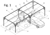
Figure 1 : Perspective view of an exemplary embodiment of the invention. -
Figure 2 : Rear view of the exemplary embodiment, focused on the carriage. - Next, an embodiment of the invention is briefly described, as an illustrative and nonlimiting example thereof.
- The vehicle charging station shown in the figures is based on a structure (1), which carries a set of sensors (2) for the presence of vehicles and people. The sensors can be traditional, infrared cameras or induction sensors for the presence of vehicles (
Figure 1 ). They can also be NFC detectors or similar for detecting labels or objects carried by the vehicle or people, which will be located precisely thanks to triangulation. The sensors (2) monitor an open area where parking spaces (3) are defined for the vehicles to be recharged and for the passage of people. The structure (1) is preferably a roofing to protect vehicles and people from the weather, to place sensitive equipment out of reach of people (mainly children) and to be able to place photovoltaic panels to power auxiliary equipment and assist, where appropriate, the charging of vehicles. - The station further comprises a high power recharging device (11), of 100-300 kW, which conditions the power supplied to the recharging conditions. The recharging device (11) is mounted on a carriage (4) movable on a guideway (5) arranged on one side of the parking spaces (3). The carriage (4) also carries a monitoring switchboard (6) and a robotic arm (7). The carriage (4) comprises a position sensor, such as a laser distance meter to measure the distance to a fixed point at one or both ends of the guideway (5).
- The switchboard (6) supplies the power to all the components, taking it from connector-bars (9) that are out of the reach of the users (at height in
Figure 1 ) for safety purposes. The switchboard (6) also includes safety equipment (switches, relays... and automatons that provide the entire device with the intelligence necessary for its proper functioning and safety). - The robotic arm (7) is responsible for autonomously recharging the vehicle, avoiding at all times the need for intervention of people. This ensures that the personnel do not handle electrical elements of such high power as the aforementioned. The robotic arm (7) will comprise a claw at its end to perform the automatic connection to and disconnection from a charge controller (8) or charging pole connectable to each vehicle.
- Each parking space (3) will have a charging controller (8), which forms the recharging stall. It comprises a hose (10) with a head to connect to the vehicle and detect the charge needs and its maximum capacity. The charge controller (8) may comprise a control console for the user to identify their vehicle (mainly its model), for example indicating the license plate for the charge controller (8) to look it up in an internal or external database. The license plate can also be detected by the sensors (2). The vehicle model may also be identified by an object or code carried by the user or vehicle. The system will also proceed to make pay the energy and notify the user of the start and end of the charge.
- The user will connect the car socket to the charge controller (8), which will initially be with the minimum operating energy of its elements, which is insufficient for the charge. The charge controller (8) will measure the need for the vehicle and report it to the service management system. When it considers that it is time to charge, it will bring the carriage (4) closer and connect the robotic arm (7) to the charge controller (8) to provide the energy with high power. Once finished, or if the user interrupts the management operation, the robotic arm (7) will be disconnected and switched to another charge controller (8). The same charge controller (8) can serve two adjacent parking spaces (3).
Claims (8)
- Electric vehicle charging station, comprising an area with a number of parking spaces (3) and a nearby structure (1), characterised in that: the structure (1) carries a series of sensors (2) for the presence of vehicles that monitor the parking spaces (3) and comprises a guideway (5) close to the parking spaces (3) on which a single carriage (4) runs carrying:- a monitoring switchboard (6) for supplying high power from one or more connector-bars (9);- a recharging device (11) that transforms the power to the conditions required for recharging, and is connected to a conductor carried by a robotic arm (7);- a carriage position sensor (4);- and a number of fixed charge controllers (8), with a hose (10) with connection head to the charge port of the vehicles adjacent to each parking space (3) so that the charge controllers (8) are disconnected from the charge mains and the robotic arm (7) is configured to connect the conductor to the charge controllers (8) in succession.
- Charging station, characterised in that the structure (1) is a roofing and the sensors (2) are at the top.
- Charging station according to claim 2, characterised in that the connector-bars (9) are arranged at height.
- Charging station according to claim 1, characterised in that the position sensor is a laser distance meter to measure the distance to a fixed point at one or both ends of the guideway (5).
- Charging station according to claim 1, characterised in that the sensors (2) comprise vehicle identification means.
- Charging station according to claim 1, characterised in that at least one charging controller (8) comprises two hoses (10) for two adjacent parking spaces (3).
- Charging station according to claim 1, characterised in that the charge controllers (8) comprise a vehicle model identification system.
- Charging station according to claim 1, characterised in that the charge controllers (8) comprise a sensor for the charge present in the vehicle.
Applications Claiming Priority (2)
| Application Number | Priority Date | Filing Date | Title |
|---|---|---|---|
| ES202030911U ES1249144Y (en) | 2020-05-14 | 2020-05-14 | VEHICLE CHARGING STATION |
| PCT/ES2021/070052 WO2021229115A1 (en) | 2020-05-14 | 2021-01-25 | Vehicle charging station |
Publications (2)
| Publication Number | Publication Date |
|---|---|
| EP4151371A1 true EP4151371A1 (en) | 2023-03-22 |
| EP4151371A4 EP4151371A4 (en) | 2024-06-05 |
Family
ID=71401454
Family Applications (1)
| Application Number | Title | Priority Date | Filing Date |
|---|---|---|---|
| EP21804878.3A Pending EP4151371A4 (en) | 2020-05-14 | 2021-01-25 | VEHICLE CHARGING STATION |
Country Status (3)
| Country | Link |
|---|---|
| EP (1) | EP4151371A4 (en) |
| ES (1) | ES1249144Y (en) |
| WO (1) | WO2021229115A1 (en) |
Families Citing this family (3)
| Publication number | Priority date | Publication date | Assignee | Title |
|---|---|---|---|---|
| IT202000029687A1 (en) * | 2020-12-03 | 2022-06-03 | S Cube Srl | SYSTEM FOR THE AUTOMATIC CONNECTION AND/OR DISCONNECTION OF THE ELECTRICITY SUPPLY AND/OR THE DATA CONNECTION FOR REFRIGERATED CONTAINERS |
| CN114475402A (en) * | 2022-01-28 | 2022-05-13 | 能翊行(苏州)科技有限公司 | Mobile charging system |
| US12547177B2 (en) | 2023-03-03 | 2026-02-10 | Ford Global Technologies, Llc | Systems and methods for managing a robotic charging system of a manufacturing environment |
Family Cites Families (6)
| Publication number | Priority date | Publication date | Assignee | Title |
|---|---|---|---|---|
| US8810198B2 (en) * | 2011-09-02 | 2014-08-19 | Tesla Motors, Inc. | Multiport vehicle DC charging system with variable power distribution according to power distribution rules |
| DE102014226357A1 (en) | 2014-12-18 | 2016-06-23 | Robert Bosch Gmbh | Charging station and method for automatically charging an electrical energy store in a vehicle |
| DE102015225986B4 (en) * | 2015-12-18 | 2019-07-04 | Kuka Deutschland Gmbh | A method for performing power supply operations between at least one power supply unit and a plurality of motor vehicles to be supplied with energy |
| US10828770B2 (en) * | 2017-08-24 | 2020-11-10 | GM Global Technology Operations LLC | Power delivery system for electric vehicle charging station |
| CN208993497U (en) * | 2018-08-13 | 2019-06-18 | 青岛海汇德电气有限公司 | A kind of charging system |
| CN209426594U (en) * | 2018-11-28 | 2019-09-24 | 新宜能电气科技有限公司 | Mobile shared charging equipment of electric automobile |
-
2020
- 2020-05-14 ES ES202030911U patent/ES1249144Y/en active Active
-
2021
- 2021-01-25 WO PCT/ES2021/070052 patent/WO2021229115A1/en not_active Ceased
- 2021-01-25 EP EP21804878.3A patent/EP4151371A4/en active Pending
Also Published As
| Publication number | Publication date |
|---|---|
| WO2021229115A1 (en) | 2021-11-18 |
| ES1249144Y (en) | 2020-09-28 |
| ES1249144U (en) | 2020-07-07 |
| EP4151371A4 (en) | 2024-06-05 |
Similar Documents
| Publication | Publication Date | Title |
|---|---|---|
| US10696174B2 (en) | Electric vehicle charging interface | |
| US20200317078A1 (en) | Automatic charging system for intelligent driving electric vehicles and charging method thereof | |
| EP4151371A1 (en) | Vehicle charging station | |
| CN111201691B (en) | Mobile charging unit, in particular for electric vehicles, and its management system for the on-demand delivery of electricity | |
| KR102567625B1 (en) | Electric vehicle charging system and electric vehicle charging management system | |
| CN110077254A (en) | The charging method of electronic autonomous body | |
| KR20160138913A (en) | Automated Robotic Battery Tug | |
| US10464428B2 (en) | Battery-backed DC fast charging system | |
| US20190217737A1 (en) | Autonomous robotic chargers and electric vehicle charging system | |
| KR20150119389A (en) | Contactless electricity supply system | |
| EP4249318A1 (en) | Battery swapping management system and method for battery swap station | |
| US20240132287A1 (en) | System and Method for Robotic Battery Exchange for Local Use Vehicles | |
| CN205160111U (en) | Electric vehicle charging system | |
| US20220266705A1 (en) | Function extension module for charging stations | |
| US20120105002A1 (en) | Method and apparatus for automated charging of electrically powered moving objects | |
| GB2525068A (en) | Transportable charging station | |
| US20200139834A1 (en) | Battery-backed dc fast charging system | |
| US12447845B2 (en) | Automated installation for charging electrical vehicles | |
| CN108790875B (en) | Bus charging management device and method | |
| ES1299504U (en) | VEHICLE CHARGING STATION (Machine-translation by Google Translate, not legally binding) | |
| JP3309864B2 (en) | Battery charger for mobile vehicles | |
| US12286021B1 (en) | Suspended battery charging station | |
| KR102910275B1 (en) | Electric vehicle charging management system based on a mobile charging device linked to parking facilities and thereof method | |
| CN108749613B (en) | Bus remote charging management device and control method | |
| KR20250146868A (en) | vehicle charging device |
Legal Events
| Date | Code | Title | Description |
|---|---|---|---|
| STAA | Information on the status of an ep patent application or granted ep patent |
Free format text: STATUS: THE INTERNATIONAL PUBLICATION HAS BEEN MADE |
|
| PUAI | Public reference made under article 153(3) epc to a published international application that has entered the european phase |
Free format text: ORIGINAL CODE: 0009012 |
|
| STAA | Information on the status of an ep patent application or granted ep patent |
Free format text: STATUS: REQUEST FOR EXAMINATION WAS MADE |
|
| 17P | Request for examination filed |
Effective date: 20221104 |
|
| AK | Designated contracting states |
Kind code of ref document: A1 Designated state(s): AL AT BE BG CH CY CZ DE DK EE ES FI FR GB GR HR HU IE IS IT LI LT LU LV MC MK MT NL NO PL PT RO RS SE SI SK SM TR |
|
| DAV | Request for validation of the european patent (deleted) | ||
| DAX | Request for extension of the european patent (deleted) | ||
| A4 | Supplementary search report drawn up and despatched |
Effective date: 20240506 |
|
| RIC1 | Information provided on ipc code assigned before grant |
Ipc: B60L 53/67 20190101ALI20240429BHEP Ipc: H02J 7/00 20060101ALI20240429BHEP Ipc: B60L 53/65 20190101ALI20240429BHEP Ipc: B60L 53/35 20190101ALI20240429BHEP Ipc: B60L 53/31 20190101ALI20240429BHEP Ipc: B60L 53/30 20190101ALI20240429BHEP Ipc: B25J 11/00 20060101ALI20240429BHEP Ipc: B60L 53/14 20190101ALI20240429BHEP Ipc: B25J 5/02 20060101AFI20240429BHEP |
|
| GRAP | Despatch of communication of intention to grant a patent |
Free format text: ORIGINAL CODE: EPIDOSNIGR1 |
|
| STAA | Information on the status of an ep patent application or granted ep patent |
Free format text: STATUS: GRANT OF PATENT IS INTENDED |
|
| RIC1 | Information provided on ipc code assigned before grant |
Ipc: B25J 5/02 20060101AFI20260123BHEP Ipc: H02J 7/70 20260101ALI20260123BHEP Ipc: B60L 53/14 20190101ALI20260123BHEP Ipc: B25J 11/00 20060101ALI20260123BHEP Ipc: B60L 53/30 20190101ALI20260123BHEP Ipc: H02J 7/40 20260101ALI20260123BHEP Ipc: B60L 53/31 20190101ALI20260123BHEP Ipc: B60L 53/35 20190101ALI20260123BHEP Ipc: B60L 53/65 20190101ALI20260123BHEP Ipc: H02J 7/00 20060101ALI20260123BHEP Ipc: B60L 53/67 20190101ALI20260123BHEP |
|
| INTG | Intention to grant announced |
Effective date: 20260210 |