EP4151185A1 - Console and foot control unit for a medical treatment system and medical treatment system for same - Google Patents
Console and foot control unit for a medical treatment system and medical treatment system for same Download PDFInfo
- Publication number
- EP4151185A1 EP4151185A1 EP22196208.7A EP22196208A EP4151185A1 EP 4151185 A1 EP4151185 A1 EP 4151185A1 EP 22196208 A EP22196208 A EP 22196208A EP 4151185 A1 EP4151185 A1 EP 4151185A1
- Authority
- EP
- European Patent Office
- Prior art keywords
- control unit
- console
- foot control
- medical treatment
- electrical
- Prior art date
- Legal status (The legal status is an assumption and is not a legal conclusion. Google has not performed a legal analysis and makes no representation as to the accuracy of the status listed.)
- Granted
Links
- 238000011282 treatment Methods 0.000 title claims abstract description 51
- 230000013011 mating Effects 0.000 claims description 14
- 238000004891 communication Methods 0.000 claims description 13
- 239000012530 fluid Substances 0.000 description 13
- 230000002262 irrigation Effects 0.000 description 6
- 238000003973 irrigation Methods 0.000 description 6
- 238000000034 method Methods 0.000 description 4
- 230000006870 function Effects 0.000 description 3
- 239000000463 material Substances 0.000 description 3
- 208000002177 Cataract Diseases 0.000 description 2
- 230000008878 coupling Effects 0.000 description 2
- 238000010168 coupling process Methods 0.000 description 2
- 238000005859 coupling reaction Methods 0.000 description 2
- 238000013461 design Methods 0.000 description 2
- 230000000694 effects Effects 0.000 description 2
- 238000004146 energy storage Methods 0.000 description 2
- 230000001939 inductive effect Effects 0.000 description 2
- 239000002245 particle Substances 0.000 description 2
- 230000002093 peripheral effect Effects 0.000 description 2
- 238000001356 surgical procedure Methods 0.000 description 2
- 230000005540 biological transmission Effects 0.000 description 1
- 238000006243 chemical reaction Methods 0.000 description 1
- 238000004140 cleaning Methods 0.000 description 1
- 239000002131 composite material Substances 0.000 description 1
- 238000005260 corrosion Methods 0.000 description 1
- 230000007797 corrosion Effects 0.000 description 1
- 230000001419 dependent effect Effects 0.000 description 1
- 238000001514 detection method Methods 0.000 description 1
- 238000011161 development Methods 0.000 description 1
- 230000018109 developmental process Effects 0.000 description 1
- 238000010586 diagram Methods 0.000 description 1
- 239000003814 drug Substances 0.000 description 1
- 238000005516 engineering process Methods 0.000 description 1
- 238000011010 flushing procedure Methods 0.000 description 1
- 238000005259 measurement Methods 0.000 description 1
- 239000002184 metal Substances 0.000 description 1
- 230000009993 protective function Effects 0.000 description 1
Images


Classifications
-
- A—HUMAN NECESSITIES
- A61—MEDICAL OR VETERINARY SCIENCE; HYGIENE
- A61F—FILTERS IMPLANTABLE INTO BLOOD VESSELS; PROSTHESES; DEVICES PROVIDING PATENCY TO, OR PREVENTING COLLAPSING OF, TUBULAR STRUCTURES OF THE BODY, e.g. STENTS; ORTHOPAEDIC, NURSING OR CONTRACEPTIVE DEVICES; FOMENTATION; TREATMENT OR PROTECTION OF EYES OR EARS; BANDAGES, DRESSINGS OR ABSORBENT PADS; FIRST-AID KITS
- A61F9/00—Methods or devices for treatment of the eyes; Devices for putting-in contact lenses; Devices to correct squinting; Apparatus to guide the blind; Protective devices for the eyes, carried on the body or in the hand
- A61F9/007—Methods or devices for eye surgery
- A61F9/00736—Instruments for removal of intra-ocular material or intra-ocular injection, e.g. cataract instruments
-
- A—HUMAN NECESSITIES
- A61—MEDICAL OR VETERINARY SCIENCE; HYGIENE
- A61B—DIAGNOSIS; SURGERY; IDENTIFICATION
- A61B17/00—Surgical instruments, devices or methods, e.g. tourniquets
-
- A—HUMAN NECESSITIES
- A61—MEDICAL OR VETERINARY SCIENCE; HYGIENE
- A61B—DIAGNOSIS; SURGERY; IDENTIFICATION
- A61B17/00—Surgical instruments, devices or methods, e.g. tourniquets
- A61B2017/00017—Electrical control of surgical instruments
- A61B2017/00199—Electrical control of surgical instruments with a console, e.g. a control panel with a display
-
- A—HUMAN NECESSITIES
- A61—MEDICAL OR VETERINARY SCIENCE; HYGIENE
- A61B—DIAGNOSIS; SURGERY; IDENTIFICATION
- A61B17/00—Surgical instruments, devices or methods, e.g. tourniquets
- A61B2017/00017—Electrical control of surgical instruments
- A61B2017/00221—Electrical control of surgical instruments with wireless transmission of data, e.g. by infrared radiation or radiowaves
-
- A—HUMAN NECESSITIES
- A61—MEDICAL OR VETERINARY SCIENCE; HYGIENE
- A61B—DIAGNOSIS; SURGERY; IDENTIFICATION
- A61B17/00—Surgical instruments, devices or methods, e.g. tourniquets
- A61B2017/00477—Coupling
-
- A—HUMAN NECESSITIES
- A61—MEDICAL OR VETERINARY SCIENCE; HYGIENE
- A61B—DIAGNOSIS; SURGERY; IDENTIFICATION
- A61B17/00—Surgical instruments, devices or methods, e.g. tourniquets
- A61B2017/00973—Surgical instruments, devices or methods, e.g. tourniquets pedal-operated
-
- A—HUMAN NECESSITIES
- A61—MEDICAL OR VETERINARY SCIENCE; HYGIENE
- A61B—DIAGNOSIS; SURGERY; IDENTIFICATION
- A61B90/00—Instruments, implements or accessories specially adapted for surgery or diagnosis and not covered by any of the groups A61B1/00 - A61B50/00, e.g. for luxation treatment or for protecting wound edges
- A61B90/50—Supports for surgical instruments, e.g. articulated arms
-
- A—HUMAN NECESSITIES
- A61—MEDICAL OR VETERINARY SCIENCE; HYGIENE
- A61F—FILTERS IMPLANTABLE INTO BLOOD VESSELS; PROSTHESES; DEVICES PROVIDING PATENCY TO, OR PREVENTING COLLAPSING OF, TUBULAR STRUCTURES OF THE BODY, e.g. STENTS; ORTHOPAEDIC, NURSING OR CONTRACEPTIVE DEVICES; FOMENTATION; TREATMENT OR PROTECTION OF EYES OR EARS; BANDAGES, DRESSINGS OR ABSORBENT PADS; FIRST-AID KITS
- A61F9/00—Methods or devices for treatment of the eyes; Devices for putting-in contact lenses; Devices to correct squinting; Apparatus to guide the blind; Protective devices for the eyes, carried on the body or in the hand
Definitions
- the invention relates to a console for a medical treatment system, in particular an ophthalmic surgical system for treating an eye, with a console housing and a control unit for controlling a medical treatment instrument, a foot control unit being able to be wirelessly coupled to the control unit, and the console housing having at least one side wall.
- the invention also relates to a foot control unit for a medical treatment system, in particular an ophthalmic surgical system for treating an eye, with a housing, an electrical energy store arranged in the housing, an actuator that can be actuated by means of a foot, a communication unit for wireless communication with a console of the medical treatment system, and a charging unit for charging the electrical energy store.
- the invention also relates to a medical treatment system, in particular an ophthalmic surgical system, for the treatment of an eye, with at least one medical treatment instrument, a console for connecting and operating the medical treatment instrument in an intended operation, a foot control unit for at least partially controlling the intended operation of the medical Treatment instrument, wherein the foot control unit can be coupled wirelessly to the console and has an electrical energy store for supplying the foot control unit with electrical energy at least during the intended operation of the medical treatment system.
- a medical treatment system in particular an ophthalmic surgical system, for the treatment of an eye, with at least one medical treatment instrument, a console for connecting and operating the medical treatment instrument in an intended operation, a foot control unit for at least partially controlling the intended operation of the medical Treatment instrument, wherein the foot control unit can be coupled wirelessly to the console and has an electrical energy store for supplying the foot control unit with electrical energy at least during the intended operation of the medical treatment system.
- Medical treatment systems serve to be able to carry out a wide variety of treatments, for example operations, on a body of a living being, for example a human being or an animal.
- a medical treatment instrument is often used for this purpose, which can be guided manually or by means of a robot during an operation.
- the medical treatment instrument it is often necessary to supply the medical treatment instrument with electrical energy, one or more treatment fluids and operating data.
- This purpose is usually served by the console with which the medical treatment instrument can be coupled at least during normal operation.
- the console is thus designed to connect and operate the medical treatment instrument.
- the console usually has a control unit for controlling the medical treatment instrument.
- the control unit is in communication with the medical treatment element in order, for example, to transmit control data to the treatment instrument, or also to receive and evaluate operating data or measurement data from the medical treatment instrument.
- the console also makes it possible to act on the control unit in order to be able to implement the desired intended operation of the medical treatment instrument.
- the console can have an input unit that enables a surgeon, for example, to be able to make settings with regard to the desired intended operation.
- the input unit can, for example, be designed so that the operator can make a manual input.
- an input unit in the manner of a foot control unit can be provided, which provides a control signal for the control unit of the console depending on an actuation by means of a foot.
- the foot control unit can be part of the console or be designed as a separate unit.
- the foot control unit can be coupled to the console in a definable manner.
- One or more lines are often provided for this purpose, which are used, for example, to supply the foot control unit with electrical energy and/or to transmit data or signals. Such lines often prove to be disadvantageous during use of the medical treatment system. For this reason, for example, revealed the U.S. 2006/0219049 A1 a footswitch for controlling an operating system.
- the foot switch detects a foot switch mechanical input and provides a control signal for the medical instrument via a wireless communication device.
- the foot control unit has its own electrical energy store, which provides electrical energy for the intended operation.
- the electrical energy store is usually formed by a rechargeable battery.
- U.S. 2004/0212344 A1 an apparatus and method for maintaining a defibrillator battery charge and optional communications.
- U.S. 8,565,839 B2 a power management for wireless devices.
- Ophthalmic surgical systems as well as methods for their operation, are also known in the prior art, so that there is no need for separate printed evidence in this regard either.
- Various surgical techniques are known for treating clouding of the lens of the eye, also referred to in medicine as cataracts.
- the most widespread is phacoemulsification, in which a thin hollow needle is inserted into a capsular bag in which the lens of the eye is located and stimulated to ultrasonic vibrations.
- the lens can be emulsified by means of the vibrating hollow needle, in which case the lens particles that are released can be suctioned off via an aspiration line using a pump.
- a flushing fluid also called irrigation fluid, is supplied.
- the lens particles are aspirated along with the fluid as aspiration fluid.
- a handpiece is used as the medical treatment instrument, which has the hollow needle and is connected to a corresponding console of the ophthalmic surgical system at least during normal operation.
- the console provides the irrigation fluid and also a drain for the aspiration fluid.
- the console also provides electrical energy for the intended operation of the handpiece.
- the operation of the handpiece can be controlled by means of a control unit of the console. Since the operator's hand is usually not available for controlling inputs for the operation to be carried out, a foot control is used to control the operation of the handpiece. For this purpose, the foot control unit is coupled with the console accordingly.
- the invention is based on the object of improving the arrangement of the foot control unit, in particular outside of the intended operation, in particular also of an energy supply.
- the invention proposes in particular that the side wall has a contact surface for arranging the foot control unit in a non-use position, the contact surface being inclined relative to a horizontal plane at least in the area where the foot control unit is arranged, in order to of the contact surface by the weight of the foot control unit causing the foot control unit to rest against the contact surface, the side wall in the area of the contact surface having a console-side connection unit for detachably connecting the foot control unit to the console.
- the invention proposes in particular that the housing has a connection area for detachably arranging the foot control unit in a non-use position on a contact surface of the console, the connection area having a foot control unit-side connection unit for detachable connection of the foot control unit to the console.
- the invention proposes in particular that at least the console or the foot control unit is designed according to the invention.
- the invention is based, among other things, on the idea that the foot control unit is preferably designed to be completely wireless and does not require a connection via a cable either in normal operation or in the non-use position. At the same time, it can be ensured, in particular for the non-use position, that the foot control unit is easily arranged at a predetermined location and is therefore easily available for the intended use in the medical treatment system.
- the inclined contact surface of the console makes it possible for the foot control unit to already be in position when it is arranged on the console due to its weight on the contact surface of the console and thus a reliable connection between the console and the foot control unit can be achieved so that the console can be moved together with the foot control unit outside of the intended operation.
- the foot control can be carried by connecting it to the console.
- a handling unit can therefore be created that simplifies use. It is no longer necessary to provide separate storage locations for the foot control units.
- the provision of a console for medical treatment also allows the foot control unit to be provided at the same time.
- the invention makes it possible to individually assign a wireless foot control unit to a console. As a result, function-specific features of a respective medical treatment system can also be reliably implemented in a simple manner. Overall, the invention thus makes it possible to improve the handling of a wireless foot control unit.
- the side wall of the housing which provides the contact surface, can be designed as a closed side wall. In addition, however, it can also at least partially have one or more through-openings. The through openings can also be provided in the area of the contact surface.
- the housing, in particular the side wall can be formed from a suitable stable material, for example metal, plastic, a composite material, combinations thereof and/or the like.
- An electrically conductive housing has the advantage that, on the one hand, the emission of interference on the console side with regard to electromagnetic compatibility can be kept low or even avoided and, on the other hand, an influence on the console, in particular the control unit, by electromagnetic signals from outside the console can be dampened or suppressed . The reliability of the function of the medical treatment system can thereby be improved.
- the side wall has the console-side connection unit for detachably connecting the foot control unit to the console.
- a retaining strip can be arranged in a lower area of the contact surface.
- the retaining bar can also be combined with other connecting elements such as pins, recesses and the like.
- the foot control unit does not need to be accommodated in the manner of a receiving pocket. This makes the foot control unit particularly easy to access and connect to the console.
- the inclination of the contact surface relative to the horizontal plane is preferably such that the contact surface faces away from the horizontal plane in the area of the foot of the console. A slight inclination to the vertical is sufficient, for example in a range from about 3° to about 15°, preferably in a range from about 5° to about 10°.
- the console has a charging unit for charging an electrical energy store of the foot control unit, the contact surface having a charging connection with at least two electrical contacts for contacting corresponding counter-contacts of the foot control unit.
- the energy store of the foot control unit can be charged in the non-use position in which the foot control unit is arranged on the console.
- the foot control unit can also be made ready for use or kept ready for use as intended. This can be achieved without additional electrical connection means having to be actuated in order to enable charging of the electrical energy store via the console. Only the arrangement of the foot control unit on the contact surface of the console can at the same time also realize an electrical coupling between the charging unit of the console and the electrical energy store of the foot control unit.
- the charging unit can only be formed by an electrical connection to an electrical energy source such as the public energy supply network or the like.
- the charging unit preferably also includes an energy converter in order to be able to supply electrical energy to the energy store as required. Energy conversion in the foot control unit can be saved as a result.
- the energy converter can, for example, implement a voltage adjustment between the voltage source and the energy store.
- at least two electrical contacts are provided in the area of the contact surface, so that when the foot control unit is arranged on the console, an electrical connection of the foot control unit to the console, in particular to its charging unit, can also be implemented.
- the foot control unit has corresponding mating contacts.
- the electrical contacts can be designed, for example, as pin contacts that protrude outwards from the plane of the contact surface.
- the electrical contacts can be resiliently mounted, for example. Further contacts can of course also be provided, for example in order to be able to detect the foot control unit, in particular its correct position on the contact surface.
- the contact surface has a peripheral collar that protrudes from the contact surface and surrounds the electrical contacts.
- the collar can be formed from the same material as the side wall.
- the collar may be integral with the sidewall. Alternatively, however, the collar can also be designed as a separate component which is fastened to the side wall at the predetermined position.
- the collar can have a definable inner and/or outer contour in the circumferential direction.
- the collar preferably has a height that corresponds at least to the maximum height of the electrical contacts.
- the connection unit has at least two retaining pins for arranging in corresponding receiving openings of the foot control unit, which are arranged at least horizontally spaced from each other.
- the holding pins allow the foot control unit to be held better on the console. In particular, a particularly simple arrangement on the console and removal from the console can be achieved.
- the retaining pins are preferably dimensioned with regard to their length in such a way that they do not protrude through the foot control unit when it is arranged on the console.
- the holding pins can have a definable contour in relation to a cross section, which is adapted to an inner contour of the receiving openings of the foot control unit. This allows coding to be achieved so that not just any foot control unit can be combined with any console.
- the retaining pins are preferably of essentially the same design. In addition, it is preferred if the retaining pins protrude essentially perpendicularly from the support surface.
- the retaining pins can be made of the same material as the side wall. In particular, they can be formed in one piece with the side wall. However, it can also be provided that the retaining pins are separate parts that can be connected to the side wall, for example by means of a screw connection, a rivet connection and/or the like.
- the electrical contacts are designed as resilient electrical pin contacts. As a result, a reliable electrical contact can be guaranteed even with variable positions of the mating contacts of the foot control unit.
- connection area has at least two receiving openings for receiving corresponding retaining pins of the console, which are arranged at least horizontally spaced from one another.
- the retaining pins engaging in the receiving openings can also ensure that the foot control unit can be protected against twisting due to the effect of external forces when it is arranged on the console.
- the charging unit has a charging connection with at least two electrical counter-contacts arranged on the connection area for making contact with corresponding electrical contacts of the console.
- the charging unit can basically be constituted only by electrical connection.
- the charging unit can also have an electrical energy converter, by means of which an electrical voltage can be adapted to the electrical energy store.
- the charging unit can be designed for unidirectional power supply.
- the charging unit is preferably electrically coupled to the electrical energy store.
- connection area has a plateau for arranging in a recess provided by the collar, the electrical Mating contacts are arranged in the region of a plateau level of the plateau. It can thereby be achieved that the electrical connection is protected from external influences when it is arranged on the console.
- the extra-low voltage can, for example, comply with Directive 2001/95/EC of the European Parliament and of the Council of December 3, 2001 on general product safety. This is preferably an AC voltage whose effective value is less than approximately 50 V, or a DC voltage which is less than approximately 75 V.
- the electrical mating contacts are preferably formed by flat, electrically conductive elements that can make good electrical contact with the electrical contacts of the console. They are particularly advantageously designed for contacting contact pins.
- console according to the invention and the foot control unit according to the invention naturally also apply equally to the medical treatment system equipped with the console according to the invention and the foot control unit according to the invention and vice versa.
- FIG. 1 1 shows, in a schematic block diagram representation, an ophthalmosurgical system 1 as a medical treatment system, which is used to treat an eye 2.
- the ophthalmic surgical system 1 has a medical treatment instrument, which is formed by a handpiece 3 in the present case.
- the ophthalmosurgical system 1 has a console 4 for connecting and operating the handpiece 3 in an intended operation.
- the ophthalmosurgical system 1 has a foot control unit 5, which in the present case is designed as a foot pedal.
- the foot control unit 5 can be coupled wirelessly to the console 4 via a radio link 11 and has an electrical energy store 6 for supplying the foot control unit 5 with electrical energy at least during the intended operation of the handpiece 3 .
- the console 4 also has a control unit 7 and fluidic and electrical supply units 8 which serve, among other things, to supply an irrigation fluid to the handpiece 3 via an irrigation line 9 and to remove an aspiration fluid from the handpiece 3 via an aspiration line 10 .
- the foot control unit 5 is designed to be wireless, which is why it is supplied with electrical energy from the electrical energy store 6 at least during normal operation.
- the foot control unit 5 is in communication with the control unit 7 via the wireless radio link 11 during normal operation, so that an operating state of the handpiece 3 can be set at least partially.
- the console 4 has a console housing 12 in which the elements or units of the console 4 are arranged.
- the console housing 12 has a side wall 13 which forms a rear side of the console 4 in the present case.
- the side wall 13 has a contact surface 14 which is used to arrange the foot control unit 5 in a non-use position.
- the contact surface 14 is inclined relative to a horizontal plane in the area where the foot control unit 5 is arranged in order to cause the foot control unit 5 to rest against the contact surface 14 when the foot control unit 5 is arranged on the contact surface 14 due to the weight of the foot control unit 5 .
- the contact surface 14 is planar or flat, in particular non-curved.
- the side wall 13 has a console-side connection unit 15 in the area of the contact surface 14 for detachably connecting the foot control unit 5 to the console 4 .
- the console-side connecting unit 15 has two retaining pins 16 for arranging in corresponding receiving openings of the foot control unit 5, which are arranged horizontally spaced from each other.
- the retaining pins 16 are arranged essentially at approximately the same height in relation to a horizontal floor. In alternative configurations, however, this can also deviate.
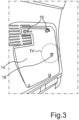
- 3 shows a corresponding enlarged representation of a detail III in 2 .
- 4 shows in a schematic plan view an enlarged representation of a region IV in 3 .
- the contact surface 14 has a peripheral collar 22 which protrudes from the contact surface 14 and surrounds the electrical contacts 19 , 20 , 21 .
- the console 4 also has a charging unit 17 for charging the electrical energy store 6 of the foot control unit 5 .
- the contact surface 14 has a charging connection 18 of the charging unit 17 with three electrical contacts 19, 20, 21 for contacting corresponding electrical mating contacts 31, 32, 33 of the foot control unit 5 ( figure 5 ).
- the electrical contacts 19 , 20 , 21 are firmly connected to the contact surface 14 .
- the electrical contacts 19, 20, 21, which are designed as pin contacts can also be designed as resilient electrical contacts.
- the electrical contacts 19, 20, 21 are electrically isolated from the side wall 13 arranged.
- the electrical contacts 19, 20, 21 are connected to the charging unit 17.
- FIG. 5 shows a section of a rear side of the foot control unit 5 in a schematic plan view.
- the foot control unit 5 has a housing 23 ( 7 ), an electrical energy storage device 6 arranged in the housing 23 ( 1 ), a foot-operable actuator 24 ( 1 ), a communication unit 26 for wireless communication via radio with the console 4 of the ophthalmic surgical system 1 and a charging unit 25 for charging the electrical energy store 6 on ( 1 ).
- the housing 23 has a connection area 27 for detachably arranging the foot control unit 5 in a non-use position on the contact surface 14 of the console 4 ( 6 ).
- the connection area 27 has a foot control unit-side connection unit 36 for detachably connecting the foot control unit 5 to the console 4 .
- the connection area 27 has two receiving openings 30 for receiving corresponding retaining pins 16 of the console 4, which are separated from each other at least horizontally are spaced apart.
- the foot control unit 5 can be arranged on the console 4 in a simple manner, with the retaining pins 16 being inserted into the receiving openings 30 designed as blind openings. Due to the simultaneous inclined position of the contact surface 14, a reliable connection with the console 4 can thus be achieved by the weight of the foot control unit 5, which can be detached.
- the charging unit 25 has a charging connection 28 which has the three electrical mating contacts 31 , 32 , 33 arranged on the connection area 27 for contacting corresponding electrical contacts 19 , 20 , 21 of the console 4 .
- the electrical counter-contacts 31, 32, 33 are designed here as flat, essentially circular contact plates, which are connected to the charging unit 25 via electrical lines (not shown).
- the connecting area 27 has the plateau 35 for arranging in a recess provided by the collar 22 .
- the electrical mating contacts 31 , 32 , 33 are arranged in the area of a plateau plane 34 of the plateau 35 .
- the arrangement corresponds to the arrangement of the electrical contacts 19, 20, 21, so that an electrical connection can be achieved by making contact when the foot control unit 5 is arranged on the console 4. In the present case, they are resiliently mounted, but in alternative configurations they can also be firmly connected to the plateau 35 .
- the invention makes it possible in particular to equip a modern workplace for cataract surgery.
- the units or systems of the ophthalmic surgical system are networked with each other to enable good performance and simple, intuitive operation.
- the invention makes it possible to at least partially avoid cable connections or hose connections for fluids. In particular, electrical cable connections as well as communication lines can be avoided almost entirely.
- a wireless communication connection to the console 4 is provided for the foot control device 5, also called the foot switch pedal (FSP).
- FSP foot switch pedal
- the foot control device or the foot control unit 5 also has an at least partially independent energy supply, which is why the electrical energy store 6 is provided, which is usually designed as an accumulator.
- the foot control device 5 can be stored in association with the console 4 thanks to the invention.
- the aforementioned connection technology allows a manageable unit to be created from the console 4 and the foot control unit 5 outside of the intended operation, so that the corresponding devices for an ophthalmic surgical operation can be provided in a simple manner.
- the invention makes it possible to supply the foot control device 5, in particular its energy store 6, with electrical energy when it is arranged on the console 4 in the non-use position.
- the electrical contact connection proposed here a reliable wired, but at the same time wireless electrical connection can be achieved, so that a large amount of energy can also be transmitted in a short time in a simple manner. In this way, disturbances such as can occur, for example, in energy transmission using alternating magnetic fields can be largely avoided. This is particularly important for the medical field.
- the electrical mating contacts 31, 32, 33 are glued into the housing 23 on an underside. Alternatively, they can also be injected if the housing 23 is formed from a plastic, for example.
- the electrical voltage between the counter-electrodes 31, 32, 33 and the electrical contacts 19, 20, 21 is approximately 15 V. This is a DC voltage.
- a charging current can be about 1 A, for example.
- a protective function can be achieved via the respective third electrical contact 19 or electrical mating contact 31, so that the supply voltage of 15 V is only made available if an electrical contact has been established via these two electrical contacts 19, 31. If an electrical contact cannot be made via these contacts, it can be provided that the electrical voltage is limited to approximately 3.3 V or even switched off completely.
- This can be detected by the charging unit 17, for which purpose the charging unit 25 applies a corresponding signal to the electrical counter-contact 31.
- the loading function can then be used, for example, via the electrical contacts 20, 21 or 32, 33 take place.
- the electrical voltage is provided as a safety extra-low voltage. This allows increased security to be achieved.
- the collar 22 interacts with the platform 35 when the foot control unit 5 is arranged on the console 4 .
- a centering can be achieved in this way if an inner contour of the recess provided by the collar 22 is chosen to be adapted to an outer contour of the plateau 35 .
- the electrical contacts or electrical counter-contacts can also be centered.
- the collar 22 can protect the electrical contacts 19 to 21 from external mechanical influences.
- the charging unit 17 be designed to evaluate an electrical potential on at least one of the electrical contacts 19 , 20 , 21 in order to detect that the foot control unit 5 has been arranged on the console 4 .
- This can be used so that the charging unit 17 only applies an electrical voltage to the electrical contacts 19, 20, 21 when a corresponding arrangement of the foot control unit 5 on the console 4 has been detected. This can improve electrical safety.
- potential differences between pairs of electrical contacts 19, 20, 21 can also be evaluated for detection.
Abstract
Die Erfindung betrifft eine Konsole (4) für ein medizinisches Behandlungssystem, mit einem Konsolengehäuse (12) und einer Steuereinheit (7) zum Steuern eines medizinischen Behandlungsinstruments (3), wobei eine Fußbedieneinheit (5) drahtlos mit der Steuereinheit (7) koppelbar ist, und das Konsolengehäuse (12) wenigstens eine Seitenwand (13) aufweist, die eine Anlagefläche (14) zum Anordnen der Fußbedieneinheit (5) in einer Nichtgebrauchsstellung aufweist, wobei die Anlagefläche (14) zumindest im Bereich der Anordnung der Fußbedieneinheit (5) gegenüber einer horizontalen Ebene geneigt ist, um beim Anordnen der Fußbedieneinheit (5) an der Anlagefläche (14) durch die Gewichtskraft der Fußbedieneinheit (5) ein Anliegen der Fußbedieneinheit (5) an der Anlagefläche (14) zu bewirken, wobei die Seitenwand (13) im Bereich der Anlagefläche (14) eine konsolenseitige Verbindungseinheit (15) zum lösbaren Verbinden der Fußbedieneinheit (5) mit der Konsole (4) aufweist. Ferner betrifft die Erfindung eine entsprechende Fußbedieneinheit (5) sowie ein medizinisches Behandlungssystem.

Description
Die Erfindung betrifft eine Konsole für ein medizinisches Behandlungssystem, insbesondere ein ophthalmochirurgisches System zur Behandlung eines Auges, mit einem Konsolengehäuse und einer Steuereinheit zum Steuern eines medizinischen Behandlungsinstruments, wobei eine Fußbedieneinheit drahtlos mit der Steuereinheit koppelbar ist, und das Konsolengehäuse wenigstens eine Seitenwand aufweist. Ferner betrifft die Erfindung eine Fußbedieneinheit für ein medizinisches Behandlungssystem, insbesondere ein ophthalmochirurgisches System zur Behandlung eines Auges, mit einem Gehäuse, einem im Gehäuse angeordneten elektrischen Energiespeicher, einem mittels eines Fußes betätigbaren Stellglied, einer Kommunikationseinheit zum drahtlosen Kommunizieren mit einer Konsole des medizinischen Behandlungssystems sowie einer Aufladeeinheit zum Aufladen des elektrischen Energiespeichers. Schließlich betrifft die Erfindung auch ein medizinisches Behandlungssystem, insbesondere ein ophthalmochirurgisches System, zur Behandlung eines Auges, mit zumindest einem medizinischen Behandlungsinstrument, einer Konsole zum Anschließen und Betreiben des medizinischen Behandlungsinstruments in einem bestimmungsgemäßen Betrieb, einer Fußbedieneinheit zum zumindest teilweisen Steuern des bestimmungsgemäßen Betriebs des medizinischen Behandlungsinstruments, wobei die Fußbedieneinheit drahtlos mit der Konsole koppelbar ist und einen elektrischen Energiespeicher zum Versorgen der Fußbedieneinheit mit elektrischer Energie zumindest während des bestimmungsgemäßen Betriebs des medizinischen Behandlungssystems aufweist.The invention relates to a console for a medical treatment system, in particular an ophthalmic surgical system for treating an eye, with a console housing and a control unit for controlling a medical treatment instrument, a foot control unit being able to be wirelessly coupled to the control unit, and the console housing having at least one side wall. The invention also relates to a foot control unit for a medical treatment system, in particular an ophthalmic surgical system for treating an eye, with a housing, an electrical energy store arranged in the housing, an actuator that can be actuated by means of a foot, a communication unit for wireless communication with a console of the medical treatment system, and a charging unit for charging the electrical energy store. Finally, the invention also relates to a medical treatment system, in particular an ophthalmic surgical system, for the treatment of an eye, with at least one medical treatment instrument, a console for connecting and operating the medical treatment instrument in an intended operation, a foot control unit for at least partially controlling the intended operation of the medical Treatment instrument, wherein the foot control unit can be coupled wirelessly to the console and has an electrical energy store for supplying the foot control unit with electrical energy at least during the intended operation of the medical treatment system.
Medizinische Behandlungssysteme, ophthalmochirurgische Systeme zur Behandlung eines Auges, Konsolen sowie auch Fußbedieneinheiten hierfür sind im Stand der Technik umfänglich bekannt, sodass es diesbezüglich eines gesonderten druckschriftlichen Nachweises nicht bedarf. Medizinische Behandlungssysteme dienen dazu, unterschiedlichste Behandlungen, beispielsweise Operationen, an einem Körper eines Lebewesens, beispielsweise dem Menschen oder einem Tier, durchführen zu können. Hierzu wird häufig ein medizinisches Behandlungsinstrument benutzt, welches manuell oder mittels eines Roboters während einer Operation geführt werden kann. Für den bestimmungsgemäßen Betrieb des medizinischen Behandlungsinstruments ist es häufig erforderlich, das medizinische Behandlungsinstrument mit elektrischer Energie, einem oder mehreren Behandlungsfluiden sowie Betriebsdaten zu versorgen. Diesem Zweck dient in der Regel die Konsole, mit der das medizinische Behandlungsinstrument zumindest während des bestimmungsgemäßen Betriebs gekoppelt werden kann. Die Konsole ist somit zum Anschließen und Betreiben des medizinischen Behandlungsinstruments ausgebildet.Medical treatment systems, ophthalmosurgical systems for the treatment of an eye, consoles and also foot control units for this are extensively known in the prior art, so that separate printed proof is not required in this regard. Medical treatment systems serve to be able to carry out a wide variety of treatments, for example operations, on a body of a living being, for example a human being or an animal. A medical treatment instrument is often used for this purpose, which can be guided manually or by means of a robot during an operation. For the intended operation of the medical treatment instrument, it is often necessary to supply the medical treatment instrument with electrical energy, one or more treatment fluids and operating data. This purpose is usually served by the console with which the medical treatment instrument can be coupled at least during normal operation. The console is thus designed to connect and operate the medical treatment instrument.
Zu diesem Zweck weist die Konsole in der Regel eine Steuereinheit zum Steuern des medizinischen Behandlungsinstruments auf. Die Steuereinheit steht mit dem medizinischen Behandlungselement in Kommunikationsverbindung, um beispielsweise Steuerdaten an das Behandlungsinstrument zu übermitteln, oder auch Betriebsdaten oder Messdaten vom medizinischen Behandlungsinstrument zu erhalten und auszuwerten. Die Konsole ermöglicht es darüber hinaus, auf die Steuereinheit einzuwirken, um den gewünschten bestimmungsgemäßen Betrieb des medizinischen Behandlungsinstruments realisieren zu können.For this purpose, the console usually has a control unit for controlling the medical treatment instrument. The control unit is in communication with the medical treatment element in order, for example, to transmit control data to the treatment instrument, or also to receive and evaluate operating data or measurement data from the medical treatment instrument. The console also makes it possible to act on the control unit in order to be able to implement the desired intended operation of the medical treatment instrument.
Zu diesem Zweck kann die Konsole eine Eingabeeinheit aufweisen, die es beispielsweise einem Operateur ermöglicht, Einstellungen bezüglich des gewünschten bestimmungsgemäßen Betriebs vornehmen zu können. Die Eingabeeinheit kann zum Beispiel dazu ausgebildet sein, dass der Operateur eine manuelle Eingabe vornehmen kann. Manuelle Eingaben sind jedoch bei bestimmten medizinischen Behandlungen nur schlecht oder sogar teilweise sogar unmöglich. Aus diesem Grund kann eine Eingabeeinheit nach Art einer Fußbedieneinheit vorgesehen sein, die abhängig von einer Betätigung mittels eines Fußes ein Steuersignal für die Steuereinheit der Konsole bereitstellt. Die Fußbedieneinheit kann dabei Bestandteil der Konsole sein oder auch als eine separate Einheit ausgebildet sein. Die Fußbedieneinheit kann für den bestimmungsgemäßen Betrieb mit der Konsole in vorgebbarer Weise gekoppelt werden. Häufig sind hierfür eine oder mehrere Leitungen vorgesehen, die beispielsweise der Versorgung der Fußbedieneinheit mit elektrischer Energie und/oder dem Übermitteln von Daten beziehungsweise Signalen dienen. Derartige Leitungen erweisen sich während der Nutzung des medizinischen Behandlungssystems häufig als nachteilig. Aus diesem Grund offenbart zum Beispiel die
Darüber hinaus ist es bekannt, dass die Fußbedieneinheit einen eigenen elektrischen Energiespeicher aufweist, der für den bestimmungsgemäßen Betrieb elektrische Energie bereitstellt. Der elektrische Energiespeicher ist in der Regel durch einen aufladbaren Akkumulator gebildet. In diesem Zusammenhang offenbart zum Beispiel die
Ophthalmochirurgische Systeme, sowie auch Verfahren zu deren Betrieb, sind im Stand der Technik ebenfalls bekannt, sodass es auch diesbezüglich eines gesonderten druckschriftlichen Nachweises nicht bedarf. Zur Behandlung einer Augenlinsentrübung, in der Medizin auch als Grauer Star bezeichnet, sind unterschiedliche chirurgische Techniken bekannt. Am weitesten verbreitet ist die Phakoemulsifikation, bei der eine dünne Hohlnadel in einen Kapselsack, in dem die Augenlinse angeordnet ist, eingeführt und zu Untraschallschwingungen angeregt wird. Mittels der vibrierenden Hohlnadel kann die Linse emulsifiziert werden, wobei hierbei freigesetzte Linsenpartikel über eine Aspirationsleitung mittels einer Pumpe abgesaugt werden können. Dabei wird ein Spülfluid, auch Irrigationsfluid genannt, zugeführt. Die Linsenpartikel werden zusammen mit dem Fluid als Aspirationsfluid abgesaugt. Sobald die Linse vollständig emulsifiziert und entfernt ist, kann in den dann geleerten Kapselsack eine neue künstliche Linse eingesetzt werden. Hierdurch kann für den behandelten Patienten wieder ein gutes Sehvermögen erreicht werden. Während der Durchführung einer derartigen Operation mittels des ophthalmochirurgischen Systems wird als medizinisches Behandlungsinstrument ein Handstück eingesetzt, welches die Hohlnadel aufweist und zumindest während des bestimmungsgemäßen Betriebs an eine entsprechende Konsole des ophthalmochirurgischen Systems angeschlossen ist. Die Konsole stellt dabei das Irrigationsfluid und ebenfalls eine Ableitung des Aspirationsfluids bereit. Darüber hinaus stellt die Konsole auch elektrische Energie für den bestimmungsgemäßen Betrieb des Handstücks bereit. Mittels einer Steuereinheit der Konsole kann der Betrieb des Handstücks gesteuert werden. Da für die durchzuführende Operation die Hand des Operateurs für steuernde Eingaben in der Regel nicht zur Verfügung steht, wird häufig eine Fußbedieneinheit genutzt, um den Betrieb des Handstücks zu steuern. Die Fußbedieneinheit ist hierzu mit der Konsole entsprechend gekoppelt.Ophthalmic surgical systems, as well as methods for their operation, are also known in the prior art, so that there is no need for separate printed evidence in this regard either. Various surgical techniques are known for treating clouding of the lens of the eye, also referred to in medicine as cataracts. The most widespread is phacoemulsification, in which a thin hollow needle is inserted into a capsular bag in which the lens of the eye is located and stimulated to ultrasonic vibrations. The lens can be emulsified by means of the vibrating hollow needle, in which case the lens particles that are released can be suctioned off via an aspiration line using a pump. A flushing fluid, also called irrigation fluid, is supplied. The lens particles are aspirated along with the fluid as aspiration fluid. Once the lens is fully emulsified and removed, a new artificial lens can be placed in the then emptied capsular bag. As a result, good vision can be restored for the treated patient. When performing such an operation using the ophthalmic surgical system, a handpiece is used as the medical treatment instrument, which has the hollow needle and is connected to a corresponding console of the ophthalmic surgical system at least during normal operation. The console provides the irrigation fluid and also a drain for the aspiration fluid. In addition, the console also provides electrical energy for the intended operation of the handpiece. The operation of the handpiece can be controlled by means of a control unit of the console. Since the operator's hand is usually not available for controlling inputs for the operation to be carried out, a foot control is used to control the operation of the handpiece. For this purpose, the foot control unit is coupled with the console accordingly.
Auch wenn der Stand der Technik eine drahtlos mit der Konsole koppelbare Fußbedieneinheit zeigt, verbleiben dennoch Nachteile. Dies betrifft sowohl das Lagern der Fußbedieneinheit in einer Nichtgebrauchsstellung als auch die Zufuhr von elektrischer Energie zum elektrischen Energiespeicher, damit die Fußbedieneinheit für eine folgende Nutzung wieder zur Verfügung steht. In diesem Zusammenhang offenbart zum Beispiel die
Aber auch ein leitungsgebundenes Laden der Fußbedieneinheit erweist sich als nachteilig, als dass eine entsprechende leitungsgebundene Energieversorgung sichergestellt werden muss. Dies fordert jedoch wieder den zuvor als ungünstig bereits erkannten Einsatz von elektrischen Leitungen in Form von Kabeln. Schließlich können auch derartige Leitungen hinsichtlich der elektromagnetischen Verträglichkeit ungünstig sein.However, wired charging of the foot control unit also proves to be disadvantageous, since a corresponding wired power supply must be ensured. However, this again calls for the previously unfavorable use of electrical lines in the form of cables. Finally, lines of this type can also be unfavorable in terms of electromagnetic compatibility.
Ferner wird auf die Druckschriften
Der Erfindung liegt die Aufgabe zugrunde, die Anordnung der Fußbedieneinheit insbesondere außerhalb des bestimmungsgemäßen Betriebs, insbesondere auch einer Energieversorgung, zu verbessern.The invention is based on the object of improving the arrangement of the foot control unit, in particular outside of the intended operation, in particular also of an energy supply.
Als Lösung werden mit der Erfindung eine Konsole, eine Fußbedieneinheit sowie ein medizinisches Behandlungssystem gemäß den unabhängigen Ansprüchen vorgeschlagen.As a solution, a console, a foot control unit and a medical treatment system according to the independent claims are proposed with the invention.
Vorteilhafte Weiterbildungen ergeben sich durch Merkmale der abhängigen Ansprüche.Advantageous developments result from features of the dependent claims.
In Bezug auf eine gattungsgemäße Konsole wird mit der Erfindung insbesondere vorgeschlagen, dass die Seitenwand eine Anlagefläche zum Anordnen der Fußbedieneinheit in einer Nichtgebrauchsstellung aufweist, wobei die Anlagefläche zumindest im Bereich der Anordnung der Fußbedieneinheit gegenüber einer horizontalen Ebene geneigt ist, um beim Anordnen der Fußbedieneinheit an der Anlagefläche durch die Gewichtskraft der Fußbedieneinheit ein Anliegen der Fußbedieneinheit an der Anlagefläche zu bewirken, wobei die Seitenwand im Bereich der Anlagefläche eine konsolenseitige Verbindungseinheit zum lösbaren Verbinden der Fußbedieneinheit mit der Konsole aufweist.With regard to a generic console, the invention proposes in particular that the side wall has a contact surface for arranging the foot control unit in a non-use position, the contact surface being inclined relative to a horizontal plane at least in the area where the foot control unit is arranged, in order to of the contact surface by the weight of the foot control unit causing the foot control unit to rest against the contact surface, the side wall in the area of the contact surface having a console-side connection unit for detachably connecting the foot control unit to the console.
In Bezug auf eine gattungsgemäße Fußbedieneinheit wird mit der Erfindung insbesondere vorgeschlagen, dass das Gehäuse einen Verbindungsbereich zum lösbaren Anordnen der Fußbedieneinheit in einer Nichtgebrauchsstellung an einer Anlagefläche der Konsole aufweist, wobei der Verbindungsbereich eine fußbedieneinheitsseitige Verbindungseinheit zum lösbaren Verbinden der Fußbedieneinheit mit der Konsole aufweist.With regard to a generic foot control unit, the invention proposes in particular that the housing has a connection area for detachably arranging the foot control unit in a non-use position on a contact surface of the console, the connection area having a foot control unit-side connection unit for detachable connection of the foot control unit to the console.
In Bezug auf ein gattungsgemäßes medizinisches Behandlungssystem wird mit der Erfindung insbesondere vorgeschlagen, dass wenigstens die Konsole oder die Fußbedieneinheit gemäß der Erfindung ausgebildet ist.With regard to a generic medical treatment system, the invention proposes in particular that at least the console or the foot control unit is designed according to the invention.
Die Erfindung basiert unter anderem auf dem Gedanken, dass die Fußbedieneinheit vorzugsweise vollständig kabellos ausgebildet ist und weder im bestimmungsgemäßen Betrieb noch in der Nichtgebrauchsstellung einen Anschluss über ein Kabel benötigt. Zugleich kann insbesondere für die Nichtgebrauchsstellung gewährleistet werden, dass die Fußbedieneinheit an einer vorgegebenen Stelle auf einfache Weise angeordnet ist und somit für die bestimmungsgemäße Nutzung im medizinischen Behandlungssystem auf einfache Weise verfügbar ist. Dabei ermöglicht es die geneigte Anlagefläche der Konsole, dass die Fußbedieneinheit im an der Konsole angeordneten Zustand bereits aufgrund ihrer Gewichtskraft an der Anlagefläche der Konsole anliegt und somit eine zuverlässige Verbindung zwischen der Konsole und der Fußbedieneinheit erreicht werden kann, sodass außerhalb des bestimmungsgemäßen Betriebs die Konsole zusammen mit der Fußbedieneinheit verfahren werden kann. Die Fußbedieneinheit kann durch ihre Verbindung mit der Konsole mitgeführt werden. Es kann daher eine Handhabungseinheit geschaffen werden, die die Nutzung vereinfacht. Es brauchen für die Fußbedieneinheiten keine separaten Ablageplätze mehr bereitgestellt zu werden. Die Bereitstellung einer Konsole für eine medizinische Behandlung erlaubt es zugleich auch, die Fußbedieneinheit bereitzustellen. Besonders vorteilhaft ermöglicht es die Erfindung, eine kabellose Fußbedieneinheit einer Konsole individuell zuzuordnen. Dadurch können auch funktionsspezifische Besonderheiten eines jeweiligen medizinischen Behandlungssystems auf einfache Weise zuverlässig realisiert werden. Insgesamt ermöglicht es die Erfindung somit, die Handhabung einer kabellosen Fußbedieneinheit zu verbessern.The invention is based, among other things, on the idea that the foot control unit is preferably designed to be completely wireless and does not require a connection via a cable either in normal operation or in the non-use position. At the same time, it can be ensured, in particular for the non-use position, that the foot control unit is easily arranged at a predetermined location and is therefore easily available for the intended use in the medical treatment system. The inclined contact surface of the console makes it possible for the foot control unit to already be in position when it is arranged on the console due to its weight on the contact surface of the console and thus a reliable connection between the console and the foot control unit can be achieved so that the console can be moved together with the foot control unit outside of the intended operation. The foot control can be carried by connecting it to the console. A handling unit can therefore be created that simplifies use. It is no longer necessary to provide separate storage locations for the foot control units. The provision of a console for medical treatment also allows the foot control unit to be provided at the same time. In a particularly advantageous manner, the invention makes it possible to individually assign a wireless foot control unit to a console. As a result, function-specific features of a respective medical treatment system can also be reliably implemented in a simple manner. Overall, the invention thus makes it possible to improve the handling of a wireless foot control unit.
Die Seitenwand des Gehäuses, die die Anlagefläche bereitstellt, kann als geschlossene Seitenwand ausgebildet sein. Darüber hinaus kann sie jedoch auch zumindest teilweise eine oder mehrere Durchgangsöffnungen aufweisen. Die Durchgangsöffnungen können auch im Bereich der Anlagefläche vorgesehen sein. Das Gehäuse, insbesondere die Seitenwand, kann aus einem geeigneten stabilen Werkstoff gebildet sein, beispielsweise Metall, Kunststoff, einen Verbundwerkstoff, Kombinationen hiervon und/oder dergleichen. Dabei hat ein elektrisch leitfähiges Gehäuse den Vorteil, dass einerseits konsolenseitig eine Aussendung von Störungen in Bezug auf elektromagnetische Verträglichkeit geringgehalten oder sogar vermieden werden kann und andererseits eine Beeinflussung der Konsole, insbesondere der Steuereinheit, durch elektromagnetische Signale von außerhalb der Konsole gedämpft beziehungsweise unterdrückt werden kann. Die Zuverlässigkeit der Funktion des medizinischen Behandlungssystems kann dadurch verbessert werden.The side wall of the housing, which provides the contact surface, can be designed as a closed side wall. In addition, however, it can also at least partially have one or more through-openings. The through openings can also be provided in the area of the contact surface. The housing, in particular the side wall, can be formed from a suitable stable material, for example metal, plastic, a composite material, combinations thereof and/or the like. An electrically conductive housing has the advantage that, on the one hand, the emission of interference on the console side with regard to electromagnetic compatibility can be kept low or even avoided and, on the other hand, an influence on the console, in particular the control unit, by electromagnetic signals from outside the console can be dampened or suppressed . The reliability of the function of the medical treatment system can thereby be improved.
Die Seitenwand weist im Bereich der Anlagefläche die konsolenseitige Verbindungseinheit zum lösbaren Verbinden der Fußbedieneinheit mit der Konsole auf. Zu diesem Zweck kann beispielsweise in einem unteren Bereich der Anlagefläche eine Halteleiste angeordnet sein. Die Halteleiste kann auch mit weiteren Verbindungselementen wie Stiften, Ausnehmungen und dergleichen kombiniert sein.In the area of the contact surface, the side wall has the console-side connection unit for detachably connecting the foot control unit to the console. For this purpose, for example, a retaining strip can be arranged in a lower area of the contact surface. The retaining bar can also be combined with other connecting elements such as pins, recesses and the like.
Aufgrund der geneigten Anlagefläche braucht die Fußbedieneinheit nicht nach Art einer Aufnahmetasche aufgenommen zu sein. Dadurch ist die Fußbedieneinheit besonders einfach verfügbar und mit der Konsole verbindbar. Die Neigung der Anlagefläche gegenüber der horizontalen Ebene ist vorzugsweise derart, dass die Anlagefläche der horizontalen Ebene im Bereich des Fußes der Konsole abgewandt ist. Dabei reicht bereits eine geringfügige Neigung gegenüber der Vertikalen aus, die beispielsweise in einem Bereich von etwa 3° bis etwa 15°, bevorzugt in einem Bereich von etwa 5° bis etwa 10°, liegen kann.Due to the inclined contact surface, the foot control unit does not need to be accommodated in the manner of a receiving pocket. This makes the foot control unit particularly easy to access and connect to the console. The inclination of the contact surface relative to the horizontal plane is preferably such that the contact surface faces away from the horizontal plane in the area of the foot of the console. A slight inclination to the vertical is sufficient, for example in a range from about 3° to about 15°, preferably in a range from about 5° to about 10°.
Die Konsole weist eine Ladeeinheit zum Aufladen eines elektrischen Energiespeichers der Fußbedieneinheit auf, wobei die Anlagefläche einen Ladeanschluss mit wenigstens zwei elektrischen Kontakten zum Kontaktieren von entsprechenden Gegenkontakten der Fußbedieneinheit aufweist. Hierdurch kann erreicht werden, dass der Energiespeicher der Fußbedieneinheit in der Nichtgebrauchsstellung, in der die Fußbedieneinheit an der Konsole angeordnet ist, aufgeladen werden kann. Dadurch kann die Fußbedieneinheit also ergänzend für den bestimmungsgemäßen Gebrauch betriebsbereit gemacht beziehungsweise betriebsbereit gehalten werden. Dies kann erreicht werden, ohne dass zusätzliche elektrische Verbindungsmittel zu betätigen wären, um ein Aufladen des elektrischen Energiespeichers über die Konsole zu ermöglichen. Lediglich die Anordnung der Fußbedieneinheit an der Anlagefläche der Konsole kann zugleich auch eine elektrische Kopplung zwischen der Ladeeinheit der Konsole und dem elektrischen Energiespeicher der Fußbedieneinheit realisieren. Die Ladeeinheit kann dem Grunde nach lediglich durch eine elektrische Verbindung mit einer elektrischen Energiequelle wie dem öffentlichen Energieversorgungsnetz oder dergleichen gebildet sein. Vorzugsweise umfasst die Ladeeinheit jedoch auch einen Energiewandler, um dem Energiespeicher bedarfsgerecht elektrische Energie zuführen zu können. Eine Energiewandlung in der Fußbedieneinheit kann dadurch einspart werden. Der Energiewandler kann beispielsweise eine Spannungsanpassung zwischen der Spannungsquelle und dem Energiespeicher realisieren. Zu diesem Zweck sind wenigstens zwei elektrische Kontakte im Bereich der Anlagefläche vorgesehen, sodass bei einer Anordnung der Fußbedieneinheit an der Konsole zugleich auch ein elektrischer Anschluss der Fußbedieneinheit an die Konsole, insbesondere an deren Ladeeinheit, realisiert werden kann. Zu diesem Zweck weist die Fußbedieneinheit entsprechende Gegenkontakte auf. Die elektrischen Kontakte können beispielsweise als Stiftkontakte ausgebildet sein, die aus der Ebene der Anlagefläche nach außen hervorstehen. Die elektrischen Kontakte können beispielsweise federnd gelagert sein. Natürlich können auch weitere Kontakte vorgesehen sein, beispielsweise um die Fußbedieneinheit, insbesondere deren korrekte Position an der Anlagefläche, detektieren zu können.The console has a charging unit for charging an electrical energy store of the foot control unit, the contact surface having a charging connection with at least two electrical contacts for contacting corresponding counter-contacts of the foot control unit. In this way it can be achieved that the energy store of the foot control unit can be charged in the non-use position in which the foot control unit is arranged on the console. As a result, the foot control unit can also be made ready for use or kept ready for use as intended. This can be achieved without additional electrical connection means having to be actuated in order to enable charging of the electrical energy store via the console. Only the arrangement of the foot control unit on the contact surface of the console can at the same time also realize an electrical coupling between the charging unit of the console and the electrical energy store of the foot control unit. Basically, the charging unit can only be formed by an electrical connection to an electrical energy source such as the public energy supply network or the like. However, the charging unit preferably also includes an energy converter in order to be able to supply electrical energy to the energy store as required. Energy conversion in the foot control unit can be saved as a result. The energy converter can, for example, implement a voltage adjustment between the voltage source and the energy store. For this purpose, at least two electrical contacts are provided in the area of the contact surface, so that when the foot control unit is arranged on the console, an electrical connection of the foot control unit to the console, in particular to its charging unit, can also be implemented. For this purpose, the foot control unit has corresponding mating contacts. The electrical contacts can be designed, for example, as pin contacts that protrude outwards from the plane of the contact surface. The electrical contacts can be resiliently mounted, for example. Further contacts can of course also be provided, for example in order to be able to detect the foot control unit, in particular its correct position on the contact surface.
Die Anlagefläche weist einen aus der Anlagefläche hervorragenden umlaufenden Kragen auf, der die elektrischen Kontakte umgibt. Der Kragen kann aus dem gleichen Werkstoff wie die Seitenwand gebildet sein. Der Kragen kann einstückig mit der Seitenwand ausgebildet sein. Der Kragen kann alternativ aber auch als separates Bauteil ausgebildet sein, welches an der Seitenwand an der vorgegebenen Position befestigt ist. In Umfangsrichtung kann der Kragen eine vorgebbare innere und/oder äußere Kontur aufweisen. Der Kragen weist vorzugsweise eine Höhe auf, die mindestens der maximalen Höhe der elektrischen Kontakte entspricht. Dadurch können die elektrischen Kontakte vor äußeren mechanischen Einwirkungen und besonders vor Fluid wie zum Beispiel Aspirationsfluid oder Irrigationsfluid geschützt werden, welches an der Seitenwand nach unten ablaufen kann. Der Kragen bewirkt somit einen guten Schutz der elektrischen Kontakte vor Korrosion, wodurch für lange Zeit eine zuverlässige Funktion der elektrischen Kontakte sichergestellt werden kann.The contact surface has a peripheral collar that protrudes from the contact surface and surrounds the electrical contacts. The collar can be formed from the same material as the side wall. The collar may be integral with the sidewall. Alternatively, however, the collar can also be designed as a separate component which is fastened to the side wall at the predetermined position. The collar can have a definable inner and/or outer contour in the circumferential direction. The collar preferably has a height that corresponds at least to the maximum height of the electrical contacts. As a result, the electrical contacts can be protected from external mechanical influences and in particular from fluid such as aspiration fluid or irrigation fluid, which can run down the side wall. The collar thus brings about good protection of the electrical contacts against corrosion, as a result of which reliable functioning of the electrical contacts can be ensured for a long time.
Die Verbindungseinheit weist wenigstens zwei Haltestifte zum Anordnen in entsprechenden Aufnahmeöffnungen der Fußbedieneinheit auf, die voneinander zumindest horizontal beabstandet angeordnet sind. Durch die Haltestifte kann eine verbesserte Halterung der Fußbedieneinheit an der Konsole erreicht werden. Insbesondere kann ein besonders einfaches Anordnen an der Konsole sowie Abnehmen von der Konsole erreicht werden. Die Haltestifte sind vorzugsweise derart hinsichtlich ihrer Länge bemessen, dass sie die Fußbedieneinheit im an der Konsole angeordneten Zustand nicht durchragen. Die Haltestifte können eine vorgebbare Kontur in Bezug auf einen Querschnitt aufweisen, die an eine Innenkontur der Aufnahmeöffnungen der Fußbedieneinheit angepasst ausgebildet ist. Dadurch kann eine Codierung erreicht werden, sodass nicht jede beliebige Fußbedieneinheit mit jeder beliebigen Konsole kombiniert werden kann. Dies kann natürlich auch durch das Anordnen der Haltestifte, die Anzahl der Haltestifte oder dergleichen erreicht werden. Vorzugsweise sind die Haltestifte im Wesentlichen gleich ausgebildet. Darüber hinaus ist es bevorzugt, wenn die Haltestifte im Wesentlichen senkrecht aus der Auflagefläche herausragen. Die Haltestifte können aus dem gleichen Werkstoff wie die Seitenwand gebildet sein. Sie können insbesondere einstückig mit der Seitenwand ausgebildet sein. Es kann aber auch vorgesehen sein, dass die Haltestifte separate Teile sind, die mit der Seitenwand verbunden werden können, beispielsweise mittels einer Schraubverbindung, einer Nietverbindung und/oder dergleichen.The connection unit has at least two retaining pins for arranging in corresponding receiving openings of the foot control unit, which are arranged at least horizontally spaced from each other. The holding pins allow the foot control unit to be held better on the console. In particular, a particularly simple arrangement on the console and removal from the console can be achieved. The retaining pins are preferably dimensioned with regard to their length in such a way that they do not protrude through the foot control unit when it is arranged on the console. The holding pins can have a definable contour in relation to a cross section, which is adapted to an inner contour of the receiving openings of the foot control unit. This allows coding to be achieved so that not just any foot control unit can be combined with any console. Of course, this can also be achieved by the arrangement of the retaining pins, the number of retaining pins or the like. The retaining pins are preferably of essentially the same design. In addition, it is preferred if the retaining pins protrude essentially perpendicularly from the support surface. The retaining pins can be made of the same material as the side wall. In particular, they can be formed in one piece with the side wall. However, it can also be provided that the retaining pins are separate parts that can be connected to the side wall, for example by means of a screw connection, a rivet connection and/or the like.
Es wird ferner vorgeschlagen, dass die elektrischen Kontakte als federnde elektrische Stiftkontakte ausgebildet sind. Dadurch kann auch bei variablen Positionen der Gegenkontakte der Fußbedieneinheit ein zuverlässiger elektrischer Kontakt gewährleistet werden.It is also proposed that the electrical contacts are designed as resilient electrical pin contacts. As a result, a reliable electrical contact can be guaranteed even with variable positions of the mating contacts of the foot control unit.
Bezüglich der Fußbedieneinheit ist vorgesehen, dass der Verbindungsbereich wenigstens zwei Aufnahmeöffnungen zum Aufnehmen von entsprechenden Haltestiften der Konsole aufweist, die voneinander zumindest horizontal beabstandet angeordnet sind. Hierdurch kann eine einfach zu bedienende Anordnung der Fußbedieneinheit an der Konsole beziehungsweise Abnahme von der Konsole erreicht werden. Durch die in die Aufnahmeöffnungen aufgreifenden Haltestifte kann ferner erreicht werden, dass die Fußbedieneinheit im an der Konsole angeordneten Zustand gegen Verdrehen aufgrund der Einwirkung äußerer Kräfte geschützt werden kann.With regard to the foot control unit, it is provided that the connection area has at least two receiving openings for receiving corresponding retaining pins of the console, which are arranged at least horizontally spaced from one another. In this way, an easy-to-use arrangement of the foot control unit on the console or removal from the console can be achieved. The retaining pins engaging in the receiving openings can also ensure that the foot control unit can be protected against twisting due to the effect of external forces when it is arranged on the console.
Die Aufladeeinheit weist einen Aufladeanschluss mit wenigstens zwei am Verbindungsbereich angeordneten elektrischen Gegenkontakten zum Kontaktieren von entsprechenden elektrischen Kontakten der Konsole auf. Dadurch kann im an der Konsole angeordneten Zustand eine elektrische Verbindung hergestellt werden, die es erlaubt, den elektrischen Energiespeicher aufzuladen. Die Aufladeeinheit kann dem Grunde nach lediglich durch eine elektrische Verbindung gebildet sein. Darüber hinaus kann die Aufladeeinheit jedoch auch einen elektrischen Energiewandler aufweisen, mittels dem eine Anpassung einer elektrischen Spannung an den elektrischen Energiespeicher erreicht werden kann. Die Aufladeeinheit kann für eine unidirektionale Energiezuführung ausgebildet sein. Die Aufladeeinheit ist vorzugsweise elektrisch mit dem elektrischen Energiespeicher gekoppelt.The charging unit has a charging connection with at least two electrical counter-contacts arranged on the connection area for making contact with corresponding electrical contacts of the console. As a result, when it is arranged on the console, an electrical connection can be established that allows the electrical energy store to be charged. The charging unit can basically be constituted only by electrical connection. In addition, however, the charging unit can also have an electrical energy converter, by means of which an electrical voltage can be adapted to the electrical energy store. The charging unit can be designed for unidirectional power supply. The charging unit is preferably electrically coupled to the electrical energy store.
Ferner wird vorgeschlagen, dass der Verbindungsbereich ein Plateau zum Anordnen in einer durch den Kragen bereitgestellten Ausnehmung aufweist, wobei die elektrischen Gegenkontakte im Bereich einer Plateauebene des Plateaus angeordnet sind. Dadurch kann erreicht werden, dass die elektrische Verbindung im an der Konsole angeordneten Zustand vor äußeren Einwirkungen geschützt ist. Vorteilhaft ist dies insbesondere auch dann, wenn während eines Aufladevorgangs des elektrischen Energiespeichers eine Betriebsspannung zwischen den elektrischen Kontakten größer als eine Kleinspannung im Sinne der Normung ist. Die Kleinspannung kann zum Beispiel der Richtlinie 2001/95/EG des Europäischen Parlaments und des Rates vom 3. Dezember 2001 über die allgemeine Produktsicherheit entsprechen. Vorzugsweise handelt es sich hierbei um eine Wechselspannung, deren Effektivwert kleiner als etwa 50 V ist, oder um eine Gleichspannung, die kleiner als etwa 75 V ist.It is also proposed that the connection area has a plateau for arranging in a recess provided by the collar, the electrical Mating contacts are arranged in the region of a plateau level of the plateau. It can thereby be achieved that the electrical connection is protected from external influences when it is arranged on the console. This is also advantageous in particular when an operating voltage between the electrical contacts is greater than an extra-low voltage within the meaning of standardization during a charging process of the electrical energy store. The extra-low voltage can, for example, comply with Directive 2001/95/EC of the European Parliament and of the Council of December 3, 2001 on general product safety. This is preferably an AC voltage whose effective value is less than approximately 50 V, or a DC voltage which is less than approximately 75 V.
Durch die Anordnung der elektrischen Gegenkontakte auf der Plateauoberfläche sind diese besonders gut für etwaige Reinigungsprozesse zugänglich. Auch für die elektrischen Gegenkontakte kann vorgesehen sein, dass diese federnd gelagert sind. Die elektrischen Gegenkontakte sind vorzugsweise durch flächige, elektrisch leitfähige Elemente gebildet, die einen guten elektrischen Kontakt zu den elektrischen Kontakten der Konsole herstellen können. Besonders vorteilhaft sind sie zum Kontaktieren von Kontaktstiften ausgebildet.Due to the arrangement of the electrical mating contacts on the plateau surface, these are particularly easily accessible for any cleaning processes. Provision can also be made for the electrical mating contacts to be resiliently mounted. The electrical mating contacts are preferably formed by flat, electrically conductive elements that can make good electrical contact with the electrical contacts of the console. They are particularly advantageously designed for contacting contact pins.
Die für die erfindungsgemäße Konsole und die erfindungsgemäße Fußbedieneinheit angegebenen Vorteile und Wirkungen gelten natürlich gleichermaßen auch für das mit der erfindungsgemäßen Konsole und der erfindungsgemäßen Fußbedieneinheit ausgerüstete medizinische Behandlungssystem und umgekehrt.The advantages and effects specified for the console according to the invention and the foot control unit according to the invention naturally also apply equally to the medical treatment system equipped with the console according to the invention and the foot control unit according to the invention and vice versa.
Weitere Merkmale der Erfindung ergeben sich aus den Ansprüchen, den Figuren und der Figurenbeschreibung. Die vorstehend in der Beschreibung genannten Merkmale und Merkmalskombinationen, sowie die nachfolgend in der Figurenbeschreibung genannten und/oder in den Figuren alleine gezeigten Merkmale und Merkmalskombinationen sind nicht nur in der jeweils angegebenen Kombination, sondern auch in anderen Kombinationen verwendbar, ohne den Rahmen der Erfindung zu verlassen. Es sind somit auch Ausführungen von der Erfindung als umfasst und offenbart anzusehen, die in den Fig. nicht explizit gezeigt und erläutert sind, jedoch durch separierte Merkmalskombinationen aus den erläuterten Ausführungen hervorgehen und erzeugbar sind.Further features of the invention result from the claims, the figures and the description of the figures. The features and combinations of features mentioned above in the description, as well as the features and combinations of features mentioned below in the description of the figures and/or shown alone in the figures, can be used not only in the combination specified in each case, but also in other combinations, without going beyond the scope of the invention leave. Therefore, the invention also includes and discloses embodiments that are not explicitly shown and explained in the figures, but that result from the explained embodiments and can be generated by separate combinations of features.
Es zeigen:
- Fig. 1
- eine schematische Darstellung eines Ausführungsbeispiels eines ophthalmochirurgischen Systems mit einer Konsole, einer Fußbedieneinheit sowie einem an die Konsole angeschlossenen Handstück,
- Fig. 2
- eine schematisch-perspektivische Darstellung der Konsole gemäß
Fig. 1 , - Fig. 3
- eine schematisch-perspektivische Darstellung einer Seitenwand in einem unteren Bereich der Konsole gemäß
Fig. 1 , - Fig. 4
- eine vergrößerte Darstellung eines Bereichs IV aus
Fig. 3 , - Fig. 5
- eine schematische Draufsicht auf eine Rückseite der Fußbedieneinheit gemäß
Fig. 1 im Bereich von elektrischen Gegenkontakten, - Fig. 6
- eine schematische Seitenansicht eines Ausschnitts einer von der Konsole im Bereich der Anlagefläche beabstandet positionierten Fußbedieneinheit,
- Fig. 7
- eine schematisch-perspektivische Darstellung wie
Fig. 3 , wobei die Fußbedieneinheit an der Konsole angeordnet ist.
- 1
- a schematic representation of an embodiment of an ophthalmic surgical system with a console, a foot control unit and a handpiece connected to the console,
- 2
- a schematic perspective view of the console according to
1 , - 3
- a schematic perspective view of a side wall in a lower area of the console
1 , - 4
- an enlarged view of a region IV
3 , - figure 5
- a schematic plan view of a rear side of the foot control unit according to FIG
1 in the area of electrical mating contacts, - 6
- a schematic side view of a section of a foot control unit positioned at a distance from the console in the area of the contact surface,
- 7
- a schematic-perspective representation like
3 , wherein the foot control unit is arranged on the console.
Ferner weist die Konsole 4 eine Steuereinheit 7 sowie fluidische und elektrische Versorgungseinheiten 8 auf, die unter anderem dazu dienen, dem Handstück 3 über eine Irrigationsleitung 9 ein Irrigationsfluid zuzuführen und über eine Aspirationsleitung 10 ein Aspirationsfluid vom Handstück 3 abzuführen.The
Die Fußbedieneinheit 5 ist vorliegend kabellos ausgebildet, weshalb sie zumindest während des bestimmungsgemäßen Betriebs vom elektrischen Energiespeicher 6 mit elektrischer Energie versorgt wird. Darüber hinaus ist die Fußbedieneinheit 5 im bestimmungsgemäßen Betrieb über die drahtlose Funkverbindung 11 mit der Steuereinheit 7 in Kommunikationsverbindung, sodass ein Betriebszustand des Handstücks 3 zumindest teilweise eingestellt werden kann.In the present case, the
Um die Fußbedieneinheit 5 im an der Konsole 4 angeordneten Zustand halten zu können, weist die Seitenwand 13 im Bereich der Anlagefläche 14 eine konsolenseitige Verbindungseinheit 15 zum lösbaren Verbinden der Fußbedieneinheit 5 mit der Konsole 4 auf. Zu diesem Zweck weist die konsolenseitige Verbindungseinheit 15 zwei Haltestifte 16 zum Anordnen in entsprechenden Aufnahmeöffnungen der Fußbedieneinheit 5 auf, die voneinander horizontal beabstandet angeordnet sind. Vorliegend ist vorgesehen, dass die Haltestifte 16 im Wesentlichen etwa auf der gleichen Höhe gegenüber einem horizontalen Boden angeordnet sind. In alternativen Ausgestaltungen kann dies jedoch auch abweichen.
Die Konsole 4 weist ferner eine Ladeeinheit 17 zum Aufladen des elektrischen Energiespeichers 6 der Fußbedieneinheit 5 auf. Die Anlagefläche 14 weist einen Ladeanschluss 18 der Ladeeinheit 17 mit drei elektrischen Kontakten 19, 20, 21 zum Kontaktieren von entsprechenden elektrischen Gegenkontakten 31, 32, 33 der Fußbedieneinheit 5 auf (
In der vorliegenden Ausgestaltung ist vorgesehen, dass die elektrischen Kontakte 19, 20, 21 fest mit der Anlagefläche 14 verbunden sind. In alternativen Ausgestaltungen kann vorgesehen sein, dass die elektrischen Kontakte 19, 20, 21, die als Stiftkontakte ausgebildet sind, auch als federnde elektrische Kontakte ausgebildet sein können.In the present embodiment it is provided that the
Die elektrischen Kontakte 19, 20, 21 sind elektrisch isoliert gegenüber der Seitenwand 13 angeordnet. Die elektrischen Kontakte 19, 20, 21 sind an die Ladeeinheit 17 angeschlossen.The
Der Verbindungsbereich 27 weist eine fußbedieneinheitsseitige Verbindungseinheit 36 zum lösbaren Verbinden der Fußbedieneinheit 5 mit der Konsole 4 auf. Der Verbindungsbereich 27 weist zwei Aufnahmeöffnungen 30 zum Aufnehmen von entsprechenden Haltestiften 16 der Konsole 4 auf, die voneinander zumindest horizontal beabstandet angeordnet sind. Dadurch kann die Fußbedieneinheit 5 auf einfache Weise an der Konsole 4 angeordnet werden, wobei die Haltestifte 16 in die als Sacköffnungen ausgebildeten Aufnahmeöffnungen 30 eingeführt werden. Durch die gleichzeitige geneigte Lage der Anlagefläche 14 kann somit durch die Gewichtskraft der Fußbedieneinheit 5 eine zuverlässige Verbindung mit der Konsole 4 erreicht werden, die lösbar ist.The
Die Aufladeeinheit 25 weist einen Aufladeanschluss 28 auf, der die drei am Verbindungsbereich 27 angeordneten elektrischen Gegenkontakte 31, 32, 33 zum Kontaktieren von entsprechenden elektrischen Kontakten 19, 20, 21 der Konsole 4 aufweist. Die elektrischen Gegenkontakte 31, 32, 33 sind vorliegend als flächige, im Wesentlichen kreisförmige Kontaktplättchen ausgebildet, die über nicht dargestellte elektrische Leitungen an die Aufladeeinheit 25 angeschlossen sind.The charging
Der Verbindungsbereich 27 weist das Plateau 35 zum Anordnen in einer durch den Kragen 22 bereitgestellten Ausnehmung auf. Die elektrischen Gegenkontakte 31, 32, 33 sind im Bereich einer Plateauebene 34 des Plateaus 35 angeordnet. Die Anordnung entspricht der Anordnung der elektrischen Kontakte 19, 20, 21, sodass eine elektrische Verbindung durch ein jeweiliges Kontaktieren erreicht werden kann, wenn die Fußbedieneinheit 5 an der Konsole 4 angeordnet ist. Sie sind vorliegend federnd gelagert, können in alternativen Ausgestaltungen jedoch auch fest mit dem Plateau 35 verbunden sein.The connecting
Durch die Erfindung kann insbesondere die Ausstattung eines modernen Arbeitsplatzes zur Kataraktoperation erreicht werden. Die Einheiten beziehungsweise Systeme des ophthalmochirurgischen Systems sind untereinander vernetzt, um eine gute Performance und eine einfache, intuitive Bedienung zu ermöglichen. Die Erfindung erlaubt es, Kabelverbindungen oder Schlauchverbindungen für Fluide zumindest teilweise zu vermeiden. Insbesondere elektrische Kabelverbindungen sowie auch Kommunikationsleitungen können nahezu vollständig vermieden werden. Zu diesem Zweck ist für das Fußbediengerät 5, auch Fußschaltpedal (FSP) genannt, eine drahtlose Kommunikationsverbindung zur Konsole 4 vorgesehen. Dies erfordert jedoch, dass das Fußbediengerät beziehungsweise die Fußbedieneinheit 5 auch eine zumindest teilweise unabhängige Energieversorgung aufweist, weshalb der elektrische Energiespeicher 6 vorgesehen ist, der üblicherweise als Akkumulator ausgebildet ist.The invention makes it possible in particular to equip a modern workplace for cataract surgery. The units or systems of the ophthalmic surgical system are networked with each other to enable good performance and simple, intuitive operation. The invention makes it possible to at least partially avoid cable connections or hose connections for fluids. In particular, electrical cable connections as well as communication lines can be avoided almost entirely. For this purpose, a wireless communication connection to the
Außerhalb des bestimmungsgemäßen Betriebs des ophthalmochirurgischen Systems 1 ist das Fußbediengerät 5 durch die Erfindung der Konsole 4 zugeordnet lagerbar. Durch die vorgenannte Verbindungstechnik kann außerhalb des bestimmungsgemäßen Betriebs eine handhabbare Einheit aus der Konsole 4 und der Fußbedieneinheit 5 geschaffen werden, sodass für die Bereitstellung der entsprechenden Geräte für eine ophthalmochirurgische Operation auf einfache Weise bereitgestellt werden kann.When the ophthalmic surgical system 1 is not being used as intended, the
Darüber hinaus ermöglicht es die Erfindung, das Fußbediengerät 5, insbesondere dessen Energiespeicher 6, mit elektrischer Energie zu versorgen, wenn es in der Nichtgebrauchsstellung an der Konsole 4 angeordnet ist. Durch die hier vorgeschlagene elektrische Kontaktverbindung kann eine zuverlässige leitungsgebundene, zugleich aber kabellose elektrische Verbindung erreicht werden, sodass auf einfache Weise auch eine große Energiemenge in kurzer Zeit übertragen werden kann. Dabei können Störungen, wie sie beispielsweise bei einer Energieübertragung unter Nutzung von magnetischen Wechselfeldern auftreten können, weitgehend vermieden werden. Dies ist besonders für den medizinischen Bereich wichtig.In addition, the invention makes it possible to supply the
Die elektrischen Gegenkontakte 31, 32, 33 sind vorliegend in das Gehäuse 23 an einer Unterseite eingeklebt. Alternativ können sie auch eingespritzt werden, wenn das Gehäuse 23 zum Beispiel aus einem Kunststoff gebildet ist.In the present case, the
Vorliegend ist vorgesehen, dass die elektrische Spannung zwischen den Gegenelektroden 31, 32, 33 beziehungsweise den elektrischen Kontakten 19, 20, 21 etwa 15 V beträgt. Hierbei handelt es sich um eine Gleichspannung. Ein Ladestrom kann zum Beispiel etwa 1 A betragen. Darüber hinaus kann eine Schutzfunktion über den jeweils dritten elektrischen Kontakt 19 beziehungsweise elektrischen Gegenkontakt 31 erreicht werden, sodass die Versorgungsspannung von 15 V nur dann zur Verfügung gestellt wird, wenn ein elektrischer Kontakt über diese beiden elektrischen Kontakte 19, 31 hergestellt ist. Kann ein elektrischer Kontakt über diese Kontakte nicht hergestellt werden, kann vorgesehen sein, dass die elektrische Spannung auf etwa 3,3 V begrenzt wird oder sogar vollständig abgeschaltet wird. Dies kann durch die Ladeeinheit 17 erfasst werden, zu welchem Zweck die Aufladeeinheit 25 den elektrischen Gegenkontakt 31 mit einem entsprechenden Signal beaufschlagt. Die Ladefunktion kann dann zum Beispiel über die elektrischen Kontakte 20, 21 beziehungsweise 32, 33 erfolgen. Dadurch kann zum Beispiel auch erreicht werden, dass die elektrischen Kontakte 20, 21 nur dann mit elektrischer Spannung beaufschlagt werden, wenn die Ladeeinheit 17 einen entsprechenden Anschluss durch Anordnen der Fußbedieneinheit 5 an der Konsole 4 detektiert.It is provided here that the electrical voltage between the counter-electrodes 31, 32, 33 and the
Darüber hinaus kann vorgesehen sein, dass die elektrische Spannung als Schutzkleinspannung bereitgestellt wird. Dadurch kann eine erhöhte Sicherheit erreicht werden.In addition, it can be provided that the electrical voltage is provided as a safety extra-low voltage. This allows increased security to be achieved.
Der Kragen 22 wirkt mit dem Plateau 35 zusammen, wenn die Fußbedieneinheit 5 an der Konsole 4 angeordnet ist. Unter anderem kann hierdurch eine Zentrierung erreicht werden, wenn eine Innenkontur der durch den Kragen 22 bereitgestellten Ausnehmung einer Außenkontur des Plateaus 35 angepasst gewählt ist. Dadurch kann auch eine Zentrierung der elektrischen Kontakte beziehungsweise elektrischen Gegenkontakte erreicht werden. Darüber hinaus kann der Kragen 22 die elektrischen Kontakte 19 bis 21 vor äußeren mechanischen Einwirkungen schützen.The
Darüber hinaus wird vorgeschlagen, dass die Ladeeinheit 17 ausgebildet ist, ein elektrisches Potential an wenigstens einem der elektrischen Kontakte 19, 20, 21 auszuwerten, um ein Anordnen der Fußbedieneinheit 5 an der Konsole 4 zu detektieren. Dies kann dazu genutzt werden, dass die Ladeeinheit 17 die elektrischen Kontakte 19, 20, 21 nur dann mit einer elektrischen Spannung beaufschlagt, wenn eine entsprechende Anordnung der Fußbedieneinheit 5 an der Konsole 4 detektiert worden ist. Dadurch kann die elektrische Sicherheit verbessert werden. Zum Detektieren können natürlich auch Potentialdifferenzen zwischen Paaren von den elektrischen Kontakten 19, 20, 21 ausgewertet werden.In addition, it is proposed that the charging
Die Ausführungsbeispiele dienen ausschließlich der Erläuterung der Erfindung und sollen diese nicht beschränken.The exemplary embodiments serve exclusively to explain the invention and are not intended to limit it.
- 11
- ophthalmochirurgisches Systemophthalmic surgical system
- 22
- AugeEye
- 33
- Handstückhandpiece
- 44
- Konsoleconsole
- 55
- Fußbedieneinheitfoot control unit
- 66
- Energiespeicherenergy storage
- 77
- Steuereinheitcontrol unit
- 88th
- Versorgungseinheitensupply units
- 99
- Irrigationsleitungirrigation line
- 1010
- Aspirationsleitungaspiration line
- 1111
- Funkverbindungradio link
- 1212
- Konsolengehäuseconsole case
- 1313
- SeitenwandSide wall
- 1414
- Anlageflächecontact surface
- 1515
- Verbindungseinheitconnection unit
- 1616
- Haltestiftretaining pin
- 1717
- Ladeeinheitloading unit
- 1818
- Ladeanschlusscharging port
- 1919
- elektrischer Kontaktelectric contact
- 2020
- elektrischer Kontaktelectric contact
- 2121
- elektrischer Kontaktelectric contact
- 2222
- Kragencollar
- 2323
- GehäuseHousing
- 2424
- Stellgliedactuator
- 2525
- Aufladeeinheitcharger
- 2626
- Kommunikationseinheitcommunication unit
- 2727
- Verbindungsbereichconnection area
- 2828
- Aufladeanschlusscharging port
- 3030
- Aufnahmeöffnungintake opening
- 3131
- elektrischer Gegenkontaktelectrical counter contact
- 3232
- elektrischer Gegenkontaktelectrical counter contact
- 3333
- elektrischer Gegenkontaktelectrical counter contact
- 3434
- Plateauebeneplateau level
- 3535
- Plateauplateau
- 3636
- Verbindungseinheitconnection unit
Claims (5)
dadurch gekennzeichnet, dass
die Seitenwand (13) eine Anlagefläche (14) zum Anordnen der Fußbedieneinheit (5) in einer Nichtgebrauchsstellung aufweist, wobei die Anlagefläche (14) zumindest im Bereich der Anordnung der Fußbedieneinheit (5) gegenüber einer horizontalen Ebene geneigt ist, um beim Anordnen der Fußbedieneinheit (5) an der Anlagefläche (14) durch die Gewichtskraft der Fußbedieneinheit (5) ein Anliegen der Fußbedieneinheit (5) an der Anlagefläche (14) zu bewirken, wobei die Seitenwand (13) im Bereich der Anlagefläche (14) eine konsolenseitige Verbindungseinheit (15) zum lösbaren Verbinden der Fußbedieneinheit (5) mit der Konsole (4) aufweist, wobei die Konsole (4) eine Ladeeinheit (17) zum Aufladen eines elektrischen Energiespeichers (6) der Fußbedieneinheit (5) aufweist, wobei die Anlagefläche (14) einen Ladeanschluss (18) mit wenigstens zwei elektrischen Kontakten (19, 20, 21) zum Kontaktieren von entsprechenden Gegenkontakten der Fußbedieneinheit (5) aufweist, wobei die Anlagefläche (14) einen aus der Anlagefläche (14) hervorragenden umlaufenden Kragen (22) aufweist, der die elektrischen Kontakte (19, 20, 21) umgibt, wobei die elektrischen Kontakte (19, 20, 21) vorzugsweise als federnde elektrische Stiftkontakte ausgebildet sind, wobei die konsolenseitige Verbindungseinheit (15) wenigstens zwei Haltestifte (16) zum Anordnen in entsprechenden Aufnahmeöffnungen der Fußbedieneinheit (5) aufweist, die voneinander zumindest horizontal beabstandet angeordnet sind.Console (4) for a medical treatment system, in particular an ophthalmic surgical system (1) for treating an eye (2), with a console housing (12) and a control unit (7) for controlling a medical treatment instrument (3), with a foot control unit (5 ) can be coupled wirelessly to the control unit (7), and the console housing (12) has at least one side wall (13),
characterized in that
the side wall (13) has a contact surface (14) for arranging the foot control unit (5) in a non-use position, the contact surface (14) being inclined relative to a horizontal plane at least in the area where the foot control unit (5) is arranged, in order to prevent (5) causing the foot control unit (5) to rest on the contact surface (14) by the weight of the foot control unit (5), the side wall (13) in the area of the contact surface (14) having a console-side connection unit ( 15) for detachably connecting the foot control unit (5) to the console (4), the console (4) having a charging unit (17) for charging an electrical energy store (6) of the foot control unit (5), the contact surface (14) has a charging connection (18) with at least two electrical contacts (19, 20, 21) for contacting corresponding mating contacts of the foot control unit (5), the contact surface (14) having one of de r contact surface (14) has a projecting circumferential collar (22) which surrounds the electrical contacts (19, 20, 21), the electrical contacts (19, 20, 21) preferably being designed as resilient electrical pin contacts, the console-side connection unit ( 15) has at least two retaining pins (16) for arranging in corresponding receiving openings of the foot control unit (5), which are arranged at least horizontally spaced from each other.
dadurch gekennzeichnet, dass
die Ladeeinheit (17) ausgebildet ist, ein elektrisches Potential an wenigstens einem der elektrischen Kontakte (19, 20, 21) auszuwerten, um ein Anordnen der Fußbedieneinheit (5) an der Konsole (4) zu detektieren.Console according to claim 1,
characterized in that
the charging unit (17) is designed to evaluate an electrical potential on at least one of the electrical contacts (19, 20, 21) in order to detect placement of the foot control unit (5) on the console (4).
dadurch gekennzeichnet, dass
das Gehäuse (23) einen Verbindungsbereich (27) zum lösbaren Anordnen der Fußbedieneinheit (5) in einer Nichtgebrauchsstellung an einer Anlagefläche (14) der Konsole (4) aufweist, wobei der Verbindungsbereich (27) eine fußbedieneinheitsseitige Verbindungseinheit (36) zum lösbaren Verbinden der Fußbedieneinheit (5) mit der Konsole (4) aufweist, wobei der Verbindungsbereich (27) wenigstens zwei Aufnahmeöffnungen (30) zum Aufnehmen von entsprechenden Haltestiften (16) der Konsole (4) aufweist, die voneinander zumindest horizontal beabstandet angeordnet sind, wobei die Aufladeeinheit (25) einen Aufladeanschluss (28) mit wenigstens zwei am Verbindungsbereich (27) angeordneten elektrischen Gegenkontakten (31, 32, 33) zum Kontaktieren von entsprechenden elektrischen Kontakten (19, 20, 21) der Konsole (4) aufweist.Foot control unit (5) for a medical treatment system, in particular an ophthalmosurgical system (1) for treating an eye (2), with a housing (23), an electrical energy store (6) arranged in the housing (23), an actuator that can be actuated by a foot (7), a communication unit (26) for wireless communication with a console (4) of the medical treatment system (1) and a charging unit (25) for charging the electrical energy store (6),
characterized in that
the housing (23) has a connection area (27) for detachably arranging the foot control unit (5) in a non-use position on a contact surface (14) of the console (4), the connection area (27) having a foot control unit-side connection unit (36) for detachable connection of the Foot control unit (5) with the console (4), wherein the connection area (27) has at least two receiving openings (30) for receiving corresponding retaining pins (16) of the console (4), which are arranged at least horizontally spaced from one another, the charging unit (25) has a charging connection (28) with at least two electrical counter-contacts (31, 32, 33) arranged on the connection area (27) for contacting corresponding electrical contacts (19, 20, 21) of the console (4).
dadurch gekennzeichnet, dass
der Verbindungsbereich (27) ein Plateau (35) zum Anordnen in einer durch einen Kragen (22) bereitgestellten Ausnehmung aufweist, wobei die elektrischen Gegenkontakte (31, 32, 33) im Bereich einer Plateauebene (34) des Plateaus (35) angeordnet sind.Foot control unit according to claim 3,
characterized in that
the connecting area (27) has a plateau (35) for arranging in a recess provided by a collar (22), the electrical mating contacts (31, 32, 33) being arranged in the region of a plateau plane (34) of the plateau (35).
dadurch gekennzeichnet, dass
wenigstens die Konsole (4) nach einem der vorhergehenden Ansprüche 1 oder 2 oder die Fußbedieneinheit (5) nach einem der vorhergehenden Ansprüche 3 oder 4 ausgebildet ist.
characterized in that
at least the console (4) is designed according to one of the preceding claims 1 or 2 or the foot control unit (5) according to one of the preceding claims 3 or 4.
Applications Claiming Priority (1)
| Application Number | Priority Date | Filing Date | Title |
|---|---|---|---|
| DE102021124421.8A DE102021124421A1 (en) | 2021-09-21 | 2021-09-21 | Console and foot control unit for a medical treatment system and medical treatment system therefor |
Publications (2)
| Publication Number | Publication Date |
|---|---|
| EP4151185A1 true EP4151185A1 (en) | 2023-03-22 |
| EP4151185B1 EP4151185B1 (en) | 2024-02-07 |
Family
ID=83360954
Family Applications (1)
| Application Number | Title | Priority Date | Filing Date |
|---|---|---|---|
| EP22196208.7A Active EP4151185B1 (en) | 2021-09-21 | 2022-09-16 | Console and foot control unit for a medical treatment system and medical treatment system for same |
Country Status (3)
| Country | Link |
|---|---|
| US (1) | US20230089567A1 (en) |
| EP (1) | EP4151185B1 (en) |
| DE (1) | DE102021124421A1 (en) |
Citations (8)
| Publication number | Priority date | Publication date | Assignee | Title |
|---|---|---|---|---|
| US20040212344A1 (en) | 2003-04-25 | 2004-10-28 | Tamura Paul S. | Apparatus and method for maintaining a defibrillator battery charge and optionally communicating |
| US20060219049A1 (en) | 2005-03-31 | 2006-10-05 | Alcon, Inc. | Footswitch operable to control a surgical system |
| US20110087069A1 (en) | 2003-06-27 | 2011-04-14 | Hamel Andrew J | System for remotely controlling two or more medical devices |
| WO2013134133A1 (en) | 2012-03-04 | 2013-09-12 | Medtronic Ardian Luxembourg Sarl | Generator assemblies for neuromodulation therapy and associated systems and methods |
| US8565839B2 (en) | 2005-10-13 | 2013-10-22 | Abbott Medical Optics Inc. | Power management for wireless devices |
| WO2014172550A1 (en) * | 2013-04-19 | 2014-10-23 | Abbott Medical Optics Inc. | Foot pedal system and apparatus |
| US20180042802A1 (en) * | 2016-08-15 | 2018-02-15 | Kavo Dental Technologies, Llc | Modular dental tool and docking station |
| US20190350757A1 (en) * | 2018-05-18 | 2019-11-21 | Alcon Inc. | Ophthalmic surgery foot pedal device having force feedback |
-
2021
- 2021-09-21 DE DE102021124421.8A patent/DE102021124421A1/en active Pending
-
2022
- 2022-09-16 EP EP22196208.7A patent/EP4151185B1/en active Active
- 2022-09-21 US US17/950,063 patent/US20230089567A1/en active Pending
Patent Citations (8)
| Publication number | Priority date | Publication date | Assignee | Title |
|---|---|---|---|---|
| US20040212344A1 (en) | 2003-04-25 | 2004-10-28 | Tamura Paul S. | Apparatus and method for maintaining a defibrillator battery charge and optionally communicating |
| US20110087069A1 (en) | 2003-06-27 | 2011-04-14 | Hamel Andrew J | System for remotely controlling two or more medical devices |
| US20060219049A1 (en) | 2005-03-31 | 2006-10-05 | Alcon, Inc. | Footswitch operable to control a surgical system |
| US8565839B2 (en) | 2005-10-13 | 2013-10-22 | Abbott Medical Optics Inc. | Power management for wireless devices |
| WO2013134133A1 (en) | 2012-03-04 | 2013-09-12 | Medtronic Ardian Luxembourg Sarl | Generator assemblies for neuromodulation therapy and associated systems and methods |
| WO2014172550A1 (en) * | 2013-04-19 | 2014-10-23 | Abbott Medical Optics Inc. | Foot pedal system and apparatus |
| US20180042802A1 (en) * | 2016-08-15 | 2018-02-15 | Kavo Dental Technologies, Llc | Modular dental tool and docking station |
| US20190350757A1 (en) * | 2018-05-18 | 2019-11-21 | Alcon Inc. | Ophthalmic surgery foot pedal device having force feedback |
Also Published As
| Publication number | Publication date |
|---|---|
| US20230089567A1 (en) | 2023-03-23 |
| DE102021124421A1 (en) | 2023-03-23 |
| EP4151185B1 (en) | 2024-02-07 |
Similar Documents
| Publication | Publication Date | Title |
|---|---|---|
| EP1322245B1 (en) | Device for supplying an electro-pen with electrical energy | |
| DE602004007578T2 (en) | DC powered spray tool | |
| EP1929931A2 (en) | Remote control system for medical devices | |
| EP3451890B1 (en) | Floor treatment system and method for operating such | |
| DE4339049A1 (en) | Surgical system and instruments configuration device | |
| WO2020089429A1 (en) | System and method for controlling a cardiac assistance system | |
| DE60300249T2 (en) | Surgical console | |
| EP0315730B1 (en) | Device for dilating and/or opening blood vessels | |
| EP4151185B1 (en) | Console and foot control unit for a medical treatment system and medical treatment system for same | |
| EP2663253A1 (en) | Surgical fixture device having a rapidly exchangeable retaining plate for the pressure elements | |
| DE102016206568A1 (en) | Treatment system for ophthalmological purposes with shelf | |
| EP2281600B1 (en) | Device for defibrillating a heart | |
| EP3335741A1 (en) | Control apparatus for an implantable heart pump with two implantable controllers and with an implantable switch connected to these | |
| DE202021100624U1 (en) | 5G implant | |
| EP2099520B1 (en) | Defibrillator | |
| EP3773889B1 (en) | Stimulation device for electrotherapy and method for checking the polarity of contact electrodes | |
| DE102004062399B4 (en) | Implantable pacemaker | |
| EP3897442A1 (en) | Integrated power unit (ipu) | |
| DE102008040867A1 (en) | Electrode line for use in system for implantation into human or animal body, has two communication units, particularly high frequency transmitter, which has storage unit for storing data | |
| WO2015161965A1 (en) | Mobile medical apparatus | |
| EP3620208A1 (en) | Cannula | |
| WO2015139839A1 (en) | Adapter for attaching an electromedical signal transmitter to an implantable electromedical device | |
| DE202010012164U1 (en) | Battery housing for medical implants | |
| EP3235098A1 (en) | Switchable interface for chargers | |
| EP3694598B1 (en) | System for neuromodulation |
Legal Events
| Date | Code | Title | Description |
|---|---|---|---|
| PUAI | Public reference made under article 153(3) epc to a published international application that has entered the european phase |
Free format text: ORIGINAL CODE: 0009012 |
|
| STAA | Information on the status of an ep patent application or granted ep patent |
Free format text: STATUS: THE APPLICATION HAS BEEN PUBLISHED |
|
| STAA | Information on the status of an ep patent application or granted ep patent |
Free format text: STATUS: REQUEST FOR EXAMINATION WAS MADE |
|
| AK | Designated contracting states |
Kind code of ref document: A1 Designated state(s): AL AT BE BG CH CY CZ DE DK EE ES FI FR GB GR HR HU IE IS IT LI LT LU LV MC MK MT NL NO PL PT RO RS SE SI SK SM TR |
|
| 17P | Request for examination filed |
Effective date: 20230315 |
|
| RBV | Designated contracting states (corrected) |
Designated state(s): AL AT BE BG CH CY CZ DE DK EE ES FI FR GB GR HR HU IE IS IT LI LT LU LV MC MK MT NL NO PL PT RO RS SE SI SK SM TR |
|
| GRAP | Despatch of communication of intention to grant a patent |
Free format text: ORIGINAL CODE: EPIDOSNIGR1 |
|
| STAA | Information on the status of an ep patent application or granted ep patent |
Free format text: STATUS: GRANT OF PATENT IS INTENDED |
|
| RIC1 | Information provided on ipc code assigned before grant |
Ipc: A61B 17/00 20060101ALN20230614BHEP Ipc: A61F 9/007 20060101AFI20230614BHEP |
|
| INTG | Intention to grant announced |
Effective date: 20230704 |
|
| GRAS | Grant fee paid |
Free format text: ORIGINAL CODE: EPIDOSNIGR3 |
|
| P01 | Opt-out of the competence of the unified patent court (upc) registered |
Effective date: 20231030 |
|
| GRAA | (expected) grant |
Free format text: ORIGINAL CODE: 0009210 |
|
| STAA | Information on the status of an ep patent application or granted ep patent |
Free format text: STATUS: THE PATENT HAS BEEN GRANTED |
|
| AK | Designated contracting states |
Kind code of ref document: B1 Designated state(s): AL AT BE BG CH CY CZ DE DK EE ES FI FR GB GR HR HU IE IS IT LI LT LU LV MC MK MT NL NO PL PT RO RS SE SI SK SM TR |
|
| REG | Reference to a national code |
Ref country code: GB Ref legal event code: FG4D Free format text: NOT ENGLISH |
|
| REG | Reference to a national code |
Ref country code: CH Ref legal event code: EP |
|
| REG | Reference to a national code |
Ref country code: IE Ref legal event code: FG4D Free format text: LANGUAGE OF EP DOCUMENT: GERMAN |
|
| REG | Reference to a national code |
Ref country code: DE Ref legal event code: R096 Ref document number: 502022000481 Country of ref document: DE |