EP4151158A1 - Biomedical tube and biometric device - Google Patents
Biomedical tube and biometric device Download PDFInfo
- Publication number
- EP4151158A1 EP4151158A1 EP21802951.0A EP21802951A EP4151158A1 EP 4151158 A1 EP4151158 A1 EP 4151158A1 EP 21802951 A EP21802951 A EP 21802951A EP 4151158 A1 EP4151158 A1 EP 4151158A1
- Authority
- EP
- European Patent Office
- Prior art keywords
- ferrule
- tube
- tube assembly
- living organism
- assembly according
- Prior art date
- Legal status (The legal status is an assumption and is not a legal conclusion. Google has not performed a legal analysis and makes no representation as to the accuracy of the status listed.)
- Granted
Links
Images





Classifications
-
- A—HUMAN NECESSITIES
- A61—MEDICAL OR VETERINARY SCIENCE; HYGIENE
- A61B—DIAGNOSIS; SURGERY; IDENTIFICATION
- A61B1/00—Instruments for performing medical examinations of the interior of cavities or tubes of the body by visual or photographical inspection, e.g. endoscopes; Illuminating arrangements therefor
- A61B1/00112—Connection or coupling means
- A61B1/00121—Connectors, fasteners and adapters, e.g. on the endoscope handle
- A61B1/00128—Connectors, fasteners and adapters, e.g. on the endoscope handle mechanical, e.g. for tubes or pipes
-
- A—HUMAN NECESSITIES
- A61—MEDICAL OR VETERINARY SCIENCE; HYGIENE
- A61B—DIAGNOSIS; SURGERY; IDENTIFICATION
- A61B1/00—Instruments for performing medical examinations of the interior of cavities or tubes of the body by visual or photographical inspection, e.g. endoscopes; Illuminating arrangements therefor
- A61B1/00064—Constructional details of the endoscope body
- A61B1/00071—Insertion part of the endoscope body
- A61B1/0008—Insertion part of the endoscope body characterised by distal tip features
- A61B1/00096—Optical elements
-
- A—HUMAN NECESSITIES
- A61—MEDICAL OR VETERINARY SCIENCE; HYGIENE
- A61B—DIAGNOSIS; SURGERY; IDENTIFICATION
- A61B1/00—Instruments for performing medical examinations of the interior of cavities or tubes of the body by visual or photographical inspection, e.g. endoscopes; Illuminating arrangements therefor
- A61B1/00064—Constructional details of the endoscope body
- A61B1/0011—Manufacturing of endoscope parts
-
- A—HUMAN NECESSITIES
- A61—MEDICAL OR VETERINARY SCIENCE; HYGIENE
- A61B—DIAGNOSIS; SURGERY; IDENTIFICATION
- A61B1/00—Instruments for performing medical examinations of the interior of cavities or tubes of the body by visual or photographical inspection, e.g. endoscopes; Illuminating arrangements therefor
- A61B1/00131—Accessories for endoscopes
- A61B1/00135—Oversleeves mounted on the endoscope prior to insertion
-
- A—HUMAN NECESSITIES
- A61—MEDICAL OR VETERINARY SCIENCE; HYGIENE
- A61B—DIAGNOSIS; SURGERY; IDENTIFICATION
- A61B1/00—Instruments for performing medical examinations of the interior of cavities or tubes of the body by visual or photographical inspection, e.g. endoscopes; Illuminating arrangements therefor
- A61B1/00147—Holding or positioning arrangements
- A61B1/00148—Holding or positioning arrangements using anchoring means
-
- A—HUMAN NECESSITIES
- A61—MEDICAL OR VETERINARY SCIENCE; HYGIENE
- A61B—DIAGNOSIS; SURGERY; IDENTIFICATION
- A61B1/00—Instruments for performing medical examinations of the interior of cavities or tubes of the body by visual or photographical inspection, e.g. endoscopes; Illuminating arrangements therefor
- A61B1/00163—Optical arrangements
- A61B1/00165—Optical arrangements with light-conductive means, e.g. fibre optics
-
- A—HUMAN NECESSITIES
- A61—MEDICAL OR VETERINARY SCIENCE; HYGIENE
- A61B—DIAGNOSIS; SURGERY; IDENTIFICATION
- A61B1/00—Instruments for performing medical examinations of the interior of cavities or tubes of the body by visual or photographical inspection, e.g. endoscopes; Illuminating arrangements therefor
- A61B1/04—Instruments for performing medical examinations of the interior of cavities or tubes of the body by visual or photographical inspection, e.g. endoscopes; Illuminating arrangements therefor combined with photographic or television appliances
- A61B1/042—Instruments for performing medical examinations of the interior of cavities or tubes of the body by visual or photographical inspection, e.g. endoscopes; Illuminating arrangements therefor combined with photographic or television appliances characterised by a proximal camera, e.g. a CCD camera
-
- A—HUMAN NECESSITIES
- A61—MEDICAL OR VETERINARY SCIENCE; HYGIENE
- A61B—DIAGNOSIS; SURGERY; IDENTIFICATION
- A61B2503/00—Evaluating a particular growth phase or type of persons or animals
- A61B2503/40—Animals
Definitions
- the present disclosure relates to a tube assembly for a living organism and a measurement apparatus for a living organism.
- Patent Literature 1 A known technique is described in, for example, Patent Literature 1.
- a tube assembly for a living organism includes a tube and a first ferrule.
- the tube is partially placeable into a living organism.
- the tube includes a first end, a second end, a through-hole, and a lens.
- the through-hole extends in a first direction from the second end to the first end.
- the first ferrule covers an outer periphery of the tube in the first direction.
- the lens is located in a portion of the through-hole including at least the first end.
- the tube and the first ferrule contain a ceramic material.
- a tube assembly for a living organism and a measurement apparatus for a living organism are used to, for example, record information on neural activity over a predetermined period from the brains of small animals including rodents, such as mice or rats, and marmosets.
- the structure that forms the basis of a tube assembly for a living organism and a measurement apparatus for a living organism according to one or more embodiments of the present disclosure includes, for example, an elongated object such as a wire electrode implanted and fixed in the brain of a small animal.
- Example methods used to fix such a wire electrode in a living organism include directly implanting and fixing a linear wire electrode of, for example, relatively rigid stainless steel or stainless alloy in the living organism, or using guide members, for example, screws, to fasten the wire electrode.
- a tube assembly 1 for a living organism and a measurement apparatus 100 for a living organism will now be described with reference to the drawings.
- the orthogonal xyz coordinate system may be used herein for ease of explanation. Structure of Tube Assembly 1 for Living Organism
- the tube assembly 1 for a living organism (hereafter referred to as the tube assembly 1) is used to obtain information on, for example, neural activity from the brain of a living organism 60, for example, a small experimental animal such as a rodent or a marmoset, or an experimental primate such as a monkey or a chimpanzee.
- the tube assembly 1 is also used to obtain information on cell activity in, for example, an organ or information on the blood flow in a blood vessel.
- the tube assembly 1 is also used for medical care, for example, treating people or animals.
- the tube assembly 1 includes a tube 10 and a first ferrule 20.
- the tube assembly 1 may include the tube 10, the first ferrule 20, a second ferrule 30, and a sleeve 40.
- the tube 10 is partially placed in the living organism 60.
- the tube 10 includes a first end 11, a second end 12, a through-hole 13, and a lens 14.
- the through-hole 13 extends in a first direction from the second end 12 to the first end 11.
- the lens 14 is located in a portion of the through-hole 13 including at least the first end 11.
- the first ferrule 20 covers the outer periphery of the tube 10 in the first direction.
- the first direction herein is from the second end 12 to the first end 11.
- the through-hole 13 in the tube 10 receives an imaging fiber 70 placed in the first direction.
- the tube assembly 1 including, as illustrated in FIG. 1 , the tube 10, the first ferrule 20, the second ferrule 30, and the sleeve 40 is connected to the living organism 60 as described below.
- the tube 10 including the first ferrule 20 on its outer periphery is fixed with the first end 11 placed through, for example, an organ, the scalp, or the skull of the living organism 60.
- the living organism 60 that is a small experimental animal or an experimental primate may be kept with the first ferrule 20 and the tube 10 fixed to the living organism 60.
- the imaging fiber 70 connected to the through-hole 31 in the second ferrule 30, or in other words, located in the through-hole 31, is placed in the through-hole 13 in the tube 10.
- the outer peripheries of the first ferrule 20 and the second ferrule 30 are fastened by the sleeve 40.
- Light through the lens 14 in the tube 10 travels through the imaging fiber 70 connected to an imaging system 80 described later.
- the imaging system 80 processes the optical information and measures, for example, neural activity in the living organism 60. With the first ferrule 20 and the tube 10 constantly fixed to the living organism 60, the living organism 60 does not undergo repeated insertion and removal of an object for every experiment.
- the tube assembly 1 is thus less invasive to the living organism 60. This structure also allows measurement of the same part of the living organism 60 and increases the reliability of the measurement results.
- an operator uses tweezers to hold the tube assembly 1 and attaches the tube assembly 1 to a target site to be measured, for example, an organ, the scalp, or the skull.
- the first end 11 of the tube 10 may protrude from the first ferrule 20. This facilitates placement of the tube 10 in the living organism 60.
- the tube assembly 1 is thus easily operable.
- the tube 10 has an outer diameter that may be gradually smaller toward the first end 11. This allows the tube 10 to be placed in the living organism 60 more easily. Additionally, the living organism 60 suffers less damage during the insertion. The tube assembly 1 is thus less invasive to the living organism 60.
- the tube 10 is made of a ceramic material. This reduces allergic reactions, such as metal allergy, in the living organism 60 compared with when, for example, the tube 10 is made of metal.
- the tube assembly 1 is thus less invasive to the living organism 60.
- the tube 10 made of a ceramic material also facilitates measurement of the living organism 60 with, for example, magnetic resonance imaging (MRI).
- MRI magnetic resonance imaging
- the ceramic material used for the tube 10 examples include alumina (Al 2 O 3 ), zirconia (ZrO 2 ), aluminum nitride (AlN), silicon carbide (SiC), silicon nitride (Si 3 N 4 ), forsterite (2MgO•SiO 2 ), sialon (SiAlON), barium titanate (BaTiO 3 ), lead zirconate titanate (PZT), ferrite, and mullite.
- the tube 10 made of a zirconia ceramic material fine particles of zirconia allow the tube 10 to have more accurate dimensions.
- the tube 10 made of a zirconia ceramic material may include an additive.
- the additive may be, for example, a stabilizer such as yttria (Y 2 O 3 ).
- the tube 10 may thus be tougher.
- the tube 10 may be, for example, hollow cylindrical.
- the first end 11 and the second end 12 may each have a diameter of, for example, 0.5 to 3.0 mm.
- the size in z-direction may be 5 to 30 mm.
- the through-hole 13 may have a diameter of 0.3 to 2.0 mm.
- the lens 14 is located in the through-hole 13 in the tube 10 and may have the same shape as the through-hole 13 in the tube 10. More specifically, the lens 14 may be solid cylindrical.
- its end in the positive z-direction may have a diameter of, for example, 0.3 to 2.0 mm
- its end in the negative z-direction may have a diameter of, for example, 0.3 to 2.0 mm.
- the size in z-direction may be 0.3 to 3.0 mm.
- the lens 14 may be, for example, a rod lens or a GRIN lens.
- the lens 14 may protrude from the first end 11. This structure allows the lens 14 to come in contact with a site to be measured in the living organism 60 and improves the accuracy of data collection.
- the tube assembly 1 including the lens 14 has high measurement accuracy.
- the first ferrule 20 functions as a stopper when the first end 11 is placed through, for example, the scalp and the skull of the head of a small experimental animal.
- the tube assembly 1 is more easily fixed and is less likely to be placed deeper in the living organism 60 than an appropriate depth when the tube assembly 1 is connected to the living organism 60.
- the tube assembly 1 is thus more stably connected and is less invasive to the living organism 60.
- the first ferrule 20 fastens the outer periphery of the tube 10, and the through-hole 13 in the tube 10 and the through-hole 22 in the first ferrule 20 are coaxial.
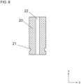
- the first ferrule 20 may include a recess 21 open on its outer periphery.
- the recess 21 may receive a retainer 50 described later.
- the recess 21 may have a rough surface.
- a rough surface refers to a surface having a greater surface roughness than other portions.
- the surface roughness may be measured and calculated by a stylus method as a contact method, or by a light interferometry method, a focus-variation image composition method, or a confocal method as a non-contact method.
- the measurement method may be selected as appropriate based on, for example, the size and the shape of a target object.
- the tube assembly 1 may include the retainer 50 that extends from the outer periphery of the first ferrule 20 to the living organism 60 and is connected to the living organism 60. More specifically, the retainer 50 fastens the living organism 60 and the first ferrule 20 together. This structure allows the tube assembly 1 to be firmly fixed to the living organism 60.
- the retainer 50 may be located at the recess 21. This structure increases the area of contact between the retainer 50 and the first ferrule 20 and improves the strength of connection between the living organism 60 and the first ferrule.
- the recess 21 including a rough surface further improves the strength of connection.
- the first ferrule 20 is made of a ceramic material. This reduces allergic reactions, such as metal allergy, in the living organism 60.
- the tube assembly 1 is thus less invasive to the living organism 60.
- the first ferrule 20 made of a ceramic material also facilitates measurement of the living organism 60 with, for example, MRI.
- the ceramic material used for the first ferrule 20 examples include Al 2 O 3 , ZrO 2 , AlN, SiC, Si 3 N 4 , 2MgO•SiO 2 , SiAlON, BaTiOs, PZT, ferrite, and mullite.
- the first ferrule 20 made of a zirconia ceramic material can have more accurate dimensions.
- the first ferrule 20 made of a zirconia ceramic material may include an additive.
- the additive may be, for example, a stabilizer such as Y 2 O 3 .
- the first ferrule 20 may thus be tougher.
- the entire outer peripheral surface of the first ferrule 20 may be rough.
- the first ferrule 20 may thus be held by tweezers more firmly and be less likely to be out of position in connecting to the living organism 60.
- the tube assembly 1 thus has high connection reliability.
- the first ferrule 20 illustrated in FIGs. 7 and 8 may be, for example, hollow cylindrical.
- its end in the positive z-direction may have a diameter of, for example, 1.0 to 5.0 mm
- its end in the negative z-direction may have a diameter of, for example, 1.0 to 5.0 mm.
- the size in z-direction may be 5 to 30 mm.
- the through-hole 22 may have a diameter of 0.5 to 3.0 mm.
- the retainer 50 may be made of a resin, such as an epoxy resin.
- the retainer 50 made of a resin may dry faster and thus be less damaging to the living organism 60.
- the tube assembly 1 is thus less invasive to the living organism 60.
- the tube assembly 1 may include the second ferrule 30 that fastens the outer periphery of the imaging fiber 70.
- This structure allows the imaging fiber 70 to be accurately connected to the first ferrule 20, as well as allowing the imaging fiber 70 to be less likely to break due to, for example, an impact.
- the imaging fiber 70 is placed in the through-hole 13 in the tube 10 to be fastened by the tube 10.
- the through-hole 31 in the second ferrule 30, the through-hole 13 in the tube 10, and the through-hole 22 in the first ferrule 20 are coaxial.
- the second ferrule 30 may be made of a ceramic material. This reduces allergic reactions, such as metal allergy, in the living organism 60.
- the first ferrule 20 made of a ceramic material allows more accurate connection to the second ferrule 30.
- the second ferrule 30 made of a ceramic material also facilitates measurement of the living organism 60 with, for example, MRI.
- the ceramic material used for the second ferrule 30 examples include Al 2 O 3 , ZrO 2 , AlN, SiC, Si 3 N 4 , 2MgO•SiO 2 , SiAlON, BaTiOs, PZT, ferrite, and mullite.
- the second ferrule 30 made of a zirconia ceramic material can have more accurate dimensions.
- the second ferrule 30 made of a zirconia ceramic material may include an additive.
- the additive may be, for example, a stabilizer such as Y 2 O 3 .
- the second ferrule 30 may thus be tougher.
- the entire outer peripheral surface of the second ferrule 30 may be rough.
- the second ferrule 30 may thus be held by tweezers more firmly and be less likely to be out of position in connecting to the living organism 60.
- the tube assembly 1 thus has high connection reliability.
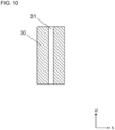
- the second ferrule 30 illustrated in FIGs. 9 and 10 may be, for example, hollow cylindrical.
- its end in the positive z-direction may have a diameter of, for example, 1.0 to 5.0 mm
- its end in the negative z-direction may have a diameter of, for example, 1.0 to 5.0 mm.
- the size in z-direction may be 5 to 30 mm.
- the through-hole 31 may have a diameter of 0.5 to 3.0 mm.
- the tube assembly 1 may include the sleeve 40 that fastens the outer peripheries of the first ferrule 20 and the second ferrule 30. With the sleeve 40 fastening the outer peripheries of the first ferrule 20 and the second ferrule 30, the through-hole 41 in the sleeve 40, the through-hole 13 in the tube 10, the through-hole 22 in the first ferrule 20, and the through-hole 31 in the second ferrule 30 are coaxial.
- the sleeve 40 may be made of a ceramic material. With the first ferrule 20 and the second ferrule 30 made of a ceramic material, the sleeve 40 can be accurately connected to the first ferrule 20 and the second ferrule 30.
- the sleeve 40 made of a ceramic material also facilitates measurement of the living organism 60 with, for example, MRI.
- the ceramic material used for the sleeve 40 examples include Al 2 O 3 , ZrO 2 , AlN, SiC, Si 3 N 4 , 2MgO•SiO 2 , SiAlON, BaTiOs, PZT, ferrite, and mullite.
- the sleeve 40 made of a zirconia ceramic material may have more accurate dimensions.
- the sleeve 40 made of a zirconia ceramic material may include an additive.
- the additive may be, for example, a stabilizer such as Y 2 O 3 .
- the sleeve 40 may thus be tougher.
- the sleeve 40 may be a split sleeve.
- the sleeve 40 may be a precision sleeve.
- the sleeve 40 is elastic and can fasten the first ferrule 20 and the second ferrule 30 firmly.
- the tube assembly 1 including the sleeve 40 has high connection reliability.
- a split sleeve includes a slit in z-direction as illustrated in FIG. 11 .
- a precision sleeve does not include a slit in z-direction unlike a split sleeve.
- the entire outer peripheral surface of the sleeve 40 may be rough.
- the sleeve 40 may thus be held by tweezers more firmly and be less likely to be out of position in connecting to the living organism 60.
- the tube assembly 1 thus has high connection reliability.
- the sleeve 40 illustrated in FIGs. 11 and 12 may be, for example, hollow cylindrical.
- its end in the positive z-direction may have a diameter of, for example, 1.5 to 8.0 mm
- its end in the negative z-direction may have a diameter of, for example, 1.5 to 8.0 mm.
- the size in z-direction may be 5 to 30 mm.
- the through-hole 41 may have a diameter of 1.0 to 5.0 mm.
- the dimensions of the components in the tube assembly 1 are not limited to the dimensions described above and may be any dimensions appropriate for, for example, the type of a measurement target and a target site to be measured.
- the imaging fiber 70 may be an optical fiber of, for example, quartz glass.
- the end face of the imaging fiber 70 may be connected to the lens 14.
- the measurement apparatus 100 for a living organism illustrated in FIG. 13 includes the tube assembly 1 described above and the imaging system 80 connected to the imaging fiber 70.
- the imaging system 80 may be, for example, an endoscopic system.
- the tube 10 and the first ferrule 20 in the tube assembly 1 may be formed through the processes described below. First, a powder of a ceramic material such as zirconia is kneaded with a thermoplastic binder into a mixture. The mixture is then molded under pressure into a molded body using a mold with a predetermined shape. The molded body is then fired at temperatures of about 1300 to 1600 °C. Through the above processes, the tube 10 and the first ferrule 20 of a ceramic material containing zirconia are formed. The second ferrule 30 and the sleeve 40 may also be formed by the above-described method used to form the tube 10 and the first ferrule 20.
- the mold used to form the first ferrule 20 includes a projection for forming the recess 21.
- the recess 21 may be formed.
- a mold for the tube 10 is processed to be tapered toward its distal end, and the mold is used to form the tube 10.
- abrasive blasting of propelling an abrasive material may be used.
- targeted portions to be roughened may be immersed in an etching solution to form rough surfaces through chemical erosion.
- the rough surfaces may be formed through a surface roughing process, in which a rough surface member made of, for example, a resin is pressed against the portions corresponding to the outer peripheries of the molded bodies to be the first ferrule 20, the second ferrule 30, and the sleeve 40, followed by firing.
- a tube assembly for a living organism includes a tube and a first ferrule.
- the tube is partially placeable into a living organism.
- the tube includes a first end, a second end, a through-hole, and a lens.
- the through-hole extends in a first direction from the second end to the first end.
- the first ferrule covers an outer periphery of the tube in the first direction.
- the lens is located in a portion of the through-hole including at least the first end.
- the tube and the first ferrule contain a ceramic material.
- the tube assembly for a living organism is less invasive to the living organism.
Landscapes
- Health & Medical Sciences (AREA)
- Life Sciences & Earth Sciences (AREA)
- Surgery (AREA)
- Optics & Photonics (AREA)
- Physics & Mathematics (AREA)
- Engineering & Computer Science (AREA)
- Biomedical Technology (AREA)
- General Health & Medical Sciences (AREA)
- Pathology (AREA)
- Nuclear Medicine, Radiotherapy & Molecular Imaging (AREA)
- Biophysics (AREA)
- Heart & Thoracic Surgery (AREA)
- Medical Informatics (AREA)
- Molecular Biology (AREA)
- Animal Behavior & Ethology (AREA)
- Radiology & Medical Imaging (AREA)
- Public Health (AREA)
- Veterinary Medicine (AREA)
- Mechanical Engineering (AREA)
- Manufacturing & Machinery (AREA)
- Endoscopes (AREA)
- Measurement Of The Respiration, Hearing Ability, Form, And Blood Characteristics Of Living Organisms (AREA)
- Mechanical Coupling Of Light Guides (AREA)
Abstract
Description
- The present disclosure relates to a tube assembly for a living organism and a measurement apparatus for a living organism.
- A known technique is described in, for example,
Patent Literature 1. -
- Patent Literature 1:
WO 2011/132756 - Patent Literature 2:
WO 2012/017950 - Patent Literature 3:
Japanese Unexamined Patent Application Publication (Translation of PCT Application) No. 2010-540202 - Patent Literature 4:
Japanese Patent No. 5224482 - In an embodiment according to the present disclosure, a tube assembly for a living organism includes a tube and a first ferrule. The tube is partially placeable into a living organism. The tube includes a first end, a second end, a through-hole, and a lens. The through-hole extends in a first direction from the second end to the first end. The first ferrule covers an outer periphery of the tube in the first direction. The lens is located in a portion of the through-hole including at least the first end. The tube and the first ferrule contain a ceramic material.
- The objects, features, and advantages of the present disclosure will become more apparent from the following detailed description and the drawings.
-
FIG. 1 is a plan view of a tube assembly for a living organism according to an embodiment of the present disclosure as viewed in y-direction. -
FIG. 2 is a developed plan view of the tube assembly for a living organism according to the embodiment of the present disclosure as viewed in y-direction. -
FIG. 3 is a perspective view of a tube in the tube assembly for a living organism illustrated inFIG. 2 . -
FIG. 4 is a sectional view of the tube illustrated inFIG. 3 taken in x-direction. -
FIG. 5 is an enlarged view of part V of the tube illustrated inFIG. 4 . -
FIG. 6 is a plan view of a tube assembly for a living organism according to another embodiment as viewed in y-direction. -
FIG. 7 is a plan view of a first ferrule in the tube assembly for a living organism illustrated inFIG. 2 as viewed in y-direction. -
FIG. 8 is a sectional view of the first ferrule illustrated inFIG. 7 taken in x-direction. -
FIG. 9 is a plan view of a second ferrule in the tube assembly for a living organism illustrated inFIG. 2 as viewed in y-direction. -
FIG. 10 is a sectional view of the second ferrule illustrated inFIG. 8 taken in x-direction. -
FIG. 11 is a perspective view of a sleeve in the tube assembly for a living organism illustrated inFIG. 2 . -
FIG. 12 is a sectional view of the sleeve illustrated inFIG. 11 taken in x-direction. -
FIG. 13 is a plan view of a measurement apparatus for a living organism according to an embodiment of the present disclosure as viewed in y-direction. - A tube assembly for a living organism and a measurement apparatus for a living organism are used to, for example, record information on neural activity over a predetermined period from the brains of small animals including rodents, such as mice or rats, and marmosets. The structure that forms the basis of a tube assembly for a living organism and a measurement apparatus for a living organism according to one or more embodiments of the present disclosure includes, for example, an elongated object such as a wire electrode implanted and fixed in the brain of a small animal. Example methods used to fix such a wire electrode in a living organism include directly implanting and fixing a linear wire electrode of, for example, relatively rigid stainless steel or stainless alloy in the living organism, or using guide members, for example, screws, to fasten the wire electrode.
- A
tube assembly 1 for a living organism and ameasurement apparatus 100 for a living organism according to one or more embodiments of the present disclosure will now be described with reference to the drawings. The orthogonal xyz coordinate system may be used herein for ease of explanation. Structure ofTube Assembly 1 for Living Organism - In one or more embodiments of the present disclosure, the
tube assembly 1 for a living organism (hereafter referred to as the tube assembly 1) is used to obtain information on, for example, neural activity from the brain of aliving organism 60, for example, a small experimental animal such as a rodent or a marmoset, or an experimental primate such as a monkey or a chimpanzee. Thetube assembly 1 is also used to obtain information on cell activity in, for example, an organ or information on the blood flow in a blood vessel. Thetube assembly 1 is also used for medical care, for example, treating people or animals. - In one or more embodiments of the present disclosure, the
tube assembly 1 includes atube 10 and afirst ferrule 20. As illustrated inFIG. 1 , thetube assembly 1 may include thetube 10, thefirst ferrule 20, asecond ferrule 30, and asleeve 40. As illustrated inFIG. 2 , thetube 10 is partially placed in theliving organism 60. Thetube 10 includes afirst end 11, asecond end 12, a through-hole 13, and alens 14. The through-hole 13 extends in a first direction from thesecond end 12 to thefirst end 11. Thelens 14 is located in a portion of the through-hole 13 including at least thefirst end 11. Thefirst ferrule 20 covers the outer periphery of thetube 10 in the first direction. The first direction herein is from thesecond end 12 to thefirst end 11. The through-hole 13 in thetube 10 receives animaging fiber 70 placed in the first direction. - The
tube assembly 1 including, as illustrated inFIG. 1 , thetube 10, thefirst ferrule 20, thesecond ferrule 30, and thesleeve 40 is connected to theliving organism 60 as described below. First, thetube 10 including thefirst ferrule 20 on its outer periphery is fixed with thefirst end 11 placed through, for example, an organ, the scalp, or the skull of theliving organism 60. Theliving organism 60 that is a small experimental animal or an experimental primate may be kept with thefirst ferrule 20 and thetube 10 fixed to theliving organism 60. To conduct an experiment for obtaining information on, for example, neural activity or to perform treatment, theimaging fiber 70 connected to the through-hole 31 in thesecond ferrule 30, or in other words, located in the through-hole 31, is placed in the through-hole 13 in thetube 10. The outer peripheries of thefirst ferrule 20 and thesecond ferrule 30 are fastened by thesleeve 40. Light through thelens 14 in thetube 10 travels through theimaging fiber 70 connected to animaging system 80 described later. Theimaging system 80 processes the optical information and measures, for example, neural activity in theliving organism 60. With thefirst ferrule 20 and thetube 10 constantly fixed to theliving organism 60, theliving organism 60 does not undergo repeated insertion and removal of an object for every experiment. Thetube assembly 1 is thus less invasive to theliving organism 60. This structure also allows measurement of the same part of theliving organism 60 and increases the reliability of the measurement results. To fix thetube assembly 1 to theliving organism 60, an operator uses tweezers to hold thetube assembly 1 and attaches thetube assembly 1 to a target site to be measured, for example, an organ, the scalp, or the skull. - As illustrated in
FIG. 1 , thefirst end 11 of thetube 10 may protrude from thefirst ferrule 20. This facilitates placement of thetube 10 in theliving organism 60. Thetube assembly 1 is thus easily operable. - As illustrated in
FIG. 6 , thetube 10 has an outer diameter that may be gradually smaller toward thefirst end 11. This allows thetube 10 to be placed in the livingorganism 60 more easily. Additionally, the livingorganism 60 suffers less damage during the insertion. Thetube assembly 1 is thus less invasive to the livingorganism 60. - The
tube 10 is made of a ceramic material. This reduces allergic reactions, such as metal allergy, in the livingorganism 60 compared with when, for example, thetube 10 is made of metal. Thetube assembly 1 is thus less invasive to the livingorganism 60. Thetube 10 made of a ceramic material also facilitates measurement of the livingorganism 60 with, for example, magnetic resonance imaging (MRI). - Examples of the ceramic material used for the
tube 10 include alumina (Al2O3), zirconia (ZrO2), aluminum nitride (AlN), silicon carbide (SiC), silicon nitride (Si3N4), forsterite (2MgO•SiO2), sialon (SiAlON), barium titanate (BaTiO3), lead zirconate titanate (PZT), ferrite, and mullite. For thetube 10 made of a zirconia ceramic material, fine particles of zirconia allow thetube 10 to have more accurate dimensions. In some embodiments, thetube 10 made of a zirconia ceramic material may include an additive. The additive may be, for example, a stabilizer such as yttria (Y2O3). Thetube 10 may thus be tougher. - As illustrated in
FIG. 3 , thetube 10 may be, for example, hollow cylindrical. For thetube 10 that is hollow cylindrical, thefirst end 11 and thesecond end 12 may each have a diameter of, for example, 0.5 to 3.0 mm. The size in z-direction may be 5 to 30 mm. The through-hole 13 may have a diameter of 0.3 to 2.0 mm. - The
lens 14 is located in the through-hole 13 in thetube 10 and may have the same shape as the through-hole 13 in thetube 10. More specifically, thelens 14 may be solid cylindrical. For thelens 14 that is solid cylindrical, its end in the positive z-direction may have a diameter of, for example, 0.3 to 2.0 mm, and its end in the negative z-direction may have a diameter of, for example, 0.3 to 2.0 mm. The size in z-direction may be 0.3 to 3.0 mm. - The
lens 14 may be, for example, a rod lens or a GRIN lens. - As illustrated in
FIG. 5 , which is an enlarged view ofFIG. 4 , thelens 14 may protrude from thefirst end 11. This structure allows thelens 14 to come in contact with a site to be measured in the livingorganism 60 and improves the accuracy of data collection. Thetube assembly 1 including thelens 14 has high measurement accuracy. - For the
tube assembly 1 including thefirst ferrule 20, thefirst ferrule 20 functions as a stopper when thefirst end 11 is placed through, for example, the scalp and the skull of the head of a small experimental animal. With thefirst ferrule 20 functioning as a stopper, thetube assembly 1 is more easily fixed and is less likely to be placed deeper in the livingorganism 60 than an appropriate depth when thetube assembly 1 is connected to the livingorganism 60. Thetube assembly 1 is thus more stably connected and is less invasive to the livingorganism 60. Thefirst ferrule 20 fastens the outer periphery of thetube 10, and the through-hole 13 in thetube 10 and the through-hole 22 in thefirst ferrule 20 are coaxial. - The
first ferrule 20 may include arecess 21 open on its outer periphery. Therecess 21 may receive aretainer 50 described later. Therecess 21 may have a rough surface. A rough surface refers to a surface having a greater surface roughness than other portions. The surface roughness may be measured and calculated by a stylus method as a contact method, or by a light interferometry method, a focus-variation image composition method, or a confocal method as a non-contact method. The measurement method may be selected as appropriate based on, for example, the size and the shape of a target object. - As illustrated in
FIG. 2 , thetube assembly 1 may include theretainer 50 that extends from the outer periphery of thefirst ferrule 20 to the livingorganism 60 and is connected to the livingorganism 60. More specifically, theretainer 50 fastens the livingorganism 60 and thefirst ferrule 20 together. This structure allows thetube assembly 1 to be firmly fixed to the livingorganism 60. - When the
first ferrule 20 includes therecess 21, theretainer 50 may be located at therecess 21. This structure increases the area of contact between theretainer 50 and thefirst ferrule 20 and improves the strength of connection between the livingorganism 60 and the first ferrule. Therecess 21 including a rough surface further improves the strength of connection. - The
first ferrule 20 is made of a ceramic material. This reduces allergic reactions, such as metal allergy, in the livingorganism 60. Thetube assembly 1 is thus less invasive to the livingorganism 60. Thefirst ferrule 20 made of a ceramic material also facilitates measurement of the livingorganism 60 with, for example, MRI. - Examples of the ceramic material used for the
first ferrule 20 include Al2O3, ZrO2, AlN, SiC, Si3N4, 2MgO•SiO2, SiAlON, BaTiOs, PZT, ferrite, and mullite. Thefirst ferrule 20 made of a zirconia ceramic material can have more accurate dimensions. In some embodiments, thefirst ferrule 20 made of a zirconia ceramic material may include an additive. The additive may be, for example, a stabilizer such as Y2O3. Thefirst ferrule 20 may thus be tougher. - The entire outer peripheral surface of the
first ferrule 20 may be rough. Thefirst ferrule 20 may thus be held by tweezers more firmly and be less likely to be out of position in connecting to the livingorganism 60. Thetube assembly 1 thus has high connection reliability. - The
first ferrule 20 illustrated inFIGs. 7 and8 may be, for example, hollow cylindrical. For thefirst ferrule 20 that is hollow cylindrical, its end in the positive z-direction may have a diameter of, for example, 1.0 to 5.0 mm, and its end in the negative z-direction may have a diameter of, for example, 1.0 to 5.0 mm. The size in z-direction may be 5 to 30 mm. The through-hole 22 may have a diameter of 0.5 to 3.0 mm. - The
retainer 50 may be made of a resin, such as an epoxy resin. Theretainer 50 made of a resin may dry faster and thus be less damaging to the livingorganism 60. Thetube assembly 1 is thus less invasive to the livingorganism 60. - The
tube assembly 1 may include thesecond ferrule 30 that fastens the outer periphery of theimaging fiber 70. This structure allows theimaging fiber 70 to be accurately connected to thefirst ferrule 20, as well as allowing theimaging fiber 70 to be less likely to break due to, for example, an impact. Theimaging fiber 70 is placed in the through-hole 13 in thetube 10 to be fastened by thetube 10. In this structure, the through-hole 31 in thesecond ferrule 30, the through-hole 13 in thetube 10, and the through-hole 22 in thefirst ferrule 20 are coaxial. - The
second ferrule 30 may be made of a ceramic material. This reduces allergic reactions, such as metal allergy, in the livingorganism 60. Thefirst ferrule 20 made of a ceramic material allows more accurate connection to thesecond ferrule 30. Thesecond ferrule 30 made of a ceramic material also facilitates measurement of the livingorganism 60 with, for example, MRI. - Examples of the ceramic material used for the
second ferrule 30 include Al2O3, ZrO2, AlN, SiC, Si3N4, 2MgO•SiO2, SiAlON, BaTiOs, PZT, ferrite, and mullite. Thesecond ferrule 30 made of a zirconia ceramic material can have more accurate dimensions. In some embodiments, thesecond ferrule 30 made of a zirconia ceramic material may include an additive. The additive may be, for example, a stabilizer such as Y2O3. Thesecond ferrule 30 may thus be tougher. - The entire outer peripheral surface of the
second ferrule 30 may be rough. Thesecond ferrule 30 may thus be held by tweezers more firmly and be less likely to be out of position in connecting to the livingorganism 60. Thetube assembly 1 thus has high connection reliability. - The
second ferrule 30 illustrated inFIGs. 9 and10 may be, for example, hollow cylindrical. For thesecond ferrule 30 that is hollow cylindrical, its end in the positive z-direction may have a diameter of, for example, 1.0 to 5.0 mm, and its end in the negative z-direction may have a diameter of, for example, 1.0 to 5.0 mm. The size in z-direction may be 5 to 30 mm. The through-hole 31 may have a diameter of 0.5 to 3.0 mm. - The
tube assembly 1 may include thesleeve 40 that fastens the outer peripheries of thefirst ferrule 20 and thesecond ferrule 30. With thesleeve 40 fastening the outer peripheries of thefirst ferrule 20 and thesecond ferrule 30, the through-hole 41 in thesleeve 40, the through-hole 13 in thetube 10, the through-hole 22 in thefirst ferrule 20, and the through-hole 31 in thesecond ferrule 30 are coaxial. - The
sleeve 40 may be made of a ceramic material. With thefirst ferrule 20 and thesecond ferrule 30 made of a ceramic material, thesleeve 40 can be accurately connected to thefirst ferrule 20 and thesecond ferrule 30. Thesleeve 40 made of a ceramic material also facilitates measurement of the livingorganism 60 with, for example, MRI. - Examples of the ceramic material used for the
sleeve 40 include Al2O3, ZrO2, AlN, SiC, Si3N4, 2MgO•SiO2, SiAlON, BaTiOs, PZT, ferrite, and mullite. Thesleeve 40 made of a zirconia ceramic material may have more accurate dimensions. In some embodiments, thesleeve 40 made of a zirconia ceramic material may include an additive. The additive may be, for example, a stabilizer such as Y2O3. Thesleeve 40 may thus be tougher. - The
sleeve 40 may be a split sleeve. In some embodiments, thesleeve 40 may be a precision sleeve. For thesleeve 40 being a split sleeve, thesleeve 40 is elastic and can fasten thefirst ferrule 20 and thesecond ferrule 30 firmly. Thetube assembly 1 including thesleeve 40 has high connection reliability. A split sleeve includes a slit in z-direction as illustrated inFIG. 11 . A precision sleeve does not include a slit in z-direction unlike a split sleeve. - The entire outer peripheral surface of the
sleeve 40 may be rough. Thesleeve 40 may thus be held by tweezers more firmly and be less likely to be out of position in connecting to the livingorganism 60. Thetube assembly 1 thus has high connection reliability. - The
sleeve 40 illustrated inFIGs. 11 and12 may be, for example, hollow cylindrical. For thesleeve 40 that is hollow cylindrical, its end in the positive z-direction may have a diameter of, for example, 1.5 to 8.0 mm, and its end in the negative z-direction may have a diameter of, for example, 1.5 to 8.0 mm. The size in z-direction may be 5 to 30 mm. The through-hole 41 may have a diameter of 1.0 to 5.0 mm. - The dimensions of the components in the
tube assembly 1 are not limited to the dimensions described above and may be any dimensions appropriate for, for example, the type of a measurement target and a target site to be measured. - The
imaging fiber 70 may be an optical fiber of, for example, quartz glass. - When the
imaging fiber 70 is placed in the through-hole 13 in thetube 10, the end face of theimaging fiber 70 may be connected to thelens 14. - The
measurement apparatus 100 for a living organism illustrated inFIG. 13 includes thetube assembly 1 described above and theimaging system 80 connected to theimaging fiber 70. - The
imaging system 80 may be, for example, an endoscopic system. - The
tube 10 and thefirst ferrule 20 in thetube assembly 1 may be formed through the processes described below. First, a powder of a ceramic material such as zirconia is kneaded with a thermoplastic binder into a mixture. The mixture is then molded under pressure into a molded body using a mold with a predetermined shape. The molded body is then fired at temperatures of about 1300 to 1600 °C. Through the above processes, thetube 10 and thefirst ferrule 20 of a ceramic material containing zirconia are formed. Thesecond ferrule 30 and thesleeve 40 may also be formed by the above-described method used to form thetube 10 and thefirst ferrule 20. - When the
first ferrule 20 includes therecess 21 as illustrated inFIG. 7 , the mold used to form thefirst ferrule 20 includes a projection for forming therecess 21. Thus, therecess 21 may be formed. To form atube 10 including a distal end tapered toward thefirst end 11, a mold for thetube 10 is processed to be tapered toward its distal end, and the mold is used to form thetube 10. - To create rough surfaces on the outer peripheries of the
recess 21 on thefirst ferrule 20, thefirst ferrule 20, thesecond ferrule 30, and thesleeve 40, abrasive blasting of propelling an abrasive material may be used. In some embodiments, targeted portions to be roughened may be immersed in an etching solution to form rough surfaces through chemical erosion. In other embodiments, the rough surfaces may be formed through a surface roughing process, in which a rough surface member made of, for example, a resin is pressed against the portions corresponding to the outer peripheries of the molded bodies to be thefirst ferrule 20, thesecond ferrule 30, and thesleeve 40, followed by firing. - The present disclosure may be implemented in the following forms.
- In an embodiment according to the present disclosure, a tube assembly for a living organism includes a tube and a first ferrule. The tube is partially placeable into a living organism. The tube includes a first end, a second end, a through-hole, and a lens. The through-hole extends in a first direction from the second end to the first end. The first ferrule covers an outer periphery of the tube in the first direction. The lens is located in a portion of the through-hole including at least the first end. The tube and the first ferrule contain a ceramic material.
- In an embodiment of the present disclosure, the tube assembly for a living organism is less invasive to the living organism.
- The present disclosure is not limited to the embodiments described above. Numerical values and other features may also be varied for the components. Various combinations of the embodiments according to the present disclosure is not limited to the examples described in the above embodiments.
-
- 1
- tube assembly for living organism
- 10
- tube
- 11
- first end
- 12
- second end
- 13
- through-hole
- 14
- lens
- 20
- first ferrule
- 21
- recess
- 22
- through-hole
- 30
- second ferrule
- 31
- through-hole
- 40
- sleeve
- 50
- retainer
- 60
- living organism
- 70
- imaging fiber
- 80
- imaging system
- 100
- measurement apparatus for living organism
Claims (12)
- A tube assembly for a living organism, the tube assembly comprising:a tube partially placeable into a living organism, the tube including a first end, a second end, and a through-hole extending in a first direction from the second end to the first end; anda first ferrule covering an outer periphery of the tube in the first direction,wherein the tube includes a lens in a portion of the through-hole including at least the first end, andthe tube and the first ferrule comprise a ceramic material.
- The tube assembly according to claim 1, wherein
the first end protrudes from the first ferrule. - The tube assembly according to claim 1 or claim 2, wherein
the tube has an outer diameter gradually smaller toward the first end. - The tube assembly according to any one of claims 1 to 3, wherein
the lens protrudes from the first end. - The tube assembly according to any one of claims 1 to 4, further comprising:
a retainer extending from an outer periphery of the first ferrule and to be connected to the living organism. - The tube assembly according to claim 5, wherein
the first ferrule includes a recess being open on the outer periphery of the first ferrule, and the retainer is located at the recess. - The tube assembly according to claim 5 or claim 6, wherein
the retainer comprises a resin. - The tube assembly according to any one of claims 1 to 7, wherein
the tube comprises a zirconia ceramic material. - The tube assembly according to any one of claims 1 to 8, further comprising:
an imaging fiber connectable to the lens located in the through-hole. - The tube assembly according to claim 9, further comprising:a second ferrule configured to fasten an outer periphery of the imaging fiber, the second ferrule comprising a ceramic material; anda sleeve configured to fasten outer peripheries of the first ferrule and the second ferrule, the sleeve comprising a ceramic material.
- The tube assembly according to claim 10, wherein
the sleeve is a split sleeve. - A measurement apparatus for a living organism, the measurement apparatus comprising:the tube assembly according to any one of claims 9 to 11; andan imaging system connectable to the imaging fiber.
Applications Claiming Priority (2)
| Application Number | Priority Date | Filing Date | Title |
|---|---|---|---|
| JP2020086095 | 2020-05-15 | ||
| PCT/JP2021/018508 WO2021230377A1 (en) | 2020-05-15 | 2021-05-14 | Biomedical tube and biometric device |
Publications (3)
| Publication Number | Publication Date |
|---|---|
| EP4151158A1 true EP4151158A1 (en) | 2023-03-22 |
| EP4151158A4 EP4151158A4 (en) | 2024-05-29 |
| EP4151158B1 EP4151158B1 (en) | 2026-01-21 |
Family
ID=78525191
Family Applications (1)
| Application Number | Title | Priority Date | Filing Date |
|---|---|---|---|
| EP21802951.0A Active EP4151158B1 (en) | 2020-05-15 | 2021-05-14 | Biomedical tube and biometric device |
Country Status (5)
| Country | Link |
|---|---|
| US (1) | US20230181009A1 (en) |
| EP (1) | EP4151158B1 (en) |
| JP (1) | JP7489072B2 (en) |
| CN (1) | CN115551418A (en) |
| WO (1) | WO2021230377A1 (en) |
Family Cites Families (20)
| Publication number | Priority date | Publication date | Assignee | Title |
|---|---|---|---|---|
| US6749344B2 (en) * | 2001-10-24 | 2004-06-15 | Scimed Life Systems, Inc. | Connection apparatus for optical coherence tomography catheters |
| US8346346B1 (en) | 2005-01-24 | 2013-01-01 | The Board Of Trustees Of The Leland Stanford Junior University | Optical analysis system and approach therefor |
| US7837683B2 (en) * | 2005-05-13 | 2010-11-23 | Electrosurgery Associates, Llc | Electrosurgical ablation electrode with aspiration and method for using same |
| EP2211973A2 (en) * | 2007-10-08 | 2010-08-04 | Renishaw (Ireland) Limited | Catheter |
| US8874201B2 (en) | 2008-09-30 | 2014-10-28 | National University Corporation NARA Institute of Science and Technology | Intracerebral information measuring device |
| JP5750440B2 (en) * | 2009-07-29 | 2015-07-22 | マウナ ケア テクノロジーズ | Apparatus and method for brain fiber bundle microscopy |
| EP2561806B1 (en) | 2010-04-21 | 2019-06-12 | Tohoku University | Electroencephalogram electrode unit for small animals and measurement system using same |
| WO2012017950A1 (en) | 2010-08-03 | 2012-02-09 | 学校法人 久留米大学 | Electroencephalographic electrode device for small laboratory animal and electroencephalographic method |
| WO2012124092A1 (en) * | 2011-03-16 | 2012-09-20 | 東洋ガラス株式会社 | Microimaging probe and manufacturing method thereof |
| JP2012239669A (en) * | 2011-05-20 | 2012-12-10 | Konica Minolta Advanced Layers Inc | Probe and diagnostic system |
| CN203662756U (en) * | 2014-01-09 | 2014-06-25 | 杨丽红 | Electrocardiogram lead electrode for animal experiment |
| US9810854B2 (en) * | 2014-01-20 | 2017-11-07 | Kyocera Corporation | Optical fiber holding component, receptacle-equipped pigtail, patch cord, and optical module |
| WO2016167204A1 (en) * | 2015-04-16 | 2016-10-20 | 住友電気工業株式会社 | Optical probe |
| WO2017087542A1 (en) | 2015-11-18 | 2017-05-26 | The Board Of Trustees Of The Leland Stanford Junior University | Method and systems for measuring neural activity |
| WO2017163675A1 (en) * | 2016-03-23 | 2017-09-28 | オリンパス株式会社 | Endoscope and endoscope system |
| JPWO2017170662A1 (en) * | 2016-03-31 | 2019-02-07 | 国立大学法人東北大学 | Optical imaging device |
| US10314491B2 (en) * | 2017-02-11 | 2019-06-11 | The General Hospital Corporation | Optics for apodizing an optical imaging probe beam |
| US11160621B2 (en) * | 2017-11-17 | 2021-11-02 | Intuitive Surgical Operations, Inc. | Surgical instrument sterile adapter with optical coupler |
| GB2569177B (en) * | 2017-12-08 | 2019-12-04 | Surgerytech Aps | Endoscope system |
| JPWO2020045669A1 (en) * | 2018-08-31 | 2021-08-26 | 京セラ株式会社 | Ferrules for optical connectors, optical connectors and composite fiber connection structures |
-
2021
- 2021-05-14 EP EP21802951.0A patent/EP4151158B1/en active Active
- 2021-05-14 WO PCT/JP2021/018508 patent/WO2021230377A1/en not_active Ceased
- 2021-05-14 JP JP2022522226A patent/JP7489072B2/en active Active
- 2021-05-14 CN CN202180034801.8A patent/CN115551418A/en active Pending
- 2021-05-14 US US17/925,123 patent/US20230181009A1/en active Pending
Also Published As
| Publication number | Publication date |
|---|---|
| CN115551418A (en) | 2022-12-30 |
| EP4151158A4 (en) | 2024-05-29 |
| JP7489072B2 (en) | 2024-05-23 |
| JPWO2021230377A1 (en) | 2021-11-18 |
| US20230181009A1 (en) | 2023-06-15 |
| EP4151158B1 (en) | 2026-01-21 |
| WO2021230377A1 (en) | 2021-11-18 |
Similar Documents
| Publication | Publication Date | Title |
|---|---|---|
| Hanson et al. | The “sewing machine” for minimally invasive neural recording | |
| Wang et al. | A parylene neural probe array for multi-region deep brain recordings | |
| Welkenhuysen et al. | Effect of insertion speed on tissue response and insertion mechanics of a chronically implanted silicon-based neural probe | |
| Patel et al. | Utah array characterization and histological analysis of a multi-year implant in non-human primate motor and sensory cortices | |
| US7393629B2 (en) | Method and devices for transferring biological cells between a carrier and a probe | |
| Dangi et al. | Towards a low-cost and portable photoacoustic microscope for point-of-care and wearable applications | |
| US11944456B2 (en) | Ceramic guide, ceramic guide device, and cermic guide module | |
| DE69817368D1 (en) | DEVICE FOR GUIDING PERCUTANEOUS DEVICES BY COMPUTER-TOMOGRAPH | |
| EP4151158B1 (en) | Biomedical tube and biometric device | |
| Obaid et al. | Ultra-sensitive measurement of brain penetration with microscale probes for brain machine interface considerations | |
| KR101689769B1 (en) | The multi-channel metal microneedle array electrode for biosignal measurement and the manufacturing method thereof | |
| US20210338127A1 (en) | Apparatus and method for inserting electrode-based probes into biological tissue | |
| WO2012124092A1 (en) | Microimaging probe and manufacturing method thereof | |
| Pothof et al. | Fabrication and characterization of a high-resolution neural probe for stereoelectroencephalography and single neuron recording | |
| RU2653815C1 (en) | Method of implanting optic fiber probe in animal brain to generate controlled feedback | |
| EP3263039A1 (en) | Ultrasonic probe | |
| CN115500835B (en) | A flexible neural probe implant structure, preparation method and implantation device | |
| US11675141B2 (en) | Optical connector ferrule, optical connector, and composite fiber connecting assembly | |
| KR100731169B1 (en) | Micro spikes made of bioelastic superelastic alloys and their fabrication methods | |
| WO2020152628A2 (en) | Tissue access device | |
| Jacobs et al. | Standard Operating Protocol: Implantation of Cambrige NeuroTech chronic silicon probe and mini-amp-64 digital headstage in mice | |
| CN223287147U (en) | A cannula for multiphoton fluorescence microscopy in vivo brain imaging | |
| Liu et al. | Single-fiber OCT/FBG coaxial sensor for simultaneous ranging and force sensing | |
| Hwang et al. | A preliminary study on the method for stable and reliable implantation of neural interfaces into peripheral nervous system | |
| CN105682704B (en) | needle manufacturing method |
Legal Events
| Date | Code | Title | Description |
|---|---|---|---|
| STAA | Information on the status of an ep patent application or granted ep patent |
Free format text: STATUS: THE INTERNATIONAL PUBLICATION HAS BEEN MADE |
|
| PUAI | Public reference made under article 153(3) epc to a published international application that has entered the european phase |
Free format text: ORIGINAL CODE: 0009012 |
|
| STAA | Information on the status of an ep patent application or granted ep patent |
Free format text: STATUS: REQUEST FOR EXAMINATION WAS MADE |
|
| 17P | Request for examination filed |
Effective date: 20221111 |
|
| AK | Designated contracting states |
Kind code of ref document: A1 Designated state(s): AL AT BE BG CH CY CZ DE DK EE ES FI FR GB GR HR HU IE IS IT LI LT LU LV MC MK MT NL NO PL PT RO RS SE SI SK SM TR |
|
| P01 | Opt-out of the competence of the unified patent court (upc) registered |
Effective date: 20230505 |
|
| DAV | Request for validation of the european patent (deleted) | ||
| DAX | Request for extension of the european patent (deleted) | ||
| A4 | Supplementary search report drawn up and despatched |
Effective date: 20240502 |
|
| RIC1 | Information provided on ipc code assigned before grant |
Ipc: A61B 1/00 20060101ALI20240426BHEP Ipc: A61B 10/00 20060101AFI20240426BHEP |
|
| GRAP | Despatch of communication of intention to grant a patent |
Free format text: ORIGINAL CODE: EPIDOSNIGR1 |
|
| STAA | Information on the status of an ep patent application or granted ep patent |
Free format text: STATUS: GRANT OF PATENT IS INTENDED |
|
| INTG | Intention to grant announced |
Effective date: 20250326 |
|
| GRAJ | Information related to disapproval of communication of intention to grant by the applicant or resumption of examination proceedings by the epo deleted |
Free format text: ORIGINAL CODE: EPIDOSDIGR1 |
|
| STAA | Information on the status of an ep patent application or granted ep patent |
Free format text: STATUS: REQUEST FOR EXAMINATION WAS MADE |
|
| GRAP | Despatch of communication of intention to grant a patent |
Free format text: ORIGINAL CODE: EPIDOSNIGR1 |
|
| STAA | Information on the status of an ep patent application or granted ep patent |
Free format text: STATUS: GRANT OF PATENT IS INTENDED |
|
| INTC | Intention to grant announced (deleted) | ||
| INTG | Intention to grant announced |
Effective date: 20250806 |
|
| GRAS | Grant fee paid |
Free format text: ORIGINAL CODE: EPIDOSNIGR3 |
|
| GRAA | (expected) grant |
Free format text: ORIGINAL CODE: 0009210 |
|
| STAA | Information on the status of an ep patent application or granted ep patent |
Free format text: STATUS: THE PATENT HAS BEEN GRANTED |
|
| AK | Designated contracting states |
Kind code of ref document: B1 Designated state(s): AL AT BE BG CH CY CZ DE DK EE ES FI FR GB GR HR HU IE IS IT LI LT LU LV MC MK MT NL NO PL PT RO RS SE SI SK SM TR |
|
| REG | Reference to a national code |
Ref country code: CH Ref legal event code: F10 Free format text: ST27 STATUS EVENT CODE: U-0-0-F10-F00 (AS PROVIDED BY THE NATIONAL OFFICE) Effective date: 20260121 |
|
| REG | Reference to a national code |
Ref country code: DE Ref legal event code: R096 Ref document number: 602021046440 Country of ref document: DE |
|
| REG | Reference to a national code |
Ref country code: IE Ref legal event code: FG4D |
|
| REG | Reference to a national code |
Ref country code: NL Ref legal event code: MP Effective date: 20260121 |
|
| PG25 | Lapsed in a contracting state [announced via postgrant information from national office to epo] |
Ref country code: NL Free format text: LAPSE BECAUSE OF FAILURE TO SUBMIT A TRANSLATION OF THE DESCRIPTION OR TO PAY THE FEE WITHIN THE PRESCRIBED TIME-LIMIT Effective date: 20260121 |
|
| REG | Reference to a national code |
Ref country code: AT Ref legal event code: MK05 Ref document number: 1878153 Country of ref document: AT Kind code of ref document: T Effective date: 20260121 |
|
| PG25 | Lapsed in a contracting state [announced via postgrant information from national office to epo] |
Ref country code: RS Free format text: LAPSE BECAUSE OF FAILURE TO SUBMIT A TRANSLATION OF THE DESCRIPTION OR TO PAY THE FEE WITHIN THE PRESCRIBED TIME-LIMIT Effective date: 20260421 |
|
| PG25 | Lapsed in a contracting state [announced via postgrant information from national office to epo] |
Ref country code: ES Free format text: LAPSE BECAUSE OF FAILURE TO SUBMIT A TRANSLATION OF THE DESCRIPTION OR TO PAY THE FEE WITHIN THE PRESCRIBED TIME-LIMIT Effective date: 20260121 |
|
| PG25 | Lapsed in a contracting state [announced via postgrant information from national office to epo] |
Ref country code: PL Free format text: LAPSE BECAUSE OF FAILURE TO SUBMIT A TRANSLATION OF THE DESCRIPTION OR TO PAY THE FEE WITHIN THE PRESCRIBED TIME-LIMIT Effective date: 20260121 |
|
| PG25 | Lapsed in a contracting state [announced via postgrant information from national office to epo] |
Ref country code: GR Free format text: LAPSE BECAUSE OF FAILURE TO SUBMIT A TRANSLATION OF THE DESCRIPTION OR TO PAY THE FEE WITHIN THE PRESCRIBED TIME-LIMIT Effective date: 20260422 |
|
| REG | Reference to a national code |
Ref country code: LT Ref legal event code: MG9D |
|
| PG25 | Lapsed in a contracting state [announced via postgrant information from national office to epo] |
Ref country code: LT Free format text: LAPSE BECAUSE OF FAILURE TO SUBMIT A TRANSLATION OF THE DESCRIPTION OR TO PAY THE FEE WITHIN THE PRESCRIBED TIME-LIMIT Effective date: 20260121 |
|
| PGFP | Annual fee paid to national office [announced via postgrant information from national office to epo] |
Ref country code: DE Payment date: 20260413 Year of fee payment: 6 |
|
| PG25 | Lapsed in a contracting state [announced via postgrant information from national office to epo] |
Ref country code: NO Free format text: LAPSE BECAUSE OF FAILURE TO SUBMIT A TRANSLATION OF THE DESCRIPTION OR TO PAY THE FEE WITHIN THE PRESCRIBED TIME-LIMIT Effective date: 20260421 |
|
| PG25 | Lapsed in a contracting state [announced via postgrant information from national office to epo] |
Ref country code: AT Free format text: LAPSE BECAUSE OF FAILURE TO SUBMIT A TRANSLATION OF THE DESCRIPTION OR TO PAY THE FEE WITHIN THE PRESCRIBED TIME-LIMIT Effective date: 20260121 Ref country code: SE Free format text: LAPSE BECAUSE OF FAILURE TO SUBMIT A TRANSLATION OF THE DESCRIPTION OR TO PAY THE FEE WITHIN THE PRESCRIBED TIME-LIMIT Effective date: 20260121 Ref country code: FI Free format text: LAPSE BECAUSE OF FAILURE TO SUBMIT A TRANSLATION OF THE DESCRIPTION OR TO PAY THE FEE WITHIN THE PRESCRIBED TIME-LIMIT Effective date: 20260121 |
|
| PG25 | Lapsed in a contracting state [announced via postgrant information from national office to epo] |
Ref country code: HR Free format text: LAPSE BECAUSE OF FAILURE TO SUBMIT A TRANSLATION OF THE DESCRIPTION OR TO PAY THE FEE WITHIN THE PRESCRIBED TIME-LIMIT Effective date: 20260121 |
|
| PG25 | Lapsed in a contracting state [announced via postgrant information from national office to epo] |
Ref country code: PT Free format text: LAPSE BECAUSE OF FAILURE TO SUBMIT A TRANSLATION OF THE DESCRIPTION OR TO PAY THE FEE WITHIN THE PRESCRIBED TIME-LIMIT Effective date: 20260521 Ref country code: IS Free format text: LAPSE BECAUSE OF FAILURE TO SUBMIT A TRANSLATION OF THE DESCRIPTION OR TO PAY THE FEE WITHIN THE PRESCRIBED TIME-LIMIT Effective date: 20260521 |
|
| PG25 | Lapsed in a contracting state [announced via postgrant information from national office to epo] |
Ref country code: LV Free format text: LAPSE BECAUSE OF FAILURE TO SUBMIT A TRANSLATION OF THE DESCRIPTION OR TO PAY THE FEE WITHIN THE PRESCRIBED TIME-LIMIT Effective date: 20260121 |
|
| PG25 | Lapsed in a contracting state [announced via postgrant information from national office to epo] |
Ref country code: BG Free format text: LAPSE BECAUSE OF FAILURE TO SUBMIT A TRANSLATION OF THE DESCRIPTION OR TO PAY THE FEE WITHIN THE PRESCRIBED TIME-LIMIT Effective date: 20260121 |