EP4150779B1 - Antennenstrahlvirtualisierung für drahtlose breitstrahlkommunikation - Google Patents
Antennenstrahlvirtualisierung für drahtlose breitstrahlkommunikation Download PDFInfo
- Publication number
- EP4150779B1 EP4150779B1 EP20726345.0A EP20726345A EP4150779B1 EP 4150779 B1 EP4150779 B1 EP 4150779B1 EP 20726345 A EP20726345 A EP 20726345A EP 4150779 B1 EP4150779 B1 EP 4150779B1
- Authority
- EP
- European Patent Office
- Prior art keywords
- antenna
- polarization
- receive
- port
- elements
- Prior art date
- Legal status (The legal status is an assumption and is not a legal conclusion. Google has not performed a legal analysis and makes no representation as to the accuracy of the status listed.)
- Active
Links
Images

Classifications
-
- H—ELECTRICITY
- H04—ELECTRIC COMMUNICATION TECHNIQUE
- H04B—TRANSMISSION
- H04B7/00—Radio transmission systems, i.e. using radiation field
- H04B7/02—Diversity systems; Multi-antenna system, i.e. transmission or reception using multiple antennas
- H04B7/04—Diversity systems; Multi-antenna system, i.e. transmission or reception using multiple antennas using two or more spaced independent antennas
- H04B7/06—Diversity systems; Multi-antenna system, i.e. transmission or reception using multiple antennas using two or more spaced independent antennas at the transmitting station
- H04B7/0613—Diversity systems; Multi-antenna system, i.e. transmission or reception using multiple antennas using two or more spaced independent antennas at the transmitting station using simultaneous transmission
- H04B7/0615—Diversity systems; Multi-antenna system, i.e. transmission or reception using multiple antennas using two or more spaced independent antennas at the transmitting station using simultaneous transmission of weighted versions of same signal
- H04B7/0617—Diversity systems; Multi-antenna system, i.e. transmission or reception using multiple antennas using two or more spaced independent antennas at the transmitting station using simultaneous transmission of weighted versions of same signal for beam forming
-
- H—ELECTRICITY
- H01—ELECTRIC ELEMENTS
- H01Q—ANTENNAS, i.e. RADIO AERIALS
- H01Q21/00—Antenna arrays or systems
- H01Q21/24—Combinations of antenna units polarised in different directions for transmitting or receiving circularly and elliptically polarised waves or waves linearly polarised in any direction
-
- H—ELECTRICITY
- H01—ELECTRIC ELEMENTS
- H01Q—ANTENNAS, i.e. RADIO AERIALS
- H01Q25/00—Antennas or antenna systems providing at least two radiating patterns
- H01Q25/001—Crossed polarisation dual antennas
-
- H—ELECTRICITY
- H04—ELECTRIC COMMUNICATION TECHNIQUE
- H04B—TRANSMISSION
- H04B7/00—Radio transmission systems, i.e. using radiation field
- H04B7/02—Diversity systems; Multi-antenna system, i.e. transmission or reception using multiple antennas
- H04B7/04—Diversity systems; Multi-antenna system, i.e. transmission or reception using multiple antennas using two or more spaced independent antennas
- H04B7/08—Diversity systems; Multi-antenna system, i.e. transmission or reception using multiple antennas using two or more spaced independent antennas at the receiving station
- H04B7/0868—Hybrid systems, i.e. switching and combining
- H04B7/088—Hybrid systems, i.e. switching and combining using beam selection
Definitions
- the present disclosure relates to wireless communication systems where wireless devices connect to a network of access points, or transmission points (TRP).
- TRP transmission points
- the disclosure is of particular relevance to the fifth generation (5G) new radio (NR) systems defined by the third generation partnership program (3GPP) but can also be applied in other types of wireless communication systems comprising configurable antenna arrays.
- 5G fifth generation
- NR new radio
- Most wireless access networks comprise procedures for initial access to the network. These routines involve, e.g., synchronization procedures, authentication mechanisms, and exchange of various control parameter values.
- the 3GPP 5G communication systems define a synchronization signal block (SSB) which is transmitted from the access point (gNB) to wireless devices.
- the SSB is discussed in, e.g., 3GPP TS 38.101 version 16.3.0, 3GPP TS 38.211 version 16.1.0, and 3GPP TS 38.213 version 16.1.0.
- a wireless device wishing to connect to a 5G access network receives the SSB transmission from the gNB, and then performs a random access (RA) procedure in order to synchronize with the network.
- RA random access
- NR TRPs comprise advanced antenna systems (AAS) that enable beamforming techniques which allow narrow high gain antenna beams to be directed at specific wireless devices.
- AAS advanced antenna systems
- the initial access procedure i.e., the transmission of the SSB on downlink (DL) from the gNB to the wireless device, and the reception of the response signals from the wireless device on uplink (UL)
- DL downlink
- UL uplink
- EP 1 050 923 A2 discloses how to configure a dual-polarized antenna by deriving sets of beamforming weights for transmitting and receiving according to two polarizations.
- Some communication sessions are of limited time duration and will use the wide beams for the entire communication session, since the overhead associated with setting up a higher gain beam may be significant. It is also desired to improve communication conditions for such wireless devices.
- FIG. 1 schematically illustrates a wireless access network 100 where an access point 110 or transmission point (TRP) is arranged to communicate with a wireless device 120 via an antenna.
- TRP transmission point
- the TRP comprises some sort of phased antenna array 111, or even an advanced antenna system (AAS), configured for generating one or more antenna patterns, where each antenna pattern comprises one or more antenna beams.
- the antenna array is arranged to be controlled by an antenna array control unit 115 which is only schematically illustrated in Figure 1 .
- This antenna array control unit may be connected 116 to other network resources and processing units deployed remotely from the antenna array, such as one or more cloud-based computing platforms or the like.
- the AAS may comprise co-located antenna elements or antenna elements that are spatially distributed from each other, e.g., as part of a coordinated multipoint (CoMP) transmission system.
- CoMP coordinated multipoint
- the antenna array 111 is arranged to generate both wide beams 130 and more narrow beams 140.
- the wide beams cover a larger portion of the service area of the TRP in terms of angle but is normally associated with a reduced gain compared to the more narrow beams 140.
- the wide beams may be used during initial synchronization between the access network and the wireless device 120, such as during transmission of the synchronization signal block (SSB) to the wireless device 120, according to 3GPP TS 38.211.
- the wide beams can also be used for other purposes such as during communication sessions where only a few short data packets are exchanged between the TRP 110 and the wireless device 120.
- SSB synchronization signal block
- the communication over the wide beam on uplink may also comprise any of a physical random access channel (PRACH) message, an msg3 message or radio resource control connection request, a channel state information (CSI) report, a physical uplink shared channel (PUSCH) message, and/or a physical uplink control channel (PUCCH) message.
- Downlink transmissions over the wide beam may comprise any of a tracking reference signal (TRS), a physical downlink control channel (PDCCH) message, a random access response (RAR) message, and/or a contention resolution message.
- TRS tracking reference signal
- PDCCH physical downlink control channel
- RAR random access response
- the wide beam 130 is associated with an antenna power pattern which spans an angular interval between 10-40 degrees, and preferably about 15-30 degrees in azimuth and/or elevation.
- the techniques disclosed herein are most advantageously applied in combination with wider beams, such as beams wider than say 15 degrees, and it is appreciated that there is no distinct upper limit on beam width associated with the proposed methods.
- FIGs 2A and 2B schematically illustrate some example dual polarized antenna arrays 200a, 200b with antenna elements 210, 220 of different polarizations.
- These antenna elements can be arranged in dual polarized arrays aligned with some centrum line C as illustrated in Figure 2A , or the antenna elements can be arranged in single polarized arrays as shown in the example in Figure 2B .
- the elements of an array are normally aligned with respect to a centrum line C, but this is not a requirement - many different element geometries can be considered.
- the single polarized arrays may be offset O with respect to each other.
- An antenna feed network 230 connects the antenna elements 210, 220 to antenna ports 240, 250, sometimes referred to as panel ports. There may, in general, be any number of ports for a single antenna array.
- antenna arrays may comprise analog components for interconnecting antenna elements with antenna ports to a varying degree, with a varying number of radio transceiver chains connected to the antenna elements.
- An antenna port may be a physical port connected to antenna elements via an analog network.
- An antenna port may also be a virtual antenna port defined in software.
- Some antenna arrays may even comprise full transceiver chains for each antenna element and thus comprise a large number of physical antenna ports which then can be freely combined into various virtual antenna ports.
- the concept of an antenna port may comprise both physical antenna ports, i.e., with physical connectors, or virtual antenna ports defined in software, or combinations thereof. The concept of an antenna port is thus to be interpreted broadly herein.
- a transceiver arrangement 260 is connected to the antenna array via the antenna ports 240, 250.
- the antenna ports may be labelled as a first receive antenna port RX1 and as a second receive antenna port RX2 which can be arranged to have mutually orthogonal polarizations.
- the half power beam width is often defined as the angle between the half-power (-3 dB) points of the main lobe, when referenced to the peak effective radiated power of the main lobe.
- Beam width is usually but not always expressed in degrees for the horizontal plane (azimuth), but beam width in terms of elevation may also be relevant.
- Other measures of beam width can also be used, such as the angular span which comprises a given percentage of radiated energy.
- the directivity of an antenna in a given direction is the ratio of the radiation intensity in the given direction from the antenna to the radiation intensity averaged over all other directions.
- the average radiation intensity is normally set equal to the total power radiated by the antenna divided by 4 ⁇ . If the direction is not specified, then the direction of maximum radiation intensity is implied.
- the gain of an antenna in a given direction is the ratio of the radiation intensity in a given direction to the radiation intensity that would be produced if the power accepted by the antenna were isotropically radiated.
- Gain is normally defined as not including losses arising from impedance and polarization mismatches and does not depend on the system to which the antenna is connected.
- the radiation intensity of an antenna corresponding to the isotropically radiated power is equal to the power accepted by the antenna divided by 4 ⁇ . If an antenna is without dissipative loss, then in any given direction its gain is equal to its directivity.
- a partial gain of an antenna for a given polarization in a given direction is that part of the radiation intensity corresponding to a given polarization divided by the radiation intensity that would be obtained if the power accepted by the antenna were isotropically radiated.
- the total gain of an antenna in a specified direction is the sum of the partial gains for any two orthogonal polarizations.
- a beamforming weight is a (normally complex) coefficient which multiples a signal component prior to transmission from an antenna element (or after reception).
- beamforming weights may be grouped into beamforming weight vectors.
- An antenna element is herein assumed connected to a port if the respective beamforming weight is non-zero.
- a set of beamforming weights, i.e., a weight vector, is sometimes referred to as a virtualization.
- the SSB block is transmitted, for each given time instant, over a single antenna port, see, e.g., 3GPP TS 38.211, v. 16.1.0, section 8.4.3.
- the virtualization (or beamforming weights) for that antenna port is, at least in some cases, based on dual polarization beam forming (DPBF) for purposes of efficient use of power amplifier resources.
- DPBF dual polarization beam forming
- the DPBF beamforming weights define the connections between an antenna port and antenna elements having two orthogonal or at least different polarizations.
- an antenna port here may be a panel port of the antenna array, or some form of physical antenna port, or a virtual antenna port defined in software such as a virtualization.
- the beamforming weight vectors w consists of two parts where a first beamforming weight vector, w A , defines the connection between a first antenna port and elements having polarization A.
- the same virtualization as used for transmission of, e.g., the SSB is used also for reception of the SSB measurement report (as well as for reception of PRACH, Msg3, Contention Resolution Message and beam report of initial P2 beam sweep, i.e., for DL beam management in a 3GPP defined network.
- the SSB beam will be used for the full data session for wireless devices with small packages, since it might not be worth to perform a P2 beam sweep for such wireless devices (since it requires additional overhead and latency).
- the beamforming weights associated with transmission of the SSB beam will be used for reception of the data transmissions (and associated UL signals) as well.
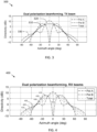
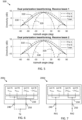
- Figures 3-5 are graphs 300, 400, 500 illustrating example antenna patterns in terms of antenna directivity (measured in dBi) vs azimuth angle in degrees. These graphs illustrate symmetric and even antenna patterns. It is, however, appreciated that the methods disclosed herein are also applicable to more uneven antenna power patterns comprising more than one direction associated with increased antenna gain.
- the antenna power pattern 310 may comprise one or more lobes, i.e., high gain directions, of varying width.
- Figure 3 illustrates directivity 300 for each of two example panel ports, e.g., as schematically illustrated in Figures 2A and 2B .
- the two polarizations are here referred to as polarization A 320 (pol A) and polarization B 330 (pol B).
- the directivity for the antenna port shown as 'Total' 310 in Figure 3 , is plotted under the assumption that the antenna ports are fed with equal power.
- the directivity for individual polarizations 320, 330 may fluctuate significantly with azimuth angle whereas the directivity for the antenna port 310 (defined by the beamforming weight vectors w) does not show such fluctuations but rather the desired beam shape.
- This antenna port is suitable for transmission since it generates an even and wide antenna beam.
- the antenna power pattern 310 in Figure 3 is an example of a desired antenna power pattern. It is appreciated that this antenna power pattern may be adapted to basically any desired antenna pattern.
- the antenna power pattern 310 may, e.g., be configured in dependence of a desired coverage area of the antenna array 111, 200a, 200b.
- Figure 4 shows an example of directivity for the antenna ports (pol A and pol B) and directivity for the antenna port assuming five different splits of power between the antenna ports due to variation in the polarization state of the impinging wave.
- a main concept of the herein disclosed techniques relates to the generation of at least two sets of virtualizations (or beam forming weight vectors) by means of DPBF.
- the virtualizations are based on an "array expansion technique" which enables different virtualizations to have identical power patterns despite these are connected to different number of antenna elements. This way a power efficient transmit beam is generated by the transmit port, and full-fledged diversity reception can be exploited using the signals on the two orthogonally polarized receiver ports.
- the transceiver 260 becomes insensitive to the polarization of the signals received from the wireless device 120 on the uplink (UL), resulting in that the received power is effectively the same no matter the polarization state of the UL signal.
- the fluctuations with azimuth angle as shown in the example of Figure 4 will be less pronounced and may even be removed entirely by signal processing in the transceiver 260.
- the herein proposed scheme includes the design of two sets of beamforming weight vectors, one set used for transmission of signals to the wireless device 120 and one set used for reception of signals from the wireless device 120.
- w A defines the beamforming weight vector applied to panel elements of polarization A and w B defines the beamforming weight vector applied to panel elements of polarization B, where polarization A is different or even orthogonal to polarization B.
- the beamforming weights used for transmission can, via an expansion technique, be based on beamforming weights for a smaller number of elements.
- This weight vector defines the desired antenna power pattern which will be generated both by the transmit port as well as by the receive ports.
- a wide beam may be desired, e.g., for transmission of the SSB in a 3GPP network, but other antenna power patterns may just as well be generated by adapting w RX 1 o by laboratory experiment or by computer simulation to the desired antenna power pattern.
- the desired antenna pattern may comprise one or more directions associated with increased gain.
- the desired antenna pattern may also comprise one or more directions associated with reduced gain, for instance in order to reduce co-cell interference in some directions.
- the matrix J is not the same size matrix on the two sides of the equality sign. To the left the dimension of J is N/2 x N/2 and to the right the dimension of J is N/4 x N/4. Note also that w RX 1 and w RX 2 both contain zeros in complementary positions, such that the sum of the weight vectors is rather to be seen as a combination of the weight vectors. Note also that the minus sign in ⁇ Jw A 1 o * represents a phase shift of ⁇ radians, which phase shift can be arbitrarily distributed between the two polarizations and over the elements.
- Figure 5 presents an example 500 of the antenna patterns according to the example discussed above.
- 'Total' here represents the directivity for the "antenna port" assuming that receive beam 1 has the same pattern for the first polarization (pol A) as receive beam 2 has for the second polarization (pol B).
- Receive beam 1 has the same antenna pattern for the second polarization (pol B) as receive beam 2 has for the first polarization (pol A).
- the two receive beams have the same patterns but orthogonal or at least significantly different polarizations.
- a dual polarized antenna array comprising antenna elements 210, 220 of a first polarization (pol A) and of a second polarization (pol B). Each antenna element is associated with a respective beamforming weight vector for communication with a wireless device 120.
- the antenna array comprises a configurable antenna feed network 230 which is arranged to provide a transmit antenna port TX by configuring a first set of beamforming weight vectors w TX 1 connecting the transmit port TX to antenna elements of the first and of the second polarization.
- the transmit antenna port TX is associated with an antenna power pattern 310.
- the antenna feed network 230 is also arranged to provide a first receive antenna port RX1 and a second receive antenna port RX2 by configuring a second set of beamforming weights w RX 1 connecting the first receive antenna port RX1 to antenna elements of the first and of the second polarization, and a third set of beamforming weights w RX 2 connecting the second receive antenna port RX2 to antenna elements of the first and of the second polarization.
- Each of the receive antenna ports RX1, RX2 is associated with the antenna power pattern 310, i.e., the same antenna pattern as the TX port, and the receive antenna ports RX1, RX2 have different polarizations.
- FIG. 6 schematically illustrates an example antenna array 200c configured for transmission via a single transmit port (TX).
- the feed network 230 here connects the first panel port 240 to elements of the first polarization (pol A) via beamforming weight vectors w A1 o and Jw B 1 o * .
- the feed network 230 also connects the second panel port 250 to elements of the second polarization (pol B) via beamforming weight vectors w B 1 o and ⁇ Jw A 1 o * .
- the feed network 230 may be an analogue feed network, or a digital feed network implemented in software, or a combination thereof.
- Figure 7 shows the example antenna array 200d now configured for reception.
- the feed network 230 change virtualizations or beamforming weights. This is not only a matter of changing beamforming weights within a polarization but also to be able to connect between polarizations.
- the feed network 230 of the antenna array 200d is configured for reception by changing associations between antenna ports of the antenna array and antenna elements of both the first and of the second polarization, compared to the configuration of the feed network for the antenna array 200c when configured for transmission.
- the antenna arrays 111, 200a, 200b, 200c, 200d discussed herein comprises N/2 antenna elements of the first polarization pol A and N/2 antenna elements of the second polarization pol B.
- the transmit antenna port TX is connected to all N antenna elements
- the first receive antenna port RX1 is connected to N/2 antenna elements out of the N elements
- the second receive antenna port RX2 is connected to the remaining N/2 antenna elements.
- the antenna array 111, 200a, 200b, 200c, 200d comprises N/2 antenna elements of the first polarization pol A and N/2 antenna elements of the second polarization pol B.
- the transmit antenna port TX is connected to all N antenna elements, and wherein the first and second receive antenna ports RX1, RX2 are both connected to all N antenna elements.
- Figure 8 shows a flowchart illustrating methods which summarize the discussions above.
- Figure 8 illustrates a method of configuring a dual polarized antenna array 111, 200a, 200b, 200c, 200d for communication between a wireless device 120 and a wireless access network 100, such as exemplified and discussed above in connection to Figure 1 .
- the antenna array 111, 200a, 200b, 200c, 200d comprises antenna elements 210, 220 with respective polarizations, where each antenna element is associated with a respective beamforming weight, e.g., as exemplified in Figures 2A and 2B .
- the disclosed method comprises configuring S1 the antenna array 111, 200a, 200b, 200c, 200d for transmission by a first set of beamforming weights w TX 1 , wherein the first set of beamforming weights, i.e., a beamforming vector, is arranged to provide a transmit antenna port TX connected to antenna elements of a first polarization pol A and of a second polarization pol B, wherein the transmit antenna port TX is associated with an antenna power pattern 310.
- the transmit port uses elements of both polarizations 320, 330 to generate an antenna power pattern 310, e.g., as exemplified in Figure 3 .
- the powers transmitted in the two polarizations fluctuate over beam angle, the sum of the two is relatively even, which in this case is as desired.
- any antenna power pattern may be used as base for the disclosed methods.
- the method also comprises transmitting S2 a first signal via the transmit antenna port TX on a downlink (DL) from the antenna array 111, 200a, 200b, 200c, 200d to the wireless device 120.
- DL downlink
- the method furthermore comprises configuring S3 the antenna array 111, 200a, 200b, 200c, 200d for reception by a second w RX 1 and a third w RX 2 set of beamforming weights, i.e., beamforming vectors.
- the second set of beamforming weights w RX 1 is arranged to provide a first receive antenna port RX1 connected to antenna elements of the first and of the second polarization
- the third set of beamforming weights w RX 2 is arranged to provide a second receive antenna port RX2 connected to antenna elements of the first and of the second polarization, where each of the receive antenna ports RX1, RX2 is associated with the antenna power pattern 310, and where the receive antenna ports RX1, RX2 have different polarizations.
- both receive ports are associated with the same antenna power pattern 310, which is also the antenna power pattern associated with the single transmit port.
- the method comprises receiving S4 a second signal on an uplink (UL) from the wireless device 120 to the antenna array 111, 200a, 200b, 200c, 200d, via the first receive antenna port RX1 and the second receive antenna port RX2.
- UL uplink
- the antenna power pattern 310 used for both transmission and reception may be an evenly distributed wide beam as discussed above. However, in some cases, other antenna power patterns may be desired. For instance, an antenna power pattern may be designed to cover some specific geographical region or part of a building.
- the configuring for transmission comprises configuring S12 the antenna power pattern in dependence of a desired coverage area of the first signal.
- the wireless access network 100 is a 3GPP defined network, and the transmitting comprises transmitting S21 a first signal comprising any of a synchronization signal block (SSB) signal, a tracking reference signal (TRS), a physical downlink control channel (PDCCH) message, a random access response (RAR) message, and/or a contention resolution message.
- SSB synchronization signal block
- TRS tracking reference signal
- PDCCH physical downlink control channel
- RAR random access response
- the wireless access network 100 is a 3GPP defined network, and the receiving comprises receiving S41 a second signal comprising any of an SSB response signal, a physical random access channel (PRACH) message, an msg3 message or radio resource control connection request, a channel state information (CSI) report, a physical uplink shared channel (PUSCH) message, and/or a physical uplink control channel (PUCCH) message.
- a second signal comprising any of an SSB response signal, a physical random access channel (PRACH) message, an msg3 message or radio resource control connection request, a channel state information (CSI) report, a physical uplink shared channel (PUSCH) message, and/or a physical uplink control channel (PUCCH) message.
- PRACH physical random access channel
- CSI channel state information
- PUSCH physical uplink shared channel
- PUCCH physical uplink control channel
- the configuring for reception comprises configuring S31 the first receive antenna port RX1 and the second receive antenna port RX2 to have mutually orthogonal polarizations.
- Configuring receive ports to have substantially orthogonal polarizations may improve receive conditions, which is an advantage.
- Most of the advantages mentioned herein associated with the disclosed methods and devices are obtained also for sufficiently different polarizations on the two receive ports.
- the configuring for reception comprises configuring S32 a feed network 230 of the antenna array 111, 200a, 200b, 200c, 200d by changing associations between antenna ports of the antenna array and antenna elements of both the first and of the second polarization.
- the method comprises combining S5 the second signal received via the first receive antenna port RX1 with the second signal received via the second receive antenna port RX2.
- the combining is based on a received signal quality on the first receive antenna port RX1 in relation to a received signal quality on the second receive antenna port RX2.
- Received signal quality may, e.g., comprise a signal to noise ratio (SNR), a signal to interference and noise ratio (SINR), or a received power metric such as received signal strength (RSS).
- SNR signal to noise ratio
- SINR signal to interference and noise ratio
- RSS received power metric
- MRC maximum ratio combining
- the antenna array 111, 200a, 200b, 200c, 200d comprises N/2 antenna elements of the first polarization pol A and N/2 antenna elements of the second polarization pol B.
- the method comprises connecting S13 the transmit antenna port TX to all N antenna elements, connecting the first receive antenna port RX1 to N/2 antenna elements out of the N elements, and connecting the second receive antenna port RX2 to the remaining N/2 antenna elements.
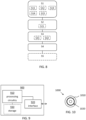
- FIG 9 schematically illustrates, in terms of a number of functional units, the components of a control unit 900 according to embodiments of the discussions herein.
- the control unit may, e.g., form part of an antenna array control unit 115 or a beamforming network controller for controlling a beamforming network such as the antenna feed network 230 discussed in connection to Figrues 2A and 2B.
- Processing circuitry 910 is provided using any combination of one or more of a suitable central processing unit CPU, multiprocessor, microcontroller, digital signal processor DSP, etc., capable of executing software instructions stored in a computer program product, e.g. in the form of a storage medium 930.
- the processing circuitry 910 may further be provided as at least one application specific integrated circuit ASIC, or field programmable gate array FPGA.
- the processing circuitry thus comprises a plurality of digital logic components.
- the processing circuitry 910 is configured to cause the system 130 to perform a set of operations, or steps.
- the storage medium 930 may store the set of operations
- the processing circuitry 910 may be configured to retrieve the set of operations from the storage medium 930 to cause the system 130 to perform the set of operations.
- the set of operations may be provided as a set of executable instructions.
- the processing circuitry 910 is thereby arranged to execute methods as herein disclosed.
- the storage medium 930 may also comprise persistent storage, which, for example, can be any single one or combination of magnetic memory, optical memory, solid state memory or even remotely mounted memory.
- the sensor signal processing system 130 further comprises an interface 920 for communications with at least one external device.
- the interface 920 may comprise one or more transmitters and receivers, comprising analogue and digital components and a suitable number of ports for wireline communication.
- the processing circuitry 910 controls the general operation of the system 130, e.g. by sending data and control signals to the interface 920 and the storage medium 930, by receiving data and reports from the interface 920, and by retrieving data and instructions from the storage medium 930.
- Other components, as well as the related functionality, of the control node are omitted in order not to obscure the concepts presented herein.
- Figure 10 shows a computer program product 1000 comprising computer executable instructions 1010 stored on media 1010 to execute any of the methods disclosed herein.
- the computer program 1020 may be set up for configuring a dual polarized antenna array 111, 200a, 200b, 200c, 200d for communication between a wireless device 120 and a wireless access network 100, wherein the antenna array 111, 200a, 200b, 200c, 200d comprises antenna elements 210, 220 with respective polarizations, and where each antenna element is associated with a respective beamforming weight, the computer program 1020 comprising computer code which, when run on an antenna array control unit 900, causes the antenna array to configure S1 the antenna array 111, 200a, 200b, 200c, 200d for transmission by a first set of beamforming weights w TX 1 , wherein the first set of beamforming weights is arranged to provide a transmit antenna port TX connected to antenna elements of a first polarization pol A and of a second polarization pol B, wherein the transmit antenna port TX is associated with an antenna power pattern 310, transmit S2 a first signal via the transmit antenna port TX on a downlink (DL) from
Landscapes
- Engineering & Computer Science (AREA)
- Computer Networks & Wireless Communication (AREA)
- Signal Processing (AREA)
- Variable-Direction Aerials And Aerial Arrays (AREA)
Claims (22)
- Verfahren zum Konfigurieren einer dual polarisierten Antennenanordnung (111, 200a, 200b, 200c, 200d) zur Kommunikation in einem drahtlosen Zugangsnetzwerk (100), wobei die Antennenanordnung (111, 200a, 200b, 200c, 200d) Antennenelemente (210, 220) mit jeweiligen Polarisationen und ein Antennenspeisenetzwerk (230) umfasst, wobei jedes Antennenelement mit einer jeweiligen Strahlformungsgewichtung assoziiert ist, wobei das Verfahren umfasstKonfigurieren (S1) der Antennenanordnung (111, 200a, 200b, 200c, 200d) zur Übertragung durch einen ersten Satz von Strahlformungsgewichtungen w TX1 , wobei der erste Satz von Strahlformungsgewichtungen mittels des Antennenspeisenetzwerks (230) angeordnet wird, um einen Übertragungsantennenanschluss (TX) bereitzustellen, der mit Antennenelementen einer ersten Polarisation (pol A) und einer zweiten Polarisation (pol B) verbunden ist, wobei der Übertragungsantennenanschluss (TX) mit einem Antennenleistungsdiagramm (310) assoziiert ist, wobei die jeweiligen Richtwirkungen der ersten und der zweiten Polarisation entlang des Antennenleistungsdiagramms, das mit dem Übertragungsantennenanschluss assoziiert ist, unterschiedlich variieren;Übertragen (S2) eines ersten Signals mittels des Übertragungsantennenanschlusses (TX) auf einer Abwärtsstrecke, DL, des drahtlosen Zugangsnetzwerks (100);Konfigurieren (S3) der Antennenanordnung (111, 200a, 200b, 200c, 200d) zum Empfang durch einen zweiten w RX1 und einen dritten w RX2 Satz von Strahlformungsgewichtungen, wobei der zweite Satz von Strahlformungsgewichtungen wRX1 mittels des Antennenspeisenetzwerks (230) angeordnet wird, um einen ersten Empfangsantennenanschluss (RX1) bereitzustellen, der mit Antennenelementen der ersten und der zweiten Polarisation verbunden ist, wobei der dritte Satz von Strahlformungsgewichtungen w RX2 mittels des Antennenspeisenetzwerks (230) angeordnet wird, um einen zweiten Empfangsantennenanschluss (RX2) bereitzustellen, der mit Antennenelementen der ersten und der zweiten Polarisation verbunden ist, wobei jeder der Empfangsantennenanschlüsse (RX1, RX2) mit dem Antennenleistungsdiagramm (310) assoziiert ist, wobei die jeweiligen Richtwirkungen der ersten und der zweiten Polarisation entlang der jeweiligen Antennenleistungsdiagramme, die mit dem ersten und dem zweiten Empfangsantennenanschluss assoziiert sind, unterschiedlich variieren und wobei die jeweiligen Variationen von Richtwirkungen des ersten und zweiten Empfangsantennenanschlusses (RX1, RX2) unterschiedlich sind; undEmpfangen (S4) eines zweiten Signals auf einer Aufwärtsstrecke, UL, des drahtlosen Zugangsnetzwerks (100) mittels des ersten Empfangsantennenanschlusses (RX1) und des zweiten Empfangsantennenanschlusses (RX2).
- Verfahren nach Anspruch 1, wobei das Konfigurieren Konfigurieren (S11) des Antennenleistungsdiagramms als ein Breitstrahldiagramm umfasst, das ein Winkelintervall zwischen 10-40 Grad und vorzugsweise etwa 15-30 Grad überspannt.
- Verfahren nach Anspruch 1 oder 2, wobei das Konfigurieren zur Übertragung Konfigurieren (S12) des Antennenleistungsdiagramms in Abhängigkeit eines gewünschten Abdeckungsbereichs des ersten Signals umfasst.
- Verfahren nach einem vorstehenden Anspruch, wobei das drahtlose Zugangsnetzwerk (100) ein definiertes Netzwerk des Partnerschaftsprogramms der dritten Generation, definiertes 3GPP-Netzwerk, ist, wobei das Übertragen Übertragen (S21) eines ersten Signals umfasst, das ein beliebiges von einem Signal eines Synchronisationssignalblocks, SSB-Signal, einem Nachvervolgungsreferenzsignal, TRS, einer Nachricht eines physikalischen Abwärtsstrecken-Steuerkanals, PDCCH-Nachricht, einer Direktzugriffantwort-, RAR-, Nachricht, und/oder einer Konfliktauflösungsnachricht umfasst.
- Verfahren nach einem vorstehenden Anspruch, wobei das Konfigurieren zum Empfang Konfigurieren (S31) des ersten Empfangsantennenanschlusses (RX1) und des zweiten Empfangsantennenanschlusses (RX2) umfasst, um wechselseitig orthogonale Polarisationen aufzuweisen.
- Verfahren nach einem vorstehenden Anspruch, wobei das Konfigurieren zum Empfang, verglichen mit der Konfiguration des Speisenetzwerks für die Antennenanordnung, wenn zur Übertragung konfiguriert, Konfigurieren (S32) des Speisenetzwerks (230) der Antennenanordnung (111, 200a, 200b, 200c, 200d) durch Ändern von Assoziationen zwischen Antennenanschlüssen der Antennenanordnung und Antennenelementen von sowohl der ersten als auch der zweiten Polarisation umfasst.
- Verfahren nach einem vorstehenden Anspruch, wobei das drahtlose Zugangsnetzwerk (100) ein definiertes Netzwerk des Partnerschaftsprogramms der dritten Generation, definiertes 3GPP-Netzwerk, ist, und wobei das Empfangen Empfangen (S41) eines zweiten Signals umfasst, das ein beliebiges von einem SSB-Antwortsignal, einer Nachricht eines Direktzugriffskanals, PRACH-Nachricht, einer msg3-Nachricht oder Verbindungsanfrage zur Steuerung von Funkressourcen, einem Bericht von Kanalstatusinformationen, CSI-Bericht, einer Nachricht eines geteilten physikalischen Aufwärtsstreckenkanals, PUSCH-Nachricht, und/oder einer Nachricht eines physikalischen Aufwärtsstrecken-Steuerkanals, PUCCH-Nachricht, umfasst.
- Verfahren nach einem vorstehenden Anspruch, umfassend Kombinieren (S5) des zweiten Signals, das mittels des ersten Empfangsantennenanschlusses (RX1) empfangen wurde, mit dem zweiten Signal, das mittels des zweiten Empfangsantennenanschlusses (RX2) empfangen wurde, wobei das Kombinieren auf einer Qualität des an dem ersten Empfangsantennenanschluss (RX1) empfangenen Signals in Bezug auf eine Qualität des an dem zweiten Empfangsantennenanschluss (RX2) empfangenen Signals basiert ist.
- Verfahren nach einem vorstehenden Anspruch, wobei die Antennenanordnung (111, 200a, 200b, 200c, 200d) N/2 Antennenelemente der ersten Polarisation (pol A) und N/2 Antennenelemente der zweiten Polarisation (pol B) umfasst, wobei das Verfahren Verbinden (S13) des Übertragungsantennenanschlusses (TX) mit allen N Antennenelementen, Verbinden des ersten Empfangsantennenanschlusses (RX1) mit N/2 Antennenelementen von den N Elementen und Verbinden des zweiten Empfangsantennenanschlusses (RX2) mit den verbleibenden N/2 Antennenelementen umfasst.
- Verfahren nach einem der Ansprüche 1-8, wobei die Antennenanordnung (111, 200a, 200b, 200c, 200d) N/2 Antennenelemente der ersten Polarisation (pol A) und N/2 Antennenelemente der zweiten Polarisation (pol B) umfasst, wobei das Verfahren Verbinden (S15) des Übertragungsantennenanschlusses (TX) mit allen N Antennenelementen und ebenfalls Verbinden des ersten und zweiten Empfangsantennenanschlusses (RX1, RX2) mit allen N Antennenelementen umfasst.
- Verfahren nach Anspruch 9, umfassend Definieren (S14) des Leistungsdiagramms (310) durch N/2 Strahlformungsgewichtungen





- Verfahren nach einem vorstehenden Anspruch, wobei das Verfahren von einer Antennenanordnungssteuerungseinheit (900) durchgeführt wird.
- Antennenanordnungssteuerungseinheit (115, 900), umfassend Verarbeitungsschaltung (910), die konfiguriert ist, um das Verfahren nach einem der Ansprüche 1-12 durchzuführen.
- Computerprogramm (1020) zum Konfigurieren einer dual polarisierten Antennenanordnung (111,
200a, 200b, 200c, 200d) zur Kommunikation zwischen einer drahtlosen Vorrichtung (120) und einem drahtlosen Zugangsnetzwerk (100), wobei die Antennenanordnung (111, 200a, 200b, 200c, 200d) Antennenelemente (210, 220) mit jeweiligen Polarisationen und ein Antennenspeisenetzwerk (230) umfasst, und wobei jedes Antennenelement mit einer jeweiligen Strahlformungsgewichtung assoziiert ist, wobei das Computerprogramm (1020) Computercode umfasst, der, wenn auf einer Antennenanordnungssteuerungseinheit (900) ausgeführt, die Antennenanordnung veranlasst:die Antennenanordnung (111, 200a, 200b, 200c, 200d) zur Übertragung durch einen ersten Satz von Strahlformungsgewichtungen w TX1 zu konfigurieren (S1), wobei der erste Satz von Strahlformungsgewichtungen mittels des Antennenspeisenetzwerks (230) angeordnet wird, um einen Übertragungsantennenanschluss (TX) bereitzustellen, der mit Antennenelementen einer ersten Polarisation (pol A) und einer zweiten Polarisation (pol B) verbunden ist, wobei der Übertragungsantennenanschluss (TX) mit einem Antennenleistungsdiagramm (310) assoziiert ist, wobei die jeweiligen Richtwirkungen der ersten und der zweiten Polarisation entlang des Antennenleistungsdiagramms, das mit dem Übertragungsantennenanschluss assoziiert ist, unterschiedlich variieren;ein erstes Signal mittels des Übertragungsantennenanschlusses (TX) auf einer Abwärtsstrecke, DL, von der Antennenanordnung (111, 200a, 200b, 200c, 200d) an die drahtlose Vorrichtung (120) zu übertragen (S2);die Antennenanordnung (111, 200a, 200b, 200c, 200d) zum Empfang durch einen zweiten w RX1 und einen dritten w RX2 Satz von Strahlformungsgewichtungen zu konfigurieren (S3), wobei der zweite Satz von Strahlformungsgewichtungen w RX1 mittels des Antennenspeisenetzwerks (230) angeordnet wird, um einen ersten Empfangsantennenanschluss (RX1) bereitzustellen, der mit Antennenelementen der ersten und der zweiten Polarisation verbunden ist, wobei der dritte Satz von Strahlformungsgewichtungen w RX2 mittels des Antennenspeisenetzwerks (230) angeordnet wird, um einen zweiten Empfangsantennenanschluss (RX2) bereitzustellen, der mit Antennenelementen der ersten und der zweiten Polarisation verbunden ist, wobei jeder der Empfangsantennenanschlüsse (RX1, RX2) mit dem Antennenleistungsdiagramm (310) assoziiert ist, wobei die jeweiligen Richtwirkungen der ersten und der zweiten Polarisation entlang der jeweiligen Antennenleistungsdiagramme, die mit dem ersten und dem zweiten Empfangsantennenanschluss assoziiert sind, unterschiedlich variieren und wobei die jeweiligen Variationen von Richtwirkungen des ersten und des zweiten Empfangsantennenanschlusses (RX1, RX2) unterschiedlich sind; und ummittels des ersten Empfangsantennenanschlusses (RX1) und des zweiten Empfangsantennenanschlusses (RX2) ein zweites Signal auf einer Aufwärtsstrecke, UL, von der drahtlosen Vorrichtung (120) an die Antennenanordnung (111, 200a, 200b, 200c, 200d) zu empfangen (S4). - Computerprogrammprodukt (1000), umfassend ein Computerprogramm (1020) nach Anspruch 14 und ein Computer-lesbares Mittel (1010), auf dem das Computerprogramm gespeichert ist.
- Dual polarisierte Antennenanordnung (111, 200a, 200b, 200c, 200d), umfassend Antennenelemente (210, 220) einer ersten Polarisation (pol A) und einer zweiten Polarisation (pol B), wobei jedes Antennenelement mit einer jeweiligen Strahlformungsgewichtung zur Kommunikation mit einer drahtlosen Vorrichtung (120) assoziiert ist, wobei die Antennenanordnung (111, 200a, 200b, 200c, 200d) ein konfigurierbares Antennenspeisenetzwerk (230) umfasst,wobei das Antennenspeisenetzwerk (230) angeordnet ist, um einen Übertragungsantennenanschluss (TX) durch Konfigurieren eines ersten Satzes von Strahlformungsgewichtungen w TX1 bereitzustellen, die den Übertragungsanschluss (TX) mit Antennenelementen der ersten und der zweiten Polarisation verbinden, wobei der Übertragungsantennenanschluss (TX) mit einem Antennenleistungsdiagramm (310) assoziiert ist, wobei die jeweiligen Richtwirkungen der ersten und der zweiten Polarisation entlang des Antennenleistungsdiagramms, das mit dem Übertragungsantennenanschluss assoziiert ist, unterschiedlich variieren,wobei das Antennenspeisenetzwerk (230) angeordnet ist, um einen ersten Empfangsantennenanschluss (RX1) und einen zweiten Empfangsantennenanschluss (RX2) durch Konfigurieren eines zweiten Satzes von Strahlformungsgewichtungen w RX1 , die den ersten Empfangsantennenanschluss (RX1) mit Antennenelementen der ersten und der zweiten Polarisation verbinden, und eines dritten w RX2 Satzes von Strahlformungsgewichtungen, die den zweiten Empfangsantennenanschluss (RX2) mit Antennenelementen der ersten und der zweiten Polarisation verbinden, bereitzustellen,wobei jeder der Empfangsantennenanschlüsse (RX1, RX2) mit dem Antennenleistungsdiagramm (310) assoziiert ist, wobei die jeweiligen Richtwirkungen der ersten und der zweiten Polarisation entlang der jeweiligen Antennenleistungsdiagramme, die mit dem ersten und dem zweiten Empfangsantennenanschluss assoziiert sind, unterschiedlich variieren, und wobei die jeweiligen Variationen von Richtwirkungen des ersten und des zweiten Empfangsantennenanschlusses (RX1, RX2) unterschiedlich sind.
- Dual polarisierte Antennenanordnung (111, 200a, 200b, 200c, 200d) nach Anspruch 16, wobei das Antennenleistungsdiagramm (310) ein Breitstrahldiagramm ist, das ein Winkelintervall zwischen 10-40 Grad und vorzugsweise etwa 15-30 Grad überspannt.
- Dual polarisierte Antennenanordnung (111, 200a, 200b, 200c, 200d) nach Anspruch 16 oder 17, wobei das Antennenleistungsdiagramm in Abhängigkeit eines gewünschten Abdeckungsbereichs der Antennenanordnung (111, 200a, 200b, 200c, 200d) konfiguriert ist.
- Dual polarisierte Antennenanordnung (111, 200a, 200b, 200c, 200d) nach einem der Ansprüche 16-18, wobei der erste Empfangsantennenanschluss (RX1) und der zweite Empfangsantennenanschluss (RX2) angeordnet sind, um wechselseitig orthogonale Polarisationen aufzuweisen.
- Dual polarisierte Antennenanordnung (111, 200a, 200b, 200c, 200d) nach einem der Ansprüche 16-19, wobei das Speisenetzwerk (230) der Antennenanordnung (111, 200a, 200b, 200c, 200d) verglichen mit der Konfiguration des Speisenetzwerks für die Antennenanordnung, wenn zur Übertragung konfiguriert, durch Ändern von Assoziationen zwischen Antennenanschlüssen der Antennenanordnung und Antennenelementen von sowohl der ersten als auch der zweiten Polarisation zum Empfang konfiguriert wird.
- Dual polarisierte Antennenanordnung (111, 200a, 200b, 200c, 200d) nach einem der Ansprüche 16-20, wobei die Antennenanordnung (111, 200a, 200b, 200c, 200d) N/2 Antennenelemente der ersten Polarisation (pol A) und N/2 Antennenelemente der zweiten Polarisation (pol B) umfasst, wobei der Übertragungsantennenanschluss (TX) mit allen N Antennenelementen verbunden ist, der erste Empfangsantennenanschluss (RX1) mit N/2 Antennenelementen von den N Elementen verbunden ist und der zweite Empfangsantennenanschlusses (RX2) mit den verbleibenden N/2 Antennenelementen verbunden ist.
- Dual polarisierte Antennenanordnung (111, 200a, 200b, 200c, 200d) nach einem der Ansprüche 16-21, wobei die Antennenanordnung (111, 200a, 200b, 200c, 200d) N/2 Antennenelemente der ersten Polarisation (pol A) und N/2 Antennenelemente der zweiten Polarisation (pol B) umfasst, wobei der Übertragungsantennenanschluss (TX) mit allen N Antennenelementen verbunden ist, und wobei der erste und zweite Empfangsantennenanschluss (RX1, RX2) beide mit allen N Antennenelementen verbunden sind.
Applications Claiming Priority (1)
| Application Number | Priority Date | Filing Date | Title |
|---|---|---|---|
| PCT/EP2020/063240 WO2021228376A1 (en) | 2020-05-12 | 2020-05-12 | Antenna beam virtualization for wide beam wireless communication |
Publications (2)
| Publication Number | Publication Date |
|---|---|
| EP4150779A1 EP4150779A1 (de) | 2023-03-22 |
| EP4150779B1 true EP4150779B1 (de) | 2023-09-06 |
Family
ID=70740600
Family Applications (1)
| Application Number | Title | Priority Date | Filing Date |
|---|---|---|---|
| EP20726345.0A Active EP4150779B1 (de) | 2020-05-12 | 2020-05-12 | Antennenstrahlvirtualisierung für drahtlose breitstrahlkommunikation |
Country Status (4)
| Country | Link |
|---|---|
| US (1) | US12034506B2 (de) |
| EP (1) | EP4150779B1 (de) |
| BR (1) | BR112022021752A2 (de) |
| WO (1) | WO2021228376A1 (de) |
Families Citing this family (4)
| Publication number | Priority date | Publication date | Assignee | Title |
|---|---|---|---|---|
| US12531626B2 (en) * | 2020-01-27 | 2026-01-20 | Qualcomm Incorporated | Asymmetric uplink-downlink beam training in frequency bands |
| US12075384B2 (en) * | 2020-08-28 | 2024-08-27 | Qualcomm Incorporated | Techniques for flexible reference signal patterns in wireless communications systems |
| EP4238229A1 (de) | 2020-10-30 | 2023-09-06 | Telefonaktiebolaget LM Ericsson (publ) | Kommunikation mit einer dualpolarisierten gruppenantenne |
| JP7590567B2 (ja) * | 2020-11-04 | 2024-11-26 | ケーエムダブリュ・インコーポレーテッド | 無線送受信装置 |
Family Cites Families (11)
| Publication number | Priority date | Publication date | Assignee | Title |
|---|---|---|---|---|
| US6304214B1 (en) | 1999-05-07 | 2001-10-16 | Lucent Technologies Inc. | Antenna array system having coherent and noncoherent reception characteristics |
| US6426726B1 (en) * | 2001-08-15 | 2002-07-30 | Northrop Grumman Corporation | Polarized phased array antenna |
| US6512480B1 (en) * | 2001-08-20 | 2003-01-28 | Vectrad Networks Corp. | System and method for narrow beam antenna diversity in an RF data transmission system |
| US20040157645A1 (en) * | 2003-02-12 | 2004-08-12 | Smith Adrian David | System and method of operation an array antenna in a distributed wireless communication network |
| US8737275B2 (en) * | 2009-06-01 | 2014-05-27 | Telefonaktiebolaget L M Ericsson (Publ) | Node in a wireless communication system with different antenna diversity methods for uplink and downlink |
| BR112012019194B1 (pt) * | 2010-02-08 | 2021-06-22 | Telefonaktiebolaget Lm Ericsson (Publ) | Antena com características de feixe ajustáveis |
| PH12013500795A1 (en) * | 2010-12-17 | 2013-06-17 | Ericsson Telefon Ab L M | Beamforming method, apparatus for polarized antenna array and radio communication device and system thereof |
| US10014916B2 (en) * | 2014-11-10 | 2018-07-03 | Samsung Electronics Co., Ltd. | 2D active antenna array operation for wireless communication systems |
| WO2016102010A1 (en) | 2014-12-23 | 2016-06-30 | Telefonaktiebolaget Lm Ericsson (Publ) | A method for beamforming a beam using an active antenna |
| CN107852211A (zh) * | 2015-08-07 | 2018-03-27 | 华为技术有限公司 | 模拟波束成形设备 |
| EP4030636A3 (de) | 2016-09-21 | 2022-09-21 | Telefonaktiebolaget LM Ericsson (publ) | Strahlformung von strahlen |
-
2020
- 2020-05-12 EP EP20726345.0A patent/EP4150779B1/de active Active
- 2020-05-12 BR BR112022021752A patent/BR112022021752A2/pt unknown
- 2020-05-12 WO PCT/EP2020/063240 patent/WO2021228376A1/en not_active Ceased
- 2020-05-12 US US17/924,583 patent/US12034506B2/en active Active
Also Published As
| Publication number | Publication date |
|---|---|
| BR112022021752A2 (pt) | 2022-12-06 |
| WO2021228376A1 (en) | 2021-11-18 |
| US12034506B2 (en) | 2024-07-09 |
| US20230179276A1 (en) | 2023-06-08 |
| EP4150779A1 (de) | 2023-03-22 |
Similar Documents
| Publication | Publication Date | Title |
|---|---|---|
| EP3117533B1 (de) | Rückkopplungsverfahren für strahlformung in einem drahtloskommunikationssystem und vorrichtung dafür | |
| US12034506B2 (en) | Antenna beam virtualization for wide beam wireless communication | |
| EP3123626B1 (de) | Verfahren zur durchführung einer hybriden strahlformung in einem drahtloskommunikationssystem und vorrichtung dafür | |
| US9893789B2 (en) | Method of transmitting a reference signal in a wireless communication system and apparatus therefor | |
| KR102345352B1 (ko) | 무선 통신 시스템에서 빔포밍을 위한 가중치 결정 방법 및 이를 위한 장치 | |
| EP3537753B1 (de) | Übertragungskonfigurationsverfahren, übertragungskonfigurationsbestimmungsverfahren, basisstation und endgerät | |
| US10305563B2 (en) | Massive antenna-based pattern/polarization beam division, multiple access method, and apparatus performing the same | |
| EP2961081B1 (de) | Verfahren zur übertragung eines signals in einem drahtlosen kommunikationssystem und vorrichtung dafür | |
| US20160380690A1 (en) | Wireless Communication Node With Adaptive Communication | |
| WO2016141961A1 (en) | Beam forming using an antenna arrangement | |
| Nam et al. | Full dimension MIMO for LTE-Advanced and 5G | |
| US9728850B2 (en) | Communication system node comprising a transformation matrix | |
| EP3472942B1 (de) | Flexible analogarchitektur zur sektorisierung | |
| JP7277601B2 (ja) | 方法および装置 | |
| US20210119676A1 (en) | Method For Simultaneous Design Of Hybrid Transceiver In OFDM-Based Wideband Multi-Antenna System | |
| EP3633873B1 (de) | Verfahren zur übertragung von rückkopplungsinformationen in einem drahtloskommunikationssystem und vorrichtung dafür | |
| US20150003548A1 (en) | Vertical Beam Design for UE-Specific Beamforming by Matching to a CB | |
| US12126412B2 (en) | Orientation-robust operation of tri-polarized antenna array | |
| CN106411373A (zh) | 一种天线阵列及基站发送信号的方法 | |
| EP4599524A1 (de) | Übertragung mehrerer vorrichtungen bei einer abdeckungsverbesserungsvorrichtung mit mehreren polarisationen | |
| Wang et al. | Beam-superposition-based multi-beam RSMA for hybrid mmWave systems | |
| Bharadwaj et al. | MIMO versus phased array antenna systems for 5G mobile communication systems | |
| CN213878438U (zh) | 实现波束的空间-极化分离的天线装置 | |
| US20250330233A1 (en) | Orientation-robust operation of planar tri-polarized antenna array | |
| Haskou et al. | An Efficient and Easy-to-Implement Method for SLL Reduction in RIS-Aided Systems |
Legal Events
| Date | Code | Title | Description |
|---|---|---|---|
| STAA | Information on the status of an ep patent application or granted ep patent |
Free format text: STATUS: UNKNOWN |
|
| STAA | Information on the status of an ep patent application or granted ep patent |
Free format text: STATUS: THE INTERNATIONAL PUBLICATION HAS BEEN MADE |
|
| PUAI | Public reference made under article 153(3) epc to a published international application that has entered the european phase |
Free format text: ORIGINAL CODE: 0009012 |
|
| STAA | Information on the status of an ep patent application or granted ep patent |
Free format text: STATUS: REQUEST FOR EXAMINATION WAS MADE |
|
| 17P | Request for examination filed |
Effective date: 20221110 |
|
| AK | Designated contracting states |
Kind code of ref document: A1 Designated state(s): AL AT BE BG CH CY CZ DE DK EE ES FI FR GB GR HR HU IE IS IT LI LT LU LV MC MK MT NL NO PL PT RO RS SE SI SK SM TR |
|
| GRAP | Despatch of communication of intention to grant a patent |
Free format text: ORIGINAL CODE: EPIDOSNIGR1 |
|
| STAA | Information on the status of an ep patent application or granted ep patent |
Free format text: STATUS: GRANT OF PATENT IS INTENDED |
|
| DAV | Request for validation of the european patent (deleted) | ||
| DAX | Request for extension of the european patent (deleted) | ||
| INTG | Intention to grant announced |
Effective date: 20230626 |
|
| GRAS | Grant fee paid |
Free format text: ORIGINAL CODE: EPIDOSNIGR3 |
|
| GRAA | (expected) grant |
Free format text: ORIGINAL CODE: 0009210 |
|
| STAA | Information on the status of an ep patent application or granted ep patent |
Free format text: STATUS: THE PATENT HAS BEEN GRANTED |
|
| AK | Designated contracting states |
Kind code of ref document: B1 Designated state(s): AL AT BE BG CH CY CZ DE DK EE ES FI FR GB GR HR HU IE IS IT LI LT LU LV MC MK MT NL NO PL PT RO RS SE SI SK SM TR |
|
| REG | Reference to a national code |
Ref country code: GB Ref legal event code: FG4D |
|
| REG | Reference to a national code |
Ref country code: CH Ref legal event code: EP |
|
| REG | Reference to a national code |
Ref country code: DE Ref legal event code: R096 Ref document number: 602020017232 Country of ref document: DE |
|
| REG | Reference to a national code |
Ref country code: IE Ref legal event code: FG4D |
|
| REG | Reference to a national code |
Ref country code: LT Ref legal event code: MG9D |
|
| REG | Reference to a national code |
Ref country code: NL Ref legal event code: MP Effective date: 20230906 |
|
| PG25 | Lapsed in a contracting state [announced via postgrant information from national office to epo] |
Ref country code: GR Free format text: LAPSE BECAUSE OF FAILURE TO SUBMIT A TRANSLATION OF THE DESCRIPTION OR TO PAY THE FEE WITHIN THE PRESCRIBED TIME-LIMIT Effective date: 20231207 |
|
| PG25 | Lapsed in a contracting state [announced via postgrant information from national office to epo] |
Ref country code: SE Free format text: LAPSE BECAUSE OF FAILURE TO SUBMIT A TRANSLATION OF THE DESCRIPTION OR TO PAY THE FEE WITHIN THE PRESCRIBED TIME-LIMIT Effective date: 20230906 Ref country code: RS Free format text: LAPSE BECAUSE OF FAILURE TO SUBMIT A TRANSLATION OF THE DESCRIPTION OR TO PAY THE FEE WITHIN THE PRESCRIBED TIME-LIMIT Effective date: 20230906 Ref country code: NO Free format text: LAPSE BECAUSE OF FAILURE TO SUBMIT A TRANSLATION OF THE DESCRIPTION OR TO PAY THE FEE WITHIN THE PRESCRIBED TIME-LIMIT Effective date: 20231206 Ref country code: LV Free format text: LAPSE BECAUSE OF FAILURE TO SUBMIT A TRANSLATION OF THE DESCRIPTION OR TO PAY THE FEE WITHIN THE PRESCRIBED TIME-LIMIT Effective date: 20230906 Ref country code: LT Free format text: LAPSE BECAUSE OF FAILURE TO SUBMIT A TRANSLATION OF THE DESCRIPTION OR TO PAY THE FEE WITHIN THE PRESCRIBED TIME-LIMIT Effective date: 20230906 Ref country code: HR Free format text: LAPSE BECAUSE OF FAILURE TO SUBMIT A TRANSLATION OF THE DESCRIPTION OR TO PAY THE FEE WITHIN THE PRESCRIBED TIME-LIMIT Effective date: 20230906 Ref country code: GR Free format text: LAPSE BECAUSE OF FAILURE TO SUBMIT A TRANSLATION OF THE DESCRIPTION OR TO PAY THE FEE WITHIN THE PRESCRIBED TIME-LIMIT Effective date: 20231207 Ref country code: FI Free format text: LAPSE BECAUSE OF FAILURE TO SUBMIT A TRANSLATION OF THE DESCRIPTION OR TO PAY THE FEE WITHIN THE PRESCRIBED TIME-LIMIT Effective date: 20230906 |
|
| REG | Reference to a national code |
Ref country code: AT Ref legal event code: MK05 Ref document number: 1609889 Country of ref document: AT Kind code of ref document: T Effective date: 20230906 |
|
| PG25 | Lapsed in a contracting state [announced via postgrant information from national office to epo] |
Ref country code: NL Free format text: LAPSE BECAUSE OF FAILURE TO SUBMIT A TRANSLATION OF THE DESCRIPTION OR TO PAY THE FEE WITHIN THE PRESCRIBED TIME-LIMIT Effective date: 20230906 |
|
| PG25 | Lapsed in a contracting state [announced via postgrant information from national office to epo] |
Ref country code: IS Free format text: LAPSE BECAUSE OF FAILURE TO SUBMIT A TRANSLATION OF THE DESCRIPTION OR TO PAY THE FEE WITHIN THE PRESCRIBED TIME-LIMIT Effective date: 20240106 |
|
| PG25 | Lapsed in a contracting state [announced via postgrant information from national office to epo] |
Ref country code: AT Free format text: LAPSE BECAUSE OF FAILURE TO SUBMIT A TRANSLATION OF THE DESCRIPTION OR TO PAY THE FEE WITHIN THE PRESCRIBED TIME-LIMIT Effective date: 20230906 |
|
| PG25 | Lapsed in a contracting state [announced via postgrant information from national office to epo] |
Ref country code: ES Free format text: LAPSE BECAUSE OF FAILURE TO SUBMIT A TRANSLATION OF THE DESCRIPTION OR TO PAY THE FEE WITHIN THE PRESCRIBED TIME-LIMIT Effective date: 20230906 |
|
| PG25 | Lapsed in a contracting state [announced via postgrant information from national office to epo] |
Ref country code: SM Free format text: LAPSE BECAUSE OF FAILURE TO SUBMIT A TRANSLATION OF THE DESCRIPTION OR TO PAY THE FEE WITHIN THE PRESCRIBED TIME-LIMIT Effective date: 20230906 Ref country code: RO Free format text: LAPSE BECAUSE OF FAILURE TO SUBMIT A TRANSLATION OF THE DESCRIPTION OR TO PAY THE FEE WITHIN THE PRESCRIBED TIME-LIMIT Effective date: 20230906 Ref country code: IS Free format text: LAPSE BECAUSE OF FAILURE TO SUBMIT A TRANSLATION OF THE DESCRIPTION OR TO PAY THE FEE WITHIN THE PRESCRIBED TIME-LIMIT Effective date: 20240106 Ref country code: ES Free format text: LAPSE BECAUSE OF FAILURE TO SUBMIT A TRANSLATION OF THE DESCRIPTION OR TO PAY THE FEE WITHIN THE PRESCRIBED TIME-LIMIT Effective date: 20230906 Ref country code: EE Free format text: LAPSE BECAUSE OF FAILURE TO SUBMIT A TRANSLATION OF THE DESCRIPTION OR TO PAY THE FEE WITHIN THE PRESCRIBED TIME-LIMIT Effective date: 20230906 Ref country code: CZ Free format text: LAPSE BECAUSE OF FAILURE TO SUBMIT A TRANSLATION OF THE DESCRIPTION OR TO PAY THE FEE WITHIN THE PRESCRIBED TIME-LIMIT Effective date: 20230906 Ref country code: AT Free format text: LAPSE BECAUSE OF FAILURE TO SUBMIT A TRANSLATION OF THE DESCRIPTION OR TO PAY THE FEE WITHIN THE PRESCRIBED TIME-LIMIT Effective date: 20230906 Ref country code: PT Free format text: LAPSE BECAUSE OF FAILURE TO SUBMIT A TRANSLATION OF THE DESCRIPTION OR TO PAY THE FEE WITHIN THE PRESCRIBED TIME-LIMIT Effective date: 20240108 Ref country code: SK Free format text: LAPSE BECAUSE OF FAILURE TO SUBMIT A TRANSLATION OF THE DESCRIPTION OR TO PAY THE FEE WITHIN THE PRESCRIBED TIME-LIMIT Effective date: 20230906 |
|
| PG25 | Lapsed in a contracting state [announced via postgrant information from national office to epo] |
Ref country code: PL Free format text: LAPSE BECAUSE OF FAILURE TO SUBMIT A TRANSLATION OF THE DESCRIPTION OR TO PAY THE FEE WITHIN THE PRESCRIBED TIME-LIMIT Effective date: 20230906 Ref country code: IT Free format text: LAPSE BECAUSE OF FAILURE TO SUBMIT A TRANSLATION OF THE DESCRIPTION OR TO PAY THE FEE WITHIN THE PRESCRIBED TIME-LIMIT Effective date: 20230906 |
|
| REG | Reference to a national code |
Ref country code: DE Ref legal event code: R097 Ref document number: 602020017232 Country of ref document: DE |
|
| PGFP | Annual fee paid to national office [announced via postgrant information from national office to epo] |
Ref country code: GB Payment date: 20240527 Year of fee payment: 5 |
|
| PG25 | Lapsed in a contracting state [announced via postgrant information from national office to epo] |
Ref country code: DK Free format text: LAPSE BECAUSE OF FAILURE TO SUBMIT A TRANSLATION OF THE DESCRIPTION OR TO PAY THE FEE WITHIN THE PRESCRIBED TIME-LIMIT Effective date: 20230906 |
|
| PLBE | No opposition filed within time limit |
Free format text: ORIGINAL CODE: 0009261 |
|
| STAA | Information on the status of an ep patent application or granted ep patent |
Free format text: STATUS: NO OPPOSITION FILED WITHIN TIME LIMIT |
|
| PG25 | Lapsed in a contracting state [announced via postgrant information from national office to epo] |
Ref country code: DK Free format text: LAPSE BECAUSE OF FAILURE TO SUBMIT A TRANSLATION OF THE DESCRIPTION OR TO PAY THE FEE WITHIN THE PRESCRIBED TIME-LIMIT Effective date: 20230906 Ref country code: SI Free format text: LAPSE BECAUSE OF FAILURE TO SUBMIT A TRANSLATION OF THE DESCRIPTION OR TO PAY THE FEE WITHIN THE PRESCRIBED TIME-LIMIT Effective date: 20230906 |
|
| 26N | No opposition filed |
Effective date: 20240607 |
|
| PG25 | Lapsed in a contracting state [announced via postgrant information from national office to epo] |
Ref country code: BG Free format text: LAPSE BECAUSE OF FAILURE TO SUBMIT A TRANSLATION OF THE DESCRIPTION OR TO PAY THE FEE WITHIN THE PRESCRIBED TIME-LIMIT Effective date: 20230906 |
|
| PG25 | Lapsed in a contracting state [announced via postgrant information from national office to epo] |
Ref country code: BG Free format text: LAPSE BECAUSE OF FAILURE TO SUBMIT A TRANSLATION OF THE DESCRIPTION OR TO PAY THE FEE WITHIN THE PRESCRIBED TIME-LIMIT Effective date: 20230906 |
|
| REG | Reference to a national code |
Ref country code: CH Ref legal event code: PL |
|
| PG25 | Lapsed in a contracting state [announced via postgrant information from national office to epo] |
Ref country code: MC Free format text: LAPSE BECAUSE OF FAILURE TO SUBMIT A TRANSLATION OF THE DESCRIPTION OR TO PAY THE FEE WITHIN THE PRESCRIBED TIME-LIMIT Effective date: 20230906 |
|
| PG25 | Lapsed in a contracting state [announced via postgrant information from national office to epo] |
Ref country code: LU Free format text: LAPSE BECAUSE OF NON-PAYMENT OF DUE FEES Effective date: 20240512 |
|
| PG25 | Lapsed in a contracting state [announced via postgrant information from national office to epo] |
Ref country code: MC Free format text: LAPSE BECAUSE OF FAILURE TO SUBMIT A TRANSLATION OF THE DESCRIPTION OR TO PAY THE FEE WITHIN THE PRESCRIBED TIME-LIMIT Effective date: 20230906 Ref country code: LU Free format text: LAPSE BECAUSE OF NON-PAYMENT OF DUE FEES Effective date: 20240512 Ref country code: CH Free format text: LAPSE BECAUSE OF NON-PAYMENT OF DUE FEES Effective date: 20240531 |
|
| REG | Reference to a national code |
Ref country code: BE Ref legal event code: MM Effective date: 20240531 |
|
| PG25 | Lapsed in a contracting state [announced via postgrant information from national office to epo] |
Ref country code: IE Free format text: LAPSE BECAUSE OF NON-PAYMENT OF DUE FEES Effective date: 20240512 |
|
| PG25 | Lapsed in a contracting state [announced via postgrant information from national office to epo] |
Ref country code: BE Free format text: LAPSE BECAUSE OF NON-PAYMENT OF DUE FEES Effective date: 20240531 |
|
| PG25 | Lapsed in a contracting state [announced via postgrant information from national office to epo] |
Ref country code: FR Free format text: LAPSE BECAUSE OF NON-PAYMENT OF DUE FEES Effective date: 20240531 |
|
| PGFP | Annual fee paid to national office [announced via postgrant information from national office to epo] |
Ref country code: DE Payment date: 20250529 Year of fee payment: 6 |
|
| PG25 | Lapsed in a contracting state [announced via postgrant information from national office to epo] |
Ref country code: CY Free format text: LAPSE BECAUSE OF FAILURE TO SUBMIT A TRANSLATION OF THE DESCRIPTION OR TO PAY THE FEE WITHIN THE PRESCRIBED TIME-LIMIT; INVALID AB INITIO Effective date: 20200512 |
|
| PG25 | Lapsed in a contracting state [announced via postgrant information from national office to epo] |
Ref country code: HU Free format text: LAPSE BECAUSE OF FAILURE TO SUBMIT A TRANSLATION OF THE DESCRIPTION OR TO PAY THE FEE WITHIN THE PRESCRIBED TIME-LIMIT; INVALID AB INITIO Effective date: 20200512 |
|
| GBPC | Gb: european patent ceased through non-payment of renewal fee |
Effective date: 20250512 |
|
| PG25 | Lapsed in a contracting state [announced via postgrant information from national office to epo] |
Ref country code: GB Free format text: LAPSE BECAUSE OF NON-PAYMENT OF DUE FEES Effective date: 20250512 |