EP4150683B1 - Electrode for a lithium-ion battery and process for its preparation - Google Patents
Electrode for a lithium-ion battery and process for its preparation Download PDFInfo
- Publication number
- EP4150683B1 EP4150683B1 EP21724331.0A EP21724331A EP4150683B1 EP 4150683 B1 EP4150683 B1 EP 4150683B1 EP 21724331 A EP21724331 A EP 21724331A EP 4150683 B1 EP4150683 B1 EP 4150683B1
- Authority
- EP
- European Patent Office
- Prior art keywords
- cathode
- sebs
- electrode
- active material
- anode
- Prior art date
- Legal status (The legal status is an assumption and is not a legal conclusion. Google has not performed a legal analysis and makes no representation as to the accuracy of the status listed.)
- Active
Links
Images


Classifications
-
- H—ELECTRICITY
- H01—ELECTRIC ELEMENTS
- H01M—PROCESSES OR MEANS, e.g. BATTERIES, FOR THE DIRECT CONVERSION OF CHEMICAL ENERGY INTO ELECTRICAL ENERGY
- H01M10/00—Secondary cells; Manufacture thereof
- H01M10/05—Accumulators with non-aqueous electrolyte
- H01M10/052—Li-accumulators
- H01M10/0525—Rocking-chair batteries, i.e. batteries with lithium insertion or intercalation in both electrodes; Lithium-ion batteries
-
- H—ELECTRICITY
- H01—ELECTRIC ELEMENTS
- H01M—PROCESSES OR MEANS, e.g. BATTERIES, FOR THE DIRECT CONVERSION OF CHEMICAL ENERGY INTO ELECTRICAL ENERGY
- H01M4/00—Electrodes
- H01M4/02—Electrodes composed of, or comprising, active material
-
- H—ELECTRICITY
- H01—ELECTRIC ELEMENTS
- H01M—PROCESSES OR MEANS, e.g. BATTERIES, FOR THE DIRECT CONVERSION OF CHEMICAL ENERGY INTO ELECTRICAL ENERGY
- H01M4/00—Electrodes
- H01M4/02—Electrodes composed of, or comprising, active material
- H01M4/04—Processes of manufacture in general
- H01M4/0402—Methods of deposition of the material
- H01M4/0404—Methods of deposition of the material by coating on electrode collectors
-
- H—ELECTRICITY
- H01—ELECTRIC ELEMENTS
- H01M—PROCESSES OR MEANS, e.g. BATTERIES, FOR THE DIRECT CONVERSION OF CHEMICAL ENERGY INTO ELECTRICAL ENERGY
- H01M4/00—Electrodes
- H01M4/02—Electrodes composed of, or comprising, active material
- H01M4/04—Processes of manufacture in general
- H01M4/0402—Methods of deposition of the material
- H01M4/0414—Methods of deposition of the material by screen printing
-
- H—ELECTRICITY
- H01—ELECTRIC ELEMENTS
- H01M—PROCESSES OR MEANS, e.g. BATTERIES, FOR THE DIRECT CONVERSION OF CHEMICAL ENERGY INTO ELECTRICAL ENERGY
- H01M4/00—Electrodes
- H01M4/02—Electrodes composed of, or comprising, active material
- H01M4/04—Processes of manufacture in general
- H01M4/0471—Processes of manufacture in general involving thermal treatment, e.g. firing, sintering, backing particulate active material, thermal decomposition, pyrolysis
-
- H—ELECTRICITY
- H01—ELECTRIC ELEMENTS
- H01M—PROCESSES OR MEANS, e.g. BATTERIES, FOR THE DIRECT CONVERSION OF CHEMICAL ENERGY INTO ELECTRICAL ENERGY
- H01M4/00—Electrodes
- H01M4/02—Electrodes composed of, or comprising, active material
- H01M4/13—Electrodes for accumulators with non-aqueous electrolyte, e.g. for lithium-accumulators; Processes of manufacture thereof
- H01M4/139—Processes of manufacture
- H01M4/1391—Processes of manufacture of electrodes based on mixed oxides or hydroxides, or on mixtures of oxides or hydroxides, e.g. LiCoOx
-
- H—ELECTRICITY
- H01—ELECTRIC ELEMENTS
- H01M—PROCESSES OR MEANS, e.g. BATTERIES, FOR THE DIRECT CONVERSION OF CHEMICAL ENERGY INTO ELECTRICAL ENERGY
- H01M4/00—Electrodes
- H01M4/02—Electrodes composed of, or comprising, active material
- H01M4/62—Selection of inactive substances as ingredients for active masses, e.g. binders, fillers
- H01M4/621—Binders
- H01M4/622—Binders being polymers
-
- Y—GENERAL TAGGING OF NEW TECHNOLOGICAL DEVELOPMENTS; GENERAL TAGGING OF CROSS-SECTIONAL TECHNOLOGIES SPANNING OVER SEVERAL SECTIONS OF THE IPC; TECHNICAL SUBJECTS COVERED BY FORMER USPC CROSS-REFERENCE ART COLLECTIONS [XRACs] AND DIGESTS
- Y02—TECHNOLOGIES OR APPLICATIONS FOR MITIGATION OR ADAPTATION AGAINST CLIMATE CHANGE
- Y02E—REDUCTION OF GREENHOUSE GAS [GHG] EMISSIONS, RELATED TO ENERGY GENERATION, TRANSMISSION OR DISTRIBUTION
- Y02E60/00—Enabling technologies; Technologies with a potential or indirect contribution to GHG emissions mitigation
- Y02E60/10—Energy storage using batteries
Definitions
- the molecular weight of the polystyrene block, polyethylene/butylene block and that of the SEBS are controlled by the ratio and amount of monomers styrene and or butadiene relative to moles of initiator during the anionic polymerization reaction.
- the thickness of the separator is preferably from 0.5 to 40 ⁇ m, more preferably from 1 to 30 ⁇ m, and still more preferably from 1 to 25 ⁇ m from a viewpoint of reducing a resistance due to the separator in a lithium-ion secondary battery and excellent workability in manufacturing the lithium-ion secondary battery with degree of porosity between 40 and 60% .
- the following relative amounts of the solid components were used: 80% active material, 10% polymer binder and 10% conductive additive.
- the total solid content i.e. the total amount of active material, polymer binder and conductive additive, was 40 wt% of the ink cathode formulation.
- the polymer binder content was 6 wt% of the ink cathode formulation.
- a constant volume (1.5 mL) of sample was loaded in a stress controlled rotational rheometer (ARG2, TA Instruments) equipped with 40 mm diameter plates coated with sandpaper to limit wall slip.
- An automatic gap setting protocol with constant travelling speed of plates from back-off distance to sample thickness, was used to produce a similar flow history during sample loading.
- the shearing geometry was tapped with water to avoid any solvent loss during testing.
- a new sample was loaded in the rheometer for each thickness tested.
- a conditioning step (0.5 s -1 steady shear) was first applied to induce the same shear history on each sample. The duration of the step was 60 s to ensure the reading of a steady shear viscosity for all samples.
- the cathodes morphology was evaluated by scanning electron microscopy (SEM) with a NanoSEM-FEI Nova 200 equipment, at different magnifications (25 000 X and 120 000 X) and an acceleration voltage of 10 kV.
- the adhesion between the cathode and the current collector was evaluated as well as the cathode film cohesion and flexibility.
- a homemade "bend tester" with different diameter metal rods between 10.0 mm and 1.5 mm was used.
- three measurements were performed, as explained in Gören A. et al. 2015.
- Figure 2 depicts the extent of reproducibility of the rheological data measured with sample SEBS C-H6110/M3 (Comparative Example 3) in which four tests performed with different sample thickness are reported.
- a qualitatively similar set of data was measured with samples SEBS C-H6110/M1 (Comparative Example 1; see section above) and SEBS C-H6110/M2 (Comparative Example 4).
- SEBS C-H6110/M1 Comparative Example 1; see section above
- SEBS C-H6110/M2 Comparative Example 4
- Figure 3 presents the mean values and error bars of rheological functions computed from the data of four tests performed at different thicknesses. Overall, data displayed in Figure 3 reveal that rheological properties are sensitive to the method used to prepare the three inks.
- sample SEBS C.H6110/M3 shows longer structural build-up after steady shear cessation.
- Figure 3a indicates that G' for sample SEBS C-H61 10/M1 reaches a structural equilibrium at 1000 s after an initial power law behavior typical of glassy or gelled colloidal dispersions.
- the structure of sample SEBS C-H6110/M3 continues to recover after 2000 s and an equilibrium is barely reached within 1 hour.
- Sample SEBS C-H6110/M2 shows an intermediate kinetics.
- the homogeneous structure of the printed cathode plays an important role in battery performance.
- the morphological homogeneity of the samples was thus evaluated by SEM measurements ( Figure 4 ). A good particle distribution is verified in all printed cathodes showing that the ink properties are suitable for screen-printing technique. Aggregation of the components is also not visible in all samples.
- the images show a three-dimensional interconnected structure of all the three battery components (binder, conductive additive and active material). Also evident in all samples is the non-spherical shape of the active material particles, which exhibit a rod like structure with heterogeneous sizes in the order of 2 ⁇ m. The presence of voids along the electrode surface is evident (porosity) and attributed to the solvent evaporation and the difference in particles sizes and shapes. This porosity allows the lithium-ion access to the cathode, increasing the interface area between the electrode and the electrolyte, favoring the intercalation kinetics.
- Figures 4a, b and c show that, once the same dispersion method is applied, the morphology is not depending on the chemical structure of the binder. Comparing the SBS sample ( Figure 4a ; i.e. Comparative example 2) and the SEBS samples ( Figures 4b and c, i.e. Example 1 and Comparative example 1, respectively) prepared using Method 1, one may conclude that the dry mixing of active and conductive additives lead to a similar degree of particle dispersion. Therefore, the presence of ethylene blocks in the SEBS copolymer (not present in the SBS) and the styrene percentage do not affect the cathode morphology since the cathode's porosity (around 70%) and the microstructure are the same.
- the DC electrical conductivity is around 10 S.m -1 for the different polymers with the same method dispersion. According to this, a good structural distribution is achieved within the different polymers studied, promoting a good mechanical stability and good cohesion between the different particles.
- the electrical conductivity measurements were performed by the four point probe method with a current source DC 9818 from Time Electronics and a nano-voltmeter 2182 from Keithley.
- Figures 4c, d and e show significant differences in the particle distribution for the samples prepared with inks formulated after the different preparation methods.
- the sample prepared with Method 2 shows that polymer particles are covering the active and conductive particles.
- the presence of copolymer particles can be explained by the fact that, once the particles are first dispersed in the solvent, the resulting slurry has a significant viscosity, which is detrimental to the full solvation of the copolymer.
- the mixing time of the copolymer in the ink is reduced when compared to the two other methods.
- the polymer coating of particles influences not only the mechanical but also the DC electrical conductivity, as electrical connectivity between active materials is promoted.
- the DC electrical conductivity is 19.6 ⁇ 0.9 S.m -1 , that is higher than for the inks prepared by different methods: 8.4 ⁇ 1.5 and 15.7 ⁇ 1.0 S.m -1 for SEBS C-H6110/M1 and SEBS C-H6110/M3, respectively.
- the samples show the same 70% of porosity percentage.
- the cycle stability of the printed cathodes was evaluated after 50 charge/discharge cycles at C- and 2C-rates ( Figure 5c ), all samples showing good stability and high capacity retention over cycling and scan rates.
- the capacity retention after 50 cycles at 2C for the cathodes with the different polymers binders is 85, 93 and 100% for SEBS C-H6110/M1, SBS C-718/M1 and SEBS C-H6180X/M1, respectively.
- the capacity fade between the 2 nd and 50 th cycle was calculated, and it is 40%, 5% and 7% for SEBS C-H6110/M1, SBS C-718/M1 and SEBS C-H6180X/M1, respectively.
Landscapes
- Chemical & Material Sciences (AREA)
- Engineering & Computer Science (AREA)
- Chemical Kinetics & Catalysis (AREA)
- Electrochemistry (AREA)
- General Chemical & Material Sciences (AREA)
- Manufacturing & Machinery (AREA)
- Materials Engineering (AREA)
- Battery Electrode And Active Subsutance (AREA)
- Secondary Cells (AREA)
Description
- This application claims the benefit of European Patent Application
EP20382398.4 filed on May 13th, 2020 - The present disclosure relates to the field of rechargeable batteries. In particular, it relates to an electrode comprising a linear styrene-ethylene/butylene-styrene (SEBS) copolymer as a binder, and to a Li-ion battery comprising said electrode. More particularly, it relates to a cathode, to an anode, as well as to a process for their preparation.
- Increasing mobility, sensing and interconnection needs is driving the need for low cost and environmentally friendly energy storage systems.
- Lithium-ion batteries represent an advantageous technology for this purpose, due to the high volumetric (Wh·L-1) and gravimetric (Wh·g-1) energy densities when compared with other conventional electrochemical batteries. In addition, they also show several attractive features, such as the lack of memory effect, low self-discharge, high number of charge and discharge cycles and high energy efficiency in the process of energy conversion. Lithium-ion batteries are suitable for the integration in portable devices (smartphones, laptops, tablets) and smart sensors/actuators, very relevant in the "Internet of Things" (IoT), contributing to the rapid implementation of the concepts of smart home, smart city and point of care biomedical devices. It also represents a reliable technology for the integration in electric and hybrids vehicles, off-grid power systems in isolated areas, and uninterruptible power supplies (UPS).
- Cathodes for lithium-ion batteries are prepared from a slurry, which is coated on a metal current collector substrate (aluminum). This slurry consists in the mixture of an active material, a binder, a conductive additive and a solvent.
- One of the possible polymers that can be used as a binder belongs to the family of styrene block copolymers (SBC). Styrene-butadiene-styrene (SBS) copolymer is widely used in industry as it sustains high elongations, shows abrasion resistance, durability and chemical resistance. Styrene-ethylene/butylene-styrene (SEBS) copolymer, obtained by the hydrogenation of the SBS polymer, has a higher resistance to temperature and ultraviolet radiation, as well as improved elastic properties. Additionally, SEBS copolymer is non-toxic, with no cytotoxicity effects, even after the natural aging process.
- In a recent study, SEBS was shown to be a very attractive polymer binder for Li-ion batteries (cf. Gonçalves, R. et al. "Poly(styrene-butene/ethylene-styrene): A New Polymer Binder for High-Performance Printable Lithium-Ion Battery Electrodes", ACS Applied Energy Materials, 2018, Vol. 1, pp. 3331-3341), in which a full battery was assembled with screen-printed electrodes (both anode and cathode). The printed cathode battery performance was evaluated, showing a high delivery capacity between 137 mAh g-1 (at C/5) and 52 mAh g-1 (at 5C) for the different cycle numbers. SEBS based inks formulated for screen printing showed a homogeneous particle distribution, results also proving that SEBS based polymer binders provides a better interface structure than the commonly used PVDF polymer binder.
- The inventors have realized that by using a linear styrene-ethylene/butylene-styrene (SEBS) copolymer having a high melt flow rate, a relatively low molecular weight and styrene content as binder in the active layer of an electrode (either of a cathode, of an anode or of both of them), batteries having better performances, particularly having an improved specific capacity can be manufactured.
- Thus, a first aspect of the invention relates to an electrode for a lithium-ion battery comprising an active layer comprising an electrode active material; a conductive additive; and a linear styrene-ethylene/butylene-styrene (SEBS) copolymer as a binder which is characterized by having:
- a melt flow rate (MFR) measured at 230 °C and 2.16 kg load from 4 to 220 g/10 min;
- a molecular weight of less than 100,000 g/mol, particularly from 50,000 g/mol to 100,000 g/mol and;
- a styrene content from 10 to 20 wt. %.
- A second aspect of the invention relates to a process for the preparation of an electrode as defined above, the process comprising:
- a) obtaining a slurry comprising
- a linear styrene-ethylene/butylene-styrene (SEBS) copolymer as a binder which is characterized by having:
- a melt flow rate (MFR) measured at 230 °C and 2.16 kg load from 4 to 220 g/10 min such as of 4 g/10 min, 10 g/10 min, 30 g/10 min, 50 g/10 min, 100 g/10 min, or 150 g/10 min;
- a molecular weight of less than 100,000 g/mol, particularly from 50,000 g/mol to 100,000 g/mol such as of 70,000 g/mol, or 75,000 g/mol, or 80,000 g/mol and;
- a styrene content from 10 to 20 wt. % such as of 15 wt. %;
- an electrode active material, a conductive additive, and a suitable solvent; and
- a linear styrene-ethylene/butylene-styrene (SEBS) copolymer as a binder which is characterized by having:
- b) applying the slurry to a current collector; and
- c) drying the applied slurry in order to form an electrode active layer on the current collector.
- A third aspect of the invention relates to a Li-ion battery comprising a cathode, anode, a separator, and a suitable electrolytic solution interposed between the cathode and the anode, wherein either the cathode, or the anode, or both of them are as defined above.
-
-
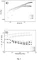
Fig. 1 shows the rheological characterization of sample with SEBS C-H6180X (triangles; Example 1), sample with SEBS C-H6110 (squares; Comparative example 1), and sample with SBS C-718 (circles; Comparative example 2) prepared usingMethod 1. a) Viscosity response to a steady shear of 0.5 s-1. b) Time evolution of storage modulus G' after steady shear cessation. c) Mechanical spectra recorded at the end of the time evolution (G': empty symbols; G": solid symbols). d) Stress dependence of G' (empty symbols) and G" (solid symbols). Symbols indicate the mean values from tests performed with 4 different sample thickness for each ink. -
Fig. 2 shows the rheological characterization of sample SEBS C-H6110/M3 at different thicknesses: 800 µm (left triangles), 817 µm (circles), 820 µm (diamonds) and 980 µm (up triangles), a) Mechanical spectra recorded at the end of the time evolution (G': empty symbols; G": solid symbols). b) Oscillatory strain response to large amplitude oscillatory stresses with 1 Hz frequency. -
Figure 3 shows: a) Time dependence of the shear storage modulus G' of ink SEBS C-H6110/M1 (squares), ink SEBS C-H6110/M2 (circles) and ink SEBS C-H6110/ M3 (triangles) measured after cessation of 60 s steady shear at a shear rate of 0.5 s-1. b) Mechanical spectra (G': open symbols; G": filled symbols) of ink SEBS C-H6110/ M1 (triangles), ink SEBS C-H6110/M2 (circles) and ink SEBS C-H6110/ M3 (squares), c) Stress dependence of storage (G': open symbols) and loss (G": solid symbols) moduli of samples SEBS C-H6110/M1 (triangles), ink SEBS C-H6110/M2 (circles) and SEBS C-H6110/M3 (squares) measured during large amplitude oscillatory shear (LAOS) stress sweeps. -
Figure 4 shows the SEM surface images of the cathodes with the different polymer binders and methods: a) SBS C-718/M1, b) SEBS C-H6180X/M1, c) SEBS C-H6110/M1, d) SEBS C-H6110/M2 and e) SEBS C-H6110/M3. -
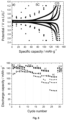
Figure 5 shows a) Fifth charge/discharge cycle profiles at C5 and C/5 rates. b) Rate performance for discharge profiles at C-rates between 5C and C/5. c) Cycle life stability at C- and 2C-rate. d) Coulombic efficiency as a function of cycle number. All measurements were performed at room temperature for all printed cathodes prepared by the different polymers and dispersion method (represented by squares for sample SBS C-718/M1, circles for sample SEBS C-H6180X/M1, triangles for sample SEBS C-H6110/M1, stars for SEBS C-H6110/M2, and rhombi for sample SEBS C-H6110/M3). -
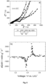
Figure 6 shows a) EIS results after cycling and the corresponding equivalent circuit and b) Differential capacity (dQ/dV) results for all printed cathodes prepared by the different polymers and dispersion method (represented by squares for sample SBS C-718/M1, circles for sample SEBS C-H6180X/M1, triangles for sample SEBS C-H6110/M1, stars for SEBS C-H6110/M2, and rhombi for sample SEBS C-H6110/M3). - All terms as used herein in this application, unless otherwise stated, shall be understood in their ordinary meaning as known in the art. Other more specific definitions terms as used in the present application are as set forth below and are intended to apply uniformly throughout the specification and claims unless an otherwise expressly set out definition provides a broader definition.
- The term "C-rate" as used herein, refers to a measure of the rate at which a battery is discharged relative to its maximum capacity. A 1C rate means that the discharge current will discharge the entire battery in 1 hour.
- The term "specific capacity" refers to the amount of charge stored and delivered (A·h) for a weight of the electrode active material, typically expressed in mAh/g, wherein the g relates to the g of active material.
- The term "percentage by weight (wt%)" of the components of an electrode in a slurry obtained to prepare an active layer of the electrode refers to the percentage of each one of the components in relation to the total weight of the electrode active layer, unless otherwise stated.
- It is noted that, as used in this specification and the appended claims, the singular forms "a", "an", and "the" include plural referents unless the context clearly dictates otherwise.
- As mentioned above, a first aspect of the present disclosure relates to an electrode for a lithium-ion battery comprising an active layer comprising a cathode active material; a conductive additive; and a linear styrene-ethylene/butylene-styrene (SEBS) copolymer which is characterized by having a melt flow rate (MFR) measured at 230 °C and 2.16 kg load from 4 to 220 g/10 min such as of 4 g/10 min, 10 g/10 min, 30 g/10 min, 50 g/10 min, 100 g/10 min, or 150 g/10 min; a molecular weight of less than 100,000 g/mol, particularly from 50,000 g/mol to 100,000 g/mol such as of 70,000 g/mol, or 75,000 g/mol, or 80,000 g/mol and; a styrene content from 10 to 20 wt. % such as of 15 wt. %.
- The SEBS copolymer of the present disclosure shows particularly high adhesion to the current collectors, excellent mechanical properties and good thermal stability, leading to batteries with better performances when used as binders in cathode and/or anodes, particularly for lithium-ion batteries.
- Linear SEBS copolymers used in the present disclosure can be prepared by a process comprising the following steps:
- a) sequentially polymerizing styrene (S), butadiene (B) and styrene (S) with an anionic initiator such as n-butyllithium in an apolar solvent (such as cyclohexane, n-hexane, and mixtures thereof), in the presence of polar modifiers, such as tetrahydrofuran or ditetrahydrofurylpropane, which modify the reaction mode of butadiene by generating 1,2 vinyl structures in the chain, in order to obtain a linear SBS-Li+ copolymer;
- b) reacting the obtained linear SBS-Li+ copolymer with a protic substance such as butylhydroxytoluene (BHT) or methanol, to obtain a linear SBS polymer; and
- d) hydrogenating the central butadiene block (B) of the SBS in the presence of hydrogen and a titanium catalyst, in order to transform them in ethylene/butylene (EB) blocks and to obtain a linear styrene-b-ethylene/butylene-b-styrene block copolymer (SEBS).
- In step a), in the absence of polar modifiers, predominantly 1,4 structures and a reduced percentage of 1,2 vinyl structures are obtained in the polybutadiene polymer block (being the latter in the order of 9-12 wt. % with respect to the butadiene added). Conversely, in the presence of a polar modifier the fraction of 1,2 vinyl structures is increased until levels of the order of 50-65 wt. %. Additionally, the amount of styrene used in the polymerization reaction is such that the styrene content in the final SEBS is from 10 to 20 wt% such as of 15 wt. %, and the polymerization reaction is carried out in such an extent that the total molecular weight of the SEBS copolymer is equal to or lower than 100,000 g/mol, particularly from 50,000 to 100,000 g/mol such as of 70,000 g/mol, or 75,000 g/mol, or 80,000 g/mol. Since the MFR decreases with the increase of the MW, once stablished the styrene content and the vinyl content, the MW is adjusted in order to obtain the required MFR of from 4 to 220 g/10 min".
- The molecular weight of the polystyrene block, polyethylene/butylene block and that of the SEBS are controlled by the ratio and amount of monomers styrene and or butadiene relative to moles of initiator during the anionic polymerization reaction.
- The molecular weight is measured by gel permeation chromatography (GPC) using Mark - Houwink k = 0.0003253 and alpha = 0 .693 constants
- Thus, in an embodiment, the linear SEBS copolymer mentioned above is characterized by having:
- a melt flow rate (MFR) measured at 230 °C and 2.16 kg load from 4 to 220 g/10 min such as of 4 g/10 min, 10 g/10 min, 30 g/10 min, 50 g/10 min, 100 g/10 min, or 150 g/10 min;
- a molecular weight of less than 100,000 g/mol, particularly from 50,000 g/mol to 100,000 g/mol such as of 70,000 g/mol, or 75,000 g/mol, or 80,000 g/mol;
- a styrene content from 10 to 20 wt. % such as of 15 wt. %, and
- a vinyl content from 50-65 wt.% such as of 60 or 62 wt.%.
- In another embodiment, optionally in combination with one or more features of the particular embodiments defined above, the linear SEBS mentioned above are further characterized in that the molecular weight of the polystyrene blocks (S) is equal to or lower than 9,000 g/mol.
- Examples of commercially available SEBS having the above-mentioned features are Calprene C-H6180X, Calprene C-H6181X, and Calprene C-H6182X from Dynasol Group, having the properties shown in Table 1 below:
Table 1 C-H6181X C-H6180X C-H6182X Polymer structure Linear Linear Linear Molecular weight 80,000 75,000 70,000 Styrene content, % 15 15 15 Vinyl content, % 62 62 62 Melt flow rate (230°C/2,16kg), g/ 10min 4 10 30 Hardness, °Shore A 50 50 50 Tensile strength*, MPa 10 12 8 Elongation*, % 905 835 845 - The linear SEBS copolymers disclosed above are used as a binder in the preparation of the lithium-ion battery electrode of the invention.
- The lithium-ion battery electrode is obtained by forming an electrode active layer on a current collector. The electrode active layer contains an electrode active material, a conductive additive, and the linear SEBS copolymer disclosed herein above, wherein the electrode active material can be a cathode active material or an anode active material.
- The electrode active layer is formed by applying a slurry composition containing an electrode active material, a conductive additive, and the binder of the present disclosure, onto a current collector, and subsequently drying the slurry composition, i.e. removing the solvent by evaporation.
- The method for applying a slurry composition onto a current collector is not particularly limited. Examples of the method include a screen printing method, a doctor blade method, a dip method, a reverse roll method, a direct roll method, a gravure method, an extrusion method, comma direct coating, slide die coating, and a brush coating method.
- Examples of a drying method include drying with warm air, hot air, or low humidity air, vacuum drying, and a drying method by irradiation with a (far)infrared ray, an electron beam, or the like. Drying time is usually from 1 to 60 minutes. A drying temperature is usually from 40 °C to 180 °C, particularly from 60 to 80 °C, such as at 70 °C. An electrode active material layer may be formed by repeatedly applying and drying a slurry composition a plurality of times.
- Examples of a material of the current collector include metal, carbon, and a conductive polymer. Metal is preferably used. Examples of the metal for the current collector include aluminum, platinum, nickel, tantalum, titanium, stainless steel, copper, and an alloy.
- Among these metals, copper, aluminum, or an aluminum alloy is preferably used in view of conductivity and voltage resistance.
- The thickness of the current collector is preferably from 5 to 100 µm, more preferably from 8 to 70 µm, and still more preferably from 10 to 50 µm.
- The slurry composition can be obtained by mixing an electrode active material, a conductive additive, the linear SEBS copolymer disclosed herein above, and a solvent.
- Examples of suitable solvents include, without being limited to, cyclopentyl methyl ether (CPME), cyclohexane, n-hexane, methylcyclohexane, benzene, toluene, tetrahydrofuran, cyclopentane, ethylbenzene, n-heptane, 1-hexene, n-octane, n-pentane, and o-xylene.
- CPME is considered a "green solvent", often recommended for the substitution of toxic solvents, due to its low degree of acute toxicity, as well as negative mutagenicity. CPME is also easily recoverable due to its low solubility in water, requiring a low level of energy for its vaporization, due to its boiling point of 106 °C. Thus, in a particular embodiment, the solvent is CPME. The green approach has the purpose of reducing the environmental impact associated of the use of toxic solvents, and to reduce the waste of resources by recycling the materials.
- In an embodiment, optionally in combination with one or more features of the particular embodiments defined above, the electrode of the invention is a cathode. Then, the electrode active material is a cathode active material.
- The binder has the function to promote a good physical cohesion between the active material and the conductive additive, improving the mechanical stability and flexibility properties of the electrode, and allowing a high adhesion of the cathode slurry to the substrate. In addition, it also contributes to the formation of a structural network with electrical pathways, improving the diffusion of the lithium-ions, as well as the electrons transport.
- In an embodiment, optionally in combination with one or more features of the particular embodiments defined above, the content of the binder in the cathode active layer is from 2 wt% to 25 wt%, such as 10 wt%, with respect to total weight of the cathode active layer.
- The cathode active material acts as the lithium-ion reservoir. Examples of cathode active materials include, without being limited to, carbon coated lithium iron phosphate (C-LiFePO4), lithium cobalt oxide (LiCoO2), lithium manganese oxide (LiMn2O4), Lithium cobalt phosphate (LiCoPO4), lithium manganese phosphates (LiMnPO4), lithium nickel dioxide (LiNiO2), lithium nickel cobalt oxide [LiNi1-xCoxO2 (0.2 ≤ x ≤ 0.5)], lithium nickel manganese cobalt oxide (LiNi1/3Mn1/3Co1/3O2), lithium nickel manganese oxide (LiNi0.5Mn0.5O2), lithium vanadium oxide (LiV2O5), lithium vanadium(V) oxide (LiVsOs). Among the various active materials, C-LiFePO4, with an olivine structure, is considered one of the most relevant materials, due to its high theoretical storage capacity (170 mAh.g-1). Additionally, it shows an excellent thermal and chemical stability, and is an environmentally "friendly" low cost material, due to the absence of heavy and toxic metals in their constitution.
- Usually, the amount of cathode active material in the cathode active layer is from 45 wt% to 95 wt%, such as of 80 wt%, with respect to total weight of the cathode active layer.
- The conductive additive improves the electrical conductivity of the active material, allowing increasing the electrical conductivity of the cathode. Examples of conductive additive include, without being limited to, carbon black such as Carbon black C-NERGY™ Super C45 (referred herein below simply as C45; Imerys G&C), graphite and a carbon fiber. Particularly the conductive additive is graphite.
- Usually, the amount of conductive additive in the cathode active layer is from 3 wt% to 30 wt%, such as 10 wt%, with respect to total weight of the cathode active layer.
- In another embodiment, the electrode of the invention is an anode. Then, in addition to the linear SEBS copolymers defined above used as binders, the active layer further comprises an anode active material and a conductive additive.
- In an embodiment, optionally in combination with one or more features of the particular embodiments defined above, the content of the binder in the anode active layer is from 2 wt% to 25 wt%, such as 10 wt%, with respect to the total weight of the anode active layer.
- Examples of anode active materials include, without being limited to, easily graphitizable carbon, hardly graphitizable carbon, low-crystalline carbon (amorphous carbon) such as pyrolytic carbon, graphite (natural graphite, artificial graphite), an alloy material formed of tin or silicon, and an oxide such as silicon oxide, tin oxide, or lithium titanate.
- Usually, the amount of anode active material in the anode active layer is from 45 wt% to 95 wt% with respect to total weight of the anode active layer.
- Examples of conductive additive include, without being limited to, carbon black such as Carbon black C-NERGY™ Super C45 (referred herein below simply as C45; Imerys G&C), and a carbon fiber. Particularly, the conductive additive is carbon black.
- Usually, the amount of conductive additive in the anode active layer is from 3 wt% to 30 wt%, such as 10 wt%, with respect to total weight of the anode active layer.
- As mentioned above, a second aspect of the invention relates to a process for the preparation of an electrode as defined above, the process comprising:
- a) obtaining a slurry comprising
- a linear styrene-ethylene/butylene-styrene (SEBS) copolymer as a binder which is characterized by having:
- a melt flow rate (MFR) measured at 230 °C and 2.16 kg load from 4 to 220 g/10 min such as of 4 g/10 min, 10 g/10 min, 30 g/10 min, 50 g/10 min, 100 g/10 min, or 150 g/10 min;
- a molecular weight of less than 100,000 g/mol, particularly from 50,000 g/mol to 100,000 g/mol such as of 70,000 g/mol, or 75,000 g/mol, or 80,000 g/mol, and;
- a styrene content from 10 to 20 wt. % such as of 15 wt. %;
- an electrode active material, a conductive additive, and a suitable solvent; and
- a linear styrene-ethylene/butylene-styrene (SEBS) copolymer as a binder which is characterized by having:
- b) applying the slurry to a current collector; and
- c) drying the applied slurry in order to form an electrode active layer on the current collector.
- Particularly, the linear SEBS has a vinyl content from 50-65 wt.% such as of 60 or 62 wt. %.
- All particular embodiments of the electrodes of the invention are also particular embodiments of the process of the invention to the extent that the electrodes are used in the process.
- In an embodiment, optionally in combination with one or more features of the particular embodiments defined above, the electrode is a cathode, and the electrode active material is a cathode active material.
- Inventors have also realized that by carrying out the process for the preparation of a cathode disclosed herein, but with a specific order for the incorporation of the different components to form the aqueous slurry that will serve to obtain the cathode active layer, a battery with even better specific capacity is obtained.
- Thus, in a particular embodiment of the process for the preparation of a cathode, optionally in combination with one or more features of the particular embodiments defined above, the slurry of step a) is formed by:
- dissolving the SEBS copolymer in a solvent (particularly, CPME) under stirring to obtain a copolymer solution;
- sequentially adding to the stirred copolymer solution, a cathode active material and a conductive additive in order to obtain a suspension; and
- subjecting the resulting suspension to a stirring process in order to obtain a slurry.
- As shown in the examples, the samples prepared with this process show higher charge/discharge specific capacity when compared with the samples prepared with the other dispersion methods. Further, the capacity fade is slightly lower.
- Without wishing to be bound by theory, it is thought that the optimized cathode performance can be related with the improved degree of dispersion of the cathode components, as assessed by the rheological properties of the inks used to prepare the cathodes and by the morphological characterization of the printed cathodes.
- A cathode obtainable by the process as defined above also forms part of the invention. All particular embodiments of the process are also particular embodiments of the cathode obtainable by said process.
- In another embodiment, optionally in combination with one or more features of the particular embodiments defined above, the electrode is an anode and the electrode active material is an anode active material.
- In another embodiment, optionally in combination with one or more features of the particular embodiments defined above, in the process for the preparation of the electrode as disclosed above, step b) is carried out by screen printing.
- The electrode as defined above can be used in the manufacture of a lithium-ion battery. Thus, as mentioned above, also forms part of the invention a Li-ion battery comprising a cathode, an anode, a separator, and a suitable electrolytic solution interposed between the cathode and the anode, wherein either the cathode, or the anode, or both are as defined above, i.e. comprise a linear styrene-ethylene/butylene-styrene (SEBS) copolymer as defined above.
- When both the cathode and the anode active layers comprise as binder the SEBS as defined in the present disclosure, even a higher improvement on the specific capacity is obtained. This improvement is still higher when the separator also comprises the mentioned SEBS as binder.
- Thus, in a particular embodiment, the separator also comprises the SEBS as defined above.
- Examples of the separator include a microporous film or a nonwoven fabric containing a polyolefin resin such as polyethylene or polypropylene or SEBS/polyolefin compounds, or an aromatic polyamide resin; and a porous resin coating containing inorganic ceramic powder and soaked with electrolyte solution (organic solvent with lithium salts).
- In a more a particular embodiment, the separator comprises a polyolefin resin and the SEBS as defined above. Nonwoven fabrics made from SEBS/polyolefins compounds have the advantage of providing flexibility to the separator, as required. Further, these nonwoven fabrics could be made at different thicknesses, and with filaments having different diameters in order to reach the desired porosity. Thus, SEBS provide flexibility and durability to the separator.
- The thickness of the separator is preferably from 0.5 to 40 µm, more preferably from 1 to 30 µm, and still more preferably from 1 to 25 µm from a viewpoint of reducing a resistance due to the separator in a lithium-ion secondary battery and excellent workability in manufacturing the lithium-ion secondary battery with degree of porosity between 40 and 60% .
- Examples of electrolytic solution include a solution obtained by dissolving a lithium salt in a non-aqueous solvent. Examples of the lithium salt include LiPF6, LiAsF6, LiBF4, LiSbF6, LiAlCl4, LiClO4, CF3SO3Li, C4F9SO3Li, CF3COOLi, (CF3CO)2NLi, (CF3SO2)2NLi, (C2F5SO2)NLi, and mixtures thereof. Particularly, the lithium salt is selected from LiPF6, LiClO4, CF3SO3Li, and mixtures thereof. The amount of the lithium salt is usually from 1 wt% to 30 wt%, particularly from 5
wt% 20 wt% with respect to the electrolytic solution. - Examples of solvents used for the electrolytic solution include alkyl carbonates such as dimethyl carbonate (DMC), ethylene carbonate (EC), diethyl carbonate (DEC), propylene carbonate (PC), butylene carbonate (BC), or methylethyl carbonate (MEC); esters such as γ-butyrolactone or methyl formate; ethers such as 1,2-dimethoxy ethane or tetrahydrofuran; sulfur-containing compounds such as sulfolane or dimethyl sulfoxide; and mixtures thereof. Particularly, the solvent is selected from dimethyl carbonate, ethylene carbonate, propylene carbonate, diethyl carbonate, methylethyl carbonate, and mixtures thereof.
- A lithium-ion secondary battery is obtained by overlaying a negative electrode and a positive electrode with a separator interposed therebetween, putting the resulting product in a battery container, injecting an electrolytic solution into the battery container, and sealing an opening of the battery container.
- Throughout the description and claims the word "comprise" and variations of the word, are not intended to exclude other technical features, additives, components, or steps. Additionally, the word "comprise" encompasses the case of "consisting of".
- Furthermore, the present invention covers all possible combinations of particular and preferred embodiments described herein.
- The following examples and drawings are provided by way of illustration, and they are not intended to be limiting of the present invention.
- C-LiFePO4 (C-LFP) was used as active material and was obtained from Phostech Lithium. Carbon black particles (Super P-C45) were used as conductive additive and were obtained from Timcal Graphite & Carbon. Styrene-butadiene-styrene (SBS Calprene C-718; referred simply as C-718) and styrene-ethylene-butylene-styrene (SEBS Calprene C-H6180X and SEBS Calprene C-H6110) were used as polymers binders as supplied by Dynasol (Table 2). Cyclopentyl methyl ether (CPME) green solvent was obtained from Carlo Erba. 1M lithium hexafluorophosphate (LiPF6,) in ethylene carbonate (EC)-dimethyl carbonate (DMC) 1:1 vol/vol solution (Solvionic), was used as electrolyte. All reagents and materials were used as received.
Table 2: Characteristics of the SBS and SEBS polymers used as polymer binders for cathodes. Polymer Type Styrene/butadiene ratio MFR Used in SBS C-718 25/75 9 Comparative Example 2 Styrene/ethylene-butylene ratio SEBS C- H6180X 15/85 10 Example 1 SEBS C- H6110 30/70 1.5 Comparative Example 1 - Several ink cathode formulations were prepared by mixing the active material (C-LFP), the polymer binder and the conductive additive (Super P-C45) with CPME as a solvent. As polymer binders the following copolymers were used: SBS C-718, SEBS C-H6180X and SEBS C-H6110.
- The following relative amounts of the solid components were used: 80% active material, 10% polymer binder and 10% conductive additive. The total solid content, i.e. the total amount of active material, polymer binder and conductive additive, was 40 wt% of the ink cathode formulation. Thus, the polymer binder content was 6 wt% of the ink cathode formulation.
- Three different methods were evaluated to produce the inks.
- Initially, the copolymer used as a binder was weighted and placed into dissolution in CPME under magnetic stirring (1000 rpm) for 30 minutes at room temperature, in order to produce the binder solution with a 6 wt% copolymer concentration. Then, the C-LFP active material and the C45 conductive additive were weighted, subjected to a dry stirring process, and thoroughly mixed manually. Then, the dry mixture was added to the copolymer solution to reach a solid fraction of 3.5 mL solvent + 1.86 solid, where the polymer weight was 0.19 g. The resulting ink was then subjected to a new stirring process (1000 rpm) for 1 hour and 30 minutes at room temperature. Already with the consistency of a paste, the ink was placed in an ultrasonic bath (ATM40-3LCD) for 1 hour, then returned to the stirring plate (1000 rpm) for a final stirring process of 30 minutes, also at room temperature.
- The
method 2 consisted in preparing a dry mixture of the active and the conductive additives as inMethod 1. Then, CPME was added to the dry mixture and the resulting suspension was stirred continuously (1000 rpm) for 1 hour and 30 minutes at room temperature. The copolymer was then added to the suspension and stirring (1000 rpm) was further applied for 30 minutes at room temperature. Immediately afterwards, the ink was placed in an ultrasonic bath for 1 hour, then returned to the stirring plate (1000 rpm) for a final stirring process of 30 minutes, also at room temperature. - For this method, the dry mixing process was not used. The preparation was initiated by dissolving the polymer in the CPME solvent, using magnetic stirring (1000 rpm) for 30 minutes at room temperature, resulting in a copolymer solution. After that, C-LFP active material and C45 conductive additive were sequentially added to the stirred copolymer solution. The resulting suspension was submitted to a continuous stirring process (1000 rpm) for 1 hour and 30 minutes at room temperature, followed by an ultrasonic treatment for 1 hour. The ink then returned to the stirring plate (1000 rpm) for a further 30 minutes stirring process, also at room temperature.
- It is important to refer that the samples are identified as POUMX, where POL designate the polymer used by its acronym and type (SBS C-718, SEBS C-H6180X or SEBS C-H6110) and MX means the experimental preparation method, where X identifies the method number used (1,2 or 3).
- Inks were printed by screen-printing using a stainless-steel manual machine. The adjustable substrate holder allowed x, y and z axes regulation. To guarantee the same optimal distance of 10 mm between the mesh and the substrate a frame holds steady the screen mesh. The mesh consists in a 65 threads cm-1 polyester mesh with a square-edge mesh opening of 102 µm and thread diameter of 52 µm. A constant force of 17 N and a 45° angle was applied between the squeegee and the print substrate. An aluminum substrate was used for printing the cathode electrodes, that were then dried (solvent evaporation) in a conventional oven (Selecta, 2000208) in air atmosphere, at 60 °C for 20 minutes. The thickness of the cathode electrodes was around 24 ± 3 µm and the average porosity, measured by glass pycnometer, was 70 ± 3%.
- A constant volume (1.5 mL) of sample was loaded in a stress controlled rotational rheometer (ARG2, TA Instruments) equipped with 40 mm diameter plates coated with sandpaper to limit wall slip. An automatic gap setting protocol, with constant travelling speed of plates from back-off distance to sample thickness, was used to produce a similar flow history during sample loading. The shearing geometry was tapped with water to avoid any solvent loss during testing. A new sample was loaded in the rheometer for each thickness tested. A conditioning step (0.5 s-1 steady shear) was first applied to induce the same shear history on each sample. The duration of the step was 60 s to ensure the reading of a steady shear viscosity for all samples. Then the sample structural recovery after flow cessation was tracked by recording both storage (G') and loss (G") moduli under a 0.01% small amplitude oscillatory shear (SAOS) at 1 Hz. After reaching equilibrium, mechanical spectra were recorded by sweeping the strain from 100 Hz to 0.01 Hz with a 0.03% SAOS. Finally, the sample response to large amplitude oscillatory shear (LAOS) was measured by sweeping the stress under a constant frequency of 1 Hz and recording the fundamental component (G' and G") of the periodic strain response.
- The cathodes morphology was evaluated by scanning electron microscopy (SEM) with a NanoSEM-
FEI Nova 200 equipment, at different magnifications (25 000 X and 120 000 X) and an acceleration voltage of 10 kV. - The adhesion between the cathode and the current collector was evaluated as well as the cathode film cohesion and flexibility. For that, a homemade "bend tester" with different diameter metal rods between 10.0 mm and 1.5 mm was used. For each metal rod, three measurements were performed, as explained in Gören A. et al. 2015.
- Battery assembly was performed in Li/C-LFP Swagelok type half-cells assembled in a homemade argon-filled glovebox. Whatman glass microfiber discs (10 mm diameter and grade GF/A) soaked in the electrolyte solution was used as separator and placed between a metallic Lithium (0.75 mm thickness, 8 mm diameter and 99.9% purity) and the previously prepared printed cathodes (8 mm diameter). The half-cells charge/discharge cycles were tested using a Landt CT2001A instrument. The cycles were performed at room temperature in the voltage range from 2.5 to 4.2 V at current densities of C/5 to 5C (C = 170 mA.g-1). Electrochemical impedance spectroscopy (EIS) was performed using an Autolab PGSTAT12 instrument in a frequency range from 1 MHz to 10 mHz with an amplitude of 10 mV.
- To assess the impact of the copolymer chemical structure on the quality of dispersion of active and conductive additives in the ink (slurry), samples formulated with SEBS C-H6180X (Example 1), SEBS C-H6110 (Comparative example 1), and SBS C-718 (Comparative example 2) were prepared using
Method 1.Figure 1 shows the rheological statistical data computed from experiments performed using different thicknesses for each type of ink. - All formulations tested show qualitative rheological similarities (see
Figure 1 ). Quantitative differences between inks are though evident inFigure 1 , which suggests that the type of copolymer affects the structure of the inks that were prepared with a similar method. - Table 3 shows the rheological parameters extracted from data displayed in
Figure 1 : steady state viscosity for a shear rate of 0.5 s-1 (η), elastic shear modulus at structural equilibrium (Go), critical strain for onset of nonlinear behavior γC (strain at which G' dropped to 95% of its plateau value Gp), yield stress σY (stress at which G'=G", signaling onset of flow) and Gp / G"max.Table 3 η (Pa.s) G0 (Pa) γC (%) σY (Pa) Gp / G"max SEBS C- H6110 105 ± 15 4666 ± 1025 0.04 ± 0.01 14.95 ± 3.30 5.68 ± 0.77 SEBS C- H6180X 105 ± 15 6120 ± 1047 0.057 ± 0.007 71 ± 8 6.67 ± 0.10 SBS C-718 56.2 ± 1.30 7854 ± 1526 0.029 ± 0.005 22.75 ± 3.98 7.07 ± 0.87 - The steady shear viscosities measured during pre-shear are significantly different, as shown in Table 3 which gathers the mean values and corresponding errors of selected rheological parameters. As can be seen from
Figure 1b , the two inks formulated with SEBS (Example 1 and Comparative example 1) show a faster structural build up than the ink prepared with SBS C-718 (Comparative example 2). The latter displays a larger elasticity, as shown by the larger value reported in Table 3 for Go, the value of the storage shear modulus measured at 1 Hz in the mechanical spectrum plotted inFigure 1c . As noted above in the section discussing the impact of dispersion method on the ink structure, both longer structural build-up and larger elasticity are indicative of the networking of more open fractal flocs of particles. As such, SBS C-718 promotes a better degree of dispersion, verified by the high elastic shear modulus in the structural equilibrium (G0) present in Table 3 in comparison with other SEBS polymers. On the other hand, the results from the nonlinear rheological experiments show a different structural picture. The values of the critical strain for onset of nonlinear behavior γC and of the yield stress σY show that the ink formulated with SEBS C-H6180X resists better to shear stresses than the two other inks (see Table 3). Such larger resistance to mechanical stress is connected with a better particle dispersion. Thus, copolymer SEBS C-H6180X is the best choice to improve the dispersion of the active and conductive additives. The Payne effect was used to elaborate an index of dispersion, computed from the ratio between the plateau value Gp exhibited by G' at smaller stress amplitudes and the local maximum G"max measured at larger amplitudes for G". This ratio Gp / G"max was shown to saturate to a constant value for samples that reached structural equilibrium, and a relationship between larger values of Gp / G"max and samples with better dispersion of colloidal particles was clearly established. Values for Gp / G"max computed from the data plotted inFigure 1d are reported in Table 3. Gp / G"max ratios in Table 3 show that the SBS copolymer favors a better dispersion of solid particles in the ink. Overall, the rheological results reported inFigure 1 and Table 3 clearly suggest that SEBS C-H6110 is not the copolymer of choice if a high degree of particle dispersion in the ink is targeted. -
Figure 2 depicts the extent of reproducibility of the rheological data measured with sample SEBS C-H6110/M3 (Comparative Example 3) in which four tests performed with different sample thickness are reported. A qualitatively similar set of data was measured with samples SEBS C-H6110/M1 (Comparative Example 1; see section above) and SEBS C-H6110/M2 (Comparative Example 4). Upon inception of steady shear, different viscosity transients are measured which converge to a steady value after 40 seconds (seeFigure 2a ). Nevertheless, mechanical spectra reminiscent from flocculated particulate gels, sterically stabilized particulate gels, or glassy dispersions of Brownian spheres could be measured:Figure 2a , G' shows a very weak frequency dependence and is larger than G", the latter showing a reproducible minimum located between 2 and 10 Hz, which, within the frame of mode-coupling theory for glasses, defines the separation between the time for particle relaxation within the cage formed by closest neighbors and the slower time for cage melting. Qualitatively similar spectra have been documented for NMP based cathode slurries using PVDF as binder. - Nevertheless, a statistical treatment of the data displayed in
Figure 2 was performed for a quantitative differentiation between samples produced following the three different experimental procedures.Figure 3 presents the mean values and error bars of rheological functions computed from the data of four tests performed at different thicknesses. Overall, data displayed inFigure 3 reveal that rheological properties are sensitive to the method used to prepare the three inks. - Leaving apart the results from the steady shear test at 0.5 s-1, which is essentially designed to improve experimental reproducibility with concentrated suspensions by shear-inducing a specific structure, rheological data suggest that sample SEBS C.H6110/M3 shows longer structural build-up after steady shear cessation.
Figure 3a indicates that G' for sample SEBS C-H61 10/M1 reaches a structural equilibrium at 1000 s after an initial power law behavior typical of glassy or gelled colloidal dispersions. In contrast to this, the structure of sample SEBS C-H6110/M3 continues to recover after 2000 s and an equilibrium is barely reached within 1 hour. Sample SEBS C-H6110/M2 shows an intermediate kinetics. - The mechanical spectra of the three inks plotted in
Figure 3b indicate that the shear moduli of sample SEBS C-H61 10/M3 are significantly larger than the two other inks for all tested frequencies. The local minimum in G" which corresponds to the transition between a structural relaxation process at low frequencies and fast particle local motions at higher frequencies, is present for all samples. However, the shift of local motions to larger frequencies in sample SEBS C-H6110/M2 suggests a speed up of this relaxation process. - The LAOS behavior of the slurries displayed in
Figure 3c shows the Payne effect commonly found in highly filled polymer melts or concentrated dispersions. This effect is characterized by the concomitant decrease in G' moduli and local maximum in G" prior to yielding and flow at larger stresses (where G" becomes larger than G'). Overall, data inFigure 3c reveal that sample SEBS C-H6110/M3 is more resistant to stresses since the onset of nonlinear behavior, as well as the crossover between G' and G", occurs at larger stresses. Rheological data inFigures 3 point to less flocculated particle aggregates making up the structure of slurry SEBS C-H6110/M3. - A similar behaviour of a SEBS C-H6180X/M3 compared with SEBS C-H6180X/M1 and SEBS C-H6180X/M2 is expected.
- The homogeneous structure of the printed cathode plays an important role in battery performance. The morphological homogeneity of the samples was thus evaluated by SEM measurements (
Figure 4 ). A good particle distribution is verified in all printed cathodes showing that the ink properties are suitable for screen-printing technique. Aggregation of the components is also not visible in all samples. - Regardless the polymer binder type and dispersion method, the images show a three-dimensional interconnected structure of all the three battery components (binder, conductive additive and active material). Also evident in all samples is the non-spherical shape of the active material particles, which exhibit a rod like structure with heterogeneous sizes in the order of 2 µm. The presence of voids along the electrode surface is evident (porosity) and attributed to the solvent evaporation and the difference in particles sizes and shapes. This porosity allows the lithium-ion access to the cathode, increasing the interface area between the electrode and the electrolyte, favoring the intercalation kinetics.
-
Figures 4a, b and c show that, once the same dispersion method is applied, the morphology is not depending on the chemical structure of the binder. Comparing the SBS sample (Figure 4a ; i.e. Comparative example 2) and the SEBS samples (Figures 4b and c, i.e. Example 1 and Comparative example 1, respectively) prepared usingMethod 1, one may conclude that the dry mixing of active and conductive additives lead to a similar degree of particle dispersion. Therefore, the presence of ethylene blocks in the SEBS copolymer (not present in the SBS) and the styrene percentage do not affect the cathode morphology since the cathode's porosity (around 70%) and the microstructure are the same. Further, it was observed that the DC electrical conductivity is around 10 S.m-1 for the different polymers with the same method dispersion. According to this, a good structural distribution is achieved within the different polymers studied, promoting a good mechanical stability and good cohesion between the different particles. - The electrical conductivity measurements were performed by the four point probe method with a current source DC 9818 from Time Electronics and a nano-voltmeter 2182 from Keithley. For the measurements, the electrode material was deposited on an insulator substrate and the electrical conductivity (σe, S.cm-1) was calculated by

- On the other hand,
Figures 4c, d and e (Comparative Example 1, Comparative Example 4, and Comparative Example 3, respectively) show significant differences in the particle distribution for the samples prepared with inks formulated after the different preparation methods. In particular, the sample prepared with Method 2 (Figure 4d ) shows that polymer particles are covering the active and conductive particles. The presence of copolymer particles can be explained by the fact that, once the particles are first dispersed in the solvent, the resulting slurry has a significant viscosity, which is detrimental to the full solvation of the copolymer. Furthermore, the mixing time of the copolymer in the ink is reduced when compared to the two other methods. The polymer coating of particles influences not only the mechanical but also the DC electrical conductivity, as electrical connectivity between active materials is promoted. In this particular sample, the DC electrical conductivity is 19.6 ± 0.9 S.m-1, that is higher than for the inks prepared by different methods: 8.4 ± 1.5 and 15.7 ± 1.0 S.m-1 for SEBS C-H6110/M1 and SEBS C-H6110/M3, respectively. Despite that, the samples show the same 70% of porosity percentage. - Overall, results presented in
Figure 4 show that the method for ink preparation impacts the cathode structure, in contrast to the chemical nature of the binder which has no significant effect on the degree of particle dispersion in the cathode and on its porosity. - The half-cell electrochemical kinetic of the printed cathodes was evaluated by different techniques including charge/discharge cycles (
Figure 5 ), electrochemical impedance spectroscopy and differential capacity (dQ/dV) (Figure 6 ). The charge/discharge cycle performance was evaluated at room temperature at different rates from C/5 to 5C in a voltage range between 2.5 and 4.2 V.Figure 5a , shows the fifth cycle of charge/discharge performance results at 5C and C/5 rates for all printed cathodes. The presence of a flat plateau in the charge and discharge curves is evident and is located around 3.2 and 3.7 V, respectively, decreasing with increasing the C-rate and, consequently, decreasing lithium diffusion. This flat voltage plateau is indicative of the redox reaction between the LiFePO4 and FePO4 -, by the presence of both Fe2+ and Fe3+ phases, respectively [56]. - By comparing the different polymer binders, it is evident the lower charge/discharge performance (at 5C) and lower plateau stability of the SEBS C-
H61 10/M1 (52 and 137 mAh.g-1 discharge capacity at 5C and C/5, respectively). This fact proved that effectively the polymer binder type influences the battery rate performance due to the specific interaction between active materials and conductive additive and the polymer matrix. Thus, the cathode prepared with SEBS C-H6180X/M1 shows the highest discharge capacity at both 5C and C/5 rates (105 and 142 mAh.g-1, respectively) and, therefore, by comparing the discharge performance of SEBS C-H6110/M1 and SEBS C-H6180X/M1 it can be concluded that the ethylene/butylene (E/B) ratio strongly affects battery performance, increasing with increasing E/B ratio. It is also concluded that for nearly the same percentage of styrene (25% and 30% for SBS C-718/M1 and SEBS C-H6110/M1) the presence of ethylene in SEBS affects negatively the discharge capacity at high C-rates and positively at low C-rates. The presence of ethylene in SEBS is responsible for a higher polymer entanglement when compared with SBS, promoting a better coupling between the polymer and the particles (active material and conductive additive) improving therefore battery performance. - With respect to the different methods used for the preparation of the inks, it is concluded that the samples prepared by method 3 (M3) show higher charge/discharge specific capacity (150 and 147 mAh.g-1 for charge and discharge capacity, respectively) when compared with the samples prepared with the others preparation methods. The method M3, when compared with methods M1 and M2 has the particularity of adding the active and the conductive additive separately to the polymer solution, increasing the interaction between both particles with the polymer. This increase in the polymer-particles interaction improves the pathway for lithium ion movement promoting a higher lithium intercalation/deintercalation. On the other hand, the results for SEBS C-H6110/M1 show a lower plateau voltage and an increase of the potential, promoting a decrease on the lithium diffusion explaining the lower specific capacity of the sample.
- The rate performance was also evaluated (
Figure 5b ) showing that the discharge capacity decreases with increasing C-rates. The discharge capacities were 128.3, 141.2 and 136.3 mAh.g-1 at C/5 and 83.6, 105.3 and 52.5 mAh.g-1 at 5C for SBS C-718/M1, SEBS C-H6180X/M1 and SEBS C-H6110/M1, respectively, showing that that the selection of the polymer matrix has influence on battery performance and that SEBS C-H6180X/M1 shows the highest discharge capacity for the different C-rates. The evaluation of the different dispersion methods for a given polymer binder shows that discharge capacities are 136.3, 126.7 and 146.4 mAh.g-1 at C/5 and 52.5, 95.8 and 106.3 mAh.g-1 at 5C for SEBS C-H6110/M1, SEBS C-H6110/M2 and SEBS C-H6110/M3, respectively, the higher discharge capacity being obtained for inks samples obtained by method 3 (SEBS C-H6110/M3).Figure 5b also shows the recovery cycle for the different samples, proving a reduced capacity fading at C/5 for all samples. - The cycle stability of the printed cathodes was evaluated after 50 charge/discharge cycles at C- and 2C-rates (
Figure 5c ), all samples showing good stability and high capacity retention over cycling and scan rates. The capacity retention after 50 cycles at 2C for the cathodes with the different polymers binders is 85, 93 and 100% for SEBS C-H6110/M1, SBS C-718/M1 and SEBS C-H6180X/M1, respectively. The capacity fade between the 2nd and 50th cycle was calculated, and it is 40%, 5% and 7% for SEBS C-H6110/M1, SBS C-718/M1 and SEBS C-H6180X/M1, respectively. - Further, the different dispersion methods lead to cathodes with suitable stability and high capacity retention over cycling and scan rates. Thus, capacity retention after 50 cycles at 2C is 85, 99 and 88% and a capacity fade between the 2nd and 50th cycle is 40, 1 and 1% for SEBS C-H6110/M1, SEBS C-H6110/M2 and SEBS C-H6110/M3, respectively.
- The coulombic efficiency (
Figure 5d ) is around 100% for all polymer binders and preparation methods, except for SEBS C-H6110/M2 cathodes at C rate that show a coulombic efficiency of around 95%. - Thus, overall results show that SEBS C-H6180X is the most appropriate polymer to use as polymer binder for cathode development due to the obtained high discharge capacity, good stability, high capacity retention and low capacity fade. Further, it is also concluded that the dispersion method influences battery rate performance. The method M1 (conventional) leads to a lower battery rate performance (
Figure 5a ) when compared with the other two methods. Method M3 leads to cathodes with the higher charge and discharge capacity (106 and 147 mAh.g-1 for discharge capacity at 5C and C/5, respectively). It is concluded that the slurry preparation method also influenced cathode performance and that Method 3 is the one leading to the best results, indicating that active material and conductive additive should be better separately added to the polymer solution to improve interaction with the polymer binder and leading to better battery performance. - The electrochemical characteristics of the printed cathodes prepared using the different polymers and methods were evaluated through EIS (
Figure 6a ) and dQ/dV (Figure 6b ) techniques. - Nyquist plots of the printed cathodes before and after (
Figure 6a ) battery cycling were evaluated. Nyquist plots are characterized by two different steps, one semi-circles at high frequencies and a straight line at low frequencies. In this case, the equivalent circuit presented (insert inFigure 6a ) was used to evaluate the kinetic parameters and the reactions mechanisms. The equivalent circuit and Nyquist plot are characterized by a semicircle located at high frequencies representing the sum of different resistance contribution such as: electrolyte (Re), film surface (Rf) representing the migration resistance of the lithium-ion through the solid electrolyte interface (SEI) film located on the cathode surface, and charge-transfer resistance (Rct). On the other hand, at lower frequencies, the straight line represents the semi-infinite diffusion of Warburg element (W) related to the lithium ion diffusion. The prepared cathodes evaluated before cycling do not show the Warburg line defined at 45° in the low frequency region due to the absence of the SEI on the cathode surface. The other element of the equivalent circuit is the capacitance element (CPE3) that describes the differential intercalation capacity in the LFP cathode material. - The fitting of the experimental results with the equivalent electric circuit shows a good agreement (
Figure 6a ), and allows to obtain the total resistance (Rtotal) calculated through Re, RSEI and Rct obtained by the fitting procedure. The results show that the resistance increases after battery cycling for all samples, except for the SEBS C-H6180X/M1 sample that decreases from 519 to 321 Ω. The high Rct of the SEBS C-H6110/M1 sample (3860 Ω before and 3926 Ω after cycling) leads to low battery performance in the charge/discharge and rate performance cycles. According to the results, SEBS C-H6110 is the polymer binder leading to cathodes with higher Rtotal, whereas theink preparation Method 1 leads to cathodes with the highest Rtotal. The total resistance values allow to conclude that the polymer and dispersion method influence the specific polymer-fillers interactions leading to variations of the ion transport in the solid-electrolyte interface as well as in the charge transfer. The lithium ion diffusion coefficient (DLi +) in the active cathode material was calculated for all the samples before and after cycling according to:

- The results show that after cycling, batteries exhibit an increased DLi + in relation to the samples before cycling, due to the SEI formation and electrolyte impregnation. Comparing all the samples, SEBS C-H6180X/M1 exhibits the highest DLi + after cycling (15.6 × 10⁻¹⁶ cm2.s-1). It is demonstrated that the SEBS C-H6180X copolymer improves the structural network of the electrical pathway allowing a better lithium ion diffusion. With respect to the dispersion method, it is shown that
Methods 2 and 3 improve DLi +, with respect toMethod 1.Methods 2 and 3 show DLi + of 238 × 10-16 and 187 x 10-16 cm2.s-1, respectively. The improvement of the DLi + is more dependent on the proper selection of the dispersion method than on the copolymer chemical structure. - The differential capacity (dQ/dV) curves of the printed cathodes is presented in
Figure 6b . Two symmetrical and sharper peaks are observed between 3.35 and 3.50 V, indicating the high electrochemical reversibility of the lithium-ion. These values correspond to reduction (during the backward scanning potential) and oxidation (during the forward scanning potential) processes within the printed cathodes, due to the intercalation and deintercalation process of the lithium-ions, respectively. The peak separation voltage is between 0.09 and 0.12 V. The high peak separation voltage of 0.12 V for the SEBS C-H6110/M1 and the observed high concentration polarization and the high total resistance, proves again the low battery performance of this cathode. On the other hand, by comparing the different polymer binders, SEBS C-H6180X/M1 shows 0.09 V, reinforcing its higher battery performance. - The rapid increase of the current in the oxidation and reduction peak show that the printed cathodes obtained with the sample SEBS C-H6180X presents a lower polarization and better reversibility when compared with the other samples. Further, the low separation of the oxidation and reduction peaks in SEBS C-H6180X are ascribed to the reduced size of the particle agglomerates of active and conductive additives in the polymer matrix.
-
- 1. Gonçalves, R. et al. "Poly(styrene-butene/ethylene-styrene): A New Polymer Binder for High-Performance Printable Lithium-Ion Battery Electrodes", ACS Applied Energy Materials, 2018, Vol. 1, pp. 3331-3341.
- 2. Gören, A. et al. " Influence of Solvent Evaporation Rate in the Preparation of Carbon-Coated Lithium Iron Phosphate Cathode Films on Battery Performance", Energy Technology, 2016, Vol. 4, pp. 573-582;
Claims (15)
- An electrode for a lithium-ion battery comprising an active layer comprising an electrode active material; a conductive additive; and a linear styrene-ethylene/butylene-styrene (SEBS) copolymer as a binder which is characterized by having:- a melt flow rate (MFR) measured at 230 °C and 2.16 kg load from 4 to 220 g/10 min;- a molecular weight of less than 100,000 g/mol, particularly from 50,000 g/mol to 100,000 g/mol and;- a styrene content from 10 to 20 wt. %.
- The electrode of claim 1, wherein the linear SEBS copolymer is further characterized in that the molecular weight of the polystyrene blocks (S) is equal to or lower than 9,000 g/mol.
- The electrode of claims 1 or 2, which is a cathode and the electrode active material is a cathode active material.
- The cathode of claim 3, wherein the content of the binder in the cathode active layer is from 2 wt% to 25 wt% with respect to total weight of the cathode active layer.
- The cathode of claim 4, wherein the amount of cathode active material is from from 45 wt% to 95 wt% with respect to total weight of the cathode active layer.
- The cathode of claim 5, wherein the amount of conductive additive is from 3 wt% to 30 wt% with respect to total weight of the cathode active layer.
- The electrode of claims 1 or 2, which is an anode and the electrode active material is an anode active material.
- The anode of claim 7, wherein the content of the binder in the anode active layer is from 2 wt% to 25 wt% with respect to total weight of the anode active layer.
- A process for the preparation of an electrode as defined in claim 1 comprising:a) obtaining a slurry comprisinga linear styrene-ethylene/butylene-styrene (SEBS) copolymer as a binder which is characterized by having:- a melt flow rate (MFR) measured at 230 °C and 2.16 kg load from 4 to 220 g/10 min;- a molecular weight of less than 100,000 g/mol, particularly from 50,000 g/mol to 100,000 g/mol and;- a styrene content from 10 to 20 wt. %;an electrode active material, a conductive additive, and a suitable solvent;b) applying the slurry to a current collector; andc) drying the applied slurry in order to form an electrode active layer on the current collector.
- The process for the preparation of an electrode of claim 9, wherein the electrode is a cathode and the electrode active material is a cathode active material.
- The process for the preparation of a cathode of claim 10, wherein the slurry of step a) is formed by:- dissolving the SEBS copolymer in a solvent under stirring to obtain a copolymer solution;- sequentially adding to the stirred copolymer solution a cathode active material and a conductive additive in order to obtain a suspension; and- subjecting the resulting suspension to a stirring process in order to obtain a slurry.
- The process for the preparation of an electrode of claim 9, wherein the electrode is an anode and the electrode active material is an anode active material.
- The process for the preparation of an electrode according to claims 9 to 12, wherein step b) is carried out by screen printing.
- A Li-ion battery comprising a cathode, and anode, a separator, and a suitable electrolytic solution interposed between the cathode and the anode, wherein either the cathode, or the anode, or both of them are as defined in claims 1 or 2.
- The Li-ion battery defined in claim 14, wherein the cathode is as defined in any one of claims 3 to 6 and/or the anode is as defined in any one of claims 7 or 8.
Applications Claiming Priority (2)
| Application Number | Priority Date | Filing Date | Title |
|---|---|---|---|
| EP20382398 | 2020-05-13 | ||
| PCT/EP2021/062716 WO2021228995A1 (en) | 2020-05-13 | 2021-05-12 | Electrode for a lithium-ion battery and process for its preparation |
Publications (3)
| Publication Number | Publication Date |
|---|---|
| EP4150683A1 EP4150683A1 (en) | 2023-03-22 |
| EP4150683C0 EP4150683C0 (en) | 2024-07-10 |
| EP4150683B1 true EP4150683B1 (en) | 2024-07-10 |
Family
ID=70779653
Family Applications (1)
| Application Number | Title | Priority Date | Filing Date |
|---|---|---|---|
| EP21724331.0A Active EP4150683B1 (en) | 2020-05-13 | 2021-05-12 | Electrode for a lithium-ion battery and process for its preparation |
Country Status (8)
| Country | Link |
|---|---|
| US (1) | US20230178739A1 (en) |
| EP (1) | EP4150683B1 (en) |
| JP (1) | JP7744362B2 (en) |
| KR (1) | KR20230008738A (en) |
| CN (1) | CN115606013B (en) |
| ES (1) | ES2991758T3 (en) |
| TW (1) | TW202203487A (en) |
| WO (1) | WO2021228995A1 (en) |
Families Citing this family (2)
| Publication number | Priority date | Publication date | Assignee | Title |
|---|---|---|---|---|
| CN115831268A (en) * | 2023-02-22 | 2023-03-21 | 苏州易来科得科技有限公司 | Data fusion method for lithium ion diffusion coefficient |
| WO2025070323A1 (en) * | 2023-09-29 | 2025-04-03 | 日本ゼオン株式会社 | Binder solution for producing composite particles and conductive material dispersion liquid for electrochemical element |
Family Cites Families (11)
| Publication number | Priority date | Publication date | Assignee | Title |
|---|---|---|---|---|
| US5162170A (en) * | 1989-07-21 | 1992-11-10 | Mistubishi Petrochemical Co., Ltd. | Electrode for secondary battery |
| JP2548460B2 (en) * | 1991-01-30 | 1996-10-30 | 松下電器産業株式会社 | Negative electrode for non-aqueous electrolyte secondary battery |
| US5262255A (en) * | 1991-01-30 | 1993-11-16 | Matsushita Electric Industrial Co., Ltd. | Negative electrode for non-aqueous electrolyte secondary battery |
| JPH11199839A (en) * | 1998-01-09 | 1999-07-27 | Sekisui Chem Co Ltd | Surface protection film |
| US7033698B2 (en) * | 2002-11-08 | 2006-04-25 | The Gillette Company | Flexible cathodes |
| JP4992217B2 (en) * | 2005-09-26 | 2012-08-08 | Jsr株式会社 | Binder composition for secondary battery electrode, slurry for secondary battery electrode, and secondary battery electrode |
| US20070141463A1 (en) * | 2005-12-21 | 2007-06-21 | Maya Stevanovic | Cathode for battery |
| US8445087B2 (en) * | 2008-12-15 | 2013-05-21 | Kraton Polymers U.S. Llc | Hydrogenated styrenic block copolymers blends with polypropylene |
| US9203090B2 (en) * | 2014-01-13 | 2015-12-01 | The Gillette Company | Method of making a cathode slurry and a cathode |
| US10964954B2 (en) * | 2017-10-20 | 2021-03-30 | Samsung Electronics Co., Ltd. | Stretchable electrode, electrochemical device including the same, and method of manufacturing the stretchable electrode |
| CN110511703B (en) * | 2019-08-13 | 2022-02-08 | 拓迪化学(上海)有限公司 | Hot melt adhesive and application thereof |
-
2021
- 2021-05-03 TW TW110115852A patent/TW202203487A/en unknown
- 2021-05-12 KR KR1020227039211A patent/KR20230008738A/en active Pending
- 2021-05-12 US US17/924,331 patent/US20230178739A1/en active Pending
- 2021-05-12 EP EP21724331.0A patent/EP4150683B1/en active Active
- 2021-05-12 WO PCT/EP2021/062716 patent/WO2021228995A1/en not_active Ceased
- 2021-05-12 ES ES21724331T patent/ES2991758T3/en active Active
- 2021-05-12 JP JP2022568504A patent/JP7744362B2/en active Active
- 2021-05-12 CN CN202180033511.1A patent/CN115606013B/en active Active
Also Published As
| Publication number | Publication date |
|---|---|
| US20230178739A1 (en) | 2023-06-08 |
| CN115606013B (en) | 2025-07-18 |
| EP4150683C0 (en) | 2024-07-10 |
| KR20230008738A (en) | 2023-01-16 |
| JP7744362B2 (en) | 2025-09-25 |
| CN115606013A (en) | 2023-01-13 |
| TW202203487A (en) | 2022-01-16 |
| ES2991758T3 (en) | 2024-12-04 |
| WO2021228995A1 (en) | 2021-11-18 |
| JP2023525786A (en) | 2023-06-19 |
| EP4150683A1 (en) | 2023-03-22 |
Similar Documents
| Publication | Publication Date | Title |
|---|---|---|
| EP2068385B1 (en) | Composition for battery | |
| EP2056380B1 (en) | Negative electrode active material for lithium ion secondary battery, process for producing the same, and negative electrode for lithium ion secondary battery and lithium ion secondary battery both employing the same. | |
| CN111433948B (en) | Negative electrode for secondary battery and secondary battery and their manufacturing method | |
| JP2015092462A (en) | Positive electrode and lithium ion secondary battery using the same | |
| KR20100116199A (en) | Binder composition for electrode of nonaqueous electrolyte secondary battery and nonaqueous electrolyte secondary battery | |
| JP2014130844A (en) | Method for manufacturing electrode of lithium ion secondary battery and lithium ion secondary battery | |
| CN110402509B (en) | Binder composition, slurry composition, electrode, negative electrode, non-aqueous secondary battery, and method for producing electrode | |
| CN107431194A (en) | Binder composition for lithium ion secondary battery electrode, slurry composition for lithium ion secondary battery electrode, electrode for lithium ion secondary battery, and lithium ion secondary battery | |
| CN103038925B (en) | Electrodes for lithium batteries | |
| KR101623637B1 (en) | Slurry composition for electrode and lithium-ion Battery | |
| JP4818498B2 (en) | Nonaqueous electrolyte secondary battery | |
| CN116057722A (en) | Conductive material dispersion for electrochemical elements, slurry for electrochemical element electrodes, electrodes for electrochemical elements, and electrochemical elements | |
| EP4150683B1 (en) | Electrode for a lithium-ion battery and process for its preparation | |
| KR101902054B1 (en) | A binder having improved properties for secondary battery and negative electrode for secondary battery comprising the same | |
| KR102733693B1 (en) | Binder for improving a adhesion of positive electrode, positive electrode for lithium secondary battery including the same and lithium secondary battery including the positive electrode | |
| KR102781562B1 (en) | Binder for improving a adhesion of positive electrode, positive electrode for lithium secondary battery including the same and lithium secondary battery including the positive electrode | |
| EP4391102A1 (en) | Electrode, secondary battery comprising same, and manufacturing method therefor | |
| JP2015230794A (en) | Conductive material for lithium ion secondary battery, composition for forming negative electrode of lithium ion secondary battery, composition for forming positive electrode of lithium ion secondary battery, negative electrode for lithium ion secondary battery, positive electrode for lithium ion secondary battery and lithium ion secondary Secondary battery | |
| EP4459703A1 (en) | Dispersant composition for power storage device electrodes | |
| US20100124702A1 (en) | High Energy Composite Cathodes for Lithium Ion Batteries | |
| KR100502531B1 (en) | Method of producing an electrode for non-aqueous electrolytic cells | |
| US20250125362A1 (en) | Conducting Polymer-Based Electrode Matrices for Lithium-Ion Batteries | |
| KR102743362B1 (en) | Positive electrode for lithium-sulfur battery and lithium-sulfur battery having high energy density | |
| Niesen | Characterization and optimization of sulfurized poly (acrylonitrile) cathodes and silicon anodes | |
| KR20010012996A (en) | Electrode for non-aqueous electrolytic cells |
Legal Events
| Date | Code | Title | Description |
|---|---|---|---|
| STAA | Information on the status of an ep patent application or granted ep patent |
Free format text: STATUS: UNKNOWN |
|
| STAA | Information on the status of an ep patent application or granted ep patent |
Free format text: STATUS: THE INTERNATIONAL PUBLICATION HAS BEEN MADE |
|
| PUAI | Public reference made under article 153(3) epc to a published international application that has entered the european phase |
Free format text: ORIGINAL CODE: 0009012 |
|
| STAA | Information on the status of an ep patent application or granted ep patent |
Free format text: STATUS: REQUEST FOR EXAMINATION WAS MADE |
|
| 17P | Request for examination filed |
Effective date: 20221213 |
|
| AK | Designated contracting states |
Kind code of ref document: A1 Designated state(s): AL AT BE BG CH CY CZ DE DK EE ES FI FR GB GR HR HU IE IS IT LI LT LU LV MC MK MT NL NO PL PT RO RS SE SI SK SM TR |
|
| DAV | Request for validation of the european patent (deleted) | ||
| DAX | Request for extension of the european patent (deleted) | ||
| GRAP | Despatch of communication of intention to grant a patent |
Free format text: ORIGINAL CODE: EPIDOSNIGR1 |
|
| STAA | Information on the status of an ep patent application or granted ep patent |
Free format text: STATUS: GRANT OF PATENT IS INTENDED |
|
| INTG | Intention to grant announced |
Effective date: 20231211 |
|
| GRAS | Grant fee paid |
Free format text: ORIGINAL CODE: EPIDOSNIGR3 |
|
| GRAA | (expected) grant |
Free format text: ORIGINAL CODE: 0009210 |
|
| STAA | Information on the status of an ep patent application or granted ep patent |
Free format text: STATUS: THE PATENT HAS BEEN GRANTED |
|
| P01 | Opt-out of the competence of the unified patent court (upc) registered |
Effective date: 20240508 |
|
| AK | Designated contracting states |
Kind code of ref document: B1 Designated state(s): AL AT BE BG CH CY CZ DE DK EE ES FI FR GB GR HR HU IE IS IT LI LT LU LV MC MK MT NL NO PL PT RO RS SE SI SK SM TR |
|
| REG | Reference to a national code |
Ref country code: CH Ref legal event code: EP |
|
| REG | Reference to a national code |
Ref country code: DE Ref legal event code: R096 Ref document number: 602021015494 Country of ref document: DE |
|
| U01 | Request for unitary effect filed |
Effective date: 20240724 |
|
| P04 | Withdrawal of opt-out of the competence of the unified patent court (upc) registered |
Free format text: CASE NUMBER: APP_48688/2024 Effective date: 20240826 |
|
| U07 | Unitary effect registered |
Designated state(s): AT BE BG DE DK EE FI FR IT LT LU LV MT NL PT RO SE SI Effective date: 20240902 |
|
| REG | Reference to a national code |
Ref country code: ES Ref legal event code: FG2A Ref document number: 2991758 Country of ref document: ES Kind code of ref document: T3 Effective date: 20241204 |
|
| P05 | Withdrawal of opt-out of the competence of the unified patent court (upc) changed |
Free format text: CASE NUMBER: APP_48688/2024 Effective date: 20240902 |
|
| PG25 | Lapsed in a contracting state [announced via postgrant information from national office to epo] |
Ref country code: NO Free format text: LAPSE BECAUSE OF FAILURE TO SUBMIT A TRANSLATION OF THE DESCRIPTION OR TO PAY THE FEE WITHIN THE PRESCRIBED TIME-LIMIT Effective date: 20241010 |
|
| PG25 | Lapsed in a contracting state [announced via postgrant information from national office to epo] |
Ref country code: GR Free format text: LAPSE BECAUSE OF FAILURE TO SUBMIT A TRANSLATION OF THE DESCRIPTION OR TO PAY THE FEE WITHIN THE PRESCRIBED TIME-LIMIT Effective date: 20241011 Ref country code: PL Free format text: LAPSE BECAUSE OF FAILURE TO SUBMIT A TRANSLATION OF THE DESCRIPTION OR TO PAY THE FEE WITHIN THE PRESCRIBED TIME-LIMIT Effective date: 20240710 |
|
| PG25 | Lapsed in a contracting state [announced via postgrant information from national office to epo] |
Ref country code: IS Free format text: LAPSE BECAUSE OF FAILURE TO SUBMIT A TRANSLATION OF THE DESCRIPTION OR TO PAY THE FEE WITHIN THE PRESCRIBED TIME-LIMIT Effective date: 20241110 |
|
| PG25 | Lapsed in a contracting state [announced via postgrant information from national office to epo] |
Ref country code: HR Free format text: LAPSE BECAUSE OF FAILURE TO SUBMIT A TRANSLATION OF THE DESCRIPTION OR TO PAY THE FEE WITHIN THE PRESCRIBED TIME-LIMIT Effective date: 20240710 |
|
| PG25 | Lapsed in a contracting state [announced via postgrant information from national office to epo] |
Ref country code: RS Free format text: LAPSE BECAUSE OF FAILURE TO SUBMIT A TRANSLATION OF THE DESCRIPTION OR TO PAY THE FEE WITHIN THE PRESCRIBED TIME-LIMIT Effective date: 20241010 |
|
| PG25 | Lapsed in a contracting state [announced via postgrant information from national office to epo] |
Ref country code: RS Free format text: LAPSE BECAUSE OF FAILURE TO SUBMIT A TRANSLATION OF THE DESCRIPTION OR TO PAY THE FEE WITHIN THE PRESCRIBED TIME-LIMIT Effective date: 20241010 Ref country code: PL Free format text: LAPSE BECAUSE OF FAILURE TO SUBMIT A TRANSLATION OF THE DESCRIPTION OR TO PAY THE FEE WITHIN THE PRESCRIBED TIME-LIMIT Effective date: 20240710 Ref country code: NO Free format text: LAPSE BECAUSE OF FAILURE TO SUBMIT A TRANSLATION OF THE DESCRIPTION OR TO PAY THE FEE WITHIN THE PRESCRIBED TIME-LIMIT Effective date: 20241010 Ref country code: IS Free format text: LAPSE BECAUSE OF FAILURE TO SUBMIT A TRANSLATION OF THE DESCRIPTION OR TO PAY THE FEE WITHIN THE PRESCRIBED TIME-LIMIT Effective date: 20241110 Ref country code: HR Free format text: LAPSE BECAUSE OF FAILURE TO SUBMIT A TRANSLATION OF THE DESCRIPTION OR TO PAY THE FEE WITHIN THE PRESCRIBED TIME-LIMIT Effective date: 20240710 Ref country code: GR Free format text: LAPSE BECAUSE OF FAILURE TO SUBMIT A TRANSLATION OF THE DESCRIPTION OR TO PAY THE FEE WITHIN THE PRESCRIBED TIME-LIMIT Effective date: 20241011 |
|
| PG25 | Lapsed in a contracting state [announced via postgrant information from national office to epo] |
Ref country code: SM Free format text: LAPSE BECAUSE OF FAILURE TO SUBMIT A TRANSLATION OF THE DESCRIPTION OR TO PAY THE FEE WITHIN THE PRESCRIBED TIME-LIMIT Effective date: 20240710 |
|
| PG25 | Lapsed in a contracting state [announced via postgrant information from national office to epo] |
Ref country code: CZ Free format text: LAPSE BECAUSE OF FAILURE TO SUBMIT A TRANSLATION OF THE DESCRIPTION OR TO PAY THE FEE WITHIN THE PRESCRIBED TIME-LIMIT Effective date: 20240710 |
|
| PG25 | Lapsed in a contracting state [announced via postgrant information from national office to epo] |
Ref country code: SK Free format text: LAPSE BECAUSE OF FAILURE TO SUBMIT A TRANSLATION OF THE DESCRIPTION OR TO PAY THE FEE WITHIN THE PRESCRIBED TIME-LIMIT Effective date: 20240710 |
|
| PLBE | No opposition filed within time limit |
Free format text: ORIGINAL CODE: 0009261 |
|
| STAA | Information on the status of an ep patent application or granted ep patent |
Free format text: STATUS: NO OPPOSITION FILED WITHIN TIME LIMIT |
|
| 26N | No opposition filed |
Effective date: 20250411 |
|
| U20 | Renewal fee for the european patent with unitary effect paid |
Year of fee payment: 5 Effective date: 20250602 |
|
| PGFP | Annual fee paid to national office [announced via postgrant information from national office to epo] |
Ref country code: GB Payment date: 20250527 Year of fee payment: 5 Ref country code: ES Payment date: 20250601 Year of fee payment: 5 |
|
| REG | Reference to a national code |
Ref country code: CH Ref legal event code: H13 Free format text: ST27 STATUS EVENT CODE: U-0-0-H10-H13 (AS PROVIDED BY THE NATIONAL OFFICE) Effective date: 20251223 |
|
| PG25 | Lapsed in a contracting state [announced via postgrant information from national office to epo] |
Ref country code: CH Free format text: LAPSE BECAUSE OF NON-PAYMENT OF DUE FEES Effective date: 20250531 |
|
| PG25 | Lapsed in a contracting state [announced via postgrant information from national office to epo] |
Ref country code: MC Free format text: LAPSE BECAUSE OF FAILURE TO SUBMIT A TRANSLATION OF THE DESCRIPTION OR TO PAY THE FEE WITHIN THE PRESCRIBED TIME-LIMIT Effective date: 20240710 |
|
| PG25 | Lapsed in a contracting state [announced via postgrant information from national office to epo] |
Ref country code: IE Free format text: LAPSE BECAUSE OF NON-PAYMENT OF DUE FEES Effective date: 20250512 |