EP4150650B1 - Superconductor electromagnet - Google Patents
Superconductor electromagnet Download PDFInfo
- Publication number
- EP4150650B1 EP4150650B1 EP21726631.1A EP21726631A EP4150650B1 EP 4150650 B1 EP4150650 B1 EP 4150650B1 EP 21726631 A EP21726631 A EP 21726631A EP 4150650 B1 EP4150650 B1 EP 4150650B1
- Authority
- EP
- European Patent Office
- Prior art keywords
- wedge
- hts
- channel
- conductor element
- central column
- Prior art date
- Legal status (The legal status is an assumption and is not a legal conclusion. Google has not performed a legal analysis and makes no representation as to the accuracy of the status listed.)
- Active
Links
Images


Classifications
-
- H—ELECTRICITY
- H01—ELECTRIC ELEMENTS
- H01F—MAGNETS; INDUCTANCES; TRANSFORMERS; SELECTION OF MATERIALS FOR THEIR MAGNETIC PROPERTIES
- H01F6/00—Superconducting magnets; Superconducting coils
-
- H—ELECTRICITY
- H01—ELECTRIC ELEMENTS
- H01F—MAGNETS; INDUCTANCES; TRANSFORMERS; SELECTION OF MATERIALS FOR THEIR MAGNETIC PROPERTIES
- H01F6/00—Superconducting magnets; Superconducting coils
- H01F6/06—Coils, e.g. winding, insulating, terminating or casing arrangements therefor
-
- G—PHYSICS
- G21—NUCLEAR PHYSICS; NUCLEAR ENGINEERING
- G21B—FUSION REACTORS
- G21B1/00—Thermonuclear fusion reactors
- G21B1/05—Thermonuclear fusion reactors with magnetic or electric plasma confinement
- G21B1/057—Tokamaks
-
- Y—GENERAL TAGGING OF NEW TECHNOLOGICAL DEVELOPMENTS; GENERAL TAGGING OF CROSS-SECTIONAL TECHNOLOGIES SPANNING OVER SEVERAL SECTIONS OF THE IPC; TECHNICAL SUBJECTS COVERED BY FORMER USPC CROSS-REFERENCE ART COLLECTIONS [XRACs] AND DIGESTS
- Y02—TECHNOLOGIES OR APPLICATIONS FOR MITIGATION OR ADAPTATION AGAINST CLIMATE CHANGE
- Y02E—REDUCTION OF GREENHOUSE GAS [GHG] EMISSIONS, RELATED TO ENERGY GENERATION, TRANSMISSION OR DISTRIBUTION
- Y02E30/00—Energy generation of nuclear origin
- Y02E30/10—Nuclear fusion reactors
-
- Y—GENERAL TAGGING OF NEW TECHNOLOGICAL DEVELOPMENTS; GENERAL TAGGING OF CROSS-SECTIONAL TECHNOLOGIES SPANNING OVER SEVERAL SECTIONS OF THE IPC; TECHNICAL SUBJECTS COVERED BY FORMER USPC CROSS-REFERENCE ART COLLECTIONS [XRACs] AND DIGESTS
- Y10—TECHNICAL SUBJECTS COVERED BY FORMER USPC
- Y10S—TECHNICAL SUBJECTS COVERED BY FORMER USPC CROSS-REFERENCE ART COLLECTIONS [XRACs] AND DIGESTS
- Y10S505/00—Superconductor technology: apparatus, material, process
- Y10S505/825—Apparatus per se, device per se, or process of making or operating same
- Y10S505/879—Magnet or electromagnet
Definitions
- the present invention relates to electromagnets comprising superconductor material.
- electromagnets for use in plasma chambers, such as those used in tokamak fusion reactors, e.g. electromagnets used in a central column of a toroidal field coil for a tokamak plasma chamber.
- a tokamak features a combination of strong toroidal magnetic field, high plasma current and, usually, a large plasma volume and significant auxiliary heating, to provide hot, stable plasma. This allows tokamaks to generate conditions so that fusion can occur.
- the auxiliary heating (for example via tens of megawatts of neutral beam injection of high energy H, D or T) is necessary to increase the temperature to the sufficiently high values required for nuclear fusion to occur, and/or to maintain the plasma current.
- a problem is that, because of the large size, large magnetic fields, and high plasma currents generally required, build costs and running costs are high and the engineering has to be robust to cope with the large stored energies present, both in the magnet systems and in the plasma, which has a risk of 'disrupting' - mega-ampere currents reducing to zero in a few thousandths of a second in a violent instability.
- WO 2013/030554 describes an alternative approach, involving the use of a compact spherical tokamak for use as a neutron source or energy source.
- the low aspect ratio plasma shape in a spherical tokamak improves the particle confinement time and allows net power generation in a much smaller machine.
- a small diameter central column is a necessity, which presents challenges for design of the plasma confinement vessel and associated magnets.
- the magnet coils on a tokamak can be divided into two groups.
- the poloidal field coils are horizontal circular coils wound with their centre lying on the central column of the tokamak, and produce a poloidal field (i.e. one which is substantially parallel to the central column).
- the toroidal field coils are wound vertically through the central column, and around the outside of the plasma chamber (the "return limbs") to produce a toroidal field (i.e. one which is circular around the central column).
- the combination of the poloidal and toroidal fields produces a helical field within the plasma chamber which keeps the plasma confined.
- the large electrical currents, in combination with the large magnetic fields in a tokamak generate large Lorentz forces that may deform or otherwise damage parts of the tokamak.
- High temperature superconductors HTS
- low temperature superconductors LTS materials
- BCS theory All low temperature superconductors have a critical temperature (the temperature above which the material cannot be superconducting even in zero magnetic field) below about 30K.
- critical temperature the temperature above which the material cannot be superconducting even in zero magnetic field
- BCS theory The behaviour of HTS material is not described by BCS theory, and such materials may have critical temperatures above about 30K (though it should be noted that it is the physical differences in superconducting operation and composition, rather than the critical temperature, which define HTS and LTS material).
- HTS cuprate superconductors
- cuprate superconductors ceramics based on cuprates (compounds containing a copper oxide group), such as BSCCO, or ReBCO (where Re is a rare earth element, commonly Y or Gd).
- BSCCO cuprate superconductors
- ReBCO where Re is a rare earth element, commonly Y or Gd.
- Other HTS materials include iron pnictides (e.g. FeAs and FeSe) and magnesium diboride (MgB 2 ).
- ReBCO is typically manufactured as tapes, which are generally approximately 100 microns thick, and include a substrate (typically electropolished hastelloy approximately 50 microns thick), on which is deposited by IBAD, magnetron sputtering, or another suitable technique a series of buffer layers known as the buffer stack of approximate thickness 0.2 microns.
- An epitaxial ReBCO-HTS layer (deposited by MOCVD or another suitable technique) overlays the buffer stack, and is typically 1 micron thick.
- a 1-2 micron silver layer is deposited on the HTS layer by sputtering or another suitable technique, and a copper stabilizer layer is deposited on the tape by electroplating or another suitable technique, which often completely encapsulates the tape.
- the substrate provides a mechanical backbone that can be fed through the manufacturing line and permit growth of subsequent layers.
- the buffer stack is required to provide a biaxially textured crystalline template upon which to grow the HTS layer, and prevents chemical diffusion of elements from the substrate to the HTS which damage its superconducting properties.
- the silver layer is required to provide a low resistance interface from the ReBCO to the stabiliser layer, and the stabiliser layer 105 provides an alternative current path in the event that any part of the ReBCO ceases superconducting (enters the "normal" state).
- HTS tapes start to degrade at internal stresses larger than about 400 MPa.
- an electromagnet comprising one or more channels.
- Each channel has provided therein a conductor element comprising one or more layers of superconductor material for conducting electrical current along an axis of the channel.
- the conductor element is arranged to contact sidewalls of the channel through respective first and second wedge surfaces that are inclined with respect to one another such that a force biasing the conductor element in a direction perpendicular to the axis (e.g. into the channel) generates opposing contact forces on the first and second wedge surfaces that act to compress the conductor element along a direction with a component perpendicular to the force.
- the electromagnet may be configured so that stress generated during operation of the electromagnet does not exceed a threshold stress associated with the superconductor material.
- the threshold stress may be, for example, determined based on a degradation of the HTS material and/or a degradation of the HTS material's ability to function as a superconductor.
- the or each channel may be an "open” channel such that the conductor element is not encircled by the walls of the channel.
- the channel may be "closed", such the walls of the channel surround the conductor element, e.g. the channel may be a through hole in the support member.
- the electromagnet may have a central axis, with the axes of the one or more channels being arranged parallel to the central axis.
- the one or more layers of superconductor material are arranged to conduct electrical current parallel to the central axis.
- the force biasing the conductor element in a direction perpendicular to the axis may be directed towards the central axis.
- Each conductor element may comprise one or more stacks of High Temperature Superconductor, HTS, tapes, each HTS tape including a layer of HTS material extending along the channel.
- the HTS material may be ReBCO.
- Each conductor element may comprise a first wedge member provided between the stack of HTS tapes and the first sidewall of the channel, the first wedge surface being provided on the first wedge member.
- the first wedge member may be fixed to the stack of HTS tapes.
- the first wedge member may comprise a surface in contact with the stack that is substantially perpendicular to the layers of HTS material.
- an acute angle between the first wedge surface and the surface in contact with the stack may be greater than 1 degree, greater than 3 degrees, or greater than 5 degrees.
- Each conductor element may comprise a second wedge member provided between the one or more stacks of HTS tapes and the second sidewall of the channel, the second wedge surface being provided on the second wedge member.
- a static friction coefficient between each of the wedge surfaces of the conductor element and the respective sidewalls of the channel may be from 0.1 to 0.3, or greater than 0.3, or greater than 0.4.
- Each of the conductor elements may be potted.
- the electromagnet may further comprise a support member, the channels being provided in the support member.
- the support member may comprise one or more through holes extending in a direction having a component parallel to one or more of the channels.
- the one or more through holes may be located adjacent to one or more of the sidewalls of the channel.
- the one or more through holes may be used for cooling the electromagnet.
- a central column for a toroidal field coil of a tokamak plasma chamber.
- the central column comprises a plurality of electromagnets according to the first aspect of the present invention.
- the channels are spaced around a central axis and the one or more layers of superconductor material are arranged for conducting electrical current parallel to the central axis.
- the force is a radial force biasing the conductor element towards the central axis.
- the channels may be provided in a single support member.
- the central column may comprise one or more holes through the or each support member, each hole extending parallel to the central axis.
- the one or more holes may be located radially outwards of a radially inner edge of the conductor element.
- the holes may be used for cooling the central column, e.g. by flowing a cooling fluid through the holes.
- the toroidal field coil(s) may be operated without causing the central column to deform as a result of lower internal stresses in the central column compared to known designs of central columns.
- the or each support member may comprise one or more removable angular segments, each angular segment comprising one or more of the plurality of channels.
- a toroidal field coil for a tokamak comprising a central column according to the second aspect
- a tokamak comprising the toroidal field coil.
- Figure 1A shows a vertical cross section through a spherical tokamak 100 comprising toroidal field coils 101, poloidal field coils 103 and a toroidal plasma chamber 105 located within the toroidal field coils 101.
- the tokamak 100 also comprises a central column 107, which extends through the centres of the plasma chamber 105 and the toroidal 101 and poloidal 103 field coils.
- Each of the toroidal field coils 101 comprises a straight section 109 that extends along the axis A-A' of the central column 107 and a curved section 111 that is electrically connected to either end of the straight section 109 to form a closed loop.
- Figure 1B shows an axial cross section of the central column 107 viewed looking along the axis A-A'.
- the tokamak 100 in this example comprises 12 toroidal field coils 101 and the respective straight portions 109 of each of the toroidal field coils 101 are angularly spaced about the axis A-A' of the central column 107 in an equiangular arrangement.
- the central column comprises a support member 113 made from copper (although other metals and/or alloys can be used) that extends along the axis A-A' and which has a plurality of channels 115 in which the straight sections 109 of the toroidal field coils 111 are housed.
- the straight portions 109 each comprise a stacked arrangement of lengths of HTS tape extending along the central column 107 and are arranged to contact one another through their respective faces. The HTS layers of the tapes run parallel to the axis A-A'.
- Figure 2 is an axial cross section of an angular segment of the central column 107 showing one of the straight portions 109 of one of the toroidal field coils 101.
- the straight portion 109 comprises six stacks of HTS tapes 201 A-F with four inner stacks 201B-E having the same thickness as one another (i.e. the same length in a direction along a radial line B-B' of the central column 107 which passes through the centre of the straight portion 109 and is transverse to the tapes) provided between two outer stacks 201A, F, which each have a smaller thickness than the inner stacks 201B-F.
- the stacks 201A-F are bonded to one another with their radially outermost edges aligned.
- Each channel 115 has a cross sectional profile that corresponds to the outline (i.e. the shape of the perimeter in the cross-section of the channel 115 perpendicular to line A-A') of the corresponding straight section 109 of the toroidal field coil 101.
- the stacks of HTS tape 201A-F carry axial electrical current in an azimuthal magnetic field, and hence experience a Lorentz force 203 acting towards the centre of the column 107 (i.e. along the radial direction indicated by the broken line B-B').
- Lorentz forces act radially on the HTS tapes 201A-F to compress them against the support member 113 of the central column 107, thereby creating contact forces 205 between the radially innermost edges of the stacks of HTS tape 201A-F and the walls of the channel 115.
- the combination of the Lorentz force 203 and the contact forces 205 therefore generates compressive stress within the HTS tape 201A-F that may damage the HTS tapes 201A-F or otherwise decrease their ability to carry large electrical currents.
- Figure 3 is similar to Figure 2 except that is shows a central column 300 in which wedge members 301A-D are fixed to the outermost faces of the stacks 201A, B, 201E, 201F, to form circumferentially-outer portions of the straight portions 109 of the toroidal field coils 101.
- the channels 115 through the support member 113 are enlarged to accommodate the increased size of the straight portions 109.
- the wedge members 301A-D in this example are triangular prisms that extend with translational symmetry parallel to the axis A-A'.
- the triangles which form the cross-section of the wedge members may be substantially right angled triangles, and the wedge members may be arranged such that the largest, outer face of the each prism (i.e.
- the hypotenuse of the triangular cross-section is directed away from the HTS tapes 201A-F, with the narrower (pointed) end of the prism being located radially inwards of the wider end of the prism (i.e. the side of the triangle furthest from the most acute angle of the triangle). That is, the wedge members 301A-D taper radially inwardly along direction B-B'. Each of the channels 115 also tapers radially inwardly so that the sidewalls of the channel 115 are parallel to the corresponding outer faces of the wedge members 301A-D. Indeed the sidewalls of the channel 115 lie against the corresponding outer faces of the wedge members 301A-D.
- the wedge angle 305 (the interior angle between the two largest faces of the wedge member 301A-D, at the narrower end of the prism) is 5 degrees.
- the Lorentz force 203 acting radially on the straight section 109 of the HTS tapes 201A-F generates contact forces 303 between the outer face of the wedge members 301A-D and the sidewalls of the channel 115.
- the contact forces 303 are oriented normal to the outer face of the wedge members 301A-D, i.e. the contact forces 303 have a radial component (directed along the radial axis B-B') and a circumferential component (directed towards the radial axis B-B').
- the wedge members 301A-D therefore provide a mechanism whereby radial stress within the central column 101 is exchanged for hoop stress, i.e. the radial stress within central column is decreased while the hoop stress increases. This trade-off allows the stacks of HTS tapes 201A-F to conduct higher currents without causing mechanical damage to the HTS tape.
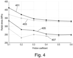
- Figure 4 shows a graphical plot of the results of a finite element method (FEM) calculation of the radial stress generated within the stacks of HTS tapes 201A-F when the tokamak is operated with a current of 28 MA passing through the central column 101.
- FEM finite element method
- plotted results show the radial stress in MPa (vertical, Y axis) in the coils as a function of the friction coefficient (horizontal, X axis) between the outer face of the wedge members 301A-B and the corresponding sidewalls of the channel 115.
- the two uppermost sets of data points 401, 403 indicate the calculated radial stress in the outer stacks 201A, F for wedge angles of 1 degrees and 5 degrees respectively (the same wedge angle being used for each wedge member 301A-D). These results show that the radial stress is lower for the larger wedge angle and that for both angles, increasing the friction coefficient reduces the radial stress monotonically by progressively smaller amounts. Similar results (not shown) are obtained for other angles in the range from 1 degrees to 5 degrees, with the calculated radial stresses having values that are intermediate between the radial stresses for the sets of data points 401, 403. Angles greater than 5 degrees can also be used, e.g. angles up to any one of 10 degrees, 30 degrees, 45 degrees or 60 degrees. Depending on the desired radial stress, the friction coefficient may be varied from 0.1 to 0.3, or from 0.2 to 0.4, or greater than 0.4, e.g. up to 1.0.
- the two lowermost sets of data points 405, 407 indicate the calculated radial stress in the inner stacks 201B-E for wedge angles of 1 degrees and 3 degrees respectively (the same wedge angle being used for each wedge member 301A-D).
- the calculated radial stress decreases monotonically with increasing friction coefficient for the wedge angle of 1 degrees (data points 405), but reaches a minimum value at a friction coefficient of 0.2 for the wedge angle of 3 degrees.
- Calculations of the radial stress for wedge angles of 2, 4 and 5 degrees provide values that are generally between the values obtained for wedge angles of 1 and 3 degrees.
- a target maximum radial stress of 350 MPa in the outer stacks of HTS tape 201A,F can be achieved using a friction coefficient of 0.3 and wedge angles greater than 1 degree.
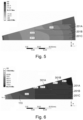
- Figures 5 and 6 show contour plots of the calculated radial stress and the calculated Von Mises stress within an axial cross section of the central column 300, calculated for a wedge angle of 3 degrees and a friction coefficient of 0.3. The calculation is performed for one half of the angular segment shown in Figure 3 for computational efficiency, with boundary conditions applied to enforce the symmetry of the FEM solution with respect to the symmetry of the central column 300.
- the radial stress within the stacks of HTS tapes 107 is calculated to be less than 400 MPa.
- the maximum values of the radial stress for each of the stacks of HTS tape 201A-C are located at the radially innermost faces of the stacks with calculated values of 272.4 MPa for stack 201A, 313.43 MPa for stack 201B and 327.51 MPa for stack 201C.
- the calculated Von Mises stress in the support member 113 is mostly below about 240 MPa adjacent to the wedge members 301A, B. This is sufficiently low that optionally cooling holes can be provided in this part of the central column 300, i.e. between the channels 115 and extending parallel to the axis A-A', without weakening the central column excessively.
- HTS tapes may be "potted", e.g. by encasing the stack of HTS tapes in solder.
- the present disclosure is exemplified by a central column for a toroidal field coil (such as for a tokamak plasma chamber), that many other applications are possible that do not involve toroidal field coils.
- the electromagnets may be used in aerospace applications, included in aircraft, unmanned aerial vehicles, satellites, spacecraft, rocket-propelled vehicles and autonomous exploration vehicles.
- the use of wedged surfaces/wedged members described above may be used generally to reduce (or at least redistribute) the stress on an electrical conductor forced against a support member.
- Such use of wedged surfaces/wedged members is particularly beneficial for superconductor (LTS and/or HTS) materials that degrade or work less efficiently at stresses above a threshold.
Landscapes
- Engineering & Computer Science (AREA)
- Power Engineering (AREA)
- Superconductors And Manufacturing Methods Therefor (AREA)
- Physics & Mathematics (AREA)
- Plasma & Fusion (AREA)
- General Engineering & Computer Science (AREA)
- High Energy & Nuclear Physics (AREA)
Description
- The present invention relates to electromagnets comprising superconductor material. In particular, but not exclusively, it relates to electromagnets for use in plasma chambers, such as those used in tokamak fusion reactors, e.g. electromagnets used in a central column of a toroidal field coil for a tokamak plasma chamber.
- A tokamak features a combination of strong toroidal magnetic field, high plasma current and, usually, a large plasma volume and significant auxiliary heating, to provide hot, stable plasma. This allows tokamaks to generate conditions so that fusion can occur. The auxiliary heating (for example via tens of megawatts of neutral beam injection of high energy H, D or T) is necessary to increase the temperature to the sufficiently high values required for nuclear fusion to occur, and/or to maintain the plasma current.
- A problem is that, because of the large size, large magnetic fields, and high plasma currents generally required, build costs and running costs are high and the engineering has to be robust to cope with the large stored energies present, both in the magnet systems and in the plasma, which has a risk of 'disrupting' - mega-ampere currents reducing to zero in a few thousandths of a second in a violent instability.
- The situation can be improved by contracting the donut-shaped torus of a conventional tokamak to its limit, having the appearance of a cored apple - the 'spherical' tokamak (ST). The first realisation of this concept in the START tokamak at Culham, UK demonstrated a huge increase in efficiency - the magnetic field required to contain a hot plasma can be reduced by a factor of 10. In addition, plasma stability is improved, and building costs reduced.
- To obtain the fusion reactions required for economic power generation (i.e. much more power out than power in), a conventional tokamak would have to be huge so that the energy confinement time (which is roughly proportional to plasma volume) can be large enough that the plasma can be hot enough for thermal fusion to occur.
-
WO 2013/030554 describes an alternative approach, involving the use of a compact spherical tokamak for use as a neutron source or energy source. The low aspect ratio plasma shape in a spherical tokamak improves the particle confinement time and allows net power generation in a much smaller machine. However, a small diameter central column is a necessity, which presents challenges for design of the plasma confinement vessel and associated magnets. - The magnet coils on a tokamak can be divided into two groups. The poloidal field coils are horizontal circular coils wound with their centre lying on the central column of the tokamak, and produce a poloidal field (i.e. one which is substantially parallel to the central column). The toroidal field coils are wound vertically through the central column, and around the outside of the plasma chamber (the "return limbs") to produce a toroidal field (i.e. one which is circular around the central column). The combination of the poloidal and toroidal fields produces a helical field within the plasma chamber which keeps the plasma confined.
- The electrical currents required in the toroidal field are very large. For a compact spherical tokamak, the central column should be as small in diameter as possible. This presents conflicting requirements, as the current density that can be achieved, even with superconducting materials, is limited.
- The large electrical currents, in combination with the large magnetic fields in a tokamak generate large Lorentz forces that may deform or otherwise damage parts of the tokamak.
- Superconducting materials are typically divided into "high temperature superconductors" (HTS) and "low temperature superconductors" (LTS). LTS materials, such as Nb and NbTi, are metals or metal alloys whose superconductivity can be described by BCS theory. All low temperature superconductors have a critical temperature (the temperature above which the material cannot be superconducting even in zero magnetic field) below about 30K. The behaviour of HTS material is not described by BCS theory, and such materials may have critical temperatures above about 30K (though it should be noted that it is the physical differences in superconducting operation and composition, rather than the critical temperature, which define HTS and LTS material). The most commonly used HTS are "cuprate superconductors" - ceramics based on cuprates (compounds containing a copper oxide group), such as BSCCO, or ReBCO (where Re is a rare earth element, commonly Y or Gd). Other HTS materials include iron pnictides (e.g. FeAs and FeSe) and magnesium diboride (MgB2).
- ReBCO is typically manufactured as tapes, which are generally approximately 100 microns thick, and include a substrate (typically electropolished hastelloy approximately 50 microns thick), on which is deposited by IBAD, magnetron sputtering, or another suitable technique a series of buffer layers known as the buffer stack of approximate thickness 0.2 microns. An epitaxial ReBCO-HTS layer (deposited by MOCVD or another suitable technique) overlays the buffer stack, and is typically 1 micron thick. A 1-2 micron silver layer is deposited on the HTS layer by sputtering or another suitable technique, and a copper stabilizer layer is deposited on the tape by electroplating or another suitable technique, which often completely encapsulates the tape.
- The substrate provides a mechanical backbone that can be fed through the manufacturing line and permit growth of subsequent layers. The buffer stack is required to provide a biaxially textured crystalline template upon which to grow the HTS layer, and prevents chemical diffusion of elements from the substrate to the HTS which damage its superconducting properties. The silver layer is required to provide a low resistance interface from the ReBCO to the stabiliser layer, and the
stabiliser layer 105 provides an alternative current path in the event that any part of the ReBCO ceases superconducting (enters the "normal" state). - Commercially available HTS tapes start to degrade at internal stresses larger than about 400 MPa.
- It is an object of the present invention to provide a central column for a toroidal field coil that addresses, or at least alleviates, the problems described above.
- According to a first aspect of the present invention there is provided an electromagnet comprising one or more channels. Each channel has provided therein a conductor element comprising one or more layers of superconductor material for conducting electrical current along an axis of the channel. The conductor element is arranged to contact sidewalls of the channel through respective first and second wedge surfaces that are inclined with respect to one another such that a force biasing the conductor element in a direction perpendicular to the axis (e.g. into the channel) generates opposing contact forces on the first and second wedge surfaces that act to compress the conductor element along a direction with a component perpendicular to the force.
- The electromagnet may be configured so that stress generated during operation of the electromagnet does not exceed a threshold stress associated with the superconductor material. The threshold stress may be, for example, determined based on a degradation of the HTS material and/or a degradation of the HTS material's ability to function as a superconductor.
- The or each channel may be an "open" channel such that the conductor element is not encircled by the walls of the channel. Alternatively, the channel may be "closed", such the walls of the channel surround the conductor element, e.g. the channel may be a through hole in the support member.
- In some cases, the electromagnet may have a central axis, with the axes of the one or more channels being arranged parallel to the central axis. In this case, the one or more layers of superconductor material are arranged to conduct electrical current parallel to the central axis. The force biasing the conductor element in a direction perpendicular to the axis may be directed towards the central axis.
- Each conductor element may comprise one or more stacks of High Temperature Superconductor, HTS, tapes, each HTS tape including a layer of HTS material extending along the channel. The HTS material may be ReBCO.
- Each conductor element may comprise a first wedge member provided between the stack of HTS tapes and the first sidewall of the channel, the first wedge surface being provided on the first wedge member. The first wedge member may be fixed to the stack of HTS tapes.
- The first wedge member may comprise a surface in contact with the stack that is substantially perpendicular to the layers of HTS material.
- For one or more of the conductor elements, an acute angle between the first wedge surface and the surface in contact with the stack may be greater than 1 degree, greater than 3 degrees, or greater than 5 degrees.
- Each conductor element may comprise a second wedge member provided between the one or more stacks of HTS tapes and the second sidewall of the channel, the second wedge surface being provided on the second wedge member.
- A static friction coefficient between each of the wedge surfaces of the conductor element and the respective sidewalls of the channel may be from 0.1 to 0.3, or greater than 0.3, or greater than 0.4.
- Each of the conductor elements may be potted.
- The electromagnet may further comprise a support member, the channels being provided in the support member. The support member may comprise one or more through holes extending in a direction having a component parallel to one or more of the channels. The one or more through holes may be located adjacent to one or more of the sidewalls of the channel. The one or more through holes may be used for cooling the electromagnet.
- According to a second aspect of the present invention there is provided a central column for a toroidal field coil of a tokamak plasma chamber. The central column comprises a plurality of electromagnets according to the first aspect of the present invention. The channels are spaced around a central axis and the one or more layers of superconductor material are arranged for conducting electrical current parallel to the central axis. The force is a radial force biasing the conductor element towards the central axis.
- The channels may be provided in a single support member.
- The central column may comprise one or more holes through the or each support member, each hole extending parallel to the central axis. The one or more holes may be located radially outwards of a radially inner edge of the conductor element. The holes may be used for cooling the central column, e.g. by flowing a cooling fluid through the holes. Despite the one or more holes, the toroidal field coil(s) may be operated without causing the central column to deform as a result of lower internal stresses in the central column compared to known designs of central columns.
- The or each support member may comprise one or more removable angular segments, each angular segment comprising one or more of the plurality of channels.
- Also described herein as an example a toroidal field coil for a tokamak, the toroidal field coil comprising a central column according to the second aspect Also described herein is a tokamak comprising the toroidal field coil.
-
-
Figure 1A is a schematic cross section view of a tokamak; -
Figure 1B is a schematic axial cross section view of the central column of the tokamak ofFigure 1 ; -
Figure 2 is a schematic axial cross section view of an angular segment of a central column of a toroidal field coil; -
Figure 3 is a schematic axial cross section view of a part of an angular segment of a central column of a toroidal field coil according to the present invention; -
Figure 4 is a graphical plot of the results of a Finite Element Method (FEM) calculation of the radial stress (normal stress) for different wedge angles and friction coefficients; -
Figure 5 is a contour plot showing the stress obtained from the FEM calculation; and -
Figure 6 is a contour plot of the von-Mises stress calculated from the FEM calculation. -
Figure 1A shows a vertical cross section through aspherical tokamak 100 comprising toroidal field coils 101, poloidal field coils 103 and atoroidal plasma chamber 105 located within the toroidal field coils 101. Thetokamak 100 also comprises acentral column 107, which extends through the centres of theplasma chamber 105 and the toroidal 101 and poloidal 103 field coils. Each of the toroidal field coils 101 comprises astraight section 109 that extends along the axis A-A' of thecentral column 107 and acurved section 111 that is electrically connected to either end of thestraight section 109 to form a closed loop. -
Figure 1B shows an axial cross section of thecentral column 107 viewed looking along the axis A-A'. Thetokamak 100 in this example comprises 12 toroidal field coils 101 and the respectivestraight portions 109 of each of the toroidal field coils 101 are angularly spaced about the axis A-A' of thecentral column 107 in an equiangular arrangement. The central column comprises asupport member 113 made from copper (although other metals and/or alloys can be used) that extends along the axis A-A' and which has a plurality ofchannels 115 in which thestraight sections 109 of the toroidal field coils 111 are housed. Thestraight portions 109 each comprise a stacked arrangement of lengths of HTS tape extending along thecentral column 107 and are arranged to contact one another through their respective faces. The HTS layers of the tapes run parallel to the axis A-A'. -
Figure 2 is an axial cross section of an angular segment of thecentral column 107 showing one of thestraight portions 109 of one of the toroidal field coils 101. In this example, thestraight portion 109 comprises six stacks of HTS tapes 201 A-F with fourinner stacks 201B-E having the same thickness as one another (i.e. the same length in a direction along a radial line B-B' of thecentral column 107 which passes through the centre of thestraight portion 109 and is transverse to the tapes) provided between twoouter stacks 201A, F, which each have a smaller thickness than theinner stacks 201B-F. The stacks 201A-F are bonded to one another with their radially outermost edges aligned. Eachchannel 115 has a cross sectional profile that corresponds to the outline (i.e. the shape of the perimeter in the cross-section of thechannel 115 perpendicular to line A-A') of the correspondingstraight section 109 of thetoroidal field coil 101. - In use, the stacks of
HTS tape 201A-F carry axial electrical current in an azimuthal magnetic field, and hence experience aLorentz force 203 acting towards the centre of the column 107 (i.e. along the radial direction indicated by the broken line B-B'). These Lorentz forces act radially on theHTS tapes 201A-F to compress them against thesupport member 113 of thecentral column 107, thereby creatingcontact forces 205 between the radially innermost edges of the stacks ofHTS tape 201A-F and the walls of thechannel 115. The combination of theLorentz force 203 and thecontact forces 205 therefore generates compressive stress within theHTS tape 201A-F that may damage theHTS tapes 201A-F or otherwise decrease their ability to carry large electrical currents. -
Figure 3 is similar toFigure 2 except that is shows acentral column 300 in whichwedge members 301A-D are fixed to the outermost faces of thestacks 201A, B, 201E, 201F, to form circumferentially-outer portions of thestraight portions 109 of the toroidal field coils 101. Thechannels 115 through thesupport member 113 are enlarged to accommodate the increased size of thestraight portions 109. Thewedge members 301A-D in this example are triangular prisms that extend with translational symmetry parallel to the axis A-A'. The triangles which form the cross-section of the wedge members may be substantially right angled triangles, and the wedge members may be arranged such that the largest, outer face of the each prism (i.e. the hypotenuse of the triangular cross-section) is directed away from theHTS tapes 201A-F, with the narrower (pointed) end of the prism being located radially inwards of the wider end of the prism (i.e. the side of the triangle furthest from the most acute angle of the triangle). That is, thewedge members 301A-D taper radially inwardly along direction B-B'. Each of thechannels 115 also tapers radially inwardly so that the sidewalls of thechannel 115 are parallel to the corresponding outer faces of thewedge members 301A-D. Indeed the sidewalls of thechannel 115 lie against the corresponding outer faces of thewedge members 301A-D. In this example, the wedge angle 305 (the interior angle between the two largest faces of thewedge member 301A-D, at the narrower end of the prism) is 5 degrees. - In use, the
Lorentz force 203 acting radially on thestraight section 109 of theHTS tapes 201A-F generatescontact forces 303 between the outer face of thewedge members 301A-D and the sidewalls of thechannel 115. The contact forces 303 are oriented normal to the outer face of thewedge members 301A-D, i.e. thecontact forces 303 have a radial component (directed along the radial axis B-B') and a circumferential component (directed towards the radial axis B-B'). Thewedge members 301A-D therefore provide a mechanism whereby radial stress within thecentral column 101 is exchanged for hoop stress, i.e. the radial stress within central column is decreased while the hoop stress increases. This trade-off allows the stacks ofHTS tapes 201A-F to conduct higher currents without causing mechanical damage to the HTS tape. -
Figure 4 shows a graphical plot of the results of a finite element method (FEM) calculation of the radial stress generated within the stacks ofHTS tapes 201A-F when the tokamak is operated with a current of 28 MA passing through thecentral column 101. This current leads to a peak magnetic field of 26.9 T at the radially outermost edges of theHTS tapes 201A-F. The magnetic field decays monotonically away from thecentral column 101 and has a magnitude of 4 T at a distance of 1.4 m from thecentral column 101. The plotted results show the radial stress in MPa (vertical, Y axis) in the coils as a function of the friction coefficient (horizontal, X axis) between the outer face of thewedge members 301A-B and the corresponding sidewalls of thechannel 115. - The two uppermost sets of
data points 401, 403 (shown as filled circles) indicate the calculated radial stress in theouter stacks 201A, F for wedge angles of 1 degrees and 5 degrees respectively (the same wedge angle being used for eachwedge member 301A-D). These results show that the radial stress is lower for the larger wedge angle and that for both angles, increasing the friction coefficient reduces the radial stress monotonically by progressively smaller amounts. Similar results (not shown) are obtained for other angles in the range from 1 degrees to 5 degrees, with the calculated radial stresses having values that are intermediate between the radial stresses for the sets ofdata points - The two lowermost sets of
data points 405, 407 (shown as filled triangles) indicate the calculated radial stress in theinner stacks 201B-E for wedge angles of 1 degrees and 3 degrees respectively (the same wedge angle being used for eachwedge member 301A-D). The calculated radial stress decreases monotonically with increasing friction coefficient for the wedge angle of 1 degrees (data points 405), but reaches a minimum value at a friction coefficient of 0.2 for the wedge angle of 3 degrees. Calculations of the radial stress for wedge angles of 2, 4 and 5 degrees provide values that are generally between the values obtained for wedge angles of 1 and 3 degrees. - A target maximum radial stress of 350 MPa in the outer stacks of
HTS tape 201A,F can be achieved using a friction coefficient of 0.3 and wedge angles greater than 1 degree. -
Figures 5 and 6 show contour plots of the calculated radial stress and the calculated Von Mises stress within an axial cross section of thecentral column 300, calculated for a wedge angle of 3 degrees and a friction coefficient of 0.3. The calculation is performed for one half of the angular segment shown inFigure 3 for computational efficiency, with boundary conditions applied to enforce the symmetry of the FEM solution with respect to the symmetry of thecentral column 300. - The radial stress within the stacks of
HTS tapes 107 is calculated to be less than 400 MPa. The maximum values of the radial stress for each of the stacks ofHTS tape 201A-C are located at the radially innermost faces of the stacks with calculated values of 272.4 MPa forstack 201A, 313.43 MPa forstack 201B and 327.51 MPa forstack 201C. - The calculated Von Mises stress in the
support member 113 is mostly below about 240 MPa adjacent to thewedge members 301A, B. This is sufficiently low that optionally cooling holes can be provided in this part of thecentral column 300, i.e. between thechannels 115 and extending parallel to the axis A-A', without weakening the central column excessively. - Although the above description has focussed on a central column comprising HTS tape, other forms of HTS material such as wires can also be used or LTS materials can be used instead of, or as well as, HTS material. The HTS tapes may be "potted", e.g. by encasing the stack of HTS tapes in solder.
- Although the present disclosure is exemplified by a central column for a toroidal field coil (such as for a tokamak plasma chamber), that many other applications are possible that do not involve toroidal field coils. For example, the electromagnets may be used in aerospace applications, included in aircraft, unmanned aerial vehicles, satellites, spacecraft, rocket-propelled vehicles and autonomous exploration vehicles. Indeed, it will be appreciated that the use of wedged surfaces/wedged members described above may be used generally to reduce (or at least redistribute) the stress on an electrical conductor forced against a support member. Such use of wedged surfaces/wedged members is particularly beneficial for superconductor (LTS and/or HTS) materials that degrade or work less efficiently at stresses above a threshold.
Claims (15)
- An electromagnet comprising one or more channels (115), each channel having provided therein a conductor element (109) comprising one or more layers of superconductor material for conducting electrical current along an axis (A-A') of the channel, the conductor element being arranged to contact sidewalls of the channel through respective first and second wedge surfaces that are inclined with respect to one another such that a force (203) biasing the conductor element in a direction (B-B') perpendicular to the axis (A-A') generates opposing contact forces (303) on the first and second wedge surfaces that act to compress the conductor element along a direction with a component perpendicular to the force.
- An electromagnet according to claim 1, wherein each conductor element (109) comprises one or more stacks of High Temperature Superconductor, HTS, tapes (201A-F), each HTS tape including a layer of HTS material extending along the axis (A-A') of the channel (109).
- An electromagnet according to claim 2, wherein each conductor element (109) comprises a first wedge member (301A-D) provided between the stack of HTS tapes (201A-F) and one of the sidewalls of the channel, the first wedge surface being provided on the first wedge member.
- An electromagnet according to claim 3, wherein the first wedge member (301A-D) is fixed to the stack of HTS tapes (201A-F).
- An electromagnet according to claim 3 or 4, wherein the first wedge member (301A-D) comprises a surface in contact with the stack (201A-F) that is substantially perpendicular to the layers of HTS material.
- An electromagnet according to claim 5, wherein, for one or more of the conductor elements (109), an acute angle between the first wedge surface (301A,B) and the surface in contact with the stack is greater than 1 degree, greater than 3 degrees, or greater than 5 degrees.
- An electromagnet according to claim 6, wherein each conductor element (109) comprises a second wedge member (301A-D) provided between the stack of HTS tapes (201A-F) and another sidewall of the channel, the second wedge surface being provided on the second wedge member.
- An electromagnet according to any one of the preceding claims, wherein a static friction coefficient between each of the wedge surfaces of the conductor element (109) and the respective sidewall of the channel (115) is from 0.1 to 0.3, or greater than 0.3, or greater than 0.4.
- An electromagnet according to any one of the preceding claims, wherein each of the conductor elements (109) is potted.
- An electromagnet according to any one of the preceding claims, further comprising a support member, the channels (115) being provided in the support member, the support member comprising one or more through holes extending in a direction having a component parallel to one or more of the channels, and, optionally, wherein the one or more holes are located adjacent one or more of the sidewalls of the channel.
- A central column (107) for a toroidal field coil (101) of a tokamak plasma chamber (100), the central column comprising a plurality of electromagnets according to any one of the preceding claims, the channels (115) being spaced around a central axis (A-A') and the one or more layers of superconductor material being arranged for conducting electrical current parallel to the central axis, wherein the force (203) is a radial force biasing the conductor element (109) towards the central axis.
- A central column according to clam 11, wherein the channels (115) are provided in a single support member (113).
- A central column according to claim 11 or 12, comprising one or more holes through the or each support member (113), each hole extending parallel to the central axis (A-A').
- A central column according to claim 13, wherein the one or more holes are located radially outwards of a radially inner edge of the conductor element (109).
- A central column according to any one of claims 11 to 14, wherein the or each support member (113) comprises one or more removable angular segments, each angular segment comprising one or more of the plurality of channels (115).
Applications Claiming Priority (2)
| Application Number | Priority Date | Filing Date | Title |
|---|---|---|---|
| GBGB2007245.0A GB202007245D0 (en) | 2020-05-15 | 2020-05-15 | Central column of a toroidal field coil |
| PCT/EP2021/062844 WO2021229062A1 (en) | 2020-05-15 | 2021-05-14 | Superconductor electromagnet |
Publications (2)
| Publication Number | Publication Date |
|---|---|
| EP4150650A1 EP4150650A1 (en) | 2023-03-22 |
| EP4150650B1 true EP4150650B1 (en) | 2024-11-20 |
Family
ID=71135338
Family Applications (1)
| Application Number | Title | Priority Date | Filing Date |
|---|---|---|---|
| EP21726631.1A Active EP4150650B1 (en) | 2020-05-15 | 2021-05-14 | Superconductor electromagnet |
Country Status (9)
| Country | Link |
|---|---|
| US (1) | US20230307149A1 (en) |
| EP (1) | EP4150650B1 (en) |
| JP (1) | JP7750868B2 (en) |
| KR (1) | KR102868004B1 (en) |
| CN (1) | CN115605967A (en) |
| AU (1) | AU2021272715B2 (en) |
| CA (1) | CA3177960A1 (en) |
| GB (1) | GB202007245D0 (en) |
| WO (1) | WO2021229062A1 (en) |
Families Citing this family (4)
| Publication number | Priority date | Publication date | Assignee | Title |
|---|---|---|---|---|
| CN113936815B (en) * | 2020-07-14 | 2023-11-17 | 新奥科技发展有限公司 | Circumferential field coil and fusion device |
| CN113936816B (en) * | 2020-07-14 | 2023-11-17 | 新奥科技发展有限公司 | Toroidal field coils and fusion devices |
| CN118335444B (en) * | 2024-06-12 | 2024-08-23 | 中国科学院合肥物质科学研究院 | Shearing resistant structure for fusion reactor circumferential field magnet |
| CN118380168B (en) * | 2024-06-25 | 2024-09-06 | 中国科学院合肥物质科学研究院 | A Neutral Beam Injection Power Feedback Control Method |
Family Cites Families (17)
| Publication number | Priority date | Publication date | Assignee | Title |
|---|---|---|---|---|
| JPS607369B2 (en) * | 1979-06-07 | 1985-02-23 | 三菱電機株式会社 | superconducting coil |
| JPS5673896A (en) * | 1979-11-16 | 1981-06-18 | Hitachi Ltd | Toroidal nuclear fusion reactor |
| US4330726A (en) | 1980-12-04 | 1982-05-18 | General Electric Company | Air-gap winding stator construction for dynamoelectric machine |
| JPS57106008A (en) * | 1980-12-23 | 1982-07-01 | Toshiba Corp | Superconducting toroidal coil |
| JPS58204411A (en) * | 1982-05-24 | 1983-11-29 | 株式会社東芝 | Electric machine insulating conductor |
| JPS62262311A (en) * | 1986-05-08 | 1987-11-14 | 古河電気工業株式会社 | Superconductor wire |
| JPH07110129B2 (en) * | 1989-02-16 | 1995-11-22 | 工業技術院長 | Stator winding of superconducting generator |
| JP5364356B2 (en) | 2008-12-11 | 2013-12-11 | 三菱重工業株式会社 | Superconducting coil device |
| US10269458B2 (en) * | 2010-08-05 | 2019-04-23 | Alpha Ring International, Ltd. | Reactor using electrical and magnetic fields |
| JP5062263B2 (en) * | 2010-01-08 | 2012-10-31 | 住友電気工業株式会社 | Superconducting coil device, superconducting device, and method of manufacturing superconducting coil device |
| US9852816B2 (en) | 2011-09-02 | 2017-12-26 | Tokamak Energy Ltd | Efficient compact fusion reactor |
| US10284029B2 (en) * | 2012-03-20 | 2019-05-07 | Linear Labs, LLC | Brushed electric motor/generator |
| DK177684B1 (en) * | 2012-12-21 | 2014-03-03 | Envision Energy Denmark Aps | Wind turbine having a HTS generator with a plurality of phases |
| US9793036B2 (en) * | 2015-02-13 | 2017-10-17 | Particle Beam Lasers, Inc. | Low temperature superconductor and aligned high temperature superconductor magnetic dipole system and method for producing high magnetic fields |
| US9755463B2 (en) * | 2015-08-11 | 2017-09-05 | Genesis Robotics Llp | Electric machine |
| GB201618333D0 (en) * | 2016-10-31 | 2016-12-14 | Tokamak Energy Ltd | Quench protection in superconducting magnets |
| JP7663842B2 (en) * | 2022-01-20 | 2025-04-17 | 豊田合成株式会社 | Glass Run |
-
2020
- 2020-05-15 GB GBGB2007245.0A patent/GB202007245D0/en not_active Ceased
-
2021
- 2021-05-14 AU AU2021272715A patent/AU2021272715B2/en active Active
- 2021-05-14 CN CN202180034880.2A patent/CN115605967A/en active Pending
- 2021-05-14 JP JP2022568514A patent/JP7750868B2/en active Active
- 2021-05-14 CA CA3177960A patent/CA3177960A1/en active Pending
- 2021-05-14 EP EP21726631.1A patent/EP4150650B1/en active Active
- 2021-05-14 WO PCT/EP2021/062844 patent/WO2021229062A1/en not_active Ceased
- 2021-05-14 KR KR1020227040963A patent/KR102868004B1/en active Active
- 2021-05-14 US US17/998,699 patent/US20230307149A1/en active Pending
Also Published As
| Publication number | Publication date |
|---|---|
| CN115605967A (en) | 2023-01-13 |
| JP7750868B2 (en) | 2025-10-07 |
| GB202007245D0 (en) | 2020-07-01 |
| WO2021229062A1 (en) | 2021-11-18 |
| CA3177960A1 (en) | 2021-11-18 |
| AU2021272715B2 (en) | 2026-04-16 |
| KR20230009402A (en) | 2023-01-17 |
| JP2023525788A (en) | 2023-06-19 |
| EP4150650A1 (en) | 2023-03-22 |
| AU2021272715A1 (en) | 2022-12-08 |
| US20230307149A1 (en) | 2023-09-28 |
| KR102868004B1 (en) | 2025-10-01 |
Similar Documents
| Publication | Publication Date | Title |
|---|---|---|
| AU2021272715B2 (en) | Superconductor electromagnet | |
| US10332640B2 (en) | Toroidal field coil for use in a fusion reactor | |
| EP4147281B1 (en) | A method of manufacturing a high temperature superconductor field coil and a high temperature superconductor field coil | |
| EP3721446B1 (en) | Magnet assembly for a tokamak | |
| KR102878777B1 (en) | Central column for toroidal magnetic field coils in a tokamak plasma chamber | |
| US20210319938A1 (en) | Bent toroidal field coils | |
| RU2833905C1 (en) | Superconducting electromagnet | |
| Ries | Magnet technology and conductor design with high temperature superconductors | |
| RU2833594C2 (en) | Tokamak plasma chamber toroidal field coil central column | |
| JP2021513740A (en) | HTS magnet quench start system | |
| Dolan et al. | Superconducting Magnets | |
| de Rijk | High-field Accelerator Magnets |
Legal Events
| Date | Code | Title | Description |
|---|---|---|---|
| STAA | Information on the status of an ep patent application or granted ep patent |
Free format text: STATUS: UNKNOWN |
|
| STAA | Information on the status of an ep patent application or granted ep patent |
Free format text: STATUS: THE INTERNATIONAL PUBLICATION HAS BEEN MADE |
|
| PUAI | Public reference made under article 153(3) epc to a published international application that has entered the european phase |
Free format text: ORIGINAL CODE: 0009012 |
|
| STAA | Information on the status of an ep patent application or granted ep patent |
Free format text: STATUS: REQUEST FOR EXAMINATION WAS MADE |
|
| 17P | Request for examination filed |
Effective date: 20221122 |
|
| AK | Designated contracting states |
Kind code of ref document: A1 Designated state(s): AL AT BE BG CH CY CZ DE DK EE ES FI FR GB GR HR HU IE IS IT LI LT LU LV MC MK MT NL NO PL PT RO RS SE SI SK SM TR |
|
| P01 | Opt-out of the competence of the unified patent court (upc) registered |
Effective date: 20230512 |
|
| DAV | Request for validation of the european patent (deleted) | ||
| DAX | Request for extension of the european patent (deleted) | ||
| GRAP | Despatch of communication of intention to grant a patent |
Free format text: ORIGINAL CODE: EPIDOSNIGR1 |
|
| STAA | Information on the status of an ep patent application or granted ep patent |
Free format text: STATUS: GRANT OF PATENT IS INTENDED |
|
| INTG | Intention to grant announced |
Effective date: 20240619 |
|
| GRAS | Grant fee paid |
Free format text: ORIGINAL CODE: EPIDOSNIGR3 |
|
| GRAA | (expected) grant |
Free format text: ORIGINAL CODE: 0009210 |
|
| STAA | Information on the status of an ep patent application or granted ep patent |
Free format text: STATUS: THE PATENT HAS BEEN GRANTED |
|
| AK | Designated contracting states |
Kind code of ref document: B1 Designated state(s): AL AT BE BG CH CY CZ DE DK EE ES FI FR GB GR HR HU IE IS IT LI LT LU LV MC MK MT NL NO PL PT RO RS SE SI SK SM TR |
|
| REG | Reference to a national code |
Ref country code: GB Ref legal event code: FG4D |
|
| REG | Reference to a national code |
Ref country code: CH Ref legal event code: EP |
|
| REG | Reference to a national code |
Ref country code: DE Ref legal event code: R096 Ref document number: 602021022095 Country of ref document: DE |
|
| REG | Reference to a national code |
Ref country code: IE Ref legal event code: FG4D |
|
| REG | Reference to a national code |
Ref country code: LT Ref legal event code: MG9D |
|
| REG | Reference to a national code |
Ref country code: NL Ref legal event code: MP Effective date: 20241120 |
|
| PG25 | Lapsed in a contracting state [announced via postgrant information from national office to epo] |
Ref country code: PT Free format text: LAPSE BECAUSE OF FAILURE TO SUBMIT A TRANSLATION OF THE DESCRIPTION OR TO PAY THE FEE WITHIN THE PRESCRIBED TIME-LIMIT Effective date: 20250320 Ref country code: HR Free format text: LAPSE BECAUSE OF FAILURE TO SUBMIT A TRANSLATION OF THE DESCRIPTION OR TO PAY THE FEE WITHIN THE PRESCRIBED TIME-LIMIT Effective date: 20241120 Ref country code: IS Free format text: LAPSE BECAUSE OF FAILURE TO SUBMIT A TRANSLATION OF THE DESCRIPTION OR TO PAY THE FEE WITHIN THE PRESCRIBED TIME-LIMIT Effective date: 20250320 |
|
| PG25 | Lapsed in a contracting state [announced via postgrant information from national office to epo] |
Ref country code: FI Free format text: LAPSE BECAUSE OF FAILURE TO SUBMIT A TRANSLATION OF THE DESCRIPTION OR TO PAY THE FEE WITHIN THE PRESCRIBED TIME-LIMIT Effective date: 20241120 Ref country code: NL Free format text: LAPSE BECAUSE OF FAILURE TO SUBMIT A TRANSLATION OF THE DESCRIPTION OR TO PAY THE FEE WITHIN THE PRESCRIBED TIME-LIMIT Effective date: 20241120 |
|
| REG | Reference to a national code |
Ref country code: AT Ref legal event code: MK05 Ref document number: 1744363 Country of ref document: AT Kind code of ref document: T Effective date: 20241120 |
|
| PG25 | Lapsed in a contracting state [announced via postgrant information from national office to epo] |
Ref country code: BG Free format text: LAPSE BECAUSE OF FAILURE TO SUBMIT A TRANSLATION OF THE DESCRIPTION OR TO PAY THE FEE WITHIN THE PRESCRIBED TIME-LIMIT Effective date: 20241120 |
|
| PG25 | Lapsed in a contracting state [announced via postgrant information from national office to epo] |
Ref country code: ES Free format text: LAPSE BECAUSE OF FAILURE TO SUBMIT A TRANSLATION OF THE DESCRIPTION OR TO PAY THE FEE WITHIN THE PRESCRIBED TIME-LIMIT Effective date: 20241120 |
|
| PG25 | Lapsed in a contracting state [announced via postgrant information from national office to epo] |
Ref country code: NO Free format text: LAPSE BECAUSE OF FAILURE TO SUBMIT A TRANSLATION OF THE DESCRIPTION OR TO PAY THE FEE WITHIN THE PRESCRIBED TIME-LIMIT Effective date: 20250220 |
|
| PG25 | Lapsed in a contracting state [announced via postgrant information from national office to epo] |
Ref country code: AT Free format text: LAPSE BECAUSE OF FAILURE TO SUBMIT A TRANSLATION OF THE DESCRIPTION OR TO PAY THE FEE WITHIN THE PRESCRIBED TIME-LIMIT Effective date: 20241120 Ref country code: GR Free format text: LAPSE BECAUSE OF FAILURE TO SUBMIT A TRANSLATION OF THE DESCRIPTION OR TO PAY THE FEE WITHIN THE PRESCRIBED TIME-LIMIT Effective date: 20250221 Ref country code: LV Free format text: LAPSE BECAUSE OF FAILURE TO SUBMIT A TRANSLATION OF THE DESCRIPTION OR TO PAY THE FEE WITHIN THE PRESCRIBED TIME-LIMIT Effective date: 20241120 |
|
| PG25 | Lapsed in a contracting state [announced via postgrant information from national office to epo] |
Ref country code: PL Free format text: LAPSE BECAUSE OF FAILURE TO SUBMIT A TRANSLATION OF THE DESCRIPTION OR TO PAY THE FEE WITHIN THE PRESCRIBED TIME-LIMIT Effective date: 20241120 |
|
| PG25 | Lapsed in a contracting state [announced via postgrant information from national office to epo] |
Ref country code: RS Free format text: LAPSE BECAUSE OF FAILURE TO SUBMIT A TRANSLATION OF THE DESCRIPTION OR TO PAY THE FEE WITHIN THE PRESCRIBED TIME-LIMIT Effective date: 20250220 |
|
| PG25 | Lapsed in a contracting state [announced via postgrant information from national office to epo] |
Ref country code: SM Free format text: LAPSE BECAUSE OF FAILURE TO SUBMIT A TRANSLATION OF THE DESCRIPTION OR TO PAY THE FEE WITHIN THE PRESCRIBED TIME-LIMIT Effective date: 20241120 |
|
| PGFP | Annual fee paid to national office [announced via postgrant information from national office to epo] |
Ref country code: DE Payment date: 20250521 Year of fee payment: 5 |
|
| PG25 | Lapsed in a contracting state [announced via postgrant information from national office to epo] |
Ref country code: DK Free format text: LAPSE BECAUSE OF FAILURE TO SUBMIT A TRANSLATION OF THE DESCRIPTION OR TO PAY THE FEE WITHIN THE PRESCRIBED TIME-LIMIT Effective date: 20241120 |
|
| PGFP | Annual fee paid to national office [announced via postgrant information from national office to epo] |
Ref country code: GB Payment date: 20250527 Year of fee payment: 5 |
|
| PGFP | Annual fee paid to national office [announced via postgrant information from national office to epo] |
Ref country code: IT Payment date: 20250527 Year of fee payment: 5 |
|
| PG25 | Lapsed in a contracting state [announced via postgrant information from national office to epo] |
Ref country code: EE Free format text: LAPSE BECAUSE OF FAILURE TO SUBMIT A TRANSLATION OF THE DESCRIPTION OR TO PAY THE FEE WITHIN THE PRESCRIBED TIME-LIMIT Effective date: 20241120 |
|
| PGFP | Annual fee paid to national office [announced via postgrant information from national office to epo] |
Ref country code: FR Payment date: 20250528 Year of fee payment: 5 |
|
| PG25 | Lapsed in a contracting state [announced via postgrant information from national office to epo] |
Ref country code: RO Free format text: LAPSE BECAUSE OF FAILURE TO SUBMIT A TRANSLATION OF THE DESCRIPTION OR TO PAY THE FEE WITHIN THE PRESCRIBED TIME-LIMIT Effective date: 20241120 |
|
| PG25 | Lapsed in a contracting state [announced via postgrant information from national office to epo] |
Ref country code: SK Free format text: LAPSE BECAUSE OF FAILURE TO SUBMIT A TRANSLATION OF THE DESCRIPTION OR TO PAY THE FEE WITHIN THE PRESCRIBED TIME-LIMIT Effective date: 20241120 |
|
| PG25 | Lapsed in a contracting state [announced via postgrant information from national office to epo] |
Ref country code: CZ Free format text: LAPSE BECAUSE OF FAILURE TO SUBMIT A TRANSLATION OF THE DESCRIPTION OR TO PAY THE FEE WITHIN THE PRESCRIBED TIME-LIMIT Effective date: 20241120 |
|
| REG | Reference to a national code |
Ref country code: DE Ref legal event code: R097 Ref document number: 602021022095 Country of ref document: DE |
|
| PG25 | Lapsed in a contracting state [announced via postgrant information from national office to epo] |
Ref country code: SE Free format text: LAPSE BECAUSE OF FAILURE TO SUBMIT A TRANSLATION OF THE DESCRIPTION OR TO PAY THE FEE WITHIN THE PRESCRIBED TIME-LIMIT Effective date: 20241120 |
|
| PLBE | No opposition filed within time limit |
Free format text: ORIGINAL CODE: 0009261 |
|
| STAA | Information on the status of an ep patent application or granted ep patent |
Free format text: STATUS: NO OPPOSITION FILED WITHIN TIME LIMIT |
|
| 26N | No opposition filed |
Effective date: 20250821 |
|
| REG | Reference to a national code |
Ref country code: CH Ref legal event code: H13 Free format text: ST27 STATUS EVENT CODE: U-0-0-H10-H13 (AS PROVIDED BY THE NATIONAL OFFICE) Effective date: 20251223 |
|
| PG25 | Lapsed in a contracting state [announced via postgrant information from national office to epo] |
Ref country code: LU Free format text: LAPSE BECAUSE OF NON-PAYMENT OF DUE FEES Effective date: 20250514 |
|
| PG25 | Lapsed in a contracting state [announced via postgrant information from national office to epo] |
Ref country code: CH Free format text: LAPSE BECAUSE OF NON-PAYMENT OF DUE FEES Effective date: 20250531 |
|
| REG | Reference to a national code |
Ref country code: BE Ref legal event code: MM Effective date: 20250531 |
|
| PG25 | Lapsed in a contracting state [announced via postgrant information from national office to epo] |
Ref country code: MC Free format text: LAPSE BECAUSE OF FAILURE TO SUBMIT A TRANSLATION OF THE DESCRIPTION OR TO PAY THE FEE WITHIN THE PRESCRIBED TIME-LIMIT Effective date: 20241120 |
|
| PG25 | Lapsed in a contracting state [announced via postgrant information from national office to epo] |
Ref country code: IE Free format text: LAPSE BECAUSE OF NON-PAYMENT OF DUE FEES Effective date: 20250514 |
|
| PG25 | Lapsed in a contracting state [announced via postgrant information from national office to epo] |
Ref country code: BE Free format text: LAPSE BECAUSE OF NON-PAYMENT OF DUE FEES Effective date: 20250531 |