EP4150207B1 - Kupplungssystem zum verbinden eines gekrümmten gegenstandes mit einer zentralen welle - Google Patents
Kupplungssystem zum verbinden eines gekrümmten gegenstandes mit einer zentralen welle Download PDFInfo
- Publication number
- EP4150207B1 EP4150207B1 EP21804867.6A EP21804867A EP4150207B1 EP 4150207 B1 EP4150207 B1 EP 4150207B1 EP 21804867 A EP21804867 A EP 21804867A EP 4150207 B1 EP4150207 B1 EP 4150207B1
- Authority
- EP
- European Patent Office
- Prior art keywords
- curved object
- curved
- flange portion
- blade
- coupling member
- Prior art date
- Legal status (The legal status is an assumption and is not a legal conclusion. Google has not performed a legal analysis and makes no representation as to the accuracy of the status listed.)
- Active
Links
Images


Classifications
-
- F—MECHANICAL ENGINEERING; LIGHTING; HEATING; WEAPONS; BLASTING
- F03—MACHINES OR ENGINES FOR LIQUIDS; WIND, SPRING, OR WEIGHT MOTORS; PRODUCING MECHANICAL POWER OR A REACTIVE PROPULSIVE THRUST, NOT OTHERWISE PROVIDED FOR
- F03D—WIND MOTORS
- F03D3/00—Wind motors with rotation axis substantially perpendicular to the air flow entering the rotor
- F03D3/06—Rotors
- F03D3/062—Rotors characterised by their construction elements
- F03D3/064—Fixing wind engaging parts to rest of rotor
-
- F—MECHANICAL ENGINEERING; LIGHTING; HEATING; WEAPONS; BLASTING
- F16—ENGINEERING ELEMENTS AND UNITS; GENERAL MEASURES FOR PRODUCING AND MAINTAINING EFFECTIVE FUNCTIONING OF MACHINES OR INSTALLATIONS; THERMAL INSULATION IN GENERAL
- F16B—DEVICES FOR FASTENING OR SECURING CONSTRUCTIONAL ELEMENTS OR MACHINE PARTS TOGETHER, e.g. NAILS, BOLTS, CIRCLIPS, CLAMPS, CLIPS OR WEDGES; JOINTS OR JOINTING
- F16B37/00—Nuts or like thread-engaging members
- F16B37/04—Devices for fastening nuts to surfaces, e.g. sheets, plates
- F16B37/048—Non-releasable devices
-
- F—MECHANICAL ENGINEERING; LIGHTING; HEATING; WEAPONS; BLASTING
- F03—MACHINES OR ENGINES FOR LIQUIDS; WIND, SPRING, OR WEIGHT MOTORS; PRODUCING MECHANICAL POWER OR A REACTIVE PROPULSIVE THRUST, NOT OTHERWISE PROVIDED FOR
- F03D—WIND MOTORS
- F03D3/00—Wind motors with rotation axis substantially perpendicular to the air flow entering the rotor
- F03D3/005—Wind motors with rotation axis substantially perpendicular to the air flow entering the rotor the axis being vertical
- F03D3/009—Wind motors with rotation axis substantially perpendicular to the air flow entering the rotor the axis being vertical of the drag type, e.g. Savonius
-
- F—MECHANICAL ENGINEERING; LIGHTING; HEATING; WEAPONS; BLASTING
- F05—INDEXING SCHEMES RELATING TO ENGINES OR PUMPS IN VARIOUS SUBCLASSES OF CLASSES F01-F04
- F05B—INDEXING SCHEME RELATING TO WIND, SPRING, WEIGHT, INERTIA OR LIKE MOTORS, TO MACHINES OR ENGINES FOR LIQUIDS COVERED BY SUBCLASSES F03B, F03D AND F03G
- F05B2260/00—Function
- F05B2260/30—Retaining components in desired mutual position
- F05B2260/301—Retaining bolts or nuts
-
- Y—GENERAL TAGGING OF NEW TECHNOLOGICAL DEVELOPMENTS; GENERAL TAGGING OF CROSS-SECTIONAL TECHNOLOGIES SPANNING OVER SEVERAL SECTIONS OF THE IPC; TECHNICAL SUBJECTS COVERED BY FORMER USPC CROSS-REFERENCE ART COLLECTIONS [XRACs] AND DIGESTS
- Y02—TECHNOLOGIES OR APPLICATIONS FOR MITIGATION OR ADAPTATION AGAINST CLIMATE CHANGE
- Y02E—REDUCTION OF GREENHOUSE GAS [GHG] EMISSIONS, RELATED TO ENERGY GENERATION, TRANSMISSION OR DISTRIBUTION
- Y02E10/00—Energy generation through renewable energy sources
- Y02E10/70—Wind energy
- Y02E10/72—Wind turbines with rotation axis in wind direction
-
- Y—GENERAL TAGGING OF NEW TECHNOLOGICAL DEVELOPMENTS; GENERAL TAGGING OF CROSS-SECTIONAL TECHNOLOGIES SPANNING OVER SEVERAL SECTIONS OF THE IPC; TECHNICAL SUBJECTS COVERED BY FORMER USPC CROSS-REFERENCE ART COLLECTIONS [XRACs] AND DIGESTS
- Y02—TECHNOLOGIES OR APPLICATIONS FOR MITIGATION OR ADAPTATION AGAINST CLIMATE CHANGE
- Y02E—REDUCTION OF GREENHOUSE GAS [GHG] EMISSIONS, RELATED TO ENERGY GENERATION, TRANSMISSION OR DISTRIBUTION
- Y02E10/00—Energy generation through renewable energy sources
- Y02E10/70—Wind energy
- Y02E10/74—Wind turbines with rotation axis perpendicular to the wind direction
Definitions
- the present invention relates to solving the problem of attaching a curved structure, usually but not necessarily made of plastic or composites, to another curved structure, in the usual embodiment a shaft.
- a curved structure usually but not necessarily made of plastic or composites
- the main application foreseen here is to small wind turbines but it applies to other combinations of curved structures.
- the present invention successfully addresses the shortcomings of the presently known configurations by providing a better connection between the shaft and the curved structure.
- a coupling system for coupling a curved object to a central shaft the curved object includes an inner surface facing the central shaft and an outer surface, the system comprising:
- the coupling member is a rod coupled on a first end thereof to the central shaft and on a second end thereof to the curved object.
- the fastening member includes a least one washer and a nut and wherein the flat portion is configured to allow the washer and the nut to rest on the flat portion.
- the first section of the flange portion includes a curvature which includes aerodynamic properties configured to conform with the aerodynamic properties of the curved surface.
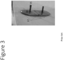
- Figures 1-3 illustrate problematic products based on current art.
- FIG. 3 is a prior art example of this where bolts are placed from a strut (also called an arm or flange) using bolts from the inside into unequal thick areas of the blades. This makes sense for certain small turbines but tends to be bulkier and take up more space. They may also involve more labor, for example, to connect fiberglass to the inside of the blades.
- Figure 1 shows that solution, simply attaching a rod, washer, and nut (2) at right angles to the curved blades (1).
- the result of this mismatch between the straight perpendicular force of the rod and its attachments with curved blades can result in folds (3) that break the blades, usually within a few years. We bought one of these to verify the poor design.
- Figure 2 shows another prior art solution.
- a straight interface (12) is depressed from the blade surface, probably made in a mold, which enables the rods and nuts (11) to connect in such a way that no folds are created.
- a rod is not necessarily cylindrical in shape.
- the disadvantage here is that it creates weak spots in the blades because an area of decreased thickness is adjacent to a thicker area. It is well known that a consistent and adequate thickness helps resist high forces from high winds so the blade doesn't break from the stress on the areas of lesser thickness, and the connection is always a location of high stress. However, this general principle has generally been ignored for the sake of convenient attachment.
- the applicant proposes a novel approach that maintains the thickness of the blades at the connection interface and provides a perpendicular surface for the rod or other connecting piece attachment, thereby addressing the deficiencies of the current methods of using rods. They also are present on the outside and inside of the blade.
- the innovation consists of a combination of features, of which the prior art may have made use of less than the full solution:
- FIG 4 shows the blade (21) in cross-section.
- the blade has an inner (28) and outer surface (29).
- fastening member in this case, washers (25, 26), and nut (27) that connect the blade to the shaft via the coupling member (24).
- (26) is a washer which fills the pocket, which is seen as a depression in the outer surface of the blade and extends from the flange portion of 22 to 23. Then the blade forms an inner nubbin or protrusion (where 20 meets 23) that slightly bulges to the inside of the blade so that the remainder of the blade resumes the curvature of the surrounding blade without sacrificing the thickness and strength of the blade.
- (22) is approximately the same thickness as (23), and at (23) the blades resume a similar curvature to what it had at (21).
- (22) and (23) together form a base for the washers and rod to attach inside a pocket. Note that in this embodiment, the outer and inner nubbins are approximately balanced.
- a mold for use with plastic and composites is the ideal way to make this blade and interface.
- a mold with the characteristics described is also included in the invention.
- Figure 5 is a different view of and a cross-section of the blade immediately adjacent to the interface changes shown in Figure 4 .
- the blade (31) adjacent to the rod (35) and outer and inner protrusions (32, 33) is completely smooth and continuous without any folds or changes in thickness.
- the outer protrusion (32) deflects the oncoming air, which provides resistance to the revolution of the leading edge of the blade, over the nut (34) so there is minimal aerodynamic interference from the nut sticking out.
- Figure 6 shows how it is implemented on blades produced by the applicant's team.
- the blade (41) has rods and nubbins (42) that attach to and pass through a central shaft (43).
- Figure 10 is a drawing of the pocket from the inside.
- Figure 11 is a drawing of the pocket from the outside. Part of what one should pay attention to is the base for the rod that is perpendicular to the shaft.
- the novel shape of the blade with the nubbins can be produced by making a mold with these features.
- the result is a more durable, low-cost, and easy to assemble set of turbine blades.
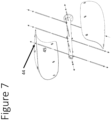
- the rod (or coupling member) is not necessarily a single piece. It can comprise a group of pieces that make up the rod, as in the exploded view of Figure 7 , for a turbine with two blades and the rod (45) passing through a hole (44) in the shaft.
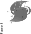
- Figure 8 is a three-dimensional view of how the whole turbine of Figure 6 and 7 would look.
- the turbine includes a shaft (47), and a blade (41) which is coupled to the shaft by a coupling member (45) and a fastening member (46).
- Figure 9 gives another view of a shaft (47), a coupling member (45) and a fastening member (46).
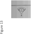
- Figure 11 also shows the big picture with a section of a turbine and its blade.
- (50) is the blade
- (51) is the shaft
- (52) is the fastening member
- the head of the bighead inserted into a pocket in the blade
- (53) is the coupling member or truss.
- additional fastening members would be any additional screws or washers required to attach the coupling member to the fastening members.
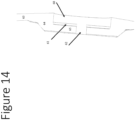
- FIG 14 is a cross section of the blade (63).
- (60) is the pocket.
- the pocket (60) is a depression in the outer curvature of the blade.
- (61) is the base of the pocket.
- (62) is the hole or aperture for the bighead (which in this case is the "coupling member") to extend inwards towards the shaft, on the way attaching to a fastening member.
- the area surrounding the bighead hole has the equivalent thickness of the blade and is smooth and continuous with the rest of the blade.
- (64) is the flange portion between the blade (63) and the base (65). It is noteworthy that the angle of the blade (63) resumes its curve after the intervening pocket.
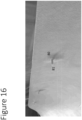
- Figure 16 shows the invention in a fiberglass blade where the flange portion protrudes from the inner surface of the curved object and wherein said flat portion extends outside said inner surface.
- (81) is the shaft of the bighead.
- (80) is the protrusion of the flange portion.
- the base of the bighead is not seen because it is buried in the pocket and covered by the flange portion.
- (80) is the same as Figure 13 , (56).
- the new art in Figure 16 is much less obtrusive, much stronger, and smoother aerodynamically.
Landscapes
- Engineering & Computer Science (AREA)
- General Engineering & Computer Science (AREA)
- Mechanical Engineering (AREA)
- Life Sciences & Earth Sciences (AREA)
- Sustainable Development (AREA)
- Sustainable Energy (AREA)
- Chemical & Material Sciences (AREA)
- Combustion & Propulsion (AREA)
- Connection Of Plates (AREA)
- Wind Motors (AREA)
Claims (9)
- Ein Kupplungssystem zum Verbinden eines gekrümmten Gegenstandes (21, 31, 41, 50, 63) mit einer zentralen Welle (43, 47, 51); der gekrümmte Gegenstand schließt eine innere Oberfläche (28) ein, die der zentralen Welle (43) zugewandt ist, und eine äußere Oberfläche (29), die in die entgegengesetzte Richtung weist; wobei das System Folgendes umfasst:- ein Kupplungsglied (24), angeordnet zum Verbinden des gekrümmten Gegenstands (21, 31, 41, 50, 63) mit der zentralen Welle (43, 47, 51);- mindestens eine Tasche (44, 54, 60), integral geformt auf einer gekrümmten Oberfläche des gekrümmten Gegenstands (21, 31, 41, 50, 63) und bestimmt als eine Vertiefung mit Bezug auf die innere (28) und/oder die äußere (29) Oberfläche, wobei die Tasche (44, 54, 60) Folgendes einschließt:einen flachen Abschnitt (20) mit einer Öffnung (62) zum Halten des Kupplungsglieds (24) undeinen Flanschabschnitt (22, 23, 56), der kontinuierlich vom flachen Abschnitt (20) in den gekrümmten Gegenstand (21, 31) übergeht und so geformt ist, dass der flache Abschnitt (20) senkrecht zum Kupplungsglied (24) angeordnet ist;wobei die Dicke des flachen Abschnitts (20) und des Flanschabschnitts (22, 23) die Dicke des gekrümmten Gegenstands (21) ist und der flache Abschnitt (20) sich zwischen der äußeren Oberfläche (29) und der inneren Oberfläche (28) erstreckt, und- ein Befestigungsglied (25, 26, 27) zum Befestigen des Kupplungsglieds (24) an dem flachen Abschnitt (20) und- einen ersten Noppen (32) des Flanschabschnitts (22, 23), der von der äußeren Oberfläche des gekrümmten Gegenstands (21, 31) vorsteht, und einen zweiten Noppen (33) des Flanschabschnitts (22, 23), der von der inneren Oberfläche (28) des gekrümmten Gegenstands (21, 31) vorsteht.
- Das System gemäß Anspruch 1, wobei das Kupplungsglied ein Stab (24) ist, der an einem ersten Ende desselben mit der zentralen Welle (43, 47, 51) und an einem zweiten Ende desselben mit dem gekrümmten Gegenstand (21, 31, 41, 50, 63) gekoppelt ist.
- Das System gemäß Anspruch 1, wobei das Kupplungsglied (24) ein in die Öffnung (62) eingeführtes Bolzenglied und einen Stab (24) einschließt, gekoppelt an einem ersten Ende desselben mit der zentralen Welle (43, 47, 51) und an einem zweiten Ende desselben mit dem Bolzenglied.
- Das System gemäß Anspruch 1, wobei das Befestigungsglied mindestens eine Unterlegscheibe (25, 26) und eine Mutter (27) einschließt und wobei der flache Abschnitt (20) ausgebildet ist, um es der Unterlegscheibe und der Mutter zu ermöglichen, an dem flachen Abschnitt (20) anzuliegen.
- Das System gemäß Anspruch 1, wobei sich der Verlauf der äußeren Oberfläche (29) ändert, während sie sich einer Grenzfläche zum Einführen des Kupplungsglieds (24) nähert, um den ersten, äußeren Noppen des Flanschabschnitts (22, 23) zu bilden, der gekrümmt und vorgewölbt ist, um von der äußeren Oberfläche des gekrümmten Gegenstands (21, 23) vorzustehen; und sich dann der Verlauf der inneren Oberfläche (28) ändert, während sie sich von der Grenzfläche zum Einführen des Kupplungsglieds (24) entfernt, um den zweiten Noppen des Flanschabschnitts (22, 23) zu bilden, der vorgewölbt ist, um von der inneren Oberfläche (28) des gekrümmten Gegenstands (21, 31) vorzustehen.
- Das System gemäß Anspruch 1, wobei der Flanschabschnitt (22, 23) von der inneren Oberfläche (28) des gekrümmten Gegenstands (21, 31, 41, 50, 63) vorsteht und wobei der flache Abschnitt (20) sich außerhalb der inneren Oberfläche (28) erstreckt.
- Das System gemäß Anspruch 1 oder 5, wobei ein erster Abschnitt des Flanschabschnitts (22, 23) eine Krümmung einschließt, die aerodynamische Eigenschaften einschließt, ausgebildet, um zu den aerodynamischen Eigenschaften der gekrümmten Oberfläche zu passen.
- Das System gemäß Anspruch 7, wobei der erste Abschnitt des Flanschabschnitts (22, 23) eine Krümmung einschließt, die mit einem sanften Übergang mit Bezug auf die Krümmung der gekrümmten Oberfläche versehen ist.
- Das System gemäß Anspruch 1, wobei der gekrümmte Gegenstand eine Windturbinenschaufel (21, 31, 41, 50, 63) ist und wobei die zentrale Welle (43, 47, 51) ausgebildet ist, um von der Windturbinenschaufel gedreht zu werden.
Applications Claiming Priority (2)
| Application Number | Priority Date | Filing Date | Title |
|---|---|---|---|
| US202063023969P | 2020-05-13 | 2020-05-13 | |
| PCT/US2021/031856 WO2021231485A1 (en) | 2020-05-13 | 2021-05-11 | Coupling system for coupling a curved object to a central shaft |
Publications (4)
| Publication Number | Publication Date |
|---|---|
| EP4150207A1 EP4150207A1 (de) | 2023-03-22 |
| EP4150207A4 EP4150207A4 (de) | 2024-05-29 |
| EP4150207C0 EP4150207C0 (de) | 2025-07-02 |
| EP4150207B1 true EP4150207B1 (de) | 2025-07-02 |
Family
ID=78524964
Family Applications (1)
| Application Number | Title | Priority Date | Filing Date |
|---|---|---|---|
| EP21804867.6A Active EP4150207B1 (de) | 2020-05-13 | 2021-05-11 | Kupplungssystem zum verbinden eines gekrümmten gegenstandes mit einer zentralen welle |
Country Status (4)
| Country | Link |
|---|---|
| US (1) | US12116980B2 (de) |
| EP (1) | EP4150207B1 (de) |
| CN (1) | CN114585808B (de) |
| WO (1) | WO2021231485A1 (de) |
Families Citing this family (5)
| Publication number | Priority date | Publication date | Assignee | Title |
|---|---|---|---|---|
| AU2023253688A1 (en) | 2022-04-12 | 2024-10-31 | Mark Daniel Farb | Systems and methods for operating a cluster of fluid turbines |
| WO2024050317A1 (en) | 2022-08-28 | 2024-03-07 | Flower Turbines, Inc. | Systems and methods for operating a cluster of fluid turbines |
| CA3267297A1 (en) * | 2022-09-18 | 2024-03-21 | Flower Turbines Inc. | TURBINE SHAFT SLEEVES |
| WO2024151908A2 (en) | 2023-01-15 | 2024-07-18 | Mark Daniel Farb | Systems and methods for fluid turbine operations |
| CN121311675A (zh) | 2023-04-09 | 2026-01-09 | 花卉涡轮机股份有限公司 | 流体涡轮机操作系统和方法 |
Family Cites Families (7)
| Publication number | Priority date | Publication date | Assignee | Title |
|---|---|---|---|---|
| US20110311364A1 (en) * | 2010-06-18 | 2011-12-22 | Conner Michael D | Balanced Lift Wind Turbine |
| KR101592289B1 (ko) | 2015-02-23 | 2016-02-11 | 주식회사 에스코알티에스 | 나선형 날개 유닛 및 그 제조 방법 |
| CN104948383B (zh) * | 2015-05-14 | 2019-02-26 | 杰米伊罗德里格斯 | 一种风力发电机旋转叶片及采用该叶片的风力发电机 |
| US9441615B1 (en) * | 2015-05-22 | 2016-09-13 | BitFury Group | Horizontal axis troposkein tensioned blade fluid turbine |
| EP3591219A1 (de) * | 2018-07-06 | 2020-01-08 | Bogdan Lukasiewicz | Windturbine mit vertikaler achse |
| WO2020060063A1 (en) | 2018-09-19 | 2020-03-26 | Esco Rts Co., Ltd. | Spiral blade having improved injection moldability and spiral blade unit having the same |
| CN111136134B (zh) * | 2020-01-03 | 2022-03-04 | 中国航空制造技术研究院 | 用于获取弯曲状带筋壁板的成型装置及其成型工艺 |
-
2021
- 2021-05-11 CN CN202180005367.0A patent/CN114585808B/zh active Active
- 2021-05-11 WO PCT/US2021/031856 patent/WO2021231485A1/en not_active Ceased
- 2021-05-11 US US17/758,353 patent/US12116980B2/en active Active
- 2021-05-11 EP EP21804867.6A patent/EP4150207B1/de active Active
Also Published As
| Publication number | Publication date |
|---|---|
| EP4150207A4 (de) | 2024-05-29 |
| US12116980B2 (en) | 2024-10-15 |
| US20230014381A1 (en) | 2023-01-19 |
| EP4150207C0 (de) | 2025-07-02 |
| CN114585808B (zh) | 2025-01-24 |
| CN114585808A (zh) | 2022-06-03 |
| WO2021231485A1 (en) | 2021-11-18 |
| EP4150207A1 (de) | 2023-03-22 |
Similar Documents
| Publication | Publication Date | Title |
|---|---|---|
| EP4150207B1 (de) | Kupplungssystem zum verbinden eines gekrümmten gegenstandes mit einer zentralen welle | |
| US8550786B2 (en) | Vertical axis wind turbine with self-starting capabilities | |
| US9995271B2 (en) | Wind turbine blade with tapering root bushings | |
| KR102398254B1 (ko) | 임펠러 및 이를 구비한 냉각 팬 | |
| US7891947B2 (en) | Turbine blade and method of fabricating the same | |
| US8162616B2 (en) | Turbomachine fan | |
| US8257043B2 (en) | Multiblade impeller | |
| US9068559B2 (en) | Rotor blade for a wind turbine and a method for making the same | |
| US20070231139A1 (en) | Mounting Structure for Support Arms in a Vertical Axis Wind Turbine, and the Vertical Axis Wind Turbine | |
| US9551317B2 (en) | Wind turbine blade with elongated fastening members in the root region thereof | |
| WO2024200043A1 (en) | Fan blade for axial flow fan | |
| US11913428B2 (en) | Wind turbine blade design | |
| US20050135926A1 (en) | Variable stator vane actuating levers | |
| US9551318B2 (en) | HVATA-hybrid vertical axis turbine assembly operable under omni-directional flow for power generating systems | |
| US20160146187A1 (en) | Hub for a wind turbine | |
| CN113167217B (zh) | 具有带有用于销增强的不同的纤维取向的内部支承结构的连结式转子叶片 | |
| US11927171B2 (en) | Wind turbine blade assembly and method for producing a wind turbine blade | |
| EP3873728A1 (de) | Abstandsmaterial zur verringerung des verbindungsspaltes zwischen einer trägerstruktur und einer schaufelschale eines segmentierten rotorblattes | |
| US20250382940A1 (en) | Wind turbine rotor blade with root, main and tip sections | |
| US20130129517A1 (en) | Aerogenerator blade and manufacturing method thereof | |
| JPS6340646Y2 (de) | ||
| KR20140089924A (ko) | 고효율 일체형 복합재 터빈 블레이드 | |
| EP3653871A1 (de) | Kupplungsanordnung | |
| HK1055776B (en) | Rotor blade hub | |
| HK1055776A1 (en) | Rotor blade hub |
Legal Events
| Date | Code | Title | Description |
|---|---|---|---|
| STAA | Information on the status of an ep patent application or granted ep patent |
Free format text: STATUS: THE INTERNATIONAL PUBLICATION HAS BEEN MADE |
|
| PUAI | Public reference made under article 153(3) epc to a published international application that has entered the european phase |
Free format text: ORIGINAL CODE: 0009012 |
|
| STAA | Information on the status of an ep patent application or granted ep patent |
Free format text: STATUS: REQUEST FOR EXAMINATION WAS MADE |
|
| 17P | Request for examination filed |
Effective date: 20220810 |
|
| AK | Designated contracting states |
Kind code of ref document: A1 Designated state(s): AL AT BE BG CH CY CZ DE DK EE ES FI FR GB GR HR HU IE IS IT LI LT LU LV MC MK MT NL NO PL PT RO RS SE SI SK SM TR |
|
| DAV | Request for validation of the european patent (deleted) | ||
| DAX | Request for extension of the european patent (deleted) | ||
| A4 | Supplementary search report drawn up and despatched |
Effective date: 20240429 |
|
| RIC1 | Information provided on ipc code assigned before grant |
Ipc: F03D 1/06 20060101ALI20240423BHEP Ipc: F03D 3/06 20060101AFI20240423BHEP |
|
| GRAP | Despatch of communication of intention to grant a patent |
Free format text: ORIGINAL CODE: EPIDOSNIGR1 |
|
| STAA | Information on the status of an ep patent application or granted ep patent |
Free format text: STATUS: GRANT OF PATENT IS INTENDED |
|
| INTG | Intention to grant announced |
Effective date: 20250103 |
|
| GRAS | Grant fee paid |
Free format text: ORIGINAL CODE: EPIDOSNIGR3 |
|
| GRAA | (expected) grant |
Free format text: ORIGINAL CODE: 0009210 |
|
| STAA | Information on the status of an ep patent application or granted ep patent |
Free format text: STATUS: THE PATENT HAS BEEN GRANTED |
|
| AK | Designated contracting states |
Kind code of ref document: B1 Designated state(s): AL AT BE BG CH CY CZ DE DK EE ES FI FR GB GR HR HU IE IS IT LI LT LU LV MC MK MT NL NO PL PT RO RS SE SI SK SM TR |
|
| REG | Reference to a national code |
Ref country code: GB Ref legal event code: FG4D |
|
| REG | Reference to a national code |
Ref country code: CH Ref legal event code: EP |
|
| REG | Reference to a national code |
Ref country code: DE Ref legal event code: R096 Ref document number: 602021033481 Country of ref document: DE |
|
| REG | Reference to a national code |
Ref country code: IE Ref legal event code: FG4D |
|
| U01 | Request for unitary effect filed |
Effective date: 20250722 |
|
| U07 | Unitary effect registered |
Designated state(s): AT BE BG DE DK EE FI FR IT LT LU LV MT NL PT RO SE SI Effective date: 20250729 |
|
| PG25 | Lapsed in a contracting state [announced via postgrant information from national office to epo] |
Ref country code: IS Free format text: LAPSE BECAUSE OF FAILURE TO SUBMIT A TRANSLATION OF THE DESCRIPTION OR TO PAY THE FEE WITHIN THE PRESCRIBED TIME-LIMIT Effective date: 20251102 |
|
| PG25 | Lapsed in a contracting state [announced via postgrant information from national office to epo] |
Ref country code: NO Free format text: LAPSE BECAUSE OF FAILURE TO SUBMIT A TRANSLATION OF THE DESCRIPTION OR TO PAY THE FEE WITHIN THE PRESCRIBED TIME-LIMIT Effective date: 20251002 |
|
| PG25 | Lapsed in a contracting state [announced via postgrant information from national office to epo] |
Ref country code: HR Free format text: LAPSE BECAUSE OF FAILURE TO SUBMIT A TRANSLATION OF THE DESCRIPTION OR TO PAY THE FEE WITHIN THE PRESCRIBED TIME-LIMIT Effective date: 20250702 |
|
| PG25 | Lapsed in a contracting state [announced via postgrant information from national office to epo] |
Ref country code: GR Free format text: LAPSE BECAUSE OF FAILURE TO SUBMIT A TRANSLATION OF THE DESCRIPTION OR TO PAY THE FEE WITHIN THE PRESCRIBED TIME-LIMIT Effective date: 20251003 |
|
| PG25 | Lapsed in a contracting state [announced via postgrant information from national office to epo] |
Ref country code: CZ Free format text: LAPSE BECAUSE OF FAILURE TO SUBMIT A TRANSLATION OF THE DESCRIPTION OR TO PAY THE FEE WITHIN THE PRESCRIBED TIME-LIMIT Effective date: 20250702 |
|
| PG25 | Lapsed in a contracting state [announced via postgrant information from national office to epo] |
Ref country code: PL Free format text: LAPSE BECAUSE OF FAILURE TO SUBMIT A TRANSLATION OF THE DESCRIPTION OR TO PAY THE FEE WITHIN THE PRESCRIBED TIME-LIMIT Effective date: 20250702 |
|
| PG25 | Lapsed in a contracting state [announced via postgrant information from national office to epo] |
Ref country code: RS Free format text: LAPSE BECAUSE OF FAILURE TO SUBMIT A TRANSLATION OF THE DESCRIPTION OR TO PAY THE FEE WITHIN THE PRESCRIBED TIME-LIMIT Effective date: 20251002 |
|
| PG25 | Lapsed in a contracting state [announced via postgrant information from national office to epo] |
Ref country code: ES Free format text: LAPSE BECAUSE OF FAILURE TO SUBMIT A TRANSLATION OF THE DESCRIPTION OR TO PAY THE FEE WITHIN THE PRESCRIBED TIME-LIMIT Effective date: 20250702 |