EP4149299B1 - Aerosolerzeugender artikel mit einem flüssigkeitsreservoir und einem bewegbaren dichtungselement - Google Patents
Aerosolerzeugender artikel mit einem flüssigkeitsreservoir und einem bewegbaren dichtungselement Download PDFInfo
- Publication number
- EP4149299B1 EP4149299B1 EP21725737.7A EP21725737A EP4149299B1 EP 4149299 B1 EP4149299 B1 EP 4149299B1 EP 21725737 A EP21725737 A EP 21725737A EP 4149299 B1 EP4149299 B1 EP 4149299B1
- Authority
- EP
- European Patent Office
- Prior art keywords
- aerosol
- sealing member
- article
- generating
- configuration
- Prior art date
- Legal status (The legal status is an assumption and is not a legal conclusion. Google has not performed a legal analysis and makes no representation as to the accuracy of the status listed.)
- Active
Links
Images


Classifications
-
- A—HUMAN NECESSITIES
- A24—TOBACCO; CIGARS; CIGARETTES; SIMULATED SMOKING DEVICES; SMOKERS' REQUISITES
- A24F—SMOKERS' REQUISITES; MATCH BOXES; SIMULATED SMOKING DEVICES
- A24F40/00—Electrically operated smoking devices; Component parts thereof; Manufacture thereof; Maintenance or testing thereof; Charging means specially adapted therefor
- A24F40/10—Devices using liquid inhalable precursors
-
- A—HUMAN NECESSITIES
- A24—TOBACCO; CIGARS; CIGARETTES; SIMULATED SMOKING DEVICES; SMOKERS' REQUISITES
- A24F—SMOKERS' REQUISITES; MATCH BOXES; SIMULATED SMOKING DEVICES
- A24F40/00—Electrically operated smoking devices; Component parts thereof; Manufacture thereof; Maintenance or testing thereof; Charging means specially adapted therefor
- A24F40/40—Constructional details, e.g. connection of cartridges and battery parts
- A24F40/42—Cartridges or containers for inhalable precursors
-
- A—HUMAN NECESSITIES
- A24—TOBACCO; CIGARS; CIGARETTES; SIMULATED SMOKING DEVICES; SMOKERS' REQUISITES
- A24F—SMOKERS' REQUISITES; MATCH BOXES; SIMULATED SMOKING DEVICES
- A24F40/00—Electrically operated smoking devices; Component parts thereof; Manufacture thereof; Maintenance or testing thereof; Charging means specially adapted therefor
- A24F40/40—Constructional details, e.g. connection of cartridges and battery parts
- A24F40/44—Wicks
-
- A—HUMAN NECESSITIES
- A24—TOBACCO; CIGARS; CIGARETTES; SIMULATED SMOKING DEVICES; SMOKERS' REQUISITES
- A24F—SMOKERS' REQUISITES; MATCH BOXES; SIMULATED SMOKING DEVICES
- A24F40/00—Electrically operated smoking devices; Component parts thereof; Manufacture thereof; Maintenance or testing thereof; Charging means specially adapted therefor
- A24F40/40—Constructional details, e.g. connection of cartridges and battery parts
- A24F40/46—Shape or structure of electric heating means
- A24F40/465—Shape or structure of electric heating means specially adapted for induction heating
-
- A—HUMAN NECESSITIES
- A24—TOBACCO; CIGARS; CIGARETTES; SIMULATED SMOKING DEVICES; SMOKERS' REQUISITES
- A24F—SMOKERS' REQUISITES; MATCH BOXES; SIMULATED SMOKING DEVICES
- A24F40/00—Electrically operated smoking devices; Component parts thereof; Manufacture thereof; Maintenance or testing thereof; Charging means specially adapted therefor
- A24F40/40—Constructional details, e.g. connection of cartridges and battery parts
- A24F40/48—Fluid transfer means, e.g. pumps
- A24F40/485—Valves; Apertures
-
- F—MECHANICAL ENGINEERING; LIGHTING; HEATING; WEAPONS; BLASTING
- F16—ENGINEERING ELEMENTS AND UNITS; GENERAL MEASURES FOR PRODUCING AND MAINTAINING EFFECTIVE FUNCTIONING OF MACHINES OR INSTALLATIONS; THERMAL INSULATION IN GENERAL
- F16J—PISTONS; CYLINDERS; SEALINGS
- F16J15/00—Sealings
- F16J15/16—Sealings between relatively-moving surfaces
- F16J15/32—Sealings between relatively-moving surfaces with elastic sealings, e.g. O-rings
- F16J15/3284—Sealings between relatively-moving surfaces with elastic sealings, e.g. O-rings characterised by their structure; Selection of materials
-
- H—ELECTRICITY
- H01—ELECTRIC ELEMENTS
- H01F—MAGNETS; INDUCTANCES; TRANSFORMERS; SELECTION OF MATERIALS FOR THEIR MAGNETIC PROPERTIES
- H01F7/00—Magnets
- H01F7/02—Permanent magnets [PM]
-
- H—ELECTRICITY
- H01—ELECTRIC ELEMENTS
- H01F—MAGNETS; INDUCTANCES; TRANSFORMERS; SELECTION OF MATERIALS FOR THEIR MAGNETIC PROPERTIES
- H01F7/00—Magnets
- H01F7/06—Electromagnets; Actuators including electromagnets
- H01F7/08—Electromagnets; Actuators including electromagnets with armatures
- H01F7/081—Magnetic constructions
-
- H—ELECTRICITY
- H05—ELECTRIC TECHNIQUES NOT OTHERWISE PROVIDED FOR
- H05B—ELECTRIC HEATING; ELECTRIC LIGHT SOURCES NOT OTHERWISE PROVIDED FOR; CIRCUIT ARRANGEMENTS FOR ELECTRIC LIGHT SOURCES, IN GENERAL
- H05B6/00—Heating by electric, magnetic or electromagnetic fields
- H05B6/02—Induction heating
- H05B6/10—Induction heating apparatus, other than furnaces, for specific applications
- H05B6/105—Induction heating apparatus, other than furnaces, for specific applications using a susceptor
- H05B6/108—Induction heating apparatus, other than furnaces, for specific applications using a susceptor for heating a fluid
Definitions
- a liquid aerosol-forming substrate may be conveyed by a liquid conduit, for example a wick element, from a liquid reservoir into a region outside the reservoir. There, the liquid may be vaporized by a heater and subsequently exposed to an air path such as to form an inhalable aerosol.
- the liquid reservoir and the liquid conduit may be part of an aerosol-generating article that is configured to be inserted into an aerosol-generating device in order to vaporize the aerosol-forming liquid stored in the article.
- the reservoir may be sealed, for example, by a perforable septum. However, once opened, the seal could not be reclosed properly. This may reduce the shell life of the aerosol-generating article, in particular the useful life after opening.
- US 2016/095355 A1 discloses an e-cigarette comprising a reservoir for storing e-liquid.
- the reservoir has an outlet, flow from which is controlled by a ball valve.
- the ball valve is opened by an electromagnetic actuator against the action of a spring which biases the ball valve onto the outlet.
- WO 2019/115112 A1 discloses an e-cigarette comprising a reservoir for storing e-liquid and a valve attached to the outlet of the reservoir for regulating or closing off the fluid supply from the reservoir to a vaporizing unit.
- the reservoir may be in the form of a disposable capsule.
- the valve comprises a biasing member to bias a sealing member of the valve into a closed position against a body. In the opening direction, the sealing member of the valve can be transferred by an actuator which comprises a shape memory wire made of a shape-memory alloy.
- the shape-memory alloy may be thermally activated by arranging it in proximity to the vaporizing heater of the e-cigarette.
- the shell life of the aerosol-generating article may be significantly improved by a sealing member that is transferrable such as to reversibly open and close the reservoir outlet.
- the reservoir outlet may be reliably reclosed once being opened. Due to this, the shell life before consumption as well as the useful life after beginning of consumption may be increased. Accordingly, an article, which has been consumed only partially, may be easily left in or removed from the aerosol-generating device and stored for later consumption without the remaining aerosol-forming liquid leaking from the reservoir, altering or being contaminated until later consumption.
- the term "transferring the sealing member” may include one of displacing the sealing member or deforming the sealing member between a closed configuration, in which the sealing member sealingly closes the reservoir outlet, and an open configuration, in which the sealing member clears the reservoir outlet.
- the term “sealing member that is transferrable” may include one of a sealing member that is displaceable or a sealing member that is deformable between a closed configuration, in which the sealing member sealingly closes the reservoir outlet, and an open configuration, in which the sealing member clears the reservoir outlet.
- a mechanical displacement may be a change of the position of the center-of-mass.
- a deformation may be a change in shape, in particular between a flat shape in the open configuration or in the closed configuration and a bend shape, in particular a curved shape, for example, a convexly or concavely curved shape, in the closed configuration or in the open configuration, respectively.
- the actuator member may be configured for transferring the sealing member at least from the closed configuration into the open configuration in response to inserting the article into the aerosol-generating device.
- the actuator member is also configured for transferring the sealing member from the open configuration into the closed configuration.
- this facilitates closing off the reservoir once being opened, for example, when consumption of the article temporarily is stopped or when the article temporarily is removed from the aerosol-generating device.
- the actuator member may be configured for transferring the sealing member from the open configuration into the closed configuration in response to removing the article from the aerosol-generating device.
- the actuator member may be a thermally driven actuator member.
- a thermally driven actuator may be any actuator member which under the influence of a temperature change undergoes at least one of a mechanical displacement or a deformation that is suitable for transferring the sealing member at least from the closed configuration into the open configuration.
- a temperature change may be either an extraction of thermal energy from or a supply of thermal energy to the thermally driven actuator member.
- the thermal energy that is required to be converted into a mechanical displacement or deformation for transferring the sealing member may origin from a heating process used for heating the aerosol-forming liquid when the article is received in the aerosol-generating device.
- the thermally driven actuator may be arranged in thermal contact or thermal proximity of a heating element used for heating the aerosol-forming liquid when the article is received in the aerosol-generating device. That is, when heated, for example, during a pre-heating of the aerosol-forming liquid, the thermally driven actuator may bend in one direction or may expand such as to transfer the sealing member from a closed configuration into an open configuration. Vice versa, when cooling down again towards its initial temperature, the thermally driven actuator may bend back or may contract such as to transfer the sealing member from the open configuration into the closed configuration.
- the aerosol-generating device which the aerosol-generating article is configured to be used with, comprises a heating arrangement for actuating the thermally driven actuator member.
- the heating arrangement for actuating the thermally driven actuator member may be separate from a heating arrangement of the aerosol-generating device used for evaporating the aerosol-forming liquid.
- a separate heating arrangement enables to selectively open and close the reservoir outlet, in particular independently from the vaporization process. Heating of the actuator member may be started in response to at least one of a user input or a start of the heating operation for heating the aerosol-forming liquid or the insertion of the article into the aerosol-generating device.
- the heating arrangement may comprise an induction source including at least one induction coil for generating an alternating magnetic field at the place of the thermally driven actuator member, when the article is received in the aerosol-generating device in order to heat the thermally driven actuator member by inductive heating.
- inductively heatable actuator member refers to a thermally driven actuator member comprising a susceptor material that is capable to convert electromagnetic energy into heat when subjected to an alternating magnetic field. This may be the result of at least one of hysteresis losses or eddy currents induced in the susceptor material, depending on its electrical and magnetic properties.
- the at least one induction coil may be a helical coil or flat planar coil, in particular a pancake coil or a curved planar coil. Use of a flat spiral coil allows a compact design that is robust and inexpensive to manufacture.
- the induction source may be a common induction source configured to inductively heat the thermally driven actuator member and the aerosol-forming liquid simultaneously using the same altering magnetic field. Likewise, the induction source used for actuating the thermally driven actuator member may be separate from a heating arrangement of the aerosol-generating device used for evaporating the aerosol-forming liquid.
- the thermally driven actuator member may comprise a bi-metal.
- a bi-metal refers to an object which is composed of two or more separate metals joined together and which converts a temperature change into at least one mechanical displacement or a deformation.
- the term "bi-metal" does not only refer to objects composed of two separate metals, but also to object composed of three, four or more separate metals, that is, to tri-metals, to tetra-metals, or generally to any multi-metals.
- the bi-metal may comprise different types of stainless steel, such as an austenitic and ferritic stainless steel.
- the bi-metal may also comprise a combination of different types of other metals, such stainless steel and tungsten.
- the flexible actuator member when the article is inserted into the device, the flexible actuator member may get in contact with the protrusion which deforms the flexible wall member towards the interior of the article. Accordingly, the flexible wall member is transferred from a first configuration (non-deformed configuration) into a second configuration (deformed configuration) at least when the article has reached its pre-defined position in the device.
- This transfer may be used to transfer the sealing member at least from the closed configuration into the open configuration.
- the sealing member may be a flexible tube made of elastic membrane material.
- the flexible tube may comprise a plurality of slits through the tube wall extending along the tube axis.
- the return mechanism and the sealing member may be in physical contact with each other at least during the transfer of the sealing member from the open configuration into the closed configuration.
- the return mechanism and the sealing member may be in physical contact with each other during the transfer of the sealing member from the closed configuration into the open configuration.
- physical contact may be at least one of: abutting against each other, engaging each other, or being attached to each other.
- the actuator member and the sealing member may be attached to each other by at least one of a form fit, a force fit or an adhesive bond.
- the form fit may act either only in the opening direction, or in the opening direction and in the closing direction.
- the actuator member and the sealing member may be glued to each other, pressed together or screwed to each other.
- the actuator member and the sealing member may be overmolded by plastic.
- the form fit may act either only in the closing direction, or in the opening direction and in the closing direction.
- the return mechanism and the sealing member may be glued to each other, pressed together or screwed to each other.
- the actuator member and the sealing member may be integrally formed with each other.
- the aerosol-generating article may comprise a sealing body made of a magnetic material and configured to sealing close the reservoir outlet. Due to the magnetic material, the sealing body may be actuated by a magnetic coil or a permanent magnet of an aerosol-generating device when the article is inserted therein.
- the sealing body is both, an actuator member and a sealing member.
- the sealing member may have any shape, configuration and arrangement suitable to sealingly close the reservoir outlet.
- the sealing member comprises or is made of an elastic material, in particular a rubber material.
- elastic materials have an inherent sealing property as they may adapt themselves to the structure of the seal seat and in addition provide a tight seal due to their resilient nature.
- the sealing member may be arranged either inside the reservoir or outside the reservoir. That is, the sealing member may be arranged and configured to sealingly close the reservoir outlet from outside the reservoir or from inside the reservoir.
- the sealing member may be or may comprise one of a cap or plate which covers the reservoir outlet in the closed configuration.
- the sealing member may be or may comprise a plug which is fittingly arranged at least partially in the reservoir outlet in the closed configuration such as to block the reservoir outlet.
- the sealing member may a plug having a half-ball or conical shape to close a circular opening of the reservoir outlet.
- the sealing member may also comprise a flexible tube made of elastic membrane material.
- the flexible tube may comprise a plurality of slits through the tube wall extending along the tube axis, that is, along a length axis of the flexible tube.
- the slitted tube-like sealing member may be arranged in the article such that it is compressed and bulges outwardly. Due to the bulging, the slits through the tube wall of the sealing member may open up, thereby allowing aerosol-forming liquid to enter the interior of the tube-like sealing member and thus to get into fluid communication with the reservoir outlet.
- the slits through the tube wall of the sealing member are sealingly closed such the tube-like sealing member sealingly close the reservoir outlet.
- the aerosol-generating article may further comprise a liquid conduit for delivering aerosol-forming liquid from the liquid reservoir through the reservoir outlet into a region outside the liquid reservoir, when the sealing member is in the open configuration.
- the liquid conduit When the sealing member is in the open configuration, the liquid conduit may be arranged at least partially in the reservoir. That is, at least a part of the liquid conduit may pass into the reservoir. Likewise, the liquid conduit may face the reservoir, when the sealing member is in the open configuration.
- face the reservoir refers to a configuration in which the liquid conduit is in fluid communication with, but does not pass into the reservoir.
- the liquid conduit may terminate in the reservoir outlet. Both arrangements enable the liquid conduit to be soaked by aerosol-forming liquid contained in the reservoir. Accordingly, that part of the liquid conduit which is arranged in the reservoir or faces the reservoir at least when the sealing member is in the open configuration may be denoted as soaking section of the liquid conduit.
- the liquid conduit may be arranged at least partially in a region outside the reservoir, when the sealing member is in the open configuration. That is, at least a part of the liquid conduit may pass into a region outside the reservoir. Likewise, the liquid conduit may face a region outside the reservoir, when the sealing member is in the open configuration. As used herein, the term “face a region outside the reservoir” refers to a configuration in which the liquid conduit is in fluid communication with, but does not pass into the region outside the reservoir. For example, the liquid conduit may terminate in the reservoir outlet. Both arrangements enable to provide aerosol-forming liquid in a region outside the reservoir for vaporization. Accordingly, the region outside the reservoir may be a vaporization zone, where aerosol-forming liquid may be vaporized by heating in order to form an aerosol.
- the vaporization zone is part of the aerosol-generating article. That is, the aerosol-generating article may comprise a vaporization zone, in particular a vaporization cavity. Accordingly, when the sealing member is in the open configuration, the liquid conduit may pass into or may be arranged in the vaporization zone. Likewise, the liquid conduit may face the vaporization zone, when the sealing member is in the open configuration.
- the liquid conduit may pass through the reservoir outlet, when the sealing member is in the open configuration. This particularly holds in case the liquid conduit passes into the reservoir as well as into a region outside the reservoir.
- the liquid conduit passes through the reservoir outlet, when the sealing member is in the closed configuration.
- the sealing member may still sealingly close the reservoir outlet.
- the sealing member may be a cap, such as a cup-like cap, which imposes on that part of the liquid conduit, that passes through the reservoir outlet, and which covers both, the liquid conduit and the reservoir outlet such as to sealingly close off the reservoir from the region outside the reservoir.
- the sealing member may be deformable and configured to have a cap-like or a cup-like shape at least in the closing configuration.
- the liquid conduit may also pass through at least one of the sealing member and the actuator member.
- liquid conduit is squeezed, when the sealing member is in the closed configuration.
- squeezing of the liquid conduit may cause the liquid conveyance through the liquid conduit to be decreased or even interrupted.
- the liquid conduit may have any shape and configuration suitable to convey aerosol-forming liquid from the reservoir to a region outside the reservoir, in particular to a vaporization zone of the article.
- the liquid conduit in particular the wick element, may comprise a filament bundle including a plurality of filaments.
- the filament bundle is an unstranded filament bundle.
- the filaments run next to each other without crossing each other, preferably along the entire length extension of the filament bundle.
- the filament bundle may comprise a stranded portion, in which the filaments of the filament bundle are stranded. A stranded portion may enhance the mechanical stability of the filament bundle.
- the filament bundle may comprise a parallel-bundle portion along at least a portion of its length extension in which the plurality of filaments may be arranged parallel to each other.
- the parallel-bundle portion may be arranged at one end portion of the filament bundle or between both end portions of the filament bundle.
- the parallel-bundle portion may extend along the entire length dimension of the filament bundle.
- the filament bundle may comprise a first soaking section, a second soaking section and an intermediate section between the first soaking section and the second soaking section.
- the plurality of filaments may be arranged parallel to each other.
- each of the first soaking section and the second soaking section may be arranged at least partially in the capillary buffer reservoir, while the intermediate section may be arranged in a region outside the capillary buffer reservoir, in particular in the vaporization zone.
- filaments for conveying liquids is particularly advantageous because filaments inherently provide a capillary action. Moreover, in a filament bundle, the capillary action is further enhanced due to the narrow spaces formed between the pluralities of filaments when being bundled. In particular, this applies for a parallel arrangement of the filaments along which the capillary action is constant as the narrow spaces between the filaments do not vary along the parallel arrangement.
- the filaments are solid material filaments.
- Solid material filaments are inexpensive and easy to manufacture.
- solid material filaments provide a good mechanical stability, thus making the filament bundle robust.
- the filaments may have any cross-sectional shape suitable for conveying aerosol-forming liquid, in particular when being bundled.
- the filaments may have a circular, an ellipsoidal, an oval, a triangular, a rectangular, a quadratic, a hexagonal or a polygonal cross-section.
- the filaments have a substantially circular, oval or elliptically cross-section. Having such a cross-section, the filaments are not in area contact, but only in a line contact with each other causing the formation of capillary spaces between the pluralities of filaments on its own.
- the capillary action generally relies on a reduction in the surface energy of the two separate surfaces, the liquid surface and the solid surface of the filaments.
- the capillary action includes an effect that depends on the radius of curvature of both the liquid surface and the filaments. Hence, there may be a need for large surface areas and small radii of curvature, both of which are achieved by a small diameter of the filaments.
- the filament bundle may be a linear filament bundle, that is, a substantially straight, non-curved or non-bent filament bundle. This configuration does not exclude little bending of the filament bundle, that is, large curvature radii along the length extension of the filament bundle.
- large curvature radii may include curvature radii being 10 times, in particular 20 times or 50 times or particular 100 times larger than the total length of the filament bundle.
- the filament bundle may be curved.
- the filament bundle may be substantially U-shaped or C-shaped or V-shaped.
- the plurality of filaments may be surface treated.
- the plurality of filaments may comprise at least partially a surface coating, for example, an aerosolization enhancing surface coating, a liquid-adhesive surface coating, a liquid repellent surface coating, or an antibacterial surface coating.
- the aerosolization enhancing surface coating advantageously may in particular enhance the variety of a user's experience.
- the liquid adhesive surface coating may be beneficial with regard to an enhancement of the capillary action of the filament bundle.
- the antibacterial surface coating may serve to reduce a bacterial contamination.
- a liquid repellent coating, in particular at an extremity of the filaments, may avoid liquid dropping.
- the filament bundle may comprise 3 to 100 filaments, in particular 10 to 80 filaments, preferably 20 to 60 filaments, more preferably 30 to 50 filaments, for example 40 filaments.
- the liquid conduit may comprise two filament arrays crossing each other partially.
- the liquid conduit may comprise an array of longitudinal filaments arranged side by side as well as an array of transverse filaments arranged side by side and crossing the array of longitudinal filaments transverse to a length extension of the longitudinal filaments.
- the array of transverse filaments may only extend along a length portion of the array of longitudinal filaments such that the liquid conduit comprises at least one grid portion and at least one non-grid portion.
- the array of longitudinal filaments may have a substantially cylindrical shape, in particular hollow-cylindrical shape.
- the array of longitudinal filaments may have a substantially conical shape or a substantially frustoconical shape, in particular a substantially hollow-conical shape or a substantially hollow-frustoconical shape.
- the longitudinal filaments form the shell surface of the cylindrical, conical, frustoconical, hollow-cylindrical, hollow-conical or hollow-frustoconical shape, respectively.
- the length axis of the respective shape extends substantially along the length extension of the longitudinal filaments.
- any of the aforementioned shapes provides an inherent mechanical dimensional stability.
- the array of transverse filaments preferably has a substantially ring shape in any of these configurations.
- the transverse filaments extend along the circumference of the cylindrically, conically, frustoconically, hollow-cylindrical, hollow-conically or hollow-frustoconically shaped array of longitudinal filaments in the grid portion of the susceptor assembly.
- the susceptor assembly has a substantially crown shape in any of the afore-mentioned configurations.
- the longitudinal filaments diverge from each other towards the base of the respective shape. Therefore, a conically, frustoconically, hollow-conically or hollow-frustoconically shaped array of longitudinal filaments facilitates providing a fan-out portion.
- the liquid conduit may be inductively heatable.
- the liquid conduit advantageously is capable to perform both functions: conveying and heating an aerosol-forming liquid.
- this double function allows for a very material saving and compact design of the liquid conduit without separate means for conveying and heating.
- a direct contact between the liquid conduit and a small amount of liquid advantageously allows for flash heating, that is, for a fast onset of evaporation.
- the liquid conduit may be considered to be or to comprise a liquid-conveying susceptor assembly.
- inductively heatable refers to a liquid conduit comprising a susceptor material that is capable to convert electromagnetic energy into heat when subjected to an alternating magnetic field. This may be the result of at least one of hysteresis losses or eddy currents induced in the susceptor material, depending on its electrical and magnetic properties. Hysteresis losses occur in ferromagnetic or ferrimagnetic susceptor materials due to magnetic domains within the material being switched under the influence of an alternating electromagnetic field. Eddy currents are induced in electrically conductive susceptor materials. In case of an electrically conductive ferromagnetic or ferrimagnetic susceptor material, heat is generated due to both, eddy currents and hysteresis losses.
- the inductively heatable liquid conduit may comprise at least a first susceptor material.
- the first susceptor material may comprise or may be made of a material that is at least one of electrically conductive and ferromagnetic or ferrimagnetic, respectively. That is, the first susceptor material may comprise or may be made of one of a ferrimagnetic material, or a ferromagnetic material, or an electrically conductive material, or electrically conductive ferrimagnetic material or electrically conductive ferromagnetic material.
- the liquid conduit may comprise a second susceptor material. While the first susceptor material may be optimized with regard to heat loss and thus heating efficiency, the second susceptor material may be used as temperature marker.
- the second susceptor material preferably comprises one of a ferrimagnetic material or a ferromagnetic material.
- the second susceptor material may be chosen such as to have a Curie temperature corresponding to a predefined heating temperature. At its Curie temperature, the magnetic properties of the second susceptor material change from ferromagnetic or ferrimagnetic to paramagnetic, accompanied by a temporary change of its electrical resistance.
- the second susceptor material preferably has a Curie temperature that is lower than 500 degree Celsius.
- the second susceptor material may have a Curie temperature below 350 degree Celsius, preferably below 300 degree Celsius, more preferably below 250 degree Celsius, even more preferably below 200 degree Celsius, most preferably below 150 degree Celsius.
- the Curie temperature is chosen such as to be below the boiling point of the aerosol-forming liquid to be vaporized in order to prevent the generation of hazardous components in the aerosol.
- the liquid conduit may comprise a plurality of first filaments comprising or being made of the first susceptor material.
- the liquid conduit may comprise a plurality of second filaments comprising or being made of the second susceptor material.
- the first susceptor material is different from the second susceptor material.
- the number of first filaments may be larger, in particular two times or three times or four times or five times or six times or seven times or eight times or nine times or ten times larger than the number of second filaments.
- the diameter of the first and second filaments should be larger than twice the skin depth in order to induce a sufficient amount of eddy currents and thus to generate a sufficient amount of heat energy when being exposed to an alternating magnetic field.
- the skin depth is a measure of how far electrical conduction takes place in an electrically conductive susceptor material when being inductively heated.
- the first and second filaments may have a diameter of at least 0.015 millimeter, at least 0.02 millimeter, at least 0.025 millimeter at least 0.05 millimeter, at least 0.075 millimeter, at least 0.1 millimeter, at least 0.125 millimeter, at least 0.15 millimeter, at least 0.2 millimeter, at least 0.3 millimeter or at least 0.4 millimeter.
- the second filaments may be randomly distributed throughout the liquid conduit.
- a random distribution requires only little effort during manufacturing of the liquid conduit.
- the plurality of first filaments and the optional plurality of second filaments described before may be used in any of the configurations of the liquid conduit described above, for example, in a filament bundle comprising at least one parallel-bundle portion, in a filament bundle comprising two soaking sections and an intermediate portion or in liquid conduit comprising two filament arrays crossing each other partially such as to form at least one grid portion and at least one non-grid portion.
- the liquid conduit is inductively heatable, it may be arranged off-center with regard to a geometrical center axis of the aerosol-generating article, as already described further above. Due to this, the liquid conduit may be arrangeable off-center with regard to a symmetry axis of an alternating magnetic field generated by an inductively heating aerosol-generating device into which the aerosol-generating article may be inserted for heating the liquid conduit.
- the off-center arrangement that is, an asymmetric arrangement
- the liquid conduit is arranged in a region of the alternating magnetic field having a higher field density as compared to a symmetric center arrangement. As a consequence, the heating efficiency is enhanced.
- the aerosol-generating article may be an aerosol-generating article for single use or an aerosol-generating article for multiple uses. In the latter case, the aerosol-generating article may be refillable. That is, the reservoir may be refillable with an aerosol-forming liquid. In any configuration, the aerosol-generating article may further comprise an aerosol-forming liquid contained in the reservoir.
- the term "aerosol-forming liquid” relates to a liquid capable of releasing volatile compounds that can form an aerosol upon heating the aerosol-forming liquid.
- the aerosol-forming liquid is intended to be heated.
- the aerosol-forming liquid may contain both, solid and liquid aerosol-forming material or components.
- the aerosol-forming liquid may comprise a tobacco-containing material containing volatile tobacco flavor compounds, which are released from the liquid upon heating. Alternatively or additionally, the aerosol-forming liquid may comprise a non-tobacco material.
- the aerosol-forming liquid may further comprise an aerosol former. Examples of suitable aerosol formers are glycerin and propylene glycol.
- the aerosol-forming liquid may also comprise other additives and ingredients, such as nicotine or flavourants.
- the aerosol-forming liquid may include water, solvents, ethanol, plant extracts and natural or artificial flavors.
- the aerosol-forming liquid may be a water-based aerosol-forming liquid or an oil-based aerosol-forming liquid.
- the reservoir may comprise or may be made of one of PEEK (polyether ether ketone), PP (polypropylene), PE (polyethylene) or PET (polyethylene terephthalate).
- PEEK polyether ether ketone
- PP polypropylene
- PE polyethylene
- PET polyethylene terephthalate
- the reservoir may be partitioned at least into a main reservoir for storing aerosol-forming liquid and a capillary buffer reservoir a capillary buffer reservoir in fluid communication with the main reservoir for storing aerosol-forming liquid due to capillary action.
- the reservoir outlet may be in fluid communication with the capillary buffer reservoir for providing aerosol-forming liquid at an interface to the outside of the capillary buffer reservoir and the main reservoir.
- the buffer reservoir is configured storing aerosol-forming liquid due to capillary action in order to reliably provide a liquid conduit in fluid communication with the buffer reservoir with a sufficient amount of aerosol-forming liquid, independent of the article position.
- the volume of the capillary buffer reservoir may be chosen small enough so that capillary effects dominate over gravity.
- the dimensions of the capillary buffer reservoir may be chosen such that a maximum dimension between two opposing walls defining at least a portion of the capillary buffer reservoir is in a range between 0.2 millimeter and 5 millimeter, in particular between 0.5 millimeter and 2.5 millimeter, preferably between 1 millimeter and 2 millimeter. These values ensure sufficient capillary action, whilst still enabling to provide a sufficiently large buffer volume for storing a sufficient amount of aerosol-forming liquid.
- the capillary buffer reservoir may have a total volume up to 60 cubic millimeters, in particular up to 50 cubic millimeters, preferably up to 40 cubic millimeters, more preferably up to 30 cubic millimeters, most preferably up to 20 cubic millimeters. These volumes still ensure proper capillary action
- an aerosol-generating system comprising an aerosol-generating device and an aerosol-generating article according to the present invention and as described herein.
- the article is configured for use with the aerosol-generating device.
- the term "aerosol-generating device” is used to describe an electrically operated device that is capable of interacting with at least one aerosol-generating article including at least one aerosol-forming liquid such as to generate an aerosol by heating the aerosol-forming liquid within the article.
- the aerosol-generating device is a puffing device for generating an aerosol that is directly inhalable by a user through the user's mouth.
- the aerosol-generating device is a hand-held aerosol-generating device.
- the device may comprise a receiving cavity for removably receiving at least a portion of the aerosol-generating article.
- the aerosol-generating device may comprise an electrical heating arrangement.
- the heating arrangement may be configured for heating aerosol-forming liquid contained in the article.
- the heating arrangement may be configured for heating aerosol-forming liquid conveyed from the reservoir to a region outside the reservoir, in particular to a vaporization zone as described above.
- the liquid may be conveyed by a liquid conduit as described above.
- the heating arrangement may be a resistive heating arrangement comprising a resistive heating element for heating the aerosol-forming liquid.
- the resistive heating element may be, for example, a heating wire or a heating coil.
- the resistive heating element is arranged in thermal contact or thermal proximity to the aerosol-forming liquid to be heated.
- the resistive heating element may be arranged in thermal contact or thermal proximity to a liquid conduit, in particular to a part of the liquid conduit which is arranged in a vaporization zone of the aerosol-generating article, when the aerosol-generating article is received in the aerosol-generating device.
- the at least one induction coil may be a helical coil or flat planar coil, in particular a pancake coil or a curved planar coil.
- a flat spiral coil allows a compact design that is robust and inexpensive to manufacture.
- Use of a helical induction coil advantageously allows for generating a homogeneous alternating magnetic field.
- a "flat spiral coil” means a coil that is generally planar, wherein the axis of winding of the coil is normal to the surface in which the coil lies.
- the flat spiral induction coil can have any desired shape within the plane of the coil.
- the flat spiral coil may have a circular shape or may have a generally oblong or rectangular shape.
- the term "flat spiral coil” as used herein covers both, coils that are planar as well as flat spiral coils that are shaped to conform to a curved surface.
- the induction coil may be a "curved" planar coil arranged at the circumference of a preferably cylindrical coil support, for example ferrite core.
- the flat spiral coil may comprise for example two layers of a four-turn flat spiral coil or a single layer of four-turn flat spiral coil.
- the at least one induction coil may be held within one of a main body or a housing of the aerosol-generating device.
- the aerosol-generating article may be configured such that the inductively heatable liquid conduit - if present - is arranged off-center with regard to a symmetry axis of the alternating magnetic field generated by the induction source when the article is received in the receiving cavity of the aerosol-generating device.
- the liquid conduit is arranged in a region of the alternating magnetic field having a higher field density as compared to a symmetric center arrangement. As a consequence, the heating efficiency is enhanced.
- the induction source may comprise an alternating current (AC) generator.
- the AC generator may be powered by a power supply of the aerosol-generating device.
- the AC generator is operatively coupled to the at least one induction coil.
- the at least one induction coil may be integral part of the AC generator.
- the AC generator is configured to generate a high frequency oscillating current to be passed through the at least one induction coil for generating an alternating magnetic field.
- the AC current may be supplied to the at least one induction coil continuously following activation of the system or may be supplied intermittently, such as on a puff by puff basis.
- the induction source comprises a DC/AC converter connected to the DC power supply including an LC network, wherein the LC network comprises a series connection of a capacitor and the inductor.
- the induction source preferably is configured to generate a high-frequency magnetic field.
- the high-frequency magnetic field may be in the range between 500 kHz (kilo-Hertz) to 30 MHz (Mega-Hertz), in particular between 5 MHz (Mega-Hertz) to 15 MHz (Mega-Hertz), preferably between 5 MHz (Mega-Hertz) and 10 MHz (Mega-Hertz).
- the aerosol-generating device may further comprise a controller configured to control operation of the heating process, preferably in a closed-loop configuration, in particular for controlling heating of the aerosol-forming liquid to a pre-determined operating temperature.
- the operating temperature used for heating the aerosol-forming liquid may be in a range between 100 degree Celsius and 300 degree Celsius, in particular between 150 degree Celsius and 250 degree Celsius, for example 230 degree Celsius. These temperatures are typical operating temperatures for heating but not combusting the aerosol-forming substrate.
- the controller may be or may be art of an overall controller of the aerosol-generating device.
- the controller may comprise a microprocessor, for example a programmable microprocessor, a microcontroller, or an application specific integrated chip (ASIC) or other electronic circuitry capable of providing control.
- the controller may comprise further electronic components, such as at least one DC/AC inverter and/or power amplifiers, for example a Class-C power amplifier or a Class-D power amplifier or Class-E power amplifier.
- the induction source may be part of the controller.
- the aerosol-generating device may comprise a magnetic coil or a permanent magnet
- the aerosol-generating article may comprise a magnetically driven actuator member comprising a ferromagnetic or ferrimagnetic member which is movable at least from a first position into a second position by interaction with the magnetic coil or the permanent magnet of the device, thereby transferring the sealing member from the closed configuration into the open configuration.
- the aerosol-generating article may comprise a mechanical-contact driven actuator member.
- the mechanical-contact driven actuator member may be configured and arranged to mechanically interact with the aerosol-generating device in order to transfer the sealing member of the article at least from the closed configuration into the open configuration.
- the aerosol-generating device may comprise a pusher or a catch, in particular a stationary pusher or a stationary catch, such as a piston, for example a protrusion.
- the pusher or the catch may be arranged and configured to transfer the actuator member of the aerosol-generating article from a first configuration into a second configuration when the article is inserted into the aerosol-generating device, thereby transferring the sealing member from the closed configuration into the open configuration.
- the capillary buffer 51 reservoir acts like a buffer reservoir of a fountain pen.
- the liquid conduit 70 of the present embodiment is also configured for inductive heating.
- the liquid conduit 70 comprises at least a plurality of first filaments 71 including a first susceptor material that is optimized with regard to heat generation.
- the liquid conduit 70 may also comprises a plurality of second filaments 72 including a second susceptor material which serves as temperature marker, as described further above. Due to the susceptive nature of the filament materials, the liquid conduit 70 is capable to be inductively heated in an alternating magnetic field and thus to vaporize aerosol-forming liquid in thermal contact with the filaments 71, 72.
- the liquid conduit 70 thus is capable to perform two functions: conveying and heating aerosol-forming liquid. For this reason, the liquid conduit may also be denoted as a liquid-conveying susceptor assembly.
- the liquid conduit 70 passes through the reservoir outlet 59 of the reservoir 58 in the bushing 45 such that a first portion of the liquid conduit 70 is arranged in the buffer reservoir 52 and a second portion is arranged in the vaporization cavity 53.
- the first portion of the liquid conduit 70 is arranged in the buffer reservoir 52 and thus immersed in aerosol-forming liquid 50, it acts as a soaking section 75 for conveying aerosol-forming liquid 50 from the buffer reservoir 52 to the second portion of the liquid conduit 70.
- the second portion acts at least partially as a heating section 76 for vaporizing aerosol-forming liquid 50 when being exposed to an alternating magnetic field in order to inductively heat the filaments 71, 72. This will be described in more detail below with regard to Fig. 4 .
- the article 40 comprises a sealing member 90 that is transferrable between an open configuration and a closed configuration such as to open or sealingly close the reservoir outlet 59. While Fig. 1 shows the aerosol-generating article in the open configuration of the sealing member 90, Fig. 3 shows the aerosol-generating article 40 in the closed configuration of the sealing member 90.
- the reversibly closing and opening sealing increases the shelf life of the article as well as the useful life after beginning of consumption.
- the sealing member 90 is a plate made of rubber which in the closed configuration abuts against the bushing 45, thereby sealingly covering the reservoir outlet 59.
- the aerosol-generating article 40 further comprises an actuator member 91 which is operatively coupled to the sealing member 90.
- the actuator member 91 is a helical spring made of a shape-memory material, in particular a two-way shape-memory material. Due to this, the spring remembers two different shapes: one at low temperatures, and one at higher temperatures at or above a predefined switching temperature.
- the spring is configured such that the spring is in an expanded state at low temperatures, as shown in Fig.
- the spring is in a contracted state at or above the predefined switching temperature, as shown in Fig. 1 .
- the helical spring is arranged between the inner surface of the second end cap 43 and that side of the sealing member 90 which faces the second end cap 43. Even more, the helical spring is attached to both, the second end cap 43 and the sealing member 90. Accordingly, in the expanded state, the helical spring presses the sealing member 90 against the bushing 45 such as to sealingly close the reservoir outlet 59 from inside the reservoir. Vice versa, in the contract state, the helical spring lifts off the sealing member 90 form the bushing 45 such as to free the reservoir outlet 59.
- the helical spring allows to actively transfer the sealing ember 90 in both directions, that is, from the closed configuration into the open configuration as well from the open configuration into the closed configuration.
- the aerosol-generating article 40 further comprises a piston 92 that is attached to the sealing member 90 and slidingly supported in a guide hole 93 in the second end cap 43.
- the shape-memory material should be chosen such that it has a switching temperature well above the temperatures at which the article is typically transported or stored, but well below the boiling temperature of the aerosol-forming liquid 50 stored in the article 40.
- the switching temperature may be in a range between 80 degree Celsius and 180 degree Celsius, in particular 80 degree Celsius and 120 degree Celsius.
- the shape-memory material may be an austenitic titanium alloy, in particular an austenitic nickel-titanium alloy or a nickel-titanium-hafnium alloy.
- the thermal energy that is required for driving the phase transformation of the shape-memory material and thus for transferring the sealing member from the closed configuration into the open configuration origins from a heating arrangement in the aerosol-generating device the article 40 is configured to be used with.
- the liquid conduit 70 is slidingly arranged in the article 40 and attached to the sealing member 90, to that side which faces the reservoir outlet 59. Hence, the liquid conduit 70 may follow the movement of the sealing member 90. Accordingly, in the open configuration, the liquid conduit 70 is arranged partially in the reservoir 58. Vice versa, in the open configuration, the liquid conduit 70 is not arranged in the reservoir 58, but only in the vaporization zone 53 and partially in the passage of the reservoir outlet 59.
- Fig. 5 shows an alternative embodiment of the article 40 according to Fig .1 and Fig. 3 .
- the liquid conduit 70 is not attached to the sealing member 90. Instead, the liquid conduit 70 is fixedly arranged in the article 40, in particular only in the vaporization zone 53 and the reservoir outlet 59. That is, the liquid conduit 70 terminates in the passage of the reservoir outlet 59, but does not pass into the reservoir 58, neither in the closed configuration nor in the open configuration. However, in the open configuration, the part of the liquid conduit, which terminates in the reservoir outlet 59, faces the reservoir and thus may still be denoted as soaking section 75.
- the aperture of the bushing 45 forming the reservoir outlet 59 may also serve for bundling the filaments 71, 72 of the liquid conduit 70, that is, for keeping the filaments 71, 72 together. Furthermore, the aperture may serve to fix the position of the liquid conduit 70 relative to the article housing.
- Fig. 4 schematically illustrates an aerosol-generating system 80 according to an exemplary embodiment of the present invention.
- the system 80 comprises an aerosol-generating article 40 as shown in Fig. 1-3 as well as an electrically operated aerosol-generating device 60 that is capable of interacting with the article 40 in order to generate an aerosol.
- the aerosol-generating device 60 comprises a receiving cavity 62 formed within the device housing 61 at a proximal end of the device 60.
- the receiving cavity 62 is configured to removably receive at least a portion of the aerosol-generating article 40.
- the induction coil 32 is arranged around the proximal end portion of the receiving cavity 62 such as to only surround the heating section 76 of the liquid conduit 70, when the aerosol-generating article 40 is received in the receiving cavity 62. Accordingly, in use of the device 60, the induction coil 32 generates an alternating magnetic field that only penetrates the heating section 76 of the liquid conduit 70 in the vaporization cavity 53 of the article 40. In contrast, due to the local heating, the soaking section 75 of the liquid conduit 70 stays at temperatures below the vaporization temperature. Thus, boiling of aerosol-forming liquid 50 within the capillary buffer reservoir 52 and the main reservoir 51 is prevented.
- the liquid conduit 70 comprises a temperature profile along its length extension with sections of higher and lower temperatures. More specifically, the temperature profile shows a temperature increase from temperatures below a vaporization temperature T_vap of the aerosol-forming liquid 50 in the soaking section 75 to temperatures above the respective vaporization temperature in the heating section 76.
- the actual temperature profile forming up in use of the susceptor assembly 10 depends on the thermal conductivity and the length of the liquid conduit 70. Accordingly, in order to have sufficient temperature gradient between the soaking sections 75 and the heating section 76, the liquid conduit 70 requires a certain total length. With regard to the present embodiment, the total length of the liquid conduit 70 may be in a range between 5 millimeter and 50 millimeter, in particular between 10 millimeter and 40 millimeter, preferably between 10 millimeter and 30 millimeter, more preferably between 10 millimeter and 20 millimeter.
- the aerosol-generating device comprises an inductive heating arrangement.
- the inductive heating arrangement comprise an induction source including an induction coil 94 for generating an alternating magnetic field at the place of the thermally driven actuator member 91, when the article 40 is received in the aerosol-generating device 60 in order to inductively heat the actuator member 91.
- Inductive heating of the actuator member 91 works as its shape-memory material is at electrically conductive and thus capable to convert electromagnetic energy into heat when subjected to an alternating magnetic field.
- the induction coil 94 is a flat spiral coil, in particular a pancake coil.
- the actuator member 91 For driving the phase transformation of the shape-memory material, the actuator member 91 is heated up to or above the switching temperature of the shape-memory material. However, the heating temperature should be still well below the vaporization temperature T_vap of the aerosol-forming liquid 50. Heating of the actuator member 91 may be started in response to a user input or a start of the heating operation for heating the aerosol-forming liquid or the insertion of the article into the aerosol-generating device.
- the aerosol-generating device 60 further comprises a controller 64 for controlling operation of the aerosol-generating system 80, in particular for controlling the heating operation of the liquid conduit 70 and the thermally driven actuator member 91. Furthermore, the aerosol-generating device 60 comprises a power supply 63 providing electrical power for generating the alternating magnetic field.
- the power supply 63 is a battery such as a lithium iron phosphate battery.
- the power supply 63 may have a capacity that allows for the storage of enough energy for one or more user experiences. Both, the controller 64 and the power supply 63 arranged in a distal portion of the aerosol-generating device 60.
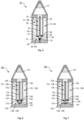
- Fig. 6 and Fig. 7 schematically illustrate a second exemplary embodiment of an aerosol-generating 140 article according to the present invention.
- the aerosol-generating article 140 according to Figs. 6 - 7 is very similar to the aerosol-generating article 40 shown in Figs. 1 - 3 . Therefore, identical or similar features are denoted with the same reference signs, yet incremented by 100.
- the article 140 according to Figs. 6 - 7 comprises a thermally driven actuator member 191 which is a star spring of a two-way shape-memory material.
- the actuator member 191 is attached to the second end cap 143.
- the star spring In a first phase at temperatures below the switching temperature of the shape-memory material, the star spring is in a bend configuration in which the arms of the star spring are bended out of plane, as shown in Fig. 6 . In a second phase at temperatures at or above the switching temperature of the shape-memory material, the star spring is in flat configuration, as shown in Fig. 7 .
- the article 140 comprises a sealing member 190 made of rubber.
- the disc-like sealing member 190 is fixedly attached to the star spring and laterally protrudes beyond the dimensions of the star spring. Due its flexible nature, the sealing member 190 may be deformed and thus follows the shape transformation of the star spring between the first phase and the second phase.
- the sealing member 190 is in flat configuration in which it clears the reservoir outlet 159.
- the sealing member 190 is deformed into a cup-like shape such as to sealingly cover the reservoir outlet 159 and the soaking section 175 of the liquid conduit.
- the thermally driven actuator member 191 may be made of a bi-metal which is in a bend configuration at temperatures below the operating temperature of the article during use and in a flat configuration at temperatures close to or at the operating temperature of the article during use.
- FIGS. 6 - 7 show an exemplary embodiment of a sealing member that is deformable between a closed configuration and an open configuration
- Figs. 1 - 3 show an exemplary embodiment of a sealing member that is displaceable between a closed configuration and an open configuration. Both embodiments fall within the term of a sealing member that is "transferrable" between a closed configuration and an open configuration.
- Fig. 8 schematically illustrates a second exemplary embodiment of an aerosol-generating system 280 according to the present invention.
- the system 280 comprises an aerosol-generating article 240 and an aerosol-generating device 260 for use with the article 240, both of which are similar to the aerosol-generating article 80 and the aerosol-generating device 60 of the aerosol-generating system 80 shown in Fig. 4 . Therefore, identical or similar features are denoted with the same reference signs, yet incremented by 200.
- the article 240 according to Fig. 8 comprises a magnetically driven actuator member 295.
- the magnetically driven actuator member comprise a piston 295 made of a ferromagnetic material which is movable at least from a first position into a second position by interaction with a magnetic coil 297 of the aerosol-generating device 260.
- the magnetic coil 297 and the ferromagnetic piston 295 form a moving iron actuator.
- the magnetic coil 297 is arranged close to the bottom portion of the cavity 262 of the device 260 such that the ferromagnetic piston 295 may experience the magnetic field of the magnetic coil 297, when the article is received in the cavity 262. Hence, when the magnetic coil 297 is switched on, as shown in Fig.
- the ferromagnetic piston 295 is attracted by the coil 297 and thus moves in a direction opposite the reservoir outlet 259.
- the sealing member 290 is fixedly attached to the piston 295, the latter lifts off the sealing member 290 from the bushing 245 such as to free the reservoir outlet 259.
- the magnetic coil 297 is switched off, the ferromagnetic piston 295 is not attracted anymore.
- the article 240 further comprises a return mechanism.
- the return mechanism comprises a helical return spring 296 which is arranged around the piston and abuts against the inner surface of the second end cap 243 at one side and against the sealing member 290 at the other side.
- the aerosol-generating device may be configured such as to activate the magnetic coil in response to at least one of a user input or a start of the heating operation for heating the aerosol-forming liquid or the insertion of the article into the aerosol-generating device.
- the aerosol-generating device may be configured such as to de-activate the magnetic coil in response to at least one of a user input or a stop of the heating operation for heating the aerosol-forming liquid or the removal of the article from the aerosol-generating device.
- Fig. 10 schematically illustrates a third exemplary embodiment of an aerosol-generating system 380 according to the present invention.
- the system 380 comprises an aerosol-generating article 340 and an aerosol-generating device 360 for use with the article 340, both of which are similar to the aerosol-generating article 80 and the aerosol-generating device 60 of the aerosol-generating system 80 shown in Fig. 4 . Therefore, identical or similar features are denoted with the same reference signs, yet incremented by 300.
- the 10 comprises a mechanical-contact driven actuator member 393 configured and arranged to mechanically interact with the aerosol-generating device 360 when being inserted into the aerosol-generating device 360 such as to be transferred from a first configuration into a second configuration, thereby transferring the sealing member 390 from the closed configuration into the open configuration.
- the mechanical-contact driven actuator member 393 is a flexible wall member made of an elastic material, such as silicone, which forms the bottom portion of the second end cap 343.
- the sealing member 390 is a flexible tube made of elastic membrane material which comprises a plurality of slits 395 through the tube wall extending along the tube axis.
- the slitted tube-like sealing member 390 is attached at its one end at the flexible actuator member 393, and at its other end at the bushing 345.
- the flexible actuator member 393 gets in contact with a pusher, which in the present embodiment is a piston-like protrusion 397 at the bottom of the cavity 362. This causes the flexible actuator member 393 to be deformed towards the interior of the article 340. Due to this deformation of the actuator member 393, the slitted tube-like sealing member 390 is compressed such as to bulge outwardly.
- the slits 395 through the tube wall of the sealing member 390 open up, thereby allowing aerosol-forming liquid to enter the interior of the tube-like sealing member 390 and thus to get into fluid communication with the liquid conduit 370 in the reservoir outlet 359.
- the flexible actuator member 393 returns back into its flat (non-deformed) configuration due to its elastic nature.
- the tube-like sealing member 390 returns back into its extended (non-bulged) configuration, due to its elastic nature and due to the flexible actuator member 393 straightening it when the actuator member 393 returns back into its flat configuration.
- the extended (non-bulged) configuration of the sealing member 390 as shown in Fig.
- the sealing member 390 according to Fig. 10 - 11 is another example of a sealing member that is deformable between a closed configuration, as shown in Fig. 11 , and an open configuration, as shown in Fig. 10 .
Landscapes
- Physics & Mathematics (AREA)
- Electromagnetism (AREA)
- Engineering & Computer Science (AREA)
- Power Engineering (AREA)
- General Engineering & Computer Science (AREA)
- Mechanical Engineering (AREA)
- Containers And Packaging Bodies Having A Special Means To Remove Contents (AREA)
- Nozzles (AREA)
Claims (25)
- Aerosolerzeugender Artikel (140) zum Gebrauch mit einer Aerosolerzeugungsvorrichtung, der Artikel (140) umfassend:- einen Flüssigkeitsvorratsbehälter zum Lagern einer aerosolbildenden Flüssigkeit (150), wobei der Flüssigkeitsvorratsbehälter einen Vorratsbehälterauslass (159) umfasst;- ein Dichtungselement (190), das reversibel zwischen einer offenen Konfiguration und einer geschlossenen Konfiguration überführbar ist, um den Vorratsbehälterauslass (159) zu öffnen bzw. dichtend zu verschließen; und- ein Stellgliedelement (191), das mit dem Dichtungselement (190) wirkverbunden ist, um das Dichtungselement (190) wenigstens von der geschlossenen Konfiguration in die offene Konfiguration zu überführen,wobei das Stellgliedelement (191) ein thermisch angetriebenes Stellgliedelement (191) ist, das ein Bimetall umfasst, und wobei das Dichtungselement (190) zwischen der geschlossenen Konfiguration und der offenen Konfiguration verschiebbar oder verformbar ist.
- Aerosolerzeugender Artikel (40) zum Gebrauch mit einer Aerosolerzeugungsvorrichtung (60), der Artikel (40) umfassend:- einen Flüssigkeitsvorratsbehälter zum Lagern einer aerosolbildenden Flüssigkeit (50), wobei der Flüssigkeitsvorratsbehälter einen Vorratsbehälterauslass (59) umfasst;- ein Dichtungselement (90), das reversibel zwischen einer offenen Konfiguration und einer geschlossenen Konfiguration überführbar ist, um den Vorratsbehälterauslass (59) zu öffnen bzw. dichtend zu verschließen; und- ein Stellgliedelement (91), das mit dem Dichtungselement (90) wirkverbunden ist, um das Dichtungselement (90) wenigstens von der geschlossenen Konfiguration in die offene Konfiguration zu überführen,wobei das Stellgliedelement (91) ein thermisch angetriebenes Stellgliedelement (91) ist, das ein Formgedächtnismaterial umfasst, und wobei das Dichtungselement (90) zwischen einer flachen Form in der offenen Konfiguration bzw. in der geschlossenen Konfiguration und einer gekrümmten Form in der geschlossenen Konfiguration bzw. in der offenen Konfiguration verformbar ist, und wobei das thermisch angetriebene Stellgliedelement (91) sich bei Erwärmung derart biegt, dass das Dichtungselement (90) von einer geschlossenen Konfiguration in eine offene Konfiguration überführt wird.
- Aerosolerzeugender Artikel (40, 140) nach Anspruch 1 oder 2, wobei das thermisch angetriebene Stellgliedelement (91, 191) wenigstens eine temperaturbetätigte Feder umfasst.
- Aerosolerzeugender Artikel (40, 140) nach einem der Ansprüche 1 bis 3, wobei das thermisch angetriebene Stellgliedelement (91, 191) induktiv erwärmbar ist und ein Suszeptormaterial umfasst.
- Aerosolerzeugender Artikel (240) zum Gebrauch mit einer Aerosolerzeugungsvorrichtung (260), der Artikel (240) umfassend:- einen Flüssigkeitsvorratsbehälter zum Lagern einer aerosolbildenden Flüssigkeit (250), wobei der Flüssigkeitsvorratsbehälter einen Vorratsbehälterauslass (259) umfasst;- ein Dichtungselement (290), das reversibel zwischen einer offenen Konfiguration und einer geschlossenen Konfiguration überführbar ist, um den Vorratsbehälterauslass (259) zu öffnen bzw. dichtend zu verschließen; und- ein Stellgliedelement (295), das mit dem Dichtungselement (290) wirkverbunden ist, um das Dichtungselement (290) wenigstens von der geschlossenen Konfiguration in die offene Konfiguration zu überführen, wobei das Stellglied (295) ein magnetisch angetriebenes Stellglied (295) ist;wobei das magnetisch angetriebene Stellgliedelement (295) einen Permanentmagneten umfasst, der durch Wechselwirkung mit einer Magnetspule (297), einem Permanentmagneten oder einem magnetischen Material der Aerosolerzeugungsvorrichtung (260) wenigstens von einer ersten Position in eine zweite Position bewegbar ist, wodurch das Dichtungselement (290) von der geschlossenen Konfiguration in die offene Konfiguration überführt wird.
- Aerosolerzeugender Artikel (240) zum Gebrauch mit einer Aerosolerzeugungsvorrichtung (260), der Artikel (240) umfassend:- einen Flüssigkeitsvorratsbehälter zum Lagern einer aerosolbildenden Flüssigkeit (250), wobei der Flüssigkeitsvorratsbehälter einen Vorratsbehälterauslass (259) umfasst;- ein Dichtungselement (290), das reversibel zwischen einer offenen Konfiguration und einer geschlossenen Konfiguration überführbar ist, um den Vorratsbehälterauslass (259) zu öffnen bzw. dichtend zu verschließen; und- ein Stellgliedelement (295), das mit dem Dichtungselement (290) wirkverbunden ist, um das Dichtungselement (290) wenigstens von der geschlossenen Konfiguration in die offene Konfiguration zu überführen, wobei das Stellglied (295) ein magnetisch angetriebenes Stellglied (295) ist;wobei das magnetisch angetriebene Stellgliedelement (295) ein ferromagnetisches oder ferrimagnetisches Element umfasst, das durch Wechselwirkung mit einer Magnetspule (297) oder einem Permanentmagneten der Aerosolerzeugungsvorrichtung (260) wenigstens von einer ersten Position in eine zweite Position bewegbar ist, wodurch das Dichtungselement (290) von der geschlossenen Konfiguration in die offene Konfiguration überführt wird.
- Aerosolerzeugender Artikel (340) zum Gebrauch mit einer Aerosolerzeugungsvorrichtung (360), der Artikel (340) umfassend- einen Flüssigkeitsvorratsbehälter zum Lagern einer aerosolbildenden Flüssigkeit (350), wobei der Flüssigkeitsvorratsbehälter einen Vorratsbehälterauslass (359) umfasst;- ein Dichtungselement (390), das reversibel zwischen einer offenen Konfiguration und einer geschlossenen Konfiguration überführbar ist, um den Vorratsbehälterauslass (359) zu öffnen bzw. dichtend zu verschließen; und- ein Stellgliedelement (393), das mit dem Dichtungselement (390) wirkverbunden ist, um das Dichtungselement (390) wenigstens von der geschlossenen Konfiguration in die offene Konfiguration zu überführen,wobei das Stellgliedelement (393) ein durch mechanischen Kontakt angetriebenes Stellgliedelement (393) ist, das ausgelegt und angeordnet ist, um bei dem Einsetzen in die Aerosolerzeugungsvorrichtung (360) mechanisch mit der Aerosolerzeugungsvorrichtung (360) zusammenzuwirken, um von einer ersten Konfiguration in eine zweite Konfiguration überführt zu werden, wodurch das Dichtungselement (390) von der geschlossenen Konfiguration in die offene Konfiguration überführt wird, wobei das durch mechanischen Kontakt angetriebene Stellgliedelement (393) ein flexibles Wandelement des aerosolerzeugenden Artikels (340) ist.
- Aerosolerzeugender Artikel (40, 140, 240, 340) nach einem beliebigen der vorhergehenden Ansprüche, wobei das Stellgliedelement (91, 191, 295, 393) zum Überführen des Dichtungselements (90, 190, 290, 390) von der offenen Konfiguration in die geschlossene Konfiguration ausgelegt ist.
- Aerosolerzeugender Artikel (40, 140, 240, 340) nach einem beliebigen der vorhergehenden Ansprüche, wobei das Stellgliedelement und das Dichtungselement einstückig miteinander ausgebildet sind.
- Aerosolerzeugender Artikel (340) nach einem der beliebigen vorhergehenden Ansprüche, wobei das Dichtungselement (390) einen flexiblen Schlauch umfasst, der aus einem elastischen Membranmaterial hergestellt ist.
- Aerosolerzeugender Artikel (340) nach Anspruch 10, wobei der flexible Schlauch eine Vielzahl von Schlitzen (395) durch die Schlauchwand umfasst, die sich entlang einer Längsachse des flexiblen Schlauchs erstrecken.
- Aerosolerzeugender Artikel (40, 140, 240, 340) nach einem beliebigen der vorhergehenden Ansprüche, ferner umfassend einen Rückführmechanismus, der zum Überführen des Dichtungselements (90, 190, 290, 390) von der offenen Konfiguration in die geschlossene Konfiguration angeordnet und ausgelegt ist.
- Aerosolerzeugender Artikel (40, 140, 240, 340) nach einem beliebigen der vorhergehenden Ansprüche, ferner umfassend eine Flüssigkeitsleitung (70, 170, 270, 370) zur Abgabe von aerosolbildender Flüssigkeit (50, 150, 250, 350) aus dem Flüssigkeitsvorratsbehälter durch den Vorratsbehälterauslass (59, 159, 259, 359) in eine Region außerhalb des Flüssigkeitsvorratsbehälters, wenn sich das Dichtungselement (90, 190, 290, 390) in der offenen Konfiguration befindet.
- Aerosolerzeugender Artikel (40, 240) nach Anspruch 13, wobei die Flüssigkeitsleitung (70, 270) derart an dem Dichtungselement (90, 290) angebracht ist, dass sie zusammen mit dem Dichtungselement (90, 290) zwischen einer ersten Position und einer zweiten Position überführbar ist.
- Aerosolerzeugender Artikel (40, 140, 240, 340) nach einem beliebigen von Anspruch 13 oder Anspruch 14, wobei die Flüssigkeitsleitung (70, 170, 270, 370) eine induktiv erwärmbare Flüssigkeitsleitung ist.
- Aerosolerzeugender Artikel (40) nach einem beliebigen der Ansprüche 13 bis 14, wobei die Flüssigkeitsleitung (70) ein Dochtelement ist, insbesondere ein Filamentbündel mit einer Vielzahl von Filamenten (71, 72).
- Aerosolerzeugungssystem (80, 280, 380), umfassend eine Aerosolerzeugungsvorrichtung (60, 260, 360) und einen aerosolerzeugenden Artikel (40, 140, 240, 340) nach einem beliebigen der vorhergehenden Ansprüche zum Gebrauch mit der Vorrichtung (60, 260, 360).
- Aerosolerzeugungssystem (280), umfassend eine Aerosolerzeugungsvorrichtung (260) und einen aerosolerzeugenden Artikel (240) nach Anspruch 5 zum Gebrauch mit der Vorrichtung (260), wobei die Aerosolerzeugungsvorrichtung (260) eine Magnetspule (297), einen Permanentmagneten oder ein magnetisches Material zur Wechselwirkung mit dem Permanentmagneten des magnetisch angetriebenen Stellgliedelements (295) des Artikels (240) umfasst.
- Aerosolerzeugungssystem (280), umfassend eine Aerosolerzeugungsvorrichtung (260) und einen aerosolerzeugenden Artikel (240) nach Anspruch 6 zum Gebrauch mit der Vorrichtung (260), wobei die Aerosolerzeugungsvorrichtung (260) eine Magnetspule (297) oder einen Permanentmagneten zur Wechselwirkung mit dem ferromagnetischen oder ferrimagnetischen Stellgliedelement des magnetisch angetriebenen Stellgliedes (295) des Artikels (240) umfasst.
- Aerosolerzeugungssystem (380), umfassend eine Aerosolerzeugungsvorrichtung (360) und einen aerosolerzeugenden Artikel (340) nach Anspruch 7 zum Gebrauch mit der Vorrichtung (360), wobei die Aerosolerzeugungsvorrichtung (360) einen Schieber oder einen Riegel umfasst, der/die, wenn der Artikel (340) in die Aerosolerzeugungsvorrichtung (360) eingesetzt wird, zum Überführen des Stellgliedelements (393) des aerosolerzeugenden Artikels (340) von einer ersten Konfiguration in eine zweite Konfiguration angeordnet und ausgelegt ist, wodurch das Dichtungselement (390) von der geschlossenen Konfiguration in die offene Konfiguration überführt wird.
- Aerosolerzeugungssystem (380) nach Anspruch 20, wobei der Schieber oder der Riegel ein beweglicher Schieber oder ein beweglicher Riegel ist.
- Aerosolerzeugungssystem (380) nach Anspruch 21, wobei eine Bewegung des beweglichen Schiebers oder des beweglichen Riegels manuell durch einen Benutzer, der den beweglichen Schieber oder den beweglichen Riegel betätigt, oder durch ein elektrisch oder magnetisch angetriebenes Stellglied bewirkt wird.
- Aerosolerzeugungssystem (380) nach Anspruch 20, wobei der Schieber oder der Riegel ein stationärer Schieber oder ein stationärer Riegel ist.
- Aerosolerzeugungssystem (80, 180), umfassend eine Aerosolerzeugungsvorrichtung (60) und einen aerosolerzeugenden Artikel (40, 140) nach einem der Ansprüche 1 bis 4, wobei die Aerosolerzeugungsvorrichtung (60) eine Erwärmungsanordnung zum Erwärmen des thermisch angetriebenen Stellgliedelements (91, 191) umfasst, wenn der Artikel (40, 140) in die Aerosolerzeugungsvorrichtung (60) eingesetzt wird, um das Dichtungselement (90, 190) von der geschlossenen Konfiguration in die offene Konfiguration zu überführen.
- Aerosolerzeugungssystem (80, 180) nach Anspruch 24, wobei die Erwärmungsanordnung eine gemeinsame Erwärmungsanordnung ist, die zum Betätigen des thermisch angetriebenen Stellgliedelements (91, 191) und zum Verdampfen der aerosolbildenden Flüssigkeit (50, 150) verwendet wird.
Applications Claiming Priority (2)
| Application Number | Priority Date | Filing Date | Title |
|---|---|---|---|
| EP20175053 | 2020-05-15 | ||
| PCT/EP2021/062571 WO2021228913A2 (en) | 2020-05-15 | 2021-05-12 | Aerosol-generating article comprising a liquid reservoir and a transferrable sealing member |
Publications (3)
| Publication Number | Publication Date |
|---|---|
| EP4149299A2 EP4149299A2 (de) | 2023-03-22 |
| EP4149299C0 EP4149299C0 (de) | 2024-10-23 |
| EP4149299B1 true EP4149299B1 (de) | 2024-10-23 |
Family
ID=70738436
Family Applications (1)
| Application Number | Title | Priority Date | Filing Date |
|---|---|---|---|
| EP21725737.7A Active EP4149299B1 (de) | 2020-05-15 | 2021-05-12 | Aerosolerzeugender artikel mit einem flüssigkeitsreservoir und einem bewegbaren dichtungselement |
Country Status (6)
| Country | Link |
|---|---|
| US (1) | US20230210188A1 (de) |
| EP (1) | EP4149299B1 (de) |
| JP (1) | JP7713960B2 (de) |
| KR (1) | KR20230011344A (de) |
| CN (1) | CN115605102A (de) |
| WO (1) | WO2021228913A2 (de) |
Families Citing this family (4)
| Publication number | Priority date | Publication date | Assignee | Title |
|---|---|---|---|---|
| JP7360400B2 (ja) * | 2018-05-25 | 2023-10-12 | フィリップ・モーリス・プロダクツ・ソシエテ・アノニム | サセプタチューブを含むエアロゾル発生のためのサセプタ組立品 |
| EP4159058B1 (de) * | 2020-05-29 | 2024-10-30 | Shenzhen Smoore Technology Limited | Zerstäuber und elektronische zerstäubungsvorrichtung |
| WO2023198691A1 (en) * | 2022-04-13 | 2023-10-19 | Jt International S.A. | Automatic closure for an aerosol generating device |
| CN116268625A (zh) * | 2023-03-23 | 2023-06-23 | 深圳市赛尔美电子科技有限公司 | 液体定向导流组件、电子雾化装置及液体定向导流方法 |
Citations (11)
| Publication number | Priority date | Publication date | Assignee | Title |
|---|---|---|---|---|
| EP2460424A1 (de) | 2010-12-03 | 2012-06-06 | Philip Morris Products S.A. | Aerosolerzeugungssystem mit Leckagenschutz |
| US20130213418A1 (en) | 2012-02-22 | 2013-08-22 | Altria Client Services Inc. | Electronic smoking article |
| EP3100621A1 (de) | 2015-06-02 | 2016-12-07 | Fontem Holdings 1 B.V. | Elektronische rauchvorrichtung |
| CN104824846B (zh) | 2015-03-10 | 2017-08-18 | 深圳麦克韦尔股份有限公司 | 电子烟 |
| WO2018071337A1 (en) | 2016-10-10 | 2018-04-19 | Innovosciences Llc | Hand-held inhalable vapor producing device and method |
| US10080388B2 (en) | 2017-01-25 | 2018-09-25 | Rai Strategic Holdings, Inc. | Aerosol delivery device including a shape-memory alloy and a related method |
| US20190000134A1 (en) | 2015-07-10 | 2019-01-03 | Philip Morris Products S.A. | Aerosol-generating article comprising a liquid delivery element |
| US20190093783A1 (en) | 2017-09-25 | 2019-03-28 | Altria Client Services Llc | E-vapor device with bimetallic actuator for opening and sealing reservoir |
| WO2019115112A1 (en) | 2017-12-12 | 2019-06-20 | Jt International Sa | Fluid supply system for an electronic cigarette |
| EP3536174A1 (de) | 2007-12-18 | 2019-09-11 | Juul Labs, Inc. | Aerosolvorrichtungen und verfahren zum inhalieren von substanzen und deren verwendung |
| WO2019224531A1 (en) | 2018-05-23 | 2019-11-28 | Nicoventures Trading Limited | Electronic vapour provision system with aerosolisable substrate material dispensing arrangement |
Family Cites Families (10)
| Publication number | Priority date | Publication date | Assignee | Title |
|---|---|---|---|---|
| US3191610A (en) * | 1960-01-14 | 1965-06-29 | Gen Motors Corp | Centrifugal valve having variable curved elastic slitted tubes |
| US3721240A (en) * | 1970-11-10 | 1973-03-20 | M Tamburri | Mechanical smoking device |
| US6681998B2 (en) * | 2000-12-22 | 2004-01-27 | Chrysalis Technologies Incorporated | Aerosol generator having inductive heater and method of use thereof |
| GB0317330D0 (en) * | 2003-07-24 | 2003-08-27 | Diamond H Controls Ltd | Gas valve mechanism and multi-port valve |
| US20110290248A1 (en) * | 2010-05-25 | 2011-12-01 | Steven Michael Schennum | Aerosol Generator |
| GB2530980A (en) * | 2014-09-19 | 2016-04-13 | Kind Consumer Ltd | Simulated cigarette |
| KR102618153B1 (ko) * | 2015-06-12 | 2023-12-27 | 필립모리스 프로덕츠 에스.에이. | 디스펜싱 메커니즘 |
| DE102015226691A1 (de) * | 2015-12-23 | 2017-06-29 | Trelleborg Sealing Solutions Germany Gmbh | Rotationsdichtungsanordnung und Rotationsdichtung mit Schraubenfederdichtelement |
| DE102016219630A1 (de) * | 2016-10-10 | 2018-04-12 | Mack & Schneider Gmbh | Ventileinrichtung |
| CN113382647B (zh) * | 2018-11-05 | 2024-08-30 | 尤尔实验室有限公司 | 用于蒸发器装置的料筒 |
-
2021
- 2021-05-12 US US17/998,273 patent/US20230210188A1/en active Pending
- 2021-05-12 EP EP21725737.7A patent/EP4149299B1/de active Active
- 2021-05-12 CN CN202180034986.2A patent/CN115605102A/zh active Pending
- 2021-05-12 KR KR1020227043605A patent/KR20230011344A/ko active Pending
- 2021-05-12 JP JP2022567763A patent/JP7713960B2/ja active Active
- 2021-05-12 WO PCT/EP2021/062571 patent/WO2021228913A2/en not_active Ceased
Patent Citations (11)
| Publication number | Priority date | Publication date | Assignee | Title |
|---|---|---|---|---|
| EP3536174A1 (de) | 2007-12-18 | 2019-09-11 | Juul Labs, Inc. | Aerosolvorrichtungen und verfahren zum inhalieren von substanzen und deren verwendung |
| EP2460424A1 (de) | 2010-12-03 | 2012-06-06 | Philip Morris Products S.A. | Aerosolerzeugungssystem mit Leckagenschutz |
| US20130213418A1 (en) | 2012-02-22 | 2013-08-22 | Altria Client Services Inc. | Electronic smoking article |
| CN104824846B (zh) | 2015-03-10 | 2017-08-18 | 深圳麦克韦尔股份有限公司 | 电子烟 |
| EP3100621A1 (de) | 2015-06-02 | 2016-12-07 | Fontem Holdings 1 B.V. | Elektronische rauchvorrichtung |
| US20190000134A1 (en) | 2015-07-10 | 2019-01-03 | Philip Morris Products S.A. | Aerosol-generating article comprising a liquid delivery element |
| WO2018071337A1 (en) | 2016-10-10 | 2018-04-19 | Innovosciences Llc | Hand-held inhalable vapor producing device and method |
| US10080388B2 (en) | 2017-01-25 | 2018-09-25 | Rai Strategic Holdings, Inc. | Aerosol delivery device including a shape-memory alloy and a related method |
| US20190093783A1 (en) | 2017-09-25 | 2019-03-28 | Altria Client Services Llc | E-vapor device with bimetallic actuator for opening and sealing reservoir |
| WO2019115112A1 (en) | 2017-12-12 | 2019-06-20 | Jt International Sa | Fluid supply system for an electronic cigarette |
| WO2019224531A1 (en) | 2018-05-23 | 2019-11-28 | Nicoventures Trading Limited | Electronic vapour provision system with aerosolisable substrate material dispensing arrangement |
Also Published As
| Publication number | Publication date |
|---|---|
| KR20230011344A (ko) | 2023-01-20 |
| JP2023527687A (ja) | 2023-06-30 |
| WO2021228913A3 (en) | 2022-02-10 |
| EP4149299C0 (de) | 2024-10-23 |
| EP4149299A2 (de) | 2023-03-22 |
| US20230210188A1 (en) | 2023-07-06 |
| CN115605102A (zh) | 2023-01-13 |
| JP7713960B2 (ja) | 2025-07-28 |
| WO2021228913A2 (en) | 2021-11-18 |
Similar Documents
| Publication | Publication Date | Title |
|---|---|---|
| EP4149299B1 (de) | Aerosolerzeugender artikel mit einem flüssigkeitsreservoir und einem bewegbaren dichtungselement | |
| JP7209069B2 (ja) | 平面誘導コイルを備えるエアロゾル発生システム | |
| CN114144081B (zh) | 用于气溶胶生成装置的扩张感受器加热装置 | |
| EP3232842B1 (de) | Aerosolerzeugungsvorrichtung | |
| KR20230003664A (ko) | 내부 기류 통로를 구비한 카트리지를 포함하는 에어로졸 발생 시스템 | |
| EP4149293B1 (de) | Aerosolerzeugender artikel mit einem hauptreservoir und einem kapillaren pufferreservoir | |
| EP4149291B1 (de) | Flüssigkeitsfördernde suszeptoranordnung zum fördern und induktiven erwärmen einer aerosolbildenden flüssigkeit | |
| JP2025178271A (ja) | エアロゾル形成液体を搬送および誘導加熱するための液体搬送サセプタ組立品 | |
| RU2829801C1 (ru) | Изделие, генерирующее аэрозоль, содержащее резервуар для жидкости и перемещающийся уплотнительный элемент (варианты), и система, содержащая такое изделие (варианты) | |
| EP4149290B1 (de) | Aerosolerzeugungsartikel mit flüssigkeitsfördernder suszeptoranordnung | |
| EP4255233B1 (de) | Patrone eines stabförmigen aerosolerzeugungesgegenstandes zur verwendung mit einem induktiv geheizten aerosolerzeugungsgerät | |
| EP4255236B1 (de) | Patrone eines stabförmigen aerosolerzeugungsgegenstandes zur verwendung mit einem induktiv geheizten aerosolerzeugungsgerät | |
| EP4149294B1 (de) | Aerosolerzeugender artikel mit einem flüssigkeitsbehälter mit mehreren kammern | |
| JPWO2021228913A5 (de) | ||
| KR20250048701A (ko) | 기류 유도 요소를 갖는 카트리지 | |
| RU2796251C2 (ru) | Электронагреваемая система, генерирующая аэрозоль, а также электрически нагреваемое устройство, генерирующее аэрозоль |
Legal Events
| Date | Code | Title | Description |
|---|---|---|---|
| STAA | Information on the status of an ep patent application or granted ep patent |
Free format text: STATUS: UNKNOWN |
|
| STAA | Information on the status of an ep patent application or granted ep patent |
Free format text: STATUS: THE INTERNATIONAL PUBLICATION HAS BEEN MADE |
|
| PUAI | Public reference made under article 153(3) epc to a published international application that has entered the european phase |
Free format text: ORIGINAL CODE: 0009012 |
|
| STAA | Information on the status of an ep patent application or granted ep patent |
Free format text: STATUS: REQUEST FOR EXAMINATION WAS MADE |
|
| 17P | Request for examination filed |
Effective date: 20221205 |
|
| AK | Designated contracting states |
Kind code of ref document: A2 Designated state(s): AL AT BE BG CH CY CZ DE DK EE ES FI FR GB GR HR HU IE IS IT LI LT LU LV MC MK MT NL NO PL PT RO RS SE SI SK SM TR |
|
| DAV | Request for validation of the european patent (deleted) | ||
| DAX | Request for extension of the european patent (deleted) | ||
| GRAP | Despatch of communication of intention to grant a patent |
Free format text: ORIGINAL CODE: EPIDOSNIGR1 |
|
| STAA | Information on the status of an ep patent application or granted ep patent |
Free format text: STATUS: GRANT OF PATENT IS INTENDED |
|
| INTG | Intention to grant announced |
Effective date: 20240103 |
|
| GRAJ | Information related to disapproval of communication of intention to grant by the applicant or resumption of examination proceedings by the epo deleted |
Free format text: ORIGINAL CODE: EPIDOSDIGR1 |
|
| STAA | Information on the status of an ep patent application or granted ep patent |
Free format text: STATUS: REQUEST FOR EXAMINATION WAS MADE |
|
| GRAP | Despatch of communication of intention to grant a patent |
Free format text: ORIGINAL CODE: EPIDOSNIGR1 |
|
| STAA | Information on the status of an ep patent application or granted ep patent |
Free format text: STATUS: GRANT OF PATENT IS INTENDED |
|
| INTC | Intention to grant announced (deleted) | ||
| INTG | Intention to grant announced |
Effective date: 20240515 |
|
| GRAS | Grant fee paid |
Free format text: ORIGINAL CODE: EPIDOSNIGR3 |
|
| GRAA | (expected) grant |
Free format text: ORIGINAL CODE: 0009210 |
|
| STAA | Information on the status of an ep patent application or granted ep patent |
Free format text: STATUS: THE PATENT HAS BEEN GRANTED |
|
| AK | Designated contracting states |
Kind code of ref document: B1 Designated state(s): AL AT BE BG CH CY CZ DE DK EE ES FI FR GB GR HR HU IE IS IT LI LT LU LV MC MK MT NL NO PL PT RO RS SE SI SK SM TR |
|
| REG | Reference to a national code |
Ref country code: GB Ref legal event code: FG4D |
|
| REG | Reference to a national code |
Ref country code: CH Ref legal event code: EP |
|
| REG | Reference to a national code |
Ref country code: DE Ref legal event code: R096 Ref document number: 602021020651 Country of ref document: DE |
|
| REG | Reference to a national code |
Ref country code: IE Ref legal event code: FG4D |
|
| U01 | Request for unitary effect filed |
Effective date: 20241023 |
|
| U07 | Unitary effect registered |
Designated state(s): AT BE BG DE DK EE FI FR IT LT LU LV MT NL PT RO SE SI Effective date: 20241029 |
|
| PG25 | Lapsed in a contracting state [announced via postgrant information from national office to epo] |
Ref country code: IS Free format text: LAPSE BECAUSE OF FAILURE TO SUBMIT A TRANSLATION OF THE DESCRIPTION OR TO PAY THE FEE WITHIN THE PRESCRIBED TIME-LIMIT Effective date: 20250223 Ref country code: HR Free format text: LAPSE BECAUSE OF FAILURE TO SUBMIT A TRANSLATION OF THE DESCRIPTION OR TO PAY THE FEE WITHIN THE PRESCRIBED TIME-LIMIT Effective date: 20241023 |
|
| PG25 | Lapsed in a contracting state [announced via postgrant information from national office to epo] |
Ref country code: ES Free format text: LAPSE BECAUSE OF FAILURE TO SUBMIT A TRANSLATION OF THE DESCRIPTION OR TO PAY THE FEE WITHIN THE PRESCRIBED TIME-LIMIT Effective date: 20241023 |
|
| PG25 | Lapsed in a contracting state [announced via postgrant information from national office to epo] |
Ref country code: NO Free format text: LAPSE BECAUSE OF FAILURE TO SUBMIT A TRANSLATION OF THE DESCRIPTION OR TO PAY THE FEE WITHIN THE PRESCRIBED TIME-LIMIT Effective date: 20250123 |
|
| PG25 | Lapsed in a contracting state [announced via postgrant information from national office to epo] |
Ref country code: GR Free format text: LAPSE BECAUSE OF FAILURE TO SUBMIT A TRANSLATION OF THE DESCRIPTION OR TO PAY THE FEE WITHIN THE PRESCRIBED TIME-LIMIT Effective date: 20250124 |
|
| PG25 | Lapsed in a contracting state [announced via postgrant information from national office to epo] |
Ref country code: PL Free format text: LAPSE BECAUSE OF FAILURE TO SUBMIT A TRANSLATION OF THE DESCRIPTION OR TO PAY THE FEE WITHIN THE PRESCRIBED TIME-LIMIT Effective date: 20241023 |
|
| PG25 | Lapsed in a contracting state [announced via postgrant information from national office to epo] |
Ref country code: RS Free format text: LAPSE BECAUSE OF FAILURE TO SUBMIT A TRANSLATION OF THE DESCRIPTION OR TO PAY THE FEE WITHIN THE PRESCRIBED TIME-LIMIT Effective date: 20250123 |
|
| U20 | Renewal fee for the european patent with unitary effect paid |
Year of fee payment: 5 Effective date: 20250528 |
|
| PG25 | Lapsed in a contracting state [announced via postgrant information from national office to epo] |
Ref country code: SM Free format text: LAPSE BECAUSE OF FAILURE TO SUBMIT A TRANSLATION OF THE DESCRIPTION OR TO PAY THE FEE WITHIN THE PRESCRIBED TIME-LIMIT Effective date: 20241023 |
|
| PGFP | Annual fee paid to national office [announced via postgrant information from national office to epo] |
Ref country code: GB Payment date: 20250527 Year of fee payment: 5 |
|
| PLBI | Opposition filed |
Free format text: ORIGINAL CODE: 0009260 |
|
| PGFP | Annual fee paid to national office [announced via postgrant information from national office to epo] |
Ref country code: CH Payment date: 20250601 Year of fee payment: 5 |
|
| PG25 | Lapsed in a contracting state [announced via postgrant information from national office to epo] |
Ref country code: SK Free format text: LAPSE BECAUSE OF FAILURE TO SUBMIT A TRANSLATION OF THE DESCRIPTION OR TO PAY THE FEE WITHIN THE PRESCRIBED TIME-LIMIT Effective date: 20241023 |
|
| PG25 | Lapsed in a contracting state [announced via postgrant information from national office to epo] |
Ref country code: CZ Free format text: LAPSE BECAUSE OF FAILURE TO SUBMIT A TRANSLATION OF THE DESCRIPTION OR TO PAY THE FEE WITHIN THE PRESCRIBED TIME-LIMIT Effective date: 20241023 |
|
| PLAX | Notice of opposition and request to file observation + time limit sent |
Free format text: ORIGINAL CODE: EPIDOSNOBS2 |
|
| 26 | Opposition filed |
Opponent name: NICOVENTURES TRADING LIMITED Effective date: 20250714 |
|
| PLBB | Reply of patent proprietor to notice(s) of opposition received |
Free format text: ORIGINAL CODE: EPIDOSNOBS3 |