EP4149204B1 - Verfahren und vorrichtung zur durchführung einer ruhemodusmessung im rrc-inaktivzustand - Google Patents
Verfahren und vorrichtung zur durchführung einer ruhemodusmessung im rrc-inaktivzustand Download PDFInfo
- Publication number
- EP4149204B1 EP4149204B1 EP22195642.8A EP22195642A EP4149204B1 EP 4149204 B1 EP4149204 B1 EP 4149204B1 EP 22195642 A EP22195642 A EP 22195642A EP 4149204 B1 EP4149204 B1 EP 4149204B1
- Authority
- EP
- European Patent Office
- Prior art keywords
- sdt
- procedure
- idle mode
- message
- implementations
- Prior art date
- Legal status (The legal status is an assumption and is not a legal conclusion. Google has not performed a legal analysis and makes no representation as to the accuracy of the status listed.)
- Active
Links
Images


Classifications
-
- H—ELECTRICITY
- H04—ELECTRIC COMMUNICATION TECHNIQUE
- H04W—WIRELESS COMMUNICATION NETWORKS
- H04W76/00—Connection management
- H04W76/20—Manipulation of established connections
- H04W76/27—Transitions between radio resource control [RRC] states
-
- H—ELECTRICITY
- H04—ELECTRIC COMMUNICATION TECHNIQUE
- H04W—WIRELESS COMMUNICATION NETWORKS
- H04W24/00—Supervisory, monitoring or testing arrangements
- H04W24/10—Scheduling measurement reports ; Arrangements for measurement reports
-
- H—ELECTRICITY
- H04—ELECTRIC COMMUNICATION TECHNIQUE
- H04W—WIRELESS COMMUNICATION NETWORKS
- H04W48/00—Access restriction; Network selection; Access point selection
- H04W48/16—Discovering, processing access restriction or access information
-
- H—ELECTRICITY
- H04—ELECTRIC COMMUNICATION TECHNIQUE
- H04W—WIRELESS COMMUNICATION NETWORKS
- H04W52/00—Power management, e.g. Transmission Power Control [TPC] or power classes
- H04W52/02—Power saving arrangements
- H04W52/0209—Power saving arrangements in terminal devices
- H04W52/0225—Power saving arrangements in terminal devices using monitoring of external events, e.g. the presence of a signal
Definitions
- the present disclosure generally relates to wireless communications and, more specifically, to a method for performing an idle mode measurement in a radio resource control (RRC) inactive state, and to a user equipment (UE) configured to use such a method.
- RRC radio resource control
- UE user equipment
- next-generation wireless communication systems such as the fifth-generation (5G) New Radio (NR) system
- 5G fifth-generation
- NR New Radio
- the 5G NR system is designed to provide flexibility and configurability to optimize network services and types, accommodating various use cases such as enhanced Mobile Broadband (eMBB), massive Machine-Type Communication (mMTC), and Ultra-Reliable and Low-Latency Communication (URLLC).
- eMBB enhanced Mobile Broadband
- mMTC massive Machine-Type Communication
- URLLC Ultra-Reliable and Low-Latency Communication
- ZTE COROPORATION (RAPPORTEUR): "Introduction of SDT", 3GPP DRAFT; R2-2105927 , specifies the Radio Resource Control protocol for the radio interface between UE and NG-RAN, including: the radio related information transported in a transparent container between source gNB and target gNB upon inter gNB handover; the radio related information transported in a transparent container between a source or target gNB and another system upon inter RAT handover; and the radio related information transported in a transparent container between a source eNB and target gNB during E-UTRA-NR Dual Connectivity.
- WO 2023/009821 A1 which is published after the priority date of the present application, discloses a wireless device configured to receive, from a base station, a radio resource control, RRC, release message comprising a measurement configuration for one or more measurements by the wireless device while the wireless device is in an RRC inactive state and a small data transmission, SDT, configuration of a SDT procedure for transmission by the wireless device while the wireless device is in the RRC inactive state. While the wireless device is, based on the RRC release message, in the RRC inactive state, the wireless device initiates the SDT procedure based on the SDT configuration and does not perform, during the SDT procedure, measurements associated with the measurement configuration.
- RRC radio resource control
- SDT small data transmission
- the present disclosure is directed to a method for performing an idle mode measurement in a radio resource control (RRC) inactive state, and to user equipment (UE) configured to use the method.
- RRC radio resource control
- UE user equipment
- a method performed by a UE includes receiving and storing at least one idle mode measurement configuration from a first cell of a serving radio access network (RAN) via a downlink control signaling; determining whether a first small data transmission (SDT) procedure is ongoing while the UE is staying in an RRC inactive state; and determining whether to perform an idle mode measurement in the RRC inactive state according to the at least one idle mode measurement configuration and based on whether the first SDT procedure is ongoing.
- RAN serving radio access network
- SDT small data transmission
- the method further includes performing the idle mode measurement in the RRC inactive state in a case that the first SDT procedure is determined to be not ongoing, and not performing the idle mode measurement in the RRC inactive state in a case that the first SDT procedure is determined to be ongoing.
- whether the first SDT procedure is ongoing is determined based on whether an SDT failure detection timer is counting by the UE, and the method further includes performing the idle mode measurement in the RRC inactive state in a case that the SDT failure detection timer is not counting, and not performing the idle mode measurement in the RRC inactive state in a case that the SDT failure detection timer is counting.
- the method further includes starting to count an idle mode measurement timer to zero upon receiving the at least one idle mode measurement configuration.
- the at least one idle mode measurement configuration includes an initial value of the idle mode measurement timer.
- the UE keeps counting the idle mode measurement timer upon determining not to perform the idle mode measurement while the first SDT procedure is ongoing.
- the method further includes releasing the stored at least one idle mode measurement configuration in a case that the idle mode measurement timer expires.
- the at least one idle mode measurement configuration includes at least one of an idle/inactive measurement configuration or a logged measurement configuration.
- the first SDT procedure is a random access-small data transmission (RA-SDT) procedure or a configured grant-small data transmission (CG-SDT) procedure.
- R-SDT random access-small data transmission
- CG-SDT configured grant-small data transmission
- the at least one idle mode measurement configuration is received from the first cell of the serving RAN via one or more SDT packet receptions during a second SDT procedure.
- the method further includes transmitting at least one idle mode measurement report to a second cell of the serving RAN via one or more SDT packet transmissions during the first SDT procedure.
- the serving RAN includes at least one of a New Radio (NR) cell or an evolved-universal terrestrial radio access (E-UTRA) cell, and each of the idle mode measurement configuration, the downlink control signaling and the SDT procedure is associated with an NR radio access technology (RAT) or an E-UTRA.
- NR New Radio
- E-UTRA evolved-universal terrestrial radio access
- a UE in a second aspect of the present disclosure, includes at least one processor, and at least one memory coupled to the at least one processor.
- the at least one memory stores at least one computer-executable instructions that, when executed by the at least one processor, causes the UE to perform operations.
- the operations include receiving and storing at least one idle mode measurement configuration from a first cell of a serving radio access network (RAN) via a downlink control signaling; determining whether a first small data transmission (SDT) procedure is ongoing while the UE is staying in an RRC inactive state; and determining whether to perform an idle mode measurement in the RRC inactive state according to the at least one idle mode measurement configuration and based on whether the first SDT procedure is ongoing.
- RAN serving radio access network
- SDT small data transmission
- the operations further include performing the idle mode measurement in the RRC inactive state in a case that the first SDT procedure is determined to be not ongoing, and not performing the idle mode measurement in the RRC inactive state in a case that the first SDT procedure is determined to be ongoing.
- whether the first SDT procedure is ongoing is determined based on whether an SDT failure detection timer is counting by the UE, and the operations further include performing the idle mode measurement in the RRC inactive state in a case that the SDT failure detection timer is not counting, and not performing the idle mode measurement in the RRC inactive state in a case that the SDT failure detection timer is counting.
- the operations further include starting to count an idle mode measurement timer to zero upon receiving the at least one idle mode measurement configuration.
- the at least one idle mode measurement configuration includes an initial value of the idle mode measurement timer.
- the UE keeps counting the idle mode measurement timer upon determining not to perform the idle mode measurement while the first SDT procedure is ongoing. Then, the UE still keeps counting the idle mode measurement timer upon determining to perform the idle mode measurement while the first SDT procedure is not ongoing.
- the operations further include releasing the stored at least one idle mode measurement configuration in a case that the idle mode measurement timer expires.
- the at least one idle mode measurement configuration includes at least one of an idle/inactive measurement configuration or a logged measurement configuration.
- the first SDT procedure is a random access-small data transmission (RA-SDT) procedure or a configured grant-small data transmission (CG-SDT) procedure.
- R-SDT random access-small data transmission
- CG-SDT configured grant-small data transmission
- the at least one idle mode measurement configuration is received from the first cell of the serving RAN via one or more SDT packet receptions during a second SDT procedure.
- the operations further include transmitting at least one idle mode measurement report to a second cell of the serving RAN via one or more SDT packet transmissions during the first SDT procedure.
- the serving RAN includes at least one of a New Radio (NR) cell or an evolved-universal terrestrial radio access (E-UTRA) cell, and each of the idle mode measurement configuration, the downlink control signaling and the SDT procedure is associated with an NR radio access technology (RAT) or an E-UTRA.
- NR New Radio
- E-UTRA evolved-universal terrestrial radio access
- references to "one implementation,” “an implementation,” “example implementation,” “various implementations,” “in some implementations,” “implementations of the present disclosure,” etc., may indicate that the implementation(s) of the present disclosure may include a particular feature, structure, or characteristic, but not every possible implementation of the present disclosure necessarily includes the particular feature, structure, or characteristic. Further, repeated use of the phrase “In some implementations,” “in an example implementation,” or “an implementation,” do not necessarily refer to the same implementation, although they may.
- a and/or B may represent that: A exists alone, A and B exist at the same time, and B exists alone.
- a and/or B and/or C may represent that at least one of A, B, and C exists.
- the character "/" used herein generally represents that the former and latter associated objects are in an "or" relationship.
- any network function(s) or algorithm(s) may be implemented by hardware, software, or a combination of software and hardware.
- Disclosed functions may correspond to modules that may be software, hardware, firmware, or any combination thereof.
- the software implementation may include computer-executable instructions stored on a computer-readable medium such as memory or other types of storage devices.
- one or more microprocessors or general-purpose computers with communication processing capability may be programmed with corresponding executable instructions and carry out the disclosed network function(s) or algorithm(s).
- the microprocessors or general-purpose computers may be formed of Application-Specific Integrated Circuits (ASICs), programmable logic arrays, and/or one or more Digital Signal Processors (DSPs).
- ASICs Application-Specific Integrated Circuits
- DSPs Digital Signal Processors
- the computer-readable medium may include, but is not limited to, Random Access Memory (RAM), Read-Only Memory (ROM), Erasable Programmable Read-Only Memory (EPROM), Electrically Erasable Programmable Read-Only Memory (EEPROM), flash memory, Compact Disc Read-Only Memory (CD-ROM), magnetic cassettes, magnetic tape, magnetic disk storage, or any other equivalent medium capable of storing computer-readable instructions.
- RAM Random Access Memory
- ROM Read-Only Memory
- EPROM Erasable Programmable Read-Only Memory
- EEPROM Electrically Erasable Programmable Read-Only Memory
- CD-ROM Compact Disc Read-Only Memory
- magnetic cassettes magnetic tape
- magnetic disk storage or any other equivalent medium capable of storing computer-readable instructions.
- a radio communication network architecture may typically include at least one Base Station (BS), at least one UE, and one or more optional network elements that provide connection towards a network.
- the UE may communicate with the network (e.g., a Core Network (CN), an Evolved Packet Core (EPC) network, an Evolved Universal Terrestrial Radio Access Network (E-UTRAN), a Next-Generation Core (NGC), or an Internet), through a Radio Access Network (RAN) established by the BS.
- CN Core Network
- EPC Evolved Packet Core
- E-UTRAN Evolved Universal Terrestrial Radio Access Network
- NGC Next-Generation Core
- Internet a Radio Access Network
- a UE may include, but is not limited to, a mobile station, a mobile terminal or device, a user communication radio terminal.
- a UE may be a portable radio equipment, which includes, but is not limited to, a mobile phone, a tablet, a wearable device, a sensor, or a Personal Digital Assistant (PDA) with wireless communication capability.
- PDA Personal Digital Assistant
- the UE may be configured to receive and transmit signals over an air interface to one or more cells in a RAN.
- a BS may include, but is not limited to, a Node B (NB) as in the Universal Mobile Telecommunication System (UMTS), an evolved Node B (eNB) as in the LTE-A, a Radio Network Controller (RNC) as in the UMTS, a Base Station Controller (BSC) as in the Global System for Mobile communications (GSM)/GSM Enhanced Data rates for GSM Evolution (EDGE) Radio Access Network (GERAN), a next-generation eNB (ng-eNB) as in an Evolved Universal Terrestrial Radio Access (E-UTRA) BS in connection with the 5GC, a next-generation Node B (gNB) as in the 5G Access Network (5G-AN), and any other apparatus capable of controlling radio communication and managing radio resources within a cell.
- the BS may connect to serve the one or more UEs through a radio interface to the network.
- a BS may be configured to provide communication services according to at least one of the following Radio Access Technologies (RATs): Worldwide Interoperability for Microwave Access (WiMAX), GSM (often referred to as 2G), GERAN, General Packet Radio Service (GPRS), UMTS (often referred to as 3G) based on basic Wideband-Code Division Multiple Access (W-CDMA), High-Speed Packet Access (HSPA), LTE, LTE-A, enhanced LTE (eLTE), NR (often referred to as 5G), and LTE-A Pro.
- RATs Radio Access Technologies
- the BS may be operable to provide radio coverage to a specific geographical area using a plurality of cells included in the RAN.
- the BS may support the operations of the cells.
- Each cell may be operable to provide services to at least one UE within its radio coverage. More specifically, each cell (often referred to as a serving cell) may provide services to serve one or more Ues within its radio coverage (e.g., each cell schedules the Downlink (DL) and optionally Uplink (UL) resources to at least one UE within its radio coverage for DL and optionally UL packet transmissions).
- the BS may communicate with one or more Ues in the radio communication system through the plurality of cells.
- a cell may allocate Sidelink (SL) resources for supporting Proximity Service (ProSe), LTE SL services, and LTE/NR Vehicle-to-Everything (V2X) services. Each cell may have overlapped coverage areas with other cells.
- MR-DC Multi-RAT Dual Connectivity
- a Primary Cell (Pcell) may refer to the SpCell of an MCG.
- a Primary SCG Cell (PSCell) may refer to the SpCell of an SCG.
- MCG may refer to a group of serving cells associated with the Master Node (MN), including the SpCell and optionally one or more Secondary Cells (Scells).
- An SCG may refer to a group of serving cells associated with the Secondary Node (SN), including the SpCell and optionally one or more Scells.
- the frame structure for NR is to support flexible configurations for accommodating various next-generation (e.g., 5G) communication requirements, such as eMBB, mMTC, and URLLC, while fulfilling high reliability, high data rate, and low latency requirements.
- 5G next-generation
- the orthogonal frequency-division multiplexing (OFDM) technology may serve as a baseline for an NR waveform.
- the scalable OFDM numerology such as the adaptive subcarrier spacing, the channel bandwidth, and the cyclic prefix (CP), may also be used.
- two coding schemes are considered for NR: (1) low-density parity-check (LDPC) code and (2) polar code.
- the coding scheme adaptation may be configured based on the channel conditions and/or the service applications.
- DL transmission data in a transmission time interval of a single NR frame, at least DL transmission data, a guard period, and UL transmission data should be included, where the respective portions of the DL transmission data, the guard period, and the UL transmission data should also be configurable, for example, based on the network dynamics of NR.
- an SL resource may also be provided in an NR frame to support ProSe services.
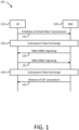
- FIG. 1 is a communication diagram illustrating communications between a UE and a RAN according to an example implementation of the present disclosure.
- RRC idle mode/inactive state packet transmission procedure which is also known as a small data transmission (SDT) procedure in some technical documents, such as 3GPP technical specifications.
- SDT small data transmission
- a UE may receive an SDT configuration from its serving cell (e.g., an Evolved Universal Terrestrial Radio Access (E-UTRA) cell or a New Radio (NR) cell) or its serving base station (e.g., an E-UTRA Network (E-UTRAN) eNB or an NR gNB)
- E-UTRA Evolved Universal Terrestrial Radio Access
- NR New Radio
- E-UTRAN E-UTRA Network
- NR gNB an E-UTRA Network
- the SDT configuration may be received while the UE is staying in an E-UTRA/NR RRC connected state.
- the SDT configuration may be transmitted via an RRCConnectionRelease / RRCRelease message which instructs the UE to move to an E-UTRA/NR RRC inactive state or an E-UTRA/NR RRC idle state.
- the SDT configuration may be transmitted via an RRCConnectionReconfiguration / RRCReconfiguration message while the UE is staying in the RRC connected state.
- the SDT configuration may be received while the UE is staying in an E-UTRA/NR RRC idle/inactive state.
- the SDT configuration may be transmitted via system information (e.g., SIB1 or other SI) via broadcasting approach or via SI on-demanding procedure.
- system information e.g., SIB1 or other SI
- the UE may store the received SDT configuration after the UE moves to or when the UE stays in the RRC inactive state.
- the UE 110 may initiate an SDT procedure 101 while one or more uplink data arrives as the AS layer forms the upper layers and/or when the criteria for SDT initiation are satisfied (e.g., based on pending UL data amount and data volume threshold, DL RSRP threshold, CG-SDT validation, RA-SDT validation, etc.) in the UE side.
- all or part of the arrived uplink packets are associated with one or more logical channels (or Radio Link Control (RLC) Bearers/radio bearers) which are enabled for the SDT (e.g., configured by the serving cell in the SDT configuration).
- the UE 110 may start an SDT procedure 101 to transmit the pending UL data while the UE 110 is staying in the RRC inactive state or after the UE 110 moves to the RRC inactive state.
- RLC Radio Link Control
- the UE 110 may be configured to transmit the pending UL data via one of the following approaches:
- the UE 110 may initiate an SDT procedure 101 by transmitting an uplink packet with or without an RRCResumeRequest message (action 131).
- the serving cell (as one of the operating (LTE/NR) cells in the NW 120) may allow (and may then further extend) the SDT procedure 101 (e.g., CG-SDT/RA-SDT procedure) by further configuring DL/UL dynamic grants to enable the UE 110/serving cell to keep exchanging pending DL/UL data in the subsequent data exchange phase (e.g., actions 133 to 139).
- the serving cell may transmit a DL control signaling (e.g., an RRCConnectionRelease message or an RRCRelease message) to the UE 110 to finish/terminate the SDT procedure 101 (action 141).
- a DL control signaling e.g., an RRCConnectionRelease message or an RRCRelease message
- the UE 110 may implement cell (re)selection procedure while the UE 110 is staying in the RRC inactive state and the UE 110 may be able to initiate an SDT procedure 101 to another cell (e.g., another operating cell configured in the NW 120) after cell (re)selection.
- another cell e.g., another operating cell configured in the NW 120
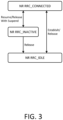
- the original serving cell which configures the SDT configuration to the UE 110 and then instructs the UE 110 to move to the RRC inactive state
- the serving cell and the anchor cell may be configured by different base stations and the base stations may communicate with each other via backhaul connections (e.g., X2 interface or Xn interface).
- the signaling radio bearers (e.g., SRB1 and/or SRB2) may also be resumed by the UE 110 for the SDT procedure 101.
- the signaling radio bearers e.g., SRB1 and/or SRB2
- some further control mechanisms may be needed in the UE side and/or the serving RAN because much AS/NAS control signaling could be transmitted via the SRB1/SRB2 during the SDT procedure 101 but some control signaling may be restricted/prohibited from being exchanged during the SDT procedure 101 (even though the SRB1/SRB2 is resumed during the SDT procedure 101).
- mechanisms that support AS/NAS control signaling exchange during the SDT procedure 101 are provided.
- the UE receives a dedicated idle/inactive measurement configuration via UE-specific control signaling (e.g., RRCRelease message).
- the idle/inactive measurement configuration may include any combination of target RAT information, target frequency carrier information, target cell information, and measurement criteria information.
- the UE may receive common/cell-specific idle/inactive measurement configuration via broadcasting system information (e.g., SIB1 ).
- a measurement duration may be configured within the idle/inactive measurement configuration.
- the UE After receiving the measurement duration, the UE starts a timer (e.g., T331) by setting its initial value to the received measurement duration.
- the UE stores the received idle/inactive measurement configuration and then implement/perform idle/inactive measurement while the timer (e.g., T331) is still counting-down/running. Then, if the timer (e.g., T331) is not running (e.g., stops or expires), the UE drops/releases the stored idle/inactive measurement configuration, and then the UE stops performing the idle/inactive measurement.
- the UE may receive the idle/inactive measurement configuration including the measurement duration from its serving cell via broadcasting system information.
- the UE may store the broadcast idle/inactive measurement configuration (e.g., while the timer (e.g., T331) is counting-down/running) and then implement/perform the idle/inactive measurement accordingly.
- the UE may implement idle/inactive measurement based on the broadcast idle/inactive measurement configuration (e.g., via System Information Blocks broadcasting) from its serving cell while the timer (e.g., T331) is not running according to different UE implementations.
- the timer e.g., T331
- the UE may transmit UL data with a multiplexed RRCResumeRequest message during an SDT procedure (e.g., a CG-SDT procedure or an RA-SDT procedure).
- an SDT procedure e.g., a CG-SDT procedure or an RA-SDT procedure.
- the purpose of the RRCResumeRequest message is not to resume its RRC connection (e.g., to move to the RRC connected state) with the serving RAN but to enable the serving cell to identify by which UE is the UL data transmitted.
- the UE may transmit an RRCResumeRequest message without being multiplexed with any UL pending data (e.g., RRCResumeRequest with ResumeCause or other Ies specific for SDT, which enables the serving cell to identify that the RRCResumeRequest message is transmitted by the UE for an SDT procedure).
- RRCResumeRequest without being multiplexed with any UL pending data (e.g., RRCResumeRequest with ResumeCause or other Ies specific for SDT, which enables the serving cell to identify that the RRCResumeRequest message is transmitted by the UE for an SDT procedure).
- the serving cell may transmit an RRCResume message to the UE to instruct the UE to move to the RRC connected state.
- the serving cell may not transmit the RRCResume message immediately right after receiving the RRCResumeRequest message (with or without multiplexed UL data). Instead, the serving cell may transmit the RRCResume message to the UE after the subsequent data exchange is completed after the UE transmits the RRCResumeRequest message to the serving cell.
- the RRCResumeRequest message generated by the UE for an SDT procedure may include a specific ResumeCause associated with the SDT procedure.
- the UE may use a specific ResumeCause (e.g., "SmallDataTransmission") to inform the serving cell that the purpose of this RRCResumeRequest message is for an SDT procedure.
- the specific ResumeCause may be configured with the UE status of an SDT procedure (e.g., whether the UE still has pending uplink packets staying in the Layer-2 buffer); therefore, the UE may inform the UE status to the serving cell by transmitting the specific ResumeCause within the RRCResumeRequest message after the UE initiates the SDT procedure.
- the UE may move to the RRC connected state and reply with the RRCResumeComplete message to the serving cell.
- the UE may transmit available idle/inactive measurement reports in the RRCResumeComplete message.
- the available idle/inactive measurement reports may be associated with one or more target RATs (e.g., E-UTRA and/or New Radio)/one or more target frequency carriers (e.g., frequency carrier list represented by NR-Absolute Radio-Frequency Channel Number (ARFCN) value and/or E-UTRA-ARFCN value)/one or more target cells (e.g., cell list represented by E-UTRA physical cell identities and/or NR physical cell identities).
- target RATs e.g., E-UTRA and/or New Radio
- target frequency carriers e.g., frequency carrier list represented by NR-Absolute Radio-Frequency Channel Number (ARFCN) value and/or E-UTRA-ARFCN value
- target cells e.g., cell list represented by E-UTRA physical cell identities and/or NR physical cell identities.
- the serving cell may transmit an RRCSetup message to the UE to instruct the LTE to move to the RRC connected state.
- the serving cell may not transmit the RRCSetup message immediately right after receiving the RRCResumeRequest message (with multiplexed UL data). Instead, the serving cell may transmit the RRCResume message to the UE after the subsequent data exchange is completed after the UE transmits the RRCResumeRequest message to the serving cell.
- the LTE may move to the RRC connected state and reply with an RRCSetupComplete message to the serving cell.
- the UE may move to the RRC idle state (or idle mode) and release the stored SDT configuration (e.g., CG-SDT/RA-SDT configuration).
- the MAC entity in the UE side e.g., the UE 110 shown in Fig. 1
- the MAC entity in the UE side may not be released in this situation therefore the pending uplink data may still be buffered in the MAC entity after the UE receives the RRCSetup message.
- the MAC entity may be released in this situation (e.g., after RRCSetup message reception) and the pending uplink data may be cleared after the UE receives the RRCSetup message.
- the UE may transmit available idle/inactive measurement reports in the RRCSetupComplete message.
- the serving cell may request the UE to transmit the idle/inactive measurements pending in the UE side by transmitting another idle/inactive measurement enquiry message to the UE.
- the RRCResumeRequest may be transmitted via Msg3 and/or MsgA, (e.g., if the SDT procedure is an RA-SDT procedure).
- the RRCResumeRequest may be transmitted via a UL resource configured by CG (e.g., if the SDT procedure is a CG-SDT procedure)
- the RRCResumeRequest may be transmitted via the very first UL transmission of the SDT procedure.
- the specific message may be transmitted via Msg4, MsgB, and/or via any DL assignment during the subsequent data transmission phase (e.g., if the SDT procedure is an RA-SDT procedure).
- the specific message may be transmitted via feedback (e.g., DL/UL scheduling) for the RRCResumeRequest message.
- the feedback may be transmitted within a window/timer for the CG-SDT procedure.
- the window/timer may be started after the UE transmits the RRCResumeRequest message.
- the specific message may be an RRC message, a MAC CE, and/or DCI.
- the UE may stay in the RRC inactive state, and/or may keep performing the SDT procedure.
- the UE may transmit available idle/inactive measurement reports via a UL resource (e.g., scheduled by a dynamic grant or configured by a CG-SDT configuration) during the SDT procedure.
- a UL resource e.g., scheduled by a dynamic grant or configured by a CG-SDT configuration
- the UE may be configured with an RRC-less SDT procedure, which means the UE may transmit one or more UL packets to the serving cell without transmitting the RRCResumeRequest message to the serving cell.
- the serving cell may transmit an RRCResume message or a dedicated RRC message to instruct the UE to move into the RRC connected state to the UE after the serving cell receives the UL data from the UE.
- the UE may move to the RRC connected state and reply with an RRCResumeComplete message or an RRC message responding to the dedicated RRC message (with available idle/inactive measurement reports).
- the UE may move to the RRC connected state and release/suspend the stored SDT configuration (e.g., CG-SDT/RA-SDT configuration).
- the MAC entity (of the UE side) may not be released/reset in this situation; therefore, the pending uplink data may still be buffered in the MAC entity after the UE receives the RRCResume message.
- the serving cell may transmit an RRCSetup message to the UE after the serving cell receives the UL data from the UE.
- the UE may move to the RRC idle state (or idle mode) and release the stored SDT configuration (e.g., CG-SDT/RA-SDT configuration).
- the MAC entity may not be released/reset in this situation; therefore, the pending uplink data may still be buffered in the MAC entity after the UE receives the RRCSetup message.
- the MAC entity may be released/reset in this situation (e.g., after the RRCSetup message reception) and the pending uplink data may be cleared after the UE receives the RRCSetup message.
- the UE may move to the RRC connected state and reply with an RRCSetupComplete message (with available idle/inactive measurement reports).
- the serving cell may transmit a UEInformationRequest message during the SDT procedure.
- the serving cell may transmit a UEInformationRequest message after the UE leaves the SDT procedure (e.g., after the UE moves to the RRC connected state).
- the UE may reply with a UEInformationResponse message, which may include the available (E-UTRA/NR) idle/inactive measurement reports, to the serving cell (e.g., during the same CG-SDT/RA-SDT procedure).
- a UEInformationResponse message which may include the available (E-UTRA/NR) idle/inactive measurement reports, to the serving cell (e.g., during the same CG-SDT/RA-SDT procedure).
- the UE may transmit the idle/inactive measurement report via SRB1. In some implementations, the UE may transmit the idle/inactive measurement report via SRB2. In some implementations, the UE may transmit the idle/inactive measurement report via CCCH and/or DCCH.
- the measurement criteria may include any combinations of Reference Signal Received Power (RSRP), Reference Signal Received Quality (RSRQ), Received Signal Strength Indicator (RSSI), channel Busy Ratio (CBR), and beam measurement results measured by the UE in downlink direction.
- RSRP Reference Signal Received Power
- RSRQ Reference Signal Received Quality
- RSSI Received Signal Strength Indicator
- CBR channel Busy Ratio
- an SDT procedure may be started while at least one of the following events happens:
- the SDT procedure may be terminated while at least one of the following events happens:
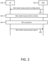
- FIG. 2 is a communication diagram illustrating an overlap in the UE side between an idle mode measurement activity and an SDT procedure in time domain.
- UE behaviors about idle mode measurement activity and SDT procedure are illustrated.
- the UE 210 may receive an idle mode measurement configuration from the serving RAN 220 (e.g., via broadcasting system information or via UE-specific control signaling, such as an RRCReconfiguration message).
- the serving RAN 220 e.g., via broadcasting system information or via UE-specific control signaling, such as an RRCReconfiguration message.
- the idle mode measurement configuration may include at least one of an idle/inactive measurement configuration or a logged measurement configuration, which instructs the UE 210 to measure DL channel conditions (e.g., DL-RSRP, DL-RSRQ, DL-RSSI) between the UE 210 and the serving RAN 220.
- the serving RAN 220 may be, for example, composed by one or more base stations/cells.
- the UE 210 may start an idle mode measurement activity (e.g., an idle/inactive measurement activity and/or a logged measurement activity) and start to count a timer to zero (e.g., a first timer (T330) associated with a logged measurement activity and/or a second timer (T331) associated with an idle/inactive measurement activity).
- a timer to zero e.g., a first timer (T330) associated with a logged measurement activity and/or a second timer (T331) associated with an idle/inactive measurement activity.
- T330 a first timer associated with a logged measurement activity
- T331 second timer associated with an idle/inactive measurement activity
- the UE 210 may release the stored idle mode measurement configuration and stop the idle mode measurement activity.
- the idle mode measurement results observed during action 202 e.g., "idle/inactive measurement results” and/or "logged measurement results”
- the UE 210 may be able to report the idle mode measurement reports (e.g., "idle/inactive measurement report” and/or "logged measurement report") to its serving RAN 220 later (e.g., in action 204).
- the UE may receive both of the idle/inactive measurement configuration and the logged measurement configuration simultaneously or at different timings. Therefore, the UE may implement both of the idle/inactive measurement activity and the logged measurement activity simultaneously and independently, and both of the measurement activities may (partially) overlap in time domain in the UE side.
- the UE may receive the idle mode measurement configuration (e.g., action 201) earlier than initiation of the SDT procedure (e.g., action 203). In some implementations, the UE may receive the idle mode measurement configuration (e.g., action 201) later than initiation of the SDT procedure (e.g., action 203) in time domain.
- the UE 210 may also be triggered (e.g., by the NAS layer or RRC layer of the UE 210) to implement an SDT procedure (e.g., action 203) while the UE 210 is implementing an idle mode measurement activity.
- the UE 210 may receive an idle mode measurement configuration (e.g., in action 201) while the UE 210 is implementing an SDT procedure.
- the idle mode measurement activity and the SDT procedure may overlap in time domain.
- some UEs may or may not be capable of implementing both of the idle mode measurement activity (e.g., action 202) and the SDT procedure (e.g., action 203) simultaneously.
- the mutual impacts between both of the idle mode measurement activity and the SDT procedure may need to be further addressed to make sure that a UE can work fluently when the UE is configured with both SDT configuration and idle mode measurement configuration, no matter whether the UE is capable of implementing both simultaneously.
- the idle mode measurement activity is shown to be triggered earlier than the SDT procedure.
- the sequence of the idle mode measurement activity and the SDT procedure is not limited in the present disclosure.
- the SDT procedure may be triggered earlier than the idle mode measurement activity.
- a UE stops a running first timer (e.g., T330) if the UE is implementing an SDT procedure.
- the UE stops/postpones/suspends the logged measurement activity during the SDT procedure.
- the UE may firstly receive a logged measurement configuration from the serving RAN of the UE, which may include an initial value (e.g., loggingDuration ) of the first timer (e.g., T330).
- the UE may configure the first timer (e.g., T330) in the UE side (e.g., in the RRC entity of the UE) by setting the initial value of the first timer (e.g., T330) (e.g., as the received loggingDuration ). Then, the UE may start to implement logged measurement and start to count the first timer (e.g., T330) to zero. The UE may maintain the logged measurement activity while the first timer (e.g., T330) is counting.
- the first timer e.g., T330
- the UE may stop the logged measurement activity and release the stored logged measurement configuration.
- the running first timer e.g., T330
- the logged measurement results measured by the UE during the logged measurement activity may still be kept by the UE, and then the UE may report to the serving RAN next time while the UE re-connects to the serving RAN.
- the UE may re-start and recount the stopped or expired first timer (e.g., T330), which may be stopped by the UE while the SDT procedure is initiated, after the SDT procedure terminates.
- the stopped or expired first timer e.g., T330
- the UE may keep counting the first timer (e.g., T330) even during an SDT procedure (e.g., CG-SDT or RA-SDT procedure). In some implementations, the UE may keep implementing the logged measurement activity even during an SDT procedure. In some other implementations, the UE may stop implementing the logged measurement activity even the first timer (T330) is counting during the SDT procedure.
- T330 the first timer
- the first timer (e.g., T330) may be counted to zero during an SDT procedure, and then the UE may release the stored logged measurement configuration during the SDT procedure. However, in this case, the UE may still keep the stored logged measurement results even the logged measurement configuration is released (e.g., during the SDT procedure).
- the UE may stop performing the logging measurement during the SDT procedure (which may include the subsequent data exchange during the SDT procedure) if the first timer (e.g., T330) is stopped.
- the logging measurement may not be impacted by the active SDT procedure (and the subsequent data exchange during the SDT procedure); therefore, the first timer (e.g., T330) may be still counting during the SDT procedure.
- the loggingDuration may be re-configured by the serving cell during an SDT procedure (e.g., by receiving an updated LoggedMeasurementConfiguration ).
- the UE may stop the existing counting first timer (e.g., T330) immediately (if it is running) once after receiving the updated LoggedMeasurementConfiguration.
- the UE may re-start the first timer (e.g., T330) by setting an initial value thereof based on the configured loggingDuration in the updated LoggedMeasurementConfiguration.
- the first timer e.g., T330
- the UE may implement the logged measurement based on the (updated) LoggedMeasurementConfiguration without being impacted by the SDT procedure.
- the UE may receive an updated LoggedMeasurementConfiguration during an SDT procedure.
- the UE may not implement the logged measurement based on the (updated) LoggedMeasurementConfiguration until (or unless) the SDT procedure is terminated.
- the UE may restart the first timer (e.g., T330) and apply the updated logged measurement configuration after the SDT procedure is terminated.
- the UE may not be configured with any logged measurement configuration before the UE initiates the SDT procedure, and the UE may receive a first logged measurement configuration during the SDT procedure.
- the UE may stop a running second timer (e.g., T331) if the UE is implementing the SDT procedure.
- a running second timer e.g., T331
- the UE may re-start and recount the stopped second timer (e.g., T331) after the SDT procedure terminates.
- the stopped second timer e.g., T331
- the UE may keep counting the second timer (e.g., T331) even during an SDT procedure (e.g., CG-SDT or RA-SDT procedure).
- an SDT procedure e.g., CG-SDT or RA-SDT procedure.
- the UE also stops performing the idle/inactive measurement during the SDT procedure (which may include the subsequent data exchange during the SDT procedure) if the second timer (e.g., T331) is stopped (e.g., during the SDT procedure).
- the second timer e.g., T331
- the UE may also stop performing the idle/inactive measurement during the SDT procedure (which may include the subsequent data exchange during the SDT procedure) when the second timer (e.g., T331) is still counting (e.g., during the SDT procedure).
- the activated idle/inactive measurement activity may not be impacted by the active SDT procedure (and the subsequent data exchange during the SDT procedure) and the second timer (e.g., T331) may be still running during the SDT procedure.
- the UE may receive an updated idle/inactive measurement configuration during an SDT procedure.
- the UE may (re)start to count the second timer (e.g., T331) by, for example, re-configuring the initial value based on the updated idle/inactive measurement configuration, only after the SDT procedure is terminated.
- the UE may not implement the idle/inactive measurement based on the (updated) idle/inactive measurement configuration until (or unless) the SDT procedure is terminated.
- the UE may restart the second timer (e.g., T331) and apply the updated idle/inactive measurement configuration after the SDT procedure is terminated.
- the UE may not be configured with any idle/inactive measurement configuration before the UE initiates the SDT procedure, and the UE may receive a first idle/inactive measurement configuration during the SDT procedure.
- an SDT procedure may be considered terminated while the UE receives a specific RRC message (e.g., RRCSetup message, RRCResume message, RRCRe-establishment message, etc.) from the serving RAN to terminate the running SDT procedure, or while the SDT failure (detection) timer associated with the running SDT procedure is counted to zero.
- a specific RRC message e.g., RRCSetup message, RRCResume message, RRCRe-establishment message, etc.
- SRB1/SRB2 signaling enhancements during an SDT procedure are described below.
- Some DL/UL control signaling may be transmitted via SRB1/SRB2 and it is observed that the SRB 1/SRB2 may be resumed during an SDT procedure.
- the DL/UL control signaling which may be (or may not be) transmitted during an SDT procedure is also discussed.
- a UE may be allowed to transmit a specific RRC/NAS signaling to the serving RAN via the SRB1/SRB2 automatically/implicitly (e.g., being pre-defined in technical specification) during an SDT procedure (e.g., while the UE is still staying in the RRC inactive state and the configured SDT failure detection timer is still running/active).
- a specific RRC/NAS signaling to the serving RAN via the SRB1/SRB2 automatically/implicitly (e.g., being pre-defined in technical specification) during an SDT procedure (e.g., while the UE is still staying in the RRC inactive state and the configured SDT failure detection timer is still running/active).
- the serving RAN e.g., serving cell/camped cell/selected cell/anchor cell of the UE
- the serving RAN may be allowed/enabled to transmit at least one specific RRC/NAS signaling to the UE via the SRB1/SRB2 automatically/implicitly (e.g., being pre-defined in technical specification) during an SDT procedure (e.g., while the UE is still staying in the RRC inactive state and the configured SDT failure detection timer is still running/active).
- the UE may receive explicit control signaling (e.g., UE-specific RRC signaling) from its serving RAN to enable/allow/configure the UE to transmit one or more specific signaling even while the SRB 1/SRB2 is resumed for the SDT procedure.
- explicit control signaling e.g., UE-specific RRC signaling
- the specific RRC/NAS signaling may include, but not be limited to, any combination of a CounterCheck message, a CounterCheckResponse message, a DLInformationTransfer message, a ULInformationTransfer message, a FailureInformation message, an IABOtherInformation message, a LocationMeasurementIndication message, a LoggedMeasurementConfiguration message, an RRCReconfiguration message, an RRCReconfigurationComplete message, a SecurityModeCommand message, a UEAssistanceInformation message, a UeinformationRequest message, a UeinformationResponse message, and a DedicatedSIBRequest message.
- the signaling associated with SRB2 e.g., the signaling which is transmitted via SRB2
- the serving cell may explicitly indicate which signaling is allowed for SDT and which signaling is not.
- the SRB 1 may be implicitly/directly allowed to be resumed/activated for SDT if at least the SRB2 or any DRB is activated for SDT.
- the signaling associated SRB1 e.g., the signaling which can be transmitted via SRB1
- the serving cell may explicitly indicate which signaling is allowed for SDT and which signaling is not.
- the UE may not be allowed or may be disabled/disallowed/configured not to transmit the specific RRC/NAS signaling to the serving RAN via the SRB 1/SRB2 automatically/implicitly (e.g., being pre-defined in technical specification) during the SDT procedure (e.g., while the UE is still staying in the RRC inactive state, and the configured SDT failure detection timer is still running/active).
- the serving RAN e.g., serving cell/camped cell/selected cell/anchor cell of the UE
- the serving RAN may not be allowed or may be disabled/disallowed to transmit the specific RRC/NAS signaling to the UE via the SRB1/SRB2 automatically/implicitly (e.g., being pre-defined in technical specification) during the SDT procedure (e.g., while the UE is still staying in the RRC inactive state and the configured SDT failure detection timer is still running/active).
- the UE may not expect to receive the specific RRC/NAS signaling (which is disabled to be transmitted during the active SDT procedure) during the SDT procedure.
- the UE may receive explicit control signaling (e.g., UE-specific RRC signaling) from its serving RAN to disable/disallow the UE to transmit one or more specific signaling even while the SRB1/SRB2 is resumed for the SDT procedure.
- explicit control signaling e.g., UE-specific RRC signaling
- the UE may be configured (e.g., via explicit signaling, such as the RRCReconfiguration message or the RRCRelease message, or within the SDT configuration) to be allowed/disallowed (or to be enabled/disabled) to transmit the specific RRC/NAS signaling to the serving RAN via the SRB1/SRB2 during the SDT procedure (e.g., while the UE is still staying in the RRC inactive state and the configured SDT failure detection timer is still running/active).
- explicit signaling such as the RRCReconfiguration message or the RRCRelease message, or within the SDT configuration
- the UE may be configured (e.g., via explicit signaling, such as the RRCReconfiguration message or the RRCRelease message, or within the SDT configuration) to be allowed/disallowed (or to be enabled/disabled) to transmit the specific RRC/NAS signaling to the serving RAN via the SRB1/SRB2 during the SDT procedure (e.g
- the serving RAN may transmit one or more DL control signaling to enable/disable (or allow/disallow) the UE to transmit a specific RRC/NAS signaling to the serving RAN via the SRB1/SRB2 during the SDT procedure (e.g., while the UE is still staying in the RRC inactive state and the configured SDT failure detection timer is still running/active).
- the DL control signaling to enable/allow/disable/disallow the specific RRC/NAS signaling exchange during the SDT procedure may be transmitted by the serving Cell via broadcasting system information or via UE-specific RRC signaling (e.g., RRCRelease message or RRCReconfiguration message) or within the SDT configuration.
- UE-specific RRC signaling e.g., RRCRelease message or RRCReconfiguration message
- the UE may only transmit the RRC/NAS signaling which is enabled/allowed to be exchanged during the SDT procedure by the serving RAN. In other words, the UE may not expect to receive the specific RRC/NAS signaling (which is disabled/disallowed to be transmitted during the active SDT procedure) during the SDT procedure.
- a specific RRC/NAS signaling may be associated with a default setting about whether the specific RRC/NAS signaling is allowed/disallowed/enabled/disabled to be exchanged during the SDT procedure.
- the UE may decide whether to transmit the specific RRC/NAS signaling based on the default setting.
- the source of the default setting may include at least one of: 1) a pre-installation in the memory module or USIM in the UE side, 2) a currently stored (e.g., RRC/SDT) configuration which the UE has received while the UE is still staying in the RRC connected state, or 3) broadcasting system information.
- the UE may be configured/enabled/allowed to transmit the RRC/NAS signaling to the anchor cell (e.g., the serving cell which (re)configures the SDT configuration) only.
- the anchor cellBS of a UE may be the cell/BS which stores the UE's inactive context/AS security and maintains the UE's connection with the core network (e.g., N1 interface).
- the UE may not be allowed/triggered/configured to transmit the RRC/NAS signaling with a non-anchor cell. That is, an RRC/NAS signaling may not be transmitted by a UE to its serving cell while the serving cell is a non-anchor cell to the UE. In some implementations, the UE may not resume the SRB2 with the serving cell (e.g., during the SDT procedure) while the serving cell is not the anchor cell to the UE.
- the UE may be pre-defined (e.g., in the 3GPP technical specification) about which UL control signaling could be transmitted by the UE (e.g., via the resumed SRB1/SRB2) during an SDT procedure while the SRB1/SRB2 is resumed for the SDT procedure.
- the UE may be (pre-)configured (e.g., via explicit signaling/explicit configuration from the serving RAN) about which UL control signaling could be transmitted by the UE (via the resumed SRB1/SRB2) during an SDT procedure while the SRB1/SRB2 is resumed for the SDT procedure.
- the UE may be further (pre-)configured about which procedures that the UE/serving cell could initiate during the SDT procedure.
- the RRC/NAS signaling exchange procedure triggered by the UE or by the serving RAN/serving CN of the UE during a running SDT procedure may be interrupted by an SDT failure event (which is described below).
- the pending RRC/NAS message in the UE side may be released with an SDT failure condition (e.g., the MAC buffer associated with the SRB1/SRB2 may be flushed/dropped/released after the SDT failure event is announced/considered by the UE).
- the pending RRC/NAS message may be re-transmitted by the UE after the SDT failure event happens (e.g., the UE may start a non-SDT procedure, such as an RRC resume procedure, to request to move to the RRC connected state after the SDT failure event. Then, the UE may (re)transmit the pending RRC/NAS message after the UE moves to the RRC connected state). In some implementations, the UE may re-start another SDT procedure to re-transmit the pending RRC/NAS message to the serving RAN/CN again.
- a non-SDT procedure such as an RRC resume procedure
- the RRC/NAS signaling exchange procedure triggered by the UE or by the serving RAN/serving CN of the UE during a running SDT procedure may be interrupted by at least one fallback event (which is described below) before the UE transmits any pending RRC/NAS message to the serving cell (e.g., when the UE receives a fallback instruction from the serving cell or the UE initiates a fallback mechanism automatically).
- the pending RRC/NAS message may be released with the SDT fallback condition (e.g., the MAC buffer associated with the SRB1/SRB2 may be flushed/dropped/released after the SDT fallback event is announced/considered by the UE).
- the pending RRC/NAS message may be re-transmitted by the UE after the SDT fallback event happens (e.g., the UE may fall back to a non-SDT procedure, such as an RRC resume procedure, to request to move to the RRC connected state after the SDT fallback event. Then, the UE may (re)transmit the pending RRC/NAS message after the UE moves to the RRC connected state). In some implementations, the UE may fall back to another SDT procedure (e.g., from a failed CG-SDT procedure to an RA-SDT procedure), and then the UE may re-transmit the pending RRC/NAS message to the serving RAN/CN again. It is noted that the pending RRC/NAS signaling may be an initial Hybrid Automatic Repeat reQuest (HARQ) transmission or a HARQ re-transmission in the HARQ protocols.
- HARQ Hybrid Automatic Repeat reQuest
- the network may transmit one or more CounterCheck messages to indicate the current COUNT Most Significant Bit (MSB) values associated with each Data Radio Bearer (DRB), to request the UE to compare these to its COUNT MSB values, and to report the comparison results to the network.
- MSB Most Significant Bit
- DRB Data Radio Bearer
- the DRB in the CounterCheck message may only include the Radio Bearers (e.g., DRB(s)/SRB(s)) which are configured/enabled/allowed to be activated/resumed in an SDT procedure; therefore, only the pending data in these DRB(s)/SRB(s) or logical channels associated with these DRB(s) may be exchanged during the SDT procedure.
- the DRB(s)/SRB(s) which are not allowed/enabled for data exchange during SDT procedures may not be included in the CounterCheck message while the CounterCheck message is transmitted during an SDT procedure.
- the DRB(s)/SRB(s) not configured/activated/resumed for SDT may be considered to be unused (e.g., by assuming the COUNT value as "0") in the CounterCheck message (e.g., transmitted by the serving Cell) and/or in the CounterCheckResponse message.
- the DRB(s)/SRB(s) not configured/activated/resumed for SDT may not be indicated by the serving cell in the CounterCheck message. In this case, the UE may not need to reply with the COUNT value of these DRBs in the CounterCheckResponse message.
- the CounterCheck message indicated during the SDT procedure may include all of the DRB(s)/SRB(s) configured in the UE side (e.g., no matter whether the DRB/SRB is activated/de-activated/resumed/suspended) during the SDT procedure.
- the UE may reply with a CounterCheckResponse message to the serving cell.
- the CounterCheck message delivered during the SDT procedure may still cover all of the DRB(s)/SRB(s) configured in the UE side (e.g., no matter whether the DRB/SRB is suspended or activated/resumed for SDT), which means that the COUNT value of all of the DRBs/SRBs in the UE side may be indicated by the serving cell.
- the CounterCheckResponse message delivered during the SDT procedure may also cover at least one DRB/SRB configured in the UE side (e.g., no matter whether the DRB/SRB is suspended or activated/resumed for SDT).
- the UE may reply with the COUNT value (stored in the UE side) associated with a DRB/SRB while the MSBs of the COUNT value stored in the UE side associated with one DRB/SRB (which is activated/resumed by the UE during the SDT procedure) is different from the value indicated by the serving RAN via the CounterCheck message (to the same DRB/SRB).
- the UE may reply with the COUNT value of a DRB/SRB no matter whether the DRB/SRB is suspended or activated/resumed during the SDT procedure, which means that the UE may check the COUNT value of a suspended DRB during the counter checking procedure initiated by the serving cell during an SDT procedure.
- the UE in response to the CounterCheck message, for each DRB/SRB that is included in the drb-CountMSB-InfoList in the CounterCheck message and that is not established by the UE, the UE may include the DRB/SRB in the drb-CountInfoList in the CounterCheckResponse message by including the drbIdentity, the count-Uplink, and the count-Downlink with the MSBs set identical to the corresponding values in the drb-CountMSB InfoList and the least significant bits (LSBs) set to zero.
- LSBs least significant bits
- the counter check procedure may be interrupted by an SDT failure event.
- the SDT failure detection timer may be stopped before the UE transmits the CounterCheckResponse message to the serving cell.
- the pending CounterCheckResponse message may be released with the SDT failure condition (e.g., the MAC buffer associated with the SRB1/SRB2 may be flushed/dropped/released after the SDT failure event is announced/considered by the UE).
- the pending CounterCheckResponse message may be re-transmitted by the UE after the SDT failure event happens (e.g., the UE may start a non-SDT procedure, such as an RRC resume procedure, to request to move to the RRC connected state after the SDT failure event. Then, the UE may (re)transmit the CounterCheckResponse message after the UE moves to the RRC connected state). In some implementations, the UE may re-start another SDT procedure to re-transmit the CounterCheckResponse message to the serving RAN/CN again.
- a non-SDT procedure such as an RRC resume procedure
- the counter check procedure may be interrupted by the fallback mechanism while a fallback event happens before the UE transmits the CounterCheckReponse message to the serving cell (e.g., when the UE receives a fallback instruction from the serving cell or the UE initiates a fall back mechanism automatically).
- the pending CounterCheckResponse message may be released with the SDT fallback condition (e.g., the MAC buffer associated with the SRB1/SRB2 may be flushed/dropped/released after the SDT fallback event is announced/considered by the UE).
- the pending CounterCheckResponse message may be re-transmitted by the UE after the SDT fallback event happens (e.g., the UE may fall back to a non-SDT procedure, such as an RRC resume procedure, to request to move to the RRC connected state after the SDT fallback event. Then, the UE may (re)transmit the CounterCheckResponse message after the UE moves to the RRC connected state). In some implementations, the UE may fall back to another SDT procedure (e.g., from a failed CG-SDT procedure to an RA-SDT procedure), and then the UE may re-transmit the CounterCheckResponse message to the serving RAN/CN again.
- a non-SDT procedure such as an RRC resume procedure
- the DLInformationTransfer message is used for the downlink transfer of NAS dedicated information and timing information for the 5G internal system clock.
- the DLInformationTransfer may be transmitted via an SRB2 or an SRB1 (only if the SRB2 is not established yet or the SRB2 is not resumed for SDT).
- the serving cell may not be allowed to transmit the NAS signaling during the SDT procedure, and/or the UE may not expect a NAS signaling exchange during the SDT procedure.
- the UE may still be allowed to transmit the NAS signaling via the SRB1 if only SRB1 is configured to be activated for SDT (and SRB2 is not established or is not resumed for SDT).
- the serving cell may transmit the DLInformationTransfer message to the UE only via the SRB2 during the SDT procedure.
- the ULInformationTransfer message is used for the uplink transfer of NAS or non-3GPP dedicated information.
- the UE may only be allowed/enabled/configured to transmit the NAS signaling during an SDT procedure. In contrast, the UE may not be allowed/enabled/configured to transmit non-3GPP dedicated information during the SDT procedure.
- the ULInformationTransfer may be transmitted via an SRB2 or an SRB1 (only if SRB2 is not established yet or the SRB2 is not resumed for SDT).
- the UE may not be allowed to transmit the NAS signaling to the serving RAN during the SDT procedure, and/or the UE may not expect a NAS signaling exchange during the SDT procedure. In some implementations, the UE may still be allowed to transmit the NAS signaling via the SRB1 if only SRB1 is configured to be activated for SDT (e.g., no active/resumed SRB2 for SDT).
- the UE may transmit the ULInformationTransfer message to the serving cell only via the SRB2 during the SDT procedure.
- the FailureInformation message is used to inform the network about a failure detected by the UE.
- the FailureInformation may be transmitted by the UE (to the serving RAN) only via an SRB1.
- the IABOtherInformation message is used by Integrated Access and Backhaul-Mobile Termination (IAB-MT), which initiates an SDT procedure to request the network to allocate IP addresses for the collocated Integrated Access and Backhaul-Distributed Unit (IAB-DU) or to inform the network about IP addresses allocated to the collocated IAB-DU.
- IAB-MT may be enabled/configured to transmit an IABOtherInformation message via an SRB1 while the IAB-MT initiates an SDT procedure.
- the IABOtherInformation message may be transmitted by the UE (e.g., to the serving RAN) only via the SRB1.
- a UE e.g., an IAB-MT
- the UE may either start or stop location-related measurement which requires measurement gaps.
- the UE may not transmit LocationMeasurementIndication to the serving cell (e.g., via the resumed SRB1) during the SDT procedure (during the SDT procedure and the subsequent data transmission/reception procedure happens during the same SDT procedure).
- the UE may transmit LocationMeasurementIndication message (e.g., via the resumed SRB1) to inform that the UE may not be able to implement the following subsequent data exchange during the SDT procedure.
- the UE may transmit the LocationMeasurementIndication message to indicate that the UE may not be able to access one or more uplink configured grants for CG-SDT procedure for a time period, which may be presented by the IE LocationMeasurementInfo in the LocationMeasurementIndication message.
- the LoggedMeasurementConfiguration message is used to configure the UE to perform logging of measurement results while the UE is staying in the RRC idle state or the RRC inactive state.
- the LoggedMeasurementConfiguration message is used to transfer the logged measurement configuration for network performance optimization.
- the serving cell may transmit the LoggedMeasurementConfiguration message to the UE (e.g., via the resumed SRB1) during the SDT procedure (e.g., during the subsequent DL packet transmission before the CG-SDT/RA-SDT procedure is terminated).
- the UE may configure/update/modify/release its own stored logged measurement configuration based on the received LoggedMeasurementConfiguration.
- the UE may (start to) implement the logged measurement based on the received LoggedMeasurementConfiguration.
- the UE may update the stored LoggedMeasurementConfiguration directly after receiving the updated LoggedMeasurementConfiguration configuration during the SDT procedure.
- the UE may be triggered to implement logged measurement immediately.
- the UE may not expect the network to transmit the LocationMeasurementIndication message to the UE during the SDT procedure.
- the serving cell may transmit one or more RRCReconfiguration messages during the SDT procedure, which re-configures the UE context (e.g., UE inactive context stored in the UE side) and/or SDT configuration/idle or inactive mode packet transmission configuration during the SDT procedure.
- the UE may reply with an RRCReconfigurationComplete message to the serving cell (e.g., during the same SDT procedure) if the UE could comply/implement all of the received instructions in the received RRCReconfiguration message without error.
- an RRC Reconfiguration Failure event may happen if the UE could not implement any part of instructions (or Ies) in the RRCReconfiguration message.
- the UE may keep the UE's original configuration (e.g., original SDT configuration and/or original UE inactive AS context) and then reply with an RRCReconfigurationFailure message to the serving cell.
- the SDT procedure may still be active, all the running timers (associated with the SDT procedure) may be still counting/active, and the pending UL data/(AS/NAS) control signaling may still be kept in the buffer without being impacted by the (RRC) Reconfiguration Failure event.
- the UE may still stay in the RRC inactive state when the RRC Reconfiguration Failure event happens during an SDT procedure.
- the UE may not reply the RRCReconfigurationFailure message to the UE.
- the UE may move to the RRC idle state.
- the UE may initiate one random access procedure to transmit an RRCSetupRequest message to the serving cell (e.g., via MSGA/MSG3 delivery during a 2-step/4-step random access procedure to try to connect with the serving RAN again). Therefore, the running SDT procedure may be interrupted by the RRC Reconfiguration Failure event.
- the RRC Reconfiguration Failure event may be considered as one event for the UE to trigger an SDT failure event.
- the stored SDT configuration and UE inactive AS context may be cleared/released/dropped.
- the UE may not reply the RRCReconfigurationFailure message to the UE.
- the UE may stay in the RRC inactive state, but the SDT procedure may also be interrupted by the Reconfiguration Failure event. Then, the UE may initiate a random access procedure to transmit an RRCResumeRequest message to the serving cell (e.g., to try to resume its RRC connection with the serving RAN again based on the stored UE inactive AS context).
- the UE may stay in the RRC inactive state, but the SDT procedure may also be interrupted by the Reconfiguration Failure event. Then, the UE may initiate a random access procedure to transmit an RRCRe-establishmentRequest message to the serving cell (e.g., via MSGA or MSG3 during a 2-step/4-step RA procedure to try to reestablish its RRC connection with the serving RAN again based on the stored UE inactive AS context).
- the serving cell e.g., via MSGA or MSG3 during a 2-step/4-step RA procedure to try to reestablish its RRC connection with the serving RAN again based on the stored UE inactive AS context.
- the UE may modify/update/release all or a subset of the stored UE inactive context based on the received RRCReconfiguration message. In some implementations, the UE may modify/update the stored SDT configuration/idle or inactive mode packet transmission configuration based on the received RRCReconfiguration message.
- only the SDT configuration could be re-configured by the serving cell while an RRCReconfiguration message is transmitted during an SDT procedure.
- the serving cell may not be able to modify/update/release all or a subset of stored UE inactive context by transmitting the RRCReconfiguration message during the SDT procedure.
- an RRC Reconfiguration procedure trigged during an SDT procedure may be interrupted by an SDT failure event.
- the SDT failure detection timer may expire or may be stopped before the UE transmits the RRCReconfigurationComplete message to the serving cell.
- the UE may consider the interruption event as one of the RRC Reconfiguration Failure events, and then the UE may apply at least one of the proposed mechanisms about the RRC Reconfiguration Failure event.
- the RRC Reconfiguration procedure may be interrupted by the fallback mechanism while a fallback event happens before the UE transmits the RRCReconfigurationComplete message to the serving cell (e.g., the UE receives a fallback instruction from the serving cell or the UE initiates a fallback mechanism automatically).
- the UE may consider the fallback event as one of the RRC Reconfiguration Failure events, and then the UE may apply at least one of the proposed mechanisms about the RRC Reconfiguration Failure event.
- the network may not transmit a SecurityModeCommand message to the UE during an SDT procedure.
- the network may transmit the SecurityModeCommand message to the UE during the SDT procedure (e.g., while only SRB1 is resumed during the SDT procedure, but the network may want to (re)configure the following SRB2/DRB(s) during the SDT procedure).
- the UE may start to derive AS security keys (e.g., based on the Section 5.3.4.3 in TS 38.331 v16.5.0). Then, the UE may reply with a SecurityModeComplete message or a SecurityModeFailure message also during the SDT procedure. In some implementations, the UE may consider that the SDT procedure fails and may move to the RRC idle state if a Security Mode Failure event happens.
- the UE may keep the UE's original configuration (e.g., UE may continue using the stored NAS/AS security configuration used prior to the reception of the SecurityModeCommand message) and then reply with a SecurityModeFailure message to the serving cell.
- the SDT procedure may still be active, all the running timers associated with the SDT procedure) may be still counting/active, and the pending UL data/(AS/NAS) control signaling may still be kept in the buffer without being impacted by the Security Mode Failure event.
- the UE may still stay in the RRC inactive state when the Security Mode Failure event happens during an SDT procedure.
- the UE may not reply with the SecurityModeFailure message to the serving cell.
- the UE may move to the RRC idle state.
- the UE may initiate a random access procedure to transmit an RRCSetupRequest message to the serving cell (e.g., via MSGA/MSG3 delivery during a 2-step/4-step random access procedure to try to connect with the serving RAN again).
- the running SDT procedure is interrupted by the Security Mode Failure event.
- the Security Mode Failure event may be considered as an event for the UE to trigger the SDT failure event.
- the stored SDT configuration (e.g., which may include the stored AS/NAS security configuration) and UE inactive AS context may be cleared/released/dropped.
- the UE may not reply with the SecurityModeFailure message to the serving cell.
- the UE may stay in the RRC inactive state, but the SDT procedure may also be interrupted by the Security Mode Failure event. Then, the UE may initiate a random access procedure to transmit an RRCResumeRequest message to the serving cell (e.g., to try to resume its RRC connection with the serving RAN again based on the stored UE inactive AS context).
- the UE may stay in the RRC inactive state, but the SDT procedure may also be interrupted by the Security Mode Failure event. Then, the UE may initiate a random access procedure to transmit an RRCRe-establishmentRequest message to the serving cell (e.g., via MSGA or MSG3 during a 2-step/4-step RA procedure to try to reestablish its RRC connection with the serving RAN again based on the stored UE inactive AS context).
- the serving cell e.g., via MSGA or MSG3 during a 2-step/4-step RA procedure to try to reestablish its RRC connection with the serving RAN again based on the stored UE inactive AS context.
- the Security Mode Command procedure trigged during an SDT procedure may be interrupted by an SDT failure event.
- the SDT failure detection timer may be stopped before the UE transmits the SecurityModeComplete message to the serving cell.
- the UE may consider the interruption event as a Secuity Mode Failure event and then the UE may apply at least one of the proposed mechanisms about the Security Mode Failure event.
- the Security Mode Command procedure may be interrupted by a fallback mechanism while a fallback event happens before the UE transmits the SecurityModeComplete message to the serving cell (e.g., the UE receives a fallback instruction from the serving cell, or the UE initiates a fallback mechanism automatically).
- the UE may consider the fallback event as a Security Mode Failure event, and then the UE may apply at least one of the proposed mechanisms about the Security Mode Failure event.
- the SidelinkUEinformationNR message is used for the indication of NR sidelink UE information to the network
- the SidelinkUEinformationEUTRA message is used for the indication of E-UTRA sidelink UE information to the network.
- the UE may transmit the SidelinkUEinformationNR message during the SDT procedure (e.g., via the resumed SRB1).
- the UE may not be allowed to transmit the SidelinkUEinformationNR message during the SDT procedure. In other words, the UE may be allowed to transmit the SidelinkUEinformationNR message only while the UE is staying in the RRC connected state.
- the UEAssistanceInformation message is used for the indication of UE assistance information to the network.
- the UE may transmit the SidelinkUEinformationNR message during the SDT procedure (e.g., via the resumed SRB1) in the UEAssistanceInformation message.
- the UE may transmit a ReleasePreference message (e.g., by configuring the preferredRRC-state-idle) in the UEAssistanceInformation message.
- the UE may transmit in-device coexistence (IDC) information (idc-assistance information) in the UEAssistanceInformation message to solve the IDC issue (e.g., caused by the SDT procedure).
- IDC in-device coexistence
- the UE may transmit the UEAssistanceInformation message to the serving cell during the SDT procedure only while the UE receives the RRCReconfiguration message from the serving cell during the same SDT procedure.
- the UE may not be allowed (or configured) to transmit the UEAssistanceInformation message during the SDT procedure. In other words, the UE may be allowed to transmit the UEAssistanceInformation message only while the UE is staying in the RRC connected state.
- the serving cell may transmit a UEInformationRequest message to the UE to report during the SDT procedure.
- the UE may reply with a UEInformationResponse message to the serving cell also during the same SDT procedure.
- the UE may reply with an available 'measResultIdleEUTRA' and/or 'measResultIdleNR' in the VarMeasIdleReport, which may be transmitted by the UE within the UEInformationResponse message.
- the UE may record the failed random access procedures which are triggered for RA-SDT procedures in the VarRA-Report (e.g., stored in the ra-ReportList within the VarRA-Report ).
- the UE may record the radio link failure (RLF) event happens during the running CG-SDT/RA-SDT procedure and/or previous SDT procedures.
- RLF radio link failure
- the UE may record the RLF event while the (e.g., Automatic Repeat request (ARQ)) re-transmissions within an RLC entity reaches the pre-defined maximum number during an SDT procedure.
- ARQ Automatic Repeat request
- the UE may also record the beam failure recovery failure event happens during an SDT procedure.
- the UE may also record the T310 expiry event while: 1) a T310 is started upon detecting physical layer problems for the serving cell during the SDT procedure (e.g., upon receiving N310 consecutive out-of-sync indications from the lower layers during a CG-SDT/RA-SDT procedure), then 2) the T310 expires (e.g., during the SDT procedure), and a radio link failure event may be decided by the UE.
- the UE may transmit the UEInformationResponse message only via the SRB2. In other words, during the SDT procedure, the UE may not transmit the UEInformationResponse message with the logMeasReport if the SRB2 is not resumed by the UE (e.g., based on the SDT configuration from the serving cell) for the SDT procedure. In some implementations, the serving cell may not request the logMeasReport during an SDT procedure if the SRB2 is not resumed during the SDT procedure.
- the serving cell may request the logMeasReport during an SDT procedure only while the SRB2 is resumed to the UE.
- the UE may not expect the serving cell to request the logMeasReport during an SDT procedure if the SRB2 is not resumed.
- the UE may report the logMeasReport only after the UE moves back to the RRC connected state (e.g., based on the request/enquiry procedure instructed by the serving cell of the UE).
- the UE may transmit the UEInformationResponse message via the SRB 1 if the logMeasReport is included in the UEInformationResponse message. In some implementations, the UE may not transmit the logMeasReport within the UEInformationResponse message with other Ies if only the SRB1 is resumed at the UE side. In some cases, the UE may transmit the UEInformationResponse message but with empty data if only the logMeasReport is requested by the serving cell but the SRB2 is not resumed for the SDT procedure. In some cases, the UE may ignore/skip the UEInformationResponse message transmission if only the logMeasReport is requested by the serving cell but the SRB2 is not resumed for the SDT procedure.
- the UE may be allowed/enabled/configured to transmit a DedicatedSIBRequest message during an SDT procedure (e.g., during a CG-SDT procedure/RA-SDT procedure).
- the UE may configure a timer (e.g., T350) and count the timer (e.g., T350) to zero upon the UE transmits the DedicatedSIBRequest message with the requestedSIB-List and/or the requestedPosSIB-List.
- the timer e.g., T350
- the timer may be stopped if the running SDT failure detection timer associated with the active SDT procedure expires.
- the timer e.g., T350
- the timer may be stopped if the UE implements an SDT fallback mechanism (e.g., after receiving an SDT fallback instruction from the serving cell during an SDT procedure).
- the timer (e.g., T350) may be stopped if the SDT procedure is interrupted (e.g., when the UE re-selects to another cell during the SDT procedure). In some implementations, the timer (e.g., T350) may be stopped if the running SDT procedure is terminated (e.g., after the UE receives an RRCRelease message from the serving cell to terminate the running SDT procedure).
- the UE may be (pre-)configured/defined with a threshold for the maximum number of the DedicatedSIBRequest transmissions for an SDT procedure. For example, in a case that the UE is (pre)configured/(pre)defined with a maximum DedicatedSIBRequest transmission number of one, the UE may transmit at most one DedicatedSIBRequest message during one SDT procedure. In some implementations, the UE may set an accumulated number of the DedicatedSIBRequest transmissions (for an SDT procedure) to zero every time an SDT procedure is initiated, and the UE may be allowed to transmit the DedicatedSIBRequest message to the serving cell during the SDT procedure while the accumulated DedicatedSIBRequest transmission number is still under the threshold.
- the UE may add the accumulated number of the DedicatedSIBRequest transmissions by 1 every time when a DedicatedSIBRequest message is transmitted during the SDT procedure.
- the UE may not be allowed to transmit the DedicatedSIBRequest message in the SDT procedure anymore while the accumulated number of the DedicatedSIBRequest transmission reaches (or is more than) the given threshold.
- the UE may not start the timer (e.g., T350) after the UE transmits the DedicatedSIBRequest message during the SDT procedure.
- the UE may re-set the accumulated number of the DedicatedSIBRequest transmission to zero and as such the UE may be able to transmit the DedicatedSIBRequest message to the serving RAN again in the next SDT procedure.
- the UE may not transmit the DedicatedSIBRequest message during an SDT procedure, and UE may not be allowed/enabled to transmit the DedicatedSIBRequest message during the SDT procedure.
- the UE may be (pre-)configured/defined not to transmit the DedicatedSIBRequest message during an SDT procedure.
- the UE may be limited to deliver the DedicatedSIBRequest message only for a specific purpose (e.g., only for Positioning SIB (PosSIB) or only for one or more specific SIBs).
- the serving cell may transmit any combinations of the requested SIB(s) during the same SDT procedure via a UE-specific DL control signaling (e.g., a DL-RRC signaling).
- a UE-specific DL control signaling e.g., a DL-RRC signaling
- the DedicatedSIBRequest procedure (e.g., trigged during an SDT procedure) may be interrupted by an SDT failure event.
- the SDT failure detection timer may be stopped after the UE transmits the DedicatedSIBRequest message to the serving cell.
- the running timer (e.g., T350) may be stopped with the SDT failure event.
- the DedicatedSIBRequest procedure may be interrupted by a fallback mechanism while a fallback event happens after the UE transmits the DedicatedSIBRequest message to the serving cell (e.g., the UE receives a fallback instruction from the serving cell, or the UE initiates a fallback mechanism automatically).
- the running timer e.g., T350
- T350 the running timer
- the UE may not transmit MeasurementReport to the serving cell (e.g., via the resumed SRB 1) during an SDT procedure.
- the UE may not transmit SCGFailureInformation / SCGFailureInformationEUTRA to the serving cell (e.g., via the resumed SRB1) during an SDT procedure.
- the UE may not expect the serving cell to transmit MobilityFromNRCommand to the UE (e.g., via the resumed SRB 1) during an SDT procedure.
- the UE may not expect the serving cell to transmit a UECapabilityEnquiry message to the UE (e.g., via the resumed SRB1) during an SDT procedure.
- the UE may ignore an unintended DL signaling (e.g., DL signaling that the UE does not expect the serving cell would transmit during an SDT procedure).
- an unintended DL signaling e.g., DL signaling that the UE does not expect the serving cell would transmit during an SDT procedure.
- the UE may consider an RRC connection failure event happens. After an RRC connection failure event is identified by the UE, in some implementations, the UE may initiate an RRC re-establishment procedure (e.g., by transmitting an RRC(Connection)Re-establishmentRequest message to the serving cell during an initiated 2-step/4-step random access procedure). In some implementations, the UE may move to the RRC idle state and initiate an RRC establishment procedure (e.g., by transmitting an RRC(Connection)SetupRequest message to the serving cell during an initiated 2-step/4-step random access procedure).
- RRC re-establishment procedure e.g., by transmitting an RRC(Connection)Re-establishmentRequest message to the serving cell during an initiated 2-step/4-step random access procedure.
- the stored UE inactive context may be modified based on the UE-specific DL control signaling transmitted by the serving cell.
- the RRC/NAS signaling described above may also be exchanged between base stations in the serving RAN (e.g., via inter-node signaling).
- the UE may be configured with an SDT configuration from an anchor cell/BS (e.g., Cell#1BS#1, which instructs the UE to move to the RRC inactive state via an RRCRelease message and also enables the UE to implement SDT procedures during the RRC inactive state), then the UE may re-select another serving cell due to an idle mode mobility event (e.g., cell (re)selection procedure). Then, the UE may initiate an SDT procedure with the serving cell/BS (e.g., Cell#2/BS#2).
- an anchor cell/BS e.g., Cell#1BS#1
- an UE e.g., Cell#1BS#1
- an idle mode mobility event e.g., cell (re)selection procedure
- the UE may initiate an SDT procedure with the serving cell/BS (
- the UE may additionally exchange any one of the indicated RRC/NAS signaling via SRB1/SRB2 (e.g., which may be resumed for the SDT procedure) within the airlink between the UE and the serving cell/BS (e.g., the Cell#2/BS#2). Then, the serving cell/BS may forward/translate the decoded/un-decoded/received RRC/NAS signaling to the anchor cell/BS.
- SRB1/SRB2 e.g., which may be resumed for the SDT procedure
- the anchor cell/BS may also generate one or more RRC/NAS signaling for the concerned UE and then deliver the generated signaling to the serving cell/BS via (wired/wireless) backhaul connections.
- the serving cell/BS may forward/relay the RRC/NAS signaling generated by the anchor cell/BS (e.g., Cell#1/BS#1) to the UE during the SDT procedure.
- the anchor cell/BS may be a New Radio (NR) cell (or an NR base station, such as gNB).
- the anchor cell/BS may be an E-UTRA cell (or an E-UTRA base station, such as eNB).
- the serving cell/BS may be an NR Cell (or an NR base station, such as gNB).
- the serving cell/BS may be an E-UTRA cell (or an E-UTRA base station, such as eNB). Therefore, the backhaul connections between the serving cell/BS and the anchor cell/BS may be an X2 interface/Xn interface/Integrated Access and Backhaul (IAB) connection.
- the core network (or at least one entity in the core network, such as Access and Mobility Management Function (AMF)) may involve in the RRC/NAS signaling exchange between the serving cell/BS and the anchor cell/BS.
- AMF Access and Mobility Management Function
- different neighbor cells may configure UEs differently with regards to whether SRB2 is allowed for SDT or not, and it may have an impact on the UE.
- the UE may have an active SDT procedure with a first cell, then an SDT failure event may happen (e.g., the UE re-selects to a second cell due to cell re-selection procedure). In this case, the UE may be triggered to re-start another SDT procedure with the second cell.
- the UE may have at least one pending Transport Block/packet which has multiplexed packets from DRB/SRB1 and SRB2, but the second cell may not support SRB2 resumption for SDT.
- the UE may start an RRC resume procedure rather than an SDT procedure, if there is any pending data of SRB2 (e.g., the pending data is received from the logical channel associated with SRB2) multiplexed with the data from other logical channels in the UE's buffer.
- the UE may drop/release/remove the pending Transport Blocks which have multiplexed data from SRB2 (or the UE may drop/release/remove all of the pending TBs, or the UE may move to the RRC idle state) if the mismatch condition (e.g., whether the SRB2 is allowed for SDT or not) happens between the last serving cell and the current serving cell.
- another mismatch that the first cell does not support SRB2 resumption for SDT, but the second cell supports it may not cause an issue for the UE/RAN.
- the mismatch condition may also happen in the same cell (e.g., the UE is implementing a unified access control (UAC) mechanism for the SDT procedure, and the UE is still barred from performing SDT during a backoff time period.
- the serving cell of the UE may modify the IE SRB2allowedforSDT during the backoff period before the UE starts a CG-SDT/RA-SDT procedure on the airlink).
- the cell/BS may modify the IE semi-persistently (e.g., change the SRB2allowedforSDT from 'true/allowed' to ⁇ false/notallowed', or vice versa) when a concerned UE is going to start an SDT procedure, or when an SDT procedure is ongoing, or when the UE wants to re-start a failed/interrupted SDT procedure with the same serving cell.
- the IE semi-persistently e.g., change the SRB2allowedforSDT from 'true/allowed' to ⁇ false/notallowed', or vice versa
- the UE may ignore (e.g., not to decode) the IE SRB2allowedforSDT and keep the SDT procedure active even if the IE has been modified by the serving cell.
- the SDT attempt is temporally barred, and the UE may start an RRC resume procedure (or an RRC establishment procedure), rather than an SDT procedure, with the same serving cell (after the cell re-configures the SRB2allowedforSDT from 'true' to ⁇ false') if there is any pending data of SRB2 multiplexed with the data from other logical channels in the UE's buffer.
- the UE may drop/release/remove the pending Transport Blocks which have multiplexed data from SRB2 (or the UE may drop/release/remove all of the pending TBs, or the UE may move to the RRC idle state) if the serving cell changes the IE of whether the SRB2 is allowed for SDT or not before the UE triggers an SDT procedure (e.g., via an MSGA/MSG1 delivery or via a UL-CG access).
- SDT procedure e.g., via an MSGA/MSG1 delivery or via a UL-CG access.
- the proposed mechanism about the SRB2 IE modification on the serving cell/neighbor cell may not be limited to the SRB2 change scenario but may also be applicable to other scenarios that the serving cell/neighbor changes any part of broadcasting SDT configuration while an SDT procedure is active/barred/waiting to be (re)started.
- the SDT configuration may be, for example, a CG-SDT configuration and/or an RA-SDT configuration.
- NR supports the RRC inactive state and UEs with infrequent (periodic and/or non-periodic) data transmission are generally maintained by the network in the RRC inactive state.
- the RRC inactive state doesn't support data transmission.
- the UE has to resume the connection (e.g., move to the RRC connected state) for any DL reception and/or UL data transmission.
- Connection setup and subsequent releasing to the RRC inactive state happen for each data transmission regardless of how small and infrequent the data packets are. This results in unnecessary power consumption and signaling overhead.
- Signaling overhead due to transmission of small data packets is a general problem and will become a critical issue as the number of UEs increase in NR, not only for network performance and efficiency, but also for UE battery performance.
- any device that has intermittent small data packets in an inactive state will benefit from enabling small data transmission in the inactive state.
- RRC inactive state is a state where a UE remains in Connection Management (CM) -Connected and can move within an area configured by NG-RAN (the RNA) without notifying NG-RAN.
- CM Connection Management
- NG-RAN the RNA
- the last serving gNB node keeps the UE context and the UE-associated NG connection with the serving AMF and UPF.
- the RRC inactive state may support at least one of the following functions: PLMN selection, broadcast of system information, cell re-selection mobility, paging initiated by NG-RAN (RAN paging), RAN-based notification area (RNA) managed by NG- RAN, DRX for RAN paging configured by NG-RAN, 5GC - NG-RAN connection (both Control/User (C/U)-planes) established for UE, the UE AS context stored in NG-RAN and the UE, NG-RAN knows the RNA which the UE belongs to, and/or, etc.
- the UE identity "I-RNTI" may be used to identify the UE context in the RRC inactive state.
- the I-RNTI provides the new NG-RAN node a reference to the UE context in the old NG-RAN node. How the new NG-RAN node is able to resolve the old NG-RAN ID from the I-RNTI is a matter of proper configuration in the old and new NG-RAN node.
- UE Inactive AS Context is stored when the connection is suspended (e.g., when the UE is in the RRC inactive state) and restored when the connection is resumed (e.g., when the UE is transited from the RRC inactive state to the RRC connected state).
- FIG. 3 is a state diagram illustrating a state machine in NR according to an example implementation of the present disclosure.
- a UE has only one RRC state in NR at one time.
- the suspension of the RRC connection is initiated by the network.
- the UE in the RRC connected state e.g., RRC_CONNECTED
- the UE in the RRC connected state stores the UE Inactive AS context and configurations received from the network, and transits to the RRC inactive state.
- the UE may release the SCG configuration upon initiating an RRC connection resume procedure.
- the RRC message to suspend the RRC connection is integrity protected and ciphered.
- the resumption of a suspended RRC connection is initiated by upper layers when the UE needs to transit from the RRC inactive state to the RRC connected state, or by RRC layer to perform an RNA update or by RAN paging from NG-RAN.
- the network may configure the UE according to the RRC connection resume procedure based on the stored UE Inactive AS context and the RRC configuration received from the network.
- the RRC connection resume procedure re-activates AS security and re-establishes SRB(s) and DRB(s).
- the network may resume the suspended RRC connection and send the UE to the RRC connected state, or reject the resume request and send the UE to the RRC inactive state with a wait timer, or directly resuspend the RRC connection and send the UE to the RRC inactive state, or directly release the RRC connection and send the UE to the RRC idle state (e.g., RRC_IDLE), or instruct the UE to initiate NAS-level recovery (in this case, the network may send an RRC setup message).
- RRC idle state e.g., RRC_IDLE
- a UE-specific DRX may be configured by upper layers or by an RRC layer, a UE-controlled mobility is based on network configuration, the UE stores the UE Inactive AS context, and a RAN-based notification area is configured by an RRC layer. Furthermore, the UE may perform the following behaviors in the RRC inactive state:
- FIG. 4 is a communication diagram illustrating an SDT procedure according to an example implementation of the present disclosure.
- the UE 410 may receive an SDT configuration via DL UE-specific signaling (e.g., an RRCReconfiguration message and/or an RRCRelease message) from the serving radio access network (RAN) 420, such as a first serving cell associated with the UE 410.
- the first serving cell (which is part of the serving RAN 420) may configure a UL-CG configuration (or CG-PUSCH resource configurations) and/or (UE-specific/common (or cell-specific)) Random access resources for the UE 410 to implement SDT after the UE 410 moves to the RRC inactive state later on (which will be described below).
- the CG-PUSCH resource and/or the RA resource configuration may locate on a normal uplink carrier (e.g., UL carrier or NUL carrier) and/or a supplementary uplink carrier (e.g., SUL carrier).
- the UE 410 may receive a (cell-specific/common) SDT configuration via broadcasting system information (e.g., for an RA-SDT configuration) from its serving cell, which belongs to the serving RAN 420.
- broadcasting system information e.g., for an RA-SDT configuration
- the UE 410 may store the SDT configuration after the UE 410 moves to the RRC inactive state (e.g., after receiving the RRCRelease message from the first serving cell, where the RRCRelease message instructs the UE to move to the RRC inactive state).
- the UE 410 may start an SDT session accordingly (e.g., by transmitting the encoded packets on the configured UL-CG configuration directly with or without transmitting the RRCResumeRequest message, or by transmitting a preamble first with or without attaching encoded packet during a 2-step RA procedure triggered as part of the SDT session, or by transmitting a preamble as MSG1 and the following RRCResumeRequest message/encoded packet in a 4-step RA procedure) with a second serving cell (which also belong to the same serving RAN 420). It is noted that the second serving cell may be the same as the first serving cell in some scenarios, and the second serving cell may be different from the first serving cell in some other scenarios.
- the serving cell may continue the SDT by transmitting DL packets to the UE 410 or providing dynamic UL grants to the UE 410 for the subsequent DL/UL packet exchange phase in action 403.
- HARQ protocols may be configured as part of the SDT configuration and be implemented in the DL/UL packet exchange phase during the SDT session.
- the second serving cell may transmit a second RRCRelease message to instruct the UE 410 to finish the SDT session.
- the UE 410 may keep the stored SDT configuration and stay in the RRC inactive state after receiving the second RRCRelease message to finish the active SDT session.
- the gNB may dynamically allocate resources to UEs (e.g., UE 410 shown in FIG. 4 ) via the Cell RNTI (C-RNTI) on PDCCH(s).
- C-RNTI Cell RNTI
- a UE may always monitor the PDCCH(s) in order to find possible grants for uplink transmission when its downlink reception is enabled (activity governed by DRX when configured).
- CA the same C-RNTI may apply to all serving cells.
- the gNB may allocate uplink resources for the initial HARQ transmissions to the UEs.
- Two types of configured uplink grants are defined:
- Type 1 and Type 2 are configured by RRC per-serving-cell and per-BWP. Multiple configurations can be active simultaneously only on different serving cells. For Type 2, activation and deactivation are independent among the serving cells. For the same serving cell, the MAC entity is configured with either Type 1 or Type 2.
- RRC may configure the following parameters when the configured grant Type 1 is configured:
- the MAC entity Upon configuration of a configured grant Type 1 for a serving cell by upper layers, the MAC entity shall:
- CBRA contention-based random access
- CFRA contention-free random access
- the UE may select the type of RA at initiation of the RA procedure based on the following network configuration:
- the network may not configure CFRA resources for 4-step and 2-step RA types at the same time for a Bandwidth Part (BWP).
- CFRA with 2-step RA type is only supported for handover.
- the MSGA of the 2-step RA type may include a preamble on a PRACH and a payload on a PUSCH. After the MSGA transmission, the UE may monitor a response from the network within a configured window.
- the UE may end the RA procedure.
- the UE may end the RA procedure. If a fallback indication is received in an MSGB, the UE may perform an MSG3 transmission and monitor contention resolution. If contention resolution is not successful after the MSG3 (re)transmission(s), the UE may go back to the MSGA transmission.
- the UE may be configured to switch to the CBRA with 4-step RA type.
- the network may explicitly signal which carrier to use (e.g., UL or SUL). Otherwise, the UE may select the SUL carrier if and only if the measured quality of the DL is lower than a broadcast threshold.
- the UE may perform carrier selection before selecting between 2-step and 4-step RA type.
- the RSRP threshold for selecting between 2-step and 4-step RA type may be configured separately for the UL and the SUL.
- the RA procedure with 2-step RA type may only be performed on a Pcell while the contention resolution can be cross-scheduled by the Pcell.
- the first three steps of CBRA may always occur on the Pcell while the contention resolution (step 4) can be cross-scheduled by the Pcell.
- the three steps of a CFRA started on the Pcell remain on the Pcell.
- CFRA on an Scell can only be initiated by the gNB to establish timing advance for a secondary Timing Advance Group (TAG): the procedure is initiated by the gNB with a PDCCH order (step 0) that is sent on a scheduling cell of an activated Scell of the secondary TAG, preamble transmission (step 1) takes place on the indicated Scell, and Random Access Response (step 2) takes place on a Pcell.
- TAG Timing Advance Group
- the UE may transmit the pending data in MSG1/MSG3 or the following successive UL packets during a 4-step RA procedure (which may be ended after receiving an RRCRelease message from the serving RAN to finish the active SDT procedure).
- the UE may transmit the pending data in MSGA and the following UL packets during a 2-step RA procedure (which may be ended after receiving an RRCRelease message from the serving RAN to finish the active SDT procedure).
- FIG. 5 is a flowchart illustrating a method for performing an idle mode measurement in an RRC inactive state according to an example implementation of the present disclosure.
- each SDT procedure described with reference to FIG. 5 may be an RA-SDT procedure or a CG-SDT procedure.
- the UE receives at least one idle mode measurement configuration from a first cell of a serving RAN via downlink control signaling and store the received at least one idle mode measurement configuration.
- the one or more idle mode measurement configurations may be received while the UE is staying in an RRC connected state via downlink control signaling (e.g., DL-RRC signaling or broadcasting system information, such as SIB1 or other SI).
- downlink control signaling e.g., DL-RRC signaling or broadcasting system information, such as SIB1 or other SI.
- the one or more idle mode measurement configurations may be received while the UE is staying in an RRC inactive state via the downlink control signaling.
- the downlink control signaling may be, for example, an RRC message, such as an RRCRelease message or broadcasting system information, but which is not limited herein.
- the one or more idle mode measurement configurations may include, for example, at least one of an idle/inactive measurement configuration or a logged measurement configuration, but which is not limited herein.
- the one or more idle measurement configurations may include a measurement duration.
- the UE Upon receiving and storing the one or more idle measurement configurations, the UE sets an initial value of an idle mode measurement timer (e.g., T330, T331, etc.) based on the measurement duration and start to count the idle mode measurement timer to zero. In a case that the idle mode measurement timer expires, the UE releases the stored one or more idle measurement configurations.
- an idle mode measurement timer e.g., T330, T331, etc.
- the UE may transit/stay in the RRC inactive state due to various reasons. For example, the UE may transit/stay in the RRC inactive state due to a received RRCRelease message with SuspendConfig from the serving RAN, but which is not limited herein.
- the UE staying in the RRC inactive state may determine whether a first SDT procedure is ongoing.
- the UE staying in the RRC inactive state determines whether to perform an idle mode measurement (e.g., according to the received idle mode measurement configuration) based on a determination result of action S530.
- the UE determines to perform the idle mode measurement and perform the idle mode measurement in the RRC inactive state in action S5501; in a case that the first SDT procedure is determined to be ongoing in action S530, the UE determines not to perform the idle mode measurement in the RRC inactive state in action S5503.
- the UE may determine whether the first SDT procedure is ongoing based on whether an SDT failure detection timer (e.g., T319a) is counting. Specifically, the SDT failure detection timer may be started by the UE upon an SDT procedure being initiated, and stopped by the UE upon the SDT procedure being terminated. Therefore, the UE may determine whether the first SDT procedure is ongoing by checking whether the SDT failure detection timer is counting.
- an SDT failure detection timer e.g., T319a
- the first SDT procedure is determined not to be ongoing in action S530, and the UE may determine to perform the idle mode measurement and perform the idle mode measurement in the RRC inactive state in action S5501; in a case that the UE finds the SDT failure detection timer is counting, the first SDT procedure is determined to be ongoing in action S530, and the UE may determine not to perform the idle mode measurement in the RRC inactive state in action S5503.
- the SDT failure (detection) timer may be started by the UE upon a transmission of an RRCResumeRequest message or an RRCResumeRequest1 message when the UE initiates an RRC resume procedure for SDT. Then, the UE may stop the SDT failure (detection) timer (e.g., T319a) upon a reception of an RRCResu me message, an RRCSetup message, an RRCRelease message or an RRCReject message from the UE's serving cell, or upon a failure to resume an RRC connection for SDT, or upon a cell reselection triggered by the UE itself.
- the UE may perform the actions upon going to RRC idle state by releasing the RRC connection with a release cause ⁇ RRC Resume failure'. Then, the UE may store this SDT failure event in the UE's own RRC Resume failure record. In some implementations, the UE may further inform the upper layers of the SDT failure event by transmitting the release cause to the upper layers of the UE.
- the SDT failure (detection) timer e.g., T319a
- the UE may perform the actions upon going to RRC idle state by releasing the RRC connection with a release cause ⁇ RRC Resume failure'. Then, the UE may store this SDT failure event in the UE's own RRC Resume failure record. In some implementations, the UE may further inform the upper layers of the SDT failure event by transmitting the release cause to the upper layers of the UE.
- the one or more idle mode measurement configurations may be received while the UE is staying in an RRC inactive state during a second SDT procedure with the first cell via the downlink control signaling.
- the first SDT procedure may be the same as the second SDT procedure.
- the first SDT procedure may be different from the second SDT procedure.
- the SDT procedure determined ongoing in action S530 may be the same as or different from the SDT procedure used for receiving the one or more idle mode measurement configurations in action S510.
- the ongoing first SDT procedure may be performed with a second cell of the serving RAN.
- the second cell may be the same as the first cell from which the one or more idle mode measurement configurations are received. In some other cases, the second cell may be different from the first cell from which the one or more idle mode measurement configurations are received.
- action S530 may be performed again.
- the first SDT procedure may be determined to be ongoing and the UE may stop performing the idle mode measurement.
- the UE may further transmit at least one idle mode measurement report (e.g., generated based on the idle mode measurement performed in the previous action S5501) to the second cell via one or more SDT packet transmissions during the ongoing first SDT procedure.
- the serving RAN may be an NR cell or an E-UTRA cell, which is not limited herein.
- each of the idle mode measurement configuration, the downlink control signaling, and the first SDT procedure is associated with an NR RAT; in a case that the serving RAN is an E-UTRA cell, each of the idle mode measurement configuration, the downlink control signaling, and the first SDT procedure is associated with an E-UTRA RAT.
- FIG.6 is a block diagram illustrating a node for wireless communication according to an example implementation of the present disclosure.
- the node 600 may include a transceiver 620, a processor 628, a memory 634, one or more presentation components 638, and at least one antenna 636.
- the node 600 may also include an RF spectrum band module, a BS communications module, a network communications module, and a system communications management module, Input/Output (I/O) ports, I/O components, and a power supply (not explicitly illustrated in FIG. 6 ). Each of these components may be in communication with each other, directly or indirectly, over one or more buses 640.
- the node 600 may be a UE or a BS that performs various functions described herein, for example, with reference to FIGS. 1 through 5 .
- the transceiver 620 having a transmitter 622 (e.g., transmitting/transmission circuitry) and a receiver 624 (e.g., receiving/reception circuitry) may be configured to transmit and/or receive time and/or frequency resource partitioning information.
- the transceiver 620 may be configured to transmit in different types of subframes and slots, including, but not limited to, usable, non-usable and flexibly usable subframes and slot formats.
- the transceiver 620 may be configured to receive data and control channels.
- the node 600 may include a variety of computer-readable media.
- Computer-readable media can be any available media that can be accessed by the node 600 and include both volatile (and non-volatile) media and removable (and non-removable) media.
- Computer-readable media may include computer storage media and communication media.
- Computer storage media may include both volatile (and/or non-volatile) and removable (and/or non-removable) media implemented according to any method or technology for storage of information such as computer-readable instructions, data structures, program modules or data.
- Computer storage media may include RAM, ROM, EPROM, EEPROM, flash memory (or other memory technology), CD-ROM, Digital Versatile Disks (DVD) (or other optical disk storage), magnetic cassettes, magnetic tape, magnetic disk storage (or other magnetic storage devices), etc.
- Computer storage media do not include a propagated data signal.
- Communication media may typically embody computer-readable instructions, data structures, program modules, or other data in a modulated data signal such as a carrier wave or other transport mechanisms and include any information delivery media.
- modulated data signal may mean a signal that has one or more of its characteristics set or changed in such a manner as to encode information in the signal.
- communication media may include wired media such as a wired network or direct-wired connection, and wireless media such as acoustic, RF, infrared, and other wireless media. Combinations of any of the above should also be included within the scope of computer-readable media.
- the memory 634 may include computer storage media in the form of volatile and/or non-volatile memory.
- the memory 634 may be removable, non-removable, or a combination thereof.
- the memory 634 may include solid-state memory, hard drives, optical-disc drives, etc.
- the memory 634 may store computer-readable and/or computer-executable instructions 632 (e.g., software code(s) or computer-executable program(s)) that are configured to, when executed, cause the processor 628 to perform various functions described herein, for example, with reference to FIGS. 1 through 5 .
- the instructions 632 may not be directly executable by the processor 628 but may be configured to cause the node 600 (e.g., when compiled and executed) to perform various functions described herein.
- the processor 628 may include an intelligent hardware device, a Central Processing Unit (CPU), a microcontroller, an ASIC, etc.
- the processor 628 may include memory.
- the processor 628 may process the data 630 and the instructions 632 received from the memory 634, and information through the transceiver 620, the baseband communications module, and/or the network communications module.
- the processor 628 may also process information to be sent to the transceiver 620 for transmission through the antenna 636, to the network communications module for transmission to a CN.
- One or more presentation components 638 may present data indications to a person or other devices. Examples of presentation components 638 may include a display device, speaker, printing component, vibrating component, etc.
- partial sensing operations and configurations for a UE implementing an SL-DRX mechanism may be achieved by adopting the methods introduced in the disclosure. In this way, full sensing is not the only option for the UE implementing the SL-DRX mechanism and as such the power saving may be enhanced.
Landscapes
- Engineering & Computer Science (AREA)
- Computer Networks & Wireless Communication (AREA)
- Signal Processing (AREA)
- Computer Security & Cryptography (AREA)
- Mobile Radio Communication Systems (AREA)
Claims (9)
- Verfahren, das von einem Benutzerendgerät, UE (110, 210, 410, 600), für Messungen in einem inaktiven Funkressourcensteuerungs-, RRC-, Zustand durchgeführt wird, wobei das Verfahren aufweist:Empfangen und Speichern mindestens einer Leerlaufmodusmesskonfiguration von einer ersten Zelle eines bedienenden Funkzugangsnetzwerks, RAN, (220) über Downlink-Steuersignalisierung;Bestimmen, ob eine erste Kleindatenübertragungs-, SDT-, Prozedur läuft, während das UE (110, 210, 410, 600) in einem inaktiven RRC-Zustand bleibt;Bestimmen, ob eine Leerlaufmodusmessung in dem inaktiven RRC-Zustand gemäß der mindestens einen Leerlaufmodusmesskonfiguration durchgeführt werden soll, und basierend darauf, ob die erste SDT-Prozedur läuft;Durchführen der Leerlaufmodusmessung in dem inaktiven RRC-Zustand, falls bestimmt wird, dass die erste SDT-Prozedur nicht läuft,Nicht-Durchführen der Leerlaufmodusmessung in dem inaktiven RRC-Zustand, falls bestimmt wird, dass die erste SDT-Prozedur läuft,Starten des Zählens eines Leerlaufmodusmesszeitgebers auf null beim Empfangen der mindestens einen Leerlaufmodusmesskonfiguration, undFreigeben der gespeicherten mindestens einen Leerlaufmodusmesskonfiguration, falls der Leerlaufmodusmesszeitgeber abläuft, wobei:die mindestens eine Leerlaufmodusmesskonfiguration einen Anfangswert des Leerlaufmodusmesszeitgebers aufweist, unddas UE (110, 210, 410, 600) den Leerlaufmodusmesszeitgeber beim Bestimmen, die Leerlaufmodusmessung nicht durchzuführen, während die erste SDT-Prozedur läuft, weiterhin zählt.
- Verfahren nach Anspruch 1, wobei basierend darauf, ob ein SDT-Fehlerdetektionszeitgeber zählt, bestimmt wird, ob die erste SDT-Prozedur läuft, und das Verfahren ferner aufweist:Durchführen der Leerlaufmodusmessung in dem inaktiven RRC-Zustand, falls der SDT-Fehlerdetektionszeitgeber nicht zählt, undNicht-Durchführen der Leerlaufmodusmessung in dem inaktiven RRC-Zustand, falls der SDT-Fehlerdetektionszeitgeber zählt.
- Verfahren nach einem der vorhergehenden Ansprüche, das ferner aufweist:
Starten des Zählens eines Leerlaufmodusmesszeitgebers auf null beim Empfangen der mindestens einen Leerlaufmodusmesskonfiguration, wobei:die mindestens eine Leerlaufmodusmesskonfiguration einen Anfangswert des Leerlaufmodusmesszeitgebers aufweist, unddas UE (110, 210, 410, 600) den Leerlaufmodusmesszeitgeber beim Bestimmen, die Leerlaufmodusmessung nicht durchzuführen, während die erste SDT-Prozedur läuft, weiterhin zählt. - Verfahren nach einem der vorhergehenden Ansprüche, wobei die mindestens eine Leerlaufmodusmesskonfiguration mindestens eine von einer Leerlauf/inaktiven Messkonfiguration oder einer protokollierten Messkonfiguration aufweist.
- Verfahren nach einem der vorhergehenden Ansprüche, wobei die erste SDT-Prozedur eine Random-Access-Small-Data-Transmission-, RA-SDT-, Prozedur oder eine Configured-Grant-Small-Data-Transmission-, CG-SDT-, Prozedur ist.
- Verfahren nach einem der vorhergehenden Ansprüche, wobei die mindestens eine Leerlaufmodusmesskonfiguration von der ersten Zelle des bedienenden RAN (220) über einen oder mehrere SDT-Paketempfänge während einer zweiten SDT-Prozedur empfangen wird.
- Verfahren nach einem der vorhergehenden Ansprüche, das ferner aufweist:
Übertragen mindestens eines Leerlaufmodusmessberichts an eine zweite Zelle des bedienenden RAN (220) über eine oder mehrere SDT-Paketübertragungen während der ersten SDT-Prozedur. - Verfahren nach einem der vorhergehenden Ansprüche, wobei das bedienende RAN (220) mindestens eine von einer New-Radio-, NR-, Zelle oder einer Evolved-Universal-Terrestrial-Radio-Access-, E-UTRA-, Zelle aufweist und jede von der Leerlaufmodusmesskonfiguration, der Downlink-Steuersignalisierung und der SDT-Prozedur mit einer NR-Funkzugangstechnologie, RAT, oder einer E-UTRA-RAT assoziiert ist.
- Benutzerendgerät, UE (600), das aufweist:mindestens einen Prozessor (628); undmindestens einen Speicher (634), der mit dem mindestens einen Prozessor (628) gekoppelt ist, wobei der mindestens eine Speicher (634) mindestens ein computerausführbares Programm (632) speichert, das, wenn es von dem mindestens einen Prozessor (628) ausgeführt wird, das UE (600) veranlasst, das Verfahren nach einem der Ansprüche 1 bis 8 durchzuführen.
Applications Claiming Priority (1)
| Application Number | Priority Date | Filing Date | Title |
|---|---|---|---|
| US202163244185P | 2021-09-14 | 2021-09-14 |
Publications (3)
| Publication Number | Publication Date |
|---|---|
| EP4149204A1 EP4149204A1 (de) | 2023-03-15 |
| EP4149204B1 true EP4149204B1 (de) | 2024-11-06 |
| EP4149204B8 EP4149204B8 (de) | 2024-12-18 |
Family
ID=83594407
Family Applications (1)
| Application Number | Title | Priority Date | Filing Date |
|---|---|---|---|
| EP22195642.8A Active EP4149204B8 (de) | 2021-09-14 | 2022-09-14 | Verfahren und vorrichtung zur durchführung einer ruhemodusmessung im rrc-inaktivzustand |
Country Status (4)
| Country | Link |
|---|---|
| US (1) | US12369061B2 (de) |
| EP (1) | EP4149204B8 (de) |
| CN (1) | CN115811755A (de) |
| TW (1) | TW202325060A (de) |
Families Citing this family (4)
| Publication number | Priority date | Publication date | Assignee | Title |
|---|---|---|---|---|
| US12082015B2 (en) * | 2021-09-13 | 2024-09-03 | Qualcomm Incorporated | Data collection for non-public networks |
| EP4340457B1 (de) * | 2022-09-14 | 2025-04-30 | Sharp Kabushiki Kaisha | Verfahren und vorrichtung zur mobilitätsverbesserung in drahtlosen kommunikationssystemen |
| KR20240044035A (ko) * | 2022-09-28 | 2024-04-04 | 삼성전자주식회사 | 무선 통신 시스템에서 eps 폴백을 지원하는 방법 및 장치 |
| CN119605141A (zh) * | 2023-06-28 | 2025-03-11 | 北京小米移动软件有限公司 | 配置更改方法、终端设备、网络设备 |
Citations (1)
| Publication number | Priority date | Publication date | Assignee | Title |
|---|---|---|---|---|
| WO2023009821A1 (en) * | 2021-07-29 | 2023-02-02 | Ofinno, Llc | Method and apparatus for small data transmission, sdt |
Family Cites Families (19)
| Publication number | Priority date | Publication date | Assignee | Title |
|---|---|---|---|---|
| US20120315890A1 (en) * | 2010-02-12 | 2012-12-13 | Takashi Suzuki | Methods and apparatus to perform measurements |
| EP3498017B1 (de) * | 2017-05-05 | 2022-08-10 | Telefonaktiebolaget LM Ericsson (publ) | Verfahren und vorrichtung zur datenübertragung |
| CN111034327B (zh) | 2017-08-10 | 2023-06-20 | 上海诺基亚贝尔股份有限公司 | 在随机接入过程期间的2数据传输 |
| EP3791688B1 (de) * | 2018-05-10 | 2022-11-23 | IPLA Holdings Inc. | Übertragung kleiner datenmengen mit nichtorthogonalem mehrfachzugriff |
| US11903032B2 (en) * | 2018-08-13 | 2024-02-13 | Qualcomm Incorporated | Downlink data transmission in RRC inactive mode |
| WO2020087280A1 (en) * | 2018-10-30 | 2020-05-07 | Qualcomm Incorporated | Configurations for small data transmission |
| US12185375B2 (en) * | 2020-01-17 | 2024-12-31 | Asustek Computer Inc. | Method and apparatus for Random Access Channel (RACH)-based small data transmission procedure in a wireless communication system |
| WO2022031809A1 (en) * | 2020-08-05 | 2022-02-10 | Idac Holdings, Inc. | Idle/inactive mobility for small data transmission |
| US11665772B2 (en) * | 2020-08-10 | 2023-05-30 | Acer Incorporated | Apparatuses and methods for small data transmission in a radio resource control (RRC) inactive state |
| CN114158141B (zh) * | 2020-09-08 | 2024-03-22 | 华硕电脑股份有限公司 | 无线通信系统中用于连接恢复程序的方法和设备 |
| CN114205920B (zh) * | 2020-09-17 | 2023-12-08 | 华硕电脑股份有限公司 | 无线通信系统中用于小数据传送程序的方法和设备 |
| BR112023005272A2 (pt) * | 2020-09-23 | 2023-04-25 | Lenovo Beijing Ltd | Métodos e aparelhos para uma transmissão de dados e um procedimento de rnau de um ue em estado inativo de rrc |
| US12143962B2 (en) * | 2021-01-07 | 2024-11-12 | Sharp Kabushiki Kaisha | Method of performing a paging reception and user equipment using the same |
| US12267903B2 (en) * | 2021-01-14 | 2025-04-01 | Apple Inc. | RNA updating in SDT procedure |
| US20240373391A1 (en) * | 2021-04-19 | 2024-11-07 | Beijing Xiaomi Mobile Software Co., Ltd. | Cell positioning method and apparatus, and storage medium |
| US20240155374A1 (en) * | 2021-05-14 | 2024-05-09 | Qualcomm Incorporated | Small data transmissions with beam switching for idle/inactive state user equipment in non-terrestrial network |
| JP2024524532A (ja) * | 2021-07-05 | 2024-07-05 | 日本電気株式会社 | 端末装置及びその方法 |
| JP2024523720A (ja) * | 2021-07-09 | 2024-06-28 | ノキア テクノロジーズ オサケユイチア | スモールデータ送信のためのビーム管理 |
| US20230030498A1 (en) * | 2021-07-15 | 2023-02-02 | Apple Inc. | Controlling secondary cell group addition and release |
-
2022
- 2022-09-13 US US17/943,813 patent/US12369061B2/en active Active
- 2022-09-14 TW TW111134759A patent/TW202325060A/zh unknown
- 2022-09-14 EP EP22195642.8A patent/EP4149204B8/de active Active
- 2022-09-14 CN CN202211116859.XA patent/CN115811755A/zh active Pending
Patent Citations (1)
| Publication number | Priority date | Publication date | Assignee | Title |
|---|---|---|---|---|
| WO2023009821A1 (en) * | 2021-07-29 | 2023-02-02 | Ofinno, Llc | Method and apparatus for small data transmission, sdt |
Also Published As
| Publication number | Publication date |
|---|---|
| US12369061B2 (en) | 2025-07-22 |
| EP4149204A1 (de) | 2023-03-15 |
| US20230088189A1 (en) | 2023-03-23 |
| TW202325060A (zh) | 2023-06-16 |
| EP4149204B8 (de) | 2024-12-18 |
| CN115811755A (zh) | 2023-03-17 |
Similar Documents
| Publication | Publication Date | Title |
|---|---|---|
| US12167317B2 (en) | Method and user equipment for access control in wireless communication system | |
| US12532343B2 (en) | Method of performing small data transmission in radio resource control inactive state and related device | |
| US12581482B2 (en) | Data transmission management in Radio Resource Control (RRC) inactive state | |
| JP7827187B2 (ja) | アイドル及び非アクティブ状態でのマルチキャストブロードキャストサービス連続性を保持するためのシステムと方法 | |
| KR102893565B1 (ko) | 구성된 그랜트 구성을 위한 방법 및 사용자 장비 | |
| CN114698152B (zh) | 小数据传输方法及相关设备 | |
| EP4005278B1 (de) | Verfahren und vorrichtung zur handhabung von lbt-ausfällen | |
| US20220346180A1 (en) | Methods and apparatus for partial sensing under sidelink discontinuous reception mechanisms | |
| EP4149204B1 (de) | Verfahren und vorrichtung zur durchführung einer ruhemodusmessung im rrc-inaktivzustand | |
| KR20220009340A (ko) | 무선 통신 시스템에서 미리 구성된 자원 기반 sdt에서 후속 전송을 위한 bwp를 선택하는 방법 및 장치 | |
| CN116349253B (zh) | 更新用户设备位置的方法及相关设备 | |
| US20230040421A1 (en) | User equipment and method for performing configured grant based small data transmission | |
| JP2023524898A (ja) | システム情報ブロックのセグメンテーションの管理 | |
| US12193074B2 (en) | Methods and apparatuses for handling conflict between sidelink data transmission and uplink small data transmission | |
| WO2022237791A1 (en) | User equipment and method for handling small data transmission | |
| US12231973B2 (en) | Method and apparatus for performing small data transmission for a terminal in wireless mobile communication system | |
| US20230371122A1 (en) | Method and apparatus for performing small data transmission for a terminal in wireless mobile communication system | |
| US20250151161A1 (en) | Method and apparatus for head compression in sdt operation for a terminal in wireless mobile communication system | |
| US20230370954A1 (en) | Method and apparatus for monitoring pdcch for a terminal based on various search space in wireless mobile communication system | |
| US20230371121A1 (en) | Method and apparatus for reporting data arrival in sdt operation for a terminal in wireless mobile communication system | |
| US20260095876A1 (en) | Method and apparatus for on demand synchronization signal block transmission and reception in mobile wireless communication system |
Legal Events
| Date | Code | Title | Description |
|---|---|---|---|
| PUAI | Public reference made under article 153(3) epc to a published international application that has entered the european phase |
Free format text: ORIGINAL CODE: 0009012 |
|
| STAA | Information on the status of an ep patent application or granted ep patent |
Free format text: STATUS: THE APPLICATION HAS BEEN PUBLISHED |
|
| AK | Designated contracting states |
Kind code of ref document: A1 Designated state(s): AL AT BE BG CH CY CZ DE DK EE ES FI FR GB GR HR HU IE IS IT LI LT LU LV MC MK MT NL NO PL PT RO RS SE SI SK SM TR |
|
| STAA | Information on the status of an ep patent application or granted ep patent |
Free format text: STATUS: REQUEST FOR EXAMINATION WAS MADE |
|
| 17P | Request for examination filed |
Effective date: 20230818 |
|
| RBV | Designated contracting states (corrected) |
Designated state(s): AL AT BE BG CH CY CZ DE DK EE ES FI FR GB GR HR HU IE IS IT LI LT LU LV MC MK MT NL NO PL PT RO RS SE SI SK SM TR |
|
| STAA | Information on the status of an ep patent application or granted ep patent |
Free format text: STATUS: EXAMINATION IS IN PROGRESS |
|
| 17Q | First examination report despatched |
Effective date: 20231110 |
|
| GRAP | Despatch of communication of intention to grant a patent |
Free format text: ORIGINAL CODE: EPIDOSNIGR1 |
|
| STAA | Information on the status of an ep patent application or granted ep patent |
Free format text: STATUS: GRANT OF PATENT IS INTENDED |
|
| RIC1 | Information provided on ipc code assigned before grant |
Ipc: H04W 48/16 20090101ALI20240430BHEP Ipc: H04W 76/27 20180101AFI20240430BHEP |
|
| INTG | Intention to grant announced |
Effective date: 20240521 |
|
| GRAS | Grant fee paid |
Free format text: ORIGINAL CODE: EPIDOSNIGR3 |
|
| GRAA | (expected) grant |
Free format text: ORIGINAL CODE: 0009210 |
|
| STAA | Information on the status of an ep patent application or granted ep patent |
Free format text: STATUS: THE PATENT HAS BEEN GRANTED |
|
| AK | Designated contracting states |
Kind code of ref document: B1 Designated state(s): AL AT BE BG CH CY CZ DE DK EE ES FI FR GB GR HR HU IE IS IT LI LT LU LV MC MK MT NL NO PL PT RO RS SE SI SK SM TR |
|
| REG | Reference to a national code |
Ref country code: GB Ref legal event code: FG4D |
|
| REG | Reference to a national code |
Ref country code: CH Ref legal event code: EP |
|
| REG | Reference to a national code |
Ref country code: DE Ref legal event code: R081 Ref document number: 602022007430 Country of ref document: DE Owner name: SHARP KABUSHIKI KAISHA, SAKAI-SHI, JP Free format text: FORMER OWNER: FG INNOVATION COMPANY LIMITED, HONG KONG, HK |
|
| REG | Reference to a national code |
Ref country code: DE Ref legal event code: R096 Ref document number: 602022007430 Country of ref document: DE |
|
| REG | Reference to a national code |
Ref country code: CH Ref legal event code: PK Free format text: BERICHTIGUNG B8 |
|
| REG | Reference to a national code |
Ref country code: IE Ref legal event code: FG4D |
|
| RAP2 | Party data changed (patent owner data changed or rights of a patent transferred) |
Owner name: SHARP KABUSHIKI KAISHA |
|
| REG | Reference to a national code |
Ref country code: LT Ref legal event code: MG9D |
|
| REG | Reference to a national code |
Ref country code: NL Ref legal event code: MP Effective date: 20241106 |
|
| PG25 | Lapsed in a contracting state [announced via postgrant information from national office to epo] |
Ref country code: IS Free format text: LAPSE BECAUSE OF FAILURE TO SUBMIT A TRANSLATION OF THE DESCRIPTION OR TO PAY THE FEE WITHIN THE PRESCRIBED TIME-LIMIT Effective date: 20250306 Ref country code: PT Free format text: LAPSE BECAUSE OF FAILURE TO SUBMIT A TRANSLATION OF THE DESCRIPTION OR TO PAY THE FEE WITHIN THE PRESCRIBED TIME-LIMIT Effective date: 20250306 Ref country code: HR Free format text: LAPSE BECAUSE OF FAILURE TO SUBMIT A TRANSLATION OF THE DESCRIPTION OR TO PAY THE FEE WITHIN THE PRESCRIBED TIME-LIMIT Effective date: 20241106 |
|
| PG25 | Lapsed in a contracting state [announced via postgrant information from national office to epo] |
Ref country code: FI Free format text: LAPSE BECAUSE OF FAILURE TO SUBMIT A TRANSLATION OF THE DESCRIPTION OR TO PAY THE FEE WITHIN THE PRESCRIBED TIME-LIMIT Effective date: 20241106 Ref country code: NL Free format text: LAPSE BECAUSE OF FAILURE TO SUBMIT A TRANSLATION OF THE DESCRIPTION OR TO PAY THE FEE WITHIN THE PRESCRIBED TIME-LIMIT Effective date: 20241106 |
|
| REG | Reference to a national code |
Ref country code: AT Ref legal event code: MK05 Ref document number: 1740811 Country of ref document: AT Kind code of ref document: T Effective date: 20241106 |
|
| PG25 | Lapsed in a contracting state [announced via postgrant information from national office to epo] |
Ref country code: BG Free format text: LAPSE BECAUSE OF FAILURE TO SUBMIT A TRANSLATION OF THE DESCRIPTION OR TO PAY THE FEE WITHIN THE PRESCRIBED TIME-LIMIT Effective date: 20241106 |
|
| PG25 | Lapsed in a contracting state [announced via postgrant information from national office to epo] |
Ref country code: ES Free format text: LAPSE BECAUSE OF FAILURE TO SUBMIT A TRANSLATION OF THE DESCRIPTION OR TO PAY THE FEE WITHIN THE PRESCRIBED TIME-LIMIT Effective date: 20241106 |
|
| PG25 | Lapsed in a contracting state [announced via postgrant information from national office to epo] |
Ref country code: NO Free format text: LAPSE BECAUSE OF FAILURE TO SUBMIT A TRANSLATION OF THE DESCRIPTION OR TO PAY THE FEE WITHIN THE PRESCRIBED TIME-LIMIT Effective date: 20250206 |
|
| PG25 | Lapsed in a contracting state [announced via postgrant information from national office to epo] |
Ref country code: LV Free format text: LAPSE BECAUSE OF FAILURE TO SUBMIT A TRANSLATION OF THE DESCRIPTION OR TO PAY THE FEE WITHIN THE PRESCRIBED TIME-LIMIT Effective date: 20241106 Ref country code: GR Free format text: LAPSE BECAUSE OF FAILURE TO SUBMIT A TRANSLATION OF THE DESCRIPTION OR TO PAY THE FEE WITHIN THE PRESCRIBED TIME-LIMIT Effective date: 20250207 Ref country code: AT Free format text: LAPSE BECAUSE OF FAILURE TO SUBMIT A TRANSLATION OF THE DESCRIPTION OR TO PAY THE FEE WITHIN THE PRESCRIBED TIME-LIMIT Effective date: 20241106 |
|
| PG25 | Lapsed in a contracting state [announced via postgrant information from national office to epo] |
Ref country code: PL Free format text: LAPSE BECAUSE OF FAILURE TO SUBMIT A TRANSLATION OF THE DESCRIPTION OR TO PAY THE FEE WITHIN THE PRESCRIBED TIME-LIMIT Effective date: 20241106 |
|
| PG25 | Lapsed in a contracting state [announced via postgrant information from national office to epo] |
Ref country code: RS Free format text: LAPSE BECAUSE OF FAILURE TO SUBMIT A TRANSLATION OF THE DESCRIPTION OR TO PAY THE FEE WITHIN THE PRESCRIBED TIME-LIMIT Effective date: 20250206 |
|
| PG25 | Lapsed in a contracting state [announced via postgrant information from national office to epo] |
Ref country code: SM Free format text: LAPSE BECAUSE OF FAILURE TO SUBMIT A TRANSLATION OF THE DESCRIPTION OR TO PAY THE FEE WITHIN THE PRESCRIBED TIME-LIMIT Effective date: 20241106 |
|
| PG25 | Lapsed in a contracting state [announced via postgrant information from national office to epo] |
Ref country code: DK Free format text: LAPSE BECAUSE OF FAILURE TO SUBMIT A TRANSLATION OF THE DESCRIPTION OR TO PAY THE FEE WITHIN THE PRESCRIBED TIME-LIMIT Effective date: 20241106 |
|
| PG25 | Lapsed in a contracting state [announced via postgrant information from national office to epo] |
Ref country code: RO Free format text: LAPSE BECAUSE OF FAILURE TO SUBMIT A TRANSLATION OF THE DESCRIPTION OR TO PAY THE FEE WITHIN THE PRESCRIBED TIME-LIMIT Effective date: 20241106 |
|
| PG25 | Lapsed in a contracting state [announced via postgrant information from national office to epo] |
Ref country code: SK Free format text: LAPSE BECAUSE OF FAILURE TO SUBMIT A TRANSLATION OF THE DESCRIPTION OR TO PAY THE FEE WITHIN THE PRESCRIBED TIME-LIMIT Effective date: 20241106 |
|
| PG25 | Lapsed in a contracting state [announced via postgrant information from national office to epo] |
Ref country code: CZ Free format text: LAPSE BECAUSE OF FAILURE TO SUBMIT A TRANSLATION OF THE DESCRIPTION OR TO PAY THE FEE WITHIN THE PRESCRIBED TIME-LIMIT Effective date: 20241106 |
|
| PG25 | Lapsed in a contracting state [announced via postgrant information from national office to epo] |
Ref country code: IT Free format text: LAPSE BECAUSE OF FAILURE TO SUBMIT A TRANSLATION OF THE DESCRIPTION OR TO PAY THE FEE WITHIN THE PRESCRIBED TIME-LIMIT Effective date: 20241106 |
|
| REG | Reference to a national code |
Ref country code: DE Ref legal event code: R097 Ref document number: 602022007430 Country of ref document: DE |
|
| PG25 | Lapsed in a contracting state [announced via postgrant information from national office to epo] |
Ref country code: SE Free format text: LAPSE BECAUSE OF FAILURE TO SUBMIT A TRANSLATION OF THE DESCRIPTION OR TO PAY THE FEE WITHIN THE PRESCRIBED TIME-LIMIT Effective date: 20241106 |
|
| PLBE | No opposition filed within time limit |
Free format text: ORIGINAL CODE: 0009261 |
|
| STAA | Information on the status of an ep patent application or granted ep patent |
Free format text: STATUS: NO OPPOSITION FILED WITHIN TIME LIMIT |
|
| PGFP | Annual fee paid to national office [announced via postgrant information from national office to epo] |
Ref country code: DE Payment date: 20250919 Year of fee payment: 4 |
|
| 26N | No opposition filed |
Effective date: 20250807 |
|
| PGFP | Annual fee paid to national office [announced via postgrant information from national office to epo] |
Ref country code: FR Payment date: 20250922 Year of fee payment: 4 |