EP4148977B1 - System und verfahren zur gewinnung einer geschätzten ausgangsleistung eines elektromotors - Google Patents
System und verfahren zur gewinnung einer geschätzten ausgangsleistung eines elektromotors Download PDFInfo
- Publication number
- EP4148977B1 EP4148977B1 EP21196074.5A EP21196074A EP4148977B1 EP 4148977 B1 EP4148977 B1 EP 4148977B1 EP 21196074 A EP21196074 A EP 21196074A EP 4148977 B1 EP4148977 B1 EP 4148977B1
- Authority
- EP
- European Patent Office
- Prior art keywords
- estimated
- line frequency
- values
- magnetic flux
- flux density
- Prior art date
- Legal status (The legal status is an assumption and is not a legal conclusion. Google has not performed a legal analysis and makes no representation as to the accuracy of the status listed.)
- Active
Links
Images

Classifications
-
- H—ELECTRICITY
- H02—GENERATION; CONVERSION OR DISTRIBUTION OF ELECTRIC POWER
- H02P—CONTROL OR REGULATION OF ELECTRIC MOTORS, ELECTRIC GENERATORS OR DYNAMO-ELECTRIC CONVERTERS; CONTROLLING TRANSFORMERS, REACTORS OR CHOKE COILS
- H02P29/00—Arrangements for regulating or controlling electric motors, appropriate for both AC and DC motors
-
- G—PHYSICS
- G01—MEASURING; TESTING
- G01R—MEASURING ELECTRIC VARIABLES; MEASURING MAGNETIC VARIABLES
- G01R31/00—Arrangements for testing electric properties; Arrangements for locating electric faults; Arrangements for electrical testing characterised by what is being tested not provided for elsewhere
- G01R31/34—Testing dynamo-electric machines
-
- G—PHYSICS
- G01—MEASURING; TESTING
- G01M—TESTING STATIC OR DYNAMIC BALANCE OF MACHINES OR STRUCTURES; TESTING OF STRUCTURES OR APPARATUS, NOT OTHERWISE PROVIDED FOR
- G01M7/00—Vibration-testing of structures; Shock-testing of structures
- G01M7/02—Vibration-testing by means of a shake table
- G01M7/025—Measuring arrangements
-
- H—ELECTRICITY
- H02—GENERATION; CONVERSION OR DISTRIBUTION OF ELECTRIC POWER
- H02K—DYNAMO-ELECTRIC MACHINES
- H02K11/00—Structural association of dynamo-electric machines with electric components or with devices for shielding, monitoring or protection
- H02K11/20—Structural association of dynamo-electric machines with electric components or with devices for shielding, monitoring or protection for measuring, monitoring, testing, protecting or switching
- H02K11/21—Devices for sensing speed or position, or actuated thereby
- H02K11/215—Magnetic effect devices, e.g. Hall-effect or magneto-resistive elements
Definitions
- condition monitoring sensors may be attached to the housing of the electric motor, e.g., by means of a clamping mount. More specifically, the sensors may be arranged in a common housing, which in turn may be attached, for example using a clamping mount, to the housing of the electric motor. Integration of current or voltage measurements or torque measurements is much more difficult, as they require actual access to at least part of the motor or components functionally connected with the motor.
- the system may, in particular, be configured such that non-invasive and/or unobtrusive measurements are sufficient to provide all the measurement data used for the output power estimation. For example, no electrical connections with any of the motor components may be required.
- the system may be configured to provide the estimated output power to a display device, which may be part of the system or may be external to the system, the display device configured to display a representation of the estimated output power.
- the system in particular the processing unit, may be configured to use the estimated output power for a subsequent calculation and/or to use the estimated output power for controlling the electric motor and/or to use the estimated output power for controlling other components involved in the industrial process in which the electric motor is used and/or to save the estimated output power in a memory device and/or to raise an alarm in response to the estimated output power exceeding a first predetermined threshold and/or being below a second predetermined threshold.
- the processing unit may be configured to perform the output power estimation only on the basis of the vibration measurement data and magnetic flux density measurement data and/or data derived from the vibration measurement data and magnetic flux density measurement data.
- the processing unit may be configured to perform the output power estimation without measuring or using measurement values for current, voltage, and torque of the electric motor. Omitting the steps involved in obtaining these values reduces cost and effort to a great degree.
- the processing unit may be configured to estimate speed values and line frequency values from the vibration measurement data and magnetic flux density measurement data, so as to obtain estimated speed values and estimated line frequency values, and to perform the output power estimation on the basis of at least some of the estimated speed values and at least some of the estimated line frequency values.
- the magnetic flux density and vibration measurement data may be used to estimate a pair of values, i.e., an estimated speed value and an estimated line frequency value.
- This pair of values represents the operating point at a given time. It is to be understood that each of the pair of estimated values is estimated from magnetic flux density and vibration measurement data at said given time.
- the estimation of speed and line frequency from the vibration measurement data and magnetic flux density measurement data may be performed using methods that are known to the person skilled in the art.
- the line frequency can be derived from the magnetic flux density measurement data and speed can, for example be derived from the vibration measurement data.
- the processing unit may be configured to use data associated with speed values and line frequency values obtained from historical measurements to determine whether any of the estimated speed values and estimated line frequency values are unreliable.
- the processing unit may further be configured to discard the speed values and line frequency values determined to be unreliable.
- the processing unit may be configured to determine whether any pairs of an estimated speed value and an estimated line frequency value are unreliable and discard any pairs determined to be unreliable.
- the processing unit may in particular be configured to establish, particularly in an adaptive manner, a relation of speed values and line frequency values obtained from historical measurements to a parameter indicative of the strength of a magnetic flux density signal, for example a magnetic flux density root mean square, MFDRMS, or an amplitude of the dominant frequency, and, based on the relation, determine whether any of the speed values and line frequency values, particularly whether any of the pairs are unreliable.
- a relation of speed values and line frequency values obtained from historical measurements to a parameter indicative of the strength of a magnetic flux density signal, for example a magnetic flux density root mean square, MFDRMS, or an amplitude of the dominant frequency
- the processing unit may be configured to perform the output power estimation on the basis of at least some of the estimated speed values and at least some of the estimated line frequency values that remain after discarding any of the speed values and line frequency values determined to be unreliable.
- Finding unreliable operating points (outliers) in the above manner is advantageous because it is possible to reliably measure of magnetic flux density, and, accordingly, reliable determine variables derived therefrom, whereas the determination of speed and line frequency, and the rotor electrical frequency derived therefrom, has a degree of uncertainty. This is especially valid for motors supplied by variable frequency drives (VFD).
- VFD variable frequency drives
- Historical measurements may be any measurements performed in advance of the current measurements, particularly measurements performed with the same or a similar electric motor, Establishing the relation in an adaptive manner may comprise repeatedly updating the relation based on new measurement data combined with previously available (historical) measurement data.
- Discarding values e.g. of the speed and line frequency values, as unreliable will be described in more detail below.
- the discarding may rely on an expectation and, when a deviation of newly obtained values from the expectation exceeds a certain threshold, the newly obtained values may be determined to be unreliable and discarded.
- the expectation may take the form of target values for the speed and line frequency values and/or a target value for a parameter indicative of the strength of the magnetic flux density signal.
- a/the parameter indicative of the strength of a/the magnetic flux density signal e.g. a/the magnetic flux density root mean square, MFDRMS, or an/the amplitude of the dominant frequency
- the processing unit may, for example, be configured to determine a/the expected value of the parameter indicative of the strength of the magnetic flux density signal based on the relation.
- Determining whether any of the estimated speed values and estimated line frequency values are unreliable may comprise determining the difference between the calculated value of the parameter indicative of the strength of the magnetic flux density signal and the expected value of the parameter indicative of the strength of the magnetic flux density signal and, upon determining that the difference exceeds a given threshold, determining that the estimated speed value and estimated line frequency value are unreliable.
- the processing unit may be configured to discard outliers among pairs of speed values and line frequency values based on an expectation for a parameter that is indicative of the strength of the magnetic flux density signal for a given pair of speed values and line frequency values.
- the parameter indicative of the strength of the magnetic flux density signal may comprise a magnetic flux density root mean square, MFDRMS, or an amplitude of the dominant frequency, for example.
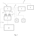
- the processing unit is configured to obtain the estimated output power by performing an output power estimation on the basis of data measured by condition monitoring sensors 5a and 5b, the data including vibration measurement data and magnetic flux density measurement data.
- the sensors may be part of the system 1 or external to the system 1.
- Database 6 and/or database 7 may optionally (not shown here) be stored in the memory unit 4.
- the processing unit 3 may be configured to perform at least some of, in particular all of, the calculations involved in obtaining the estimated output power.
- the processing unit may be connected via data connections 8 to one or more of the memory unit 4, sensors 5a and 5b, database 6 and database 7, and may be configured to obtain, via the data connections, any data required for performing the calculations.
- the processing unit may also provide functionality to serve as a control device configured to control the electric motor and/or other components of an industrial process in which the motor is used, particularly on the basis of the estimated output power.
- the processing unit may be configured to provide the estimated output power to a control device 10 external to the processing unit and configured to control the electric motor and/or other components, particularly on the basis of the estimated output power.
- the control device may be part of or external to the system 1.
- the system may comprise or be connected to a display device 9 configured to display a representation of the estimated output power.
- the processing unit may be connected to the display device via data connection 8 to provide the estimated output power to the display device.
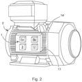
- Figure 2 illustrates a system 1 including the processing unit 3, sensors 5a and 5b, and a communication interface 12 for transmitting and receiving data.
- the system is included in a housing 13 and attached to a housing 14 of the electric motor 2.
- the electric motor 2 may be attached by means of a clamping device (not shown). It may also be attached to the electric motor in any other suitable manner.
- the method according to the invention is defined by the independent method claim.
- the method may comprise only some of the blocks and decisions outlined below and/or it may comprise additional steps. It may comprise modifications of the blocks and decisions outlined below. The order of the blocks and decisions outlined below may be different.
- the input, Data 1 consists of historical measurement data, e.g., from multiple measurements taken over a longer period.
- Block 1 entails finding the relation between operating points (consisting of speed and line frequency) and MFDRMS or other parameters derived from the magnetic flux density. Based on this relation, later steps may verify operating points for which the power can be reliably estimated.
- the principle behind finding the relation between the operating points and the MFDRMS is to fit a MFDRMS surface to the estimated operating points.
- the surface is fitted using three measured parameters which may all be measured by the condition monitoring sensors using magnetic flux density and vibration measurements.
- the three measured parameters are the rotor electrical frequency, rotational speed, and MFDRMS.
- any other parameter indicative of the strength of the magnetic flux density signal e.g., the amplitude of the dominant frequency, may be used.
- the rotor electrical frequency may be calculated from the line frequency and the speed of the motor
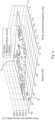
- Figure 4 illustrates an exemplary surface 11 fitted to historical measurement data, wherein outliers are indicated with circles 15.
- the MFDRMS depends on the operating point, i.e., the speed and rotor electrical frequency of the motor.
- the rotor electrical frequency is affected by the load of the motor. In other words, a certain operating point always has approximately the same MFDRMS value. Different operating points likely have different MFDRMS values.
- a low rotor electrical frequency and low speed the MFDRMS value is at its highest. It decreases with increasing rotor electrical frequency.
- the MFDRMS decreases with increasing speed.
- Block 2 and Decision 1 are optional, but they will improve the accuracy of the estimation if included in the method.
- Finding unreliable operating points (outliers) with the help of the surface provided by Block 1 is possible because the sensor can reliably measure the MFDRMS, but the speed and rotor electrical frequency measurements have a degree of uncertainty. This is especially valid for motors supplied by variable frequency drives (VFD). If the speed and rotor electrical frequency are wrong, the MFDRMS is still measured correctly. By comparing the calculated MFDRMS with the expected MFDRMS given by the surface based on the measured speed and rotor electrical frequency, we can determine if the MFDRMS fits the surface or not. If it does not fit, i.e., the difference between the measured MFDRMS and the expected MFDRMS is too great, the speed and/or the rotor electrical frequency were measured incorrectly, and the measurement can be classified as an outlier.
- VFD variable frequency drives
- Block 3 indicated by reference sign 104, describes method steps that optionally may be performed in preparation for the calculation of estimated output power on the basis of current measurement data, more specifically, steps in preparation for discarding unreliable data points. These steps are optional, but they will improve the accuracy of the estimation if included in the method.
- Block 3 includes the step of discarding any operating point measurement if it was classified as an outlier. Estimating the output power of this unreliably estimated operating point would yield an inaccurate result. The quality of the system is improved because the number of low accuracy output power estimates is decreased.
- Block 4 indicated by reference sign 105, and Decision 2, indicated by reference sign 106, describe the actual steps of estimating the power output on the basis of current measurement data, i.e., current measurement values, excluding any discarded measurement values (Data 5).
- the output power may be calculated based on the mathematical model of the motor, if available. It may not always be guaranteed that a mathematical model is available.
- the method may comprise the optional Decision 2, which checks if there is a mathematical model available. For example, models may be stored, e.g. based on the serial number of the motor, in a Model Database (Data 4). If the model is available, Data 5, i.e., current measurement values excluding discarded measurement values, is given to Block 4 and the output power is calculated based thereon.
- Data 4 Model Database
- Optional Block 5 indicated by reference sign 107, describes the steps taken in case the method comprises Decision 2 and Decision 2 determines that no mathematical model of the motor is available.
- the output power, as specified in Block 5 may then be estimated using a common equation which, for example, may be based on the operating point and the nameplate parameters of the motor. To do so, Block 5 may receive Data 5 and data from an Equation Database (Data 6), for example.
- Data 6 Equation Database
- Optional Block 6 indicated by reference sign 108, describes rendering a representation of estimated output power on a display device.
- the estimated output power may be used for further calculations, for controlling components of an industrial process or other uses already mentioned above.
- Reference sign 109 indicates the input data for Block 1, i.e., historical measurement data.
- Reference sign 110 indicates the input data for Block 2, i.e., recent measurement data.
- Reference sign 111 indicates the input data for Decision 1, i.e., a predetermined maximum allowed distance to surface.
- Reference sign 112 indicates the input data for Decision 2, e.g., a Model Database where available motor models are stored.
- Reference sign 113 indicates the input data for Block 4 and Block 5, i.e., remaining measurement values that remain after discarding measurement values in Block 3.
- Reference sign 114 indicates input data for Block 5, e.g. data from an equation database, for estimating power when no motor model is available.
Landscapes
- Engineering & Computer Science (AREA)
- Physics & Mathematics (AREA)
- General Physics & Mathematics (AREA)
- Power Engineering (AREA)
- Microelectronics & Electronic Packaging (AREA)
- Control Of Electric Motors In General (AREA)
Claims (15)
- System (1) zum Erhalten einer geschätzten Ausgangsleistung eines Elektromotors (2), wobei das System (1) eine Verarbeitungseinheit (3) umfasst, wobei die Verarbeitungseinheit (3) konfiguriert ist, die geschätzte Ausgangsleistung durch Durchführung einer Ausgangsleistungsschätzung auf Basis von durch Zustandsüberwachungssensoren (5a, 5b) gemessenen Daten zu erhalten, wobei die Daten Schwingungsmessdaten und Messdaten der magnetischen Flussdichte umfassen, dadurch gekennzeichnet, dass die Verarbeitungseinheit (3) ferner konfiguriert ist, Geschwindigkeitswerte und Netzfrequenzwerte aus den Schwingungsmessdaten und den Messdaten der magnetischen Flussdichte zu schätzen, um geschätzte Geschwindigkeitswerte und geschätzte Netzfrequenzwerte zu erhalten, zu bestimmen, ob einer der geschätzten Geschwindigkeitswerte und geschätzten Netzfrequenzwerte unzuverlässig ist, die als unzuverlässig bestimmten Geschwindigkeitswerte und Netzfrequenzwerte zu verwerfen und die Ausgangsleistungsschätzung auf Basis von zumindest einigen der geschätzten Geschwindigkeitswerte und zumindest einigen der geschätzten Netzfrequenzwerte durchzuführen, die nach dem Verwerfen der als unzuverlässig bestimmten Werte verbleiben.
- System (1) nach Anspruch 1, wobei die Verarbeitungseinheit (3) konfiguriert ist, die Ausgangsleistungsschätzung ausschließlich auf Basis der Schwingungsmessdaten und der Messdaten der magnetischen Flussdichte und/oder der aus den Schwingungsmessdaten und den Messdaten der magnetischen Flussdichte abgeleiteten Daten durchzuführen.
- System (1) nach Anspruch 2, wobei die Verarbeitungseinheit (3) konfiguriert ist, Daten, die mit aus historischen Messungen erhaltenen Geschwindigkeitswerten und Netzfrequenzwerten assoziiert sind, zu verwenden, um zu bestimmen, ob einer der geschätzten Geschwindigkeitswerte und geschätzten Netzfrequenzwerte unzuverlässig ist, insbesondere wobei die Verarbeitungseinheit konfiguriert ist, eine Beziehung zwischen aus historischen Messungen erhaltenen Geschwindigkeitswerten und Netzfrequenzwerten und einem Parameter, der die Stärke eines magnetischen Flussdichtesignals anzeigt, beispielsweise einem Effektivwert der magnetischen Flussdichte (MFDRMS) oder einer Amplitude der dominanten Frequenz, herzustellen und basierend auf dieser Beziehung zu bestimmen, ob einer der Werte unzuverlässig ist.
- System (1) nach Anspruch 2 oder 3, wobei das Bestimmen, ob einer der geschätzten Geschwindigkeitswerte und geschätzten Netzfrequenzwerte unzuverlässig ist, Folgendes umfasst:für ein Paar aus einem geschätzten Geschwindigkeitswert und einem geschätzten Netzfrequenzwert einen Wert eines/ des Parameters, der die Stärke eines/ des magnetischen Flussdichtesignals anzeigt, z. B. einen/ den Effektivwert der magnetischen Flussdichte, MFDRMS, oder eine/ die Amplitude der dominanten Frequenz, aus dem geschätzten Netzfrequenzwert zu berechnen und den berechneten Wert des Parameters, der die Stärke des magnetischen Flussdichtesignals anzeigt, mit einem erwarteten Wert des Parameters, der die Stärke des magnetischen Flussdichtesignals für einen Geschwindigkeitswert und einen Netzfrequenzwert anzeigt, die mit dem geschätzten Geschwindigkeitswert und dem geschätzten Netzfrequenzwert übereinstimmen, zu vergleichen,insbesondere die Differenz zwischen dem berechneten Wert des Parameters, der die Stärke des magnetischen Flussdichtesignals anzeigt, und dem erwarteten Wert des Parameters, der die Stärke des magnetischen Flussdichtesignals anzeigt, zu bestimmen und, falls festgestellt wird, dass die Differenz einen vorgegebenen Schwellenwert überschreitet, zu bestimmen, dass der geschätzte Geschwindigkeitswert und der geschätzte Netzfrequenzwert unzuverlässig sind.
- System (1) nach einem der Ansprüche 2 bis 4, wobei die Verarbeitungseinheit (3) konfiguriert ist, zu bestimmen, ob ein mathematisches Modell des Elektromotors verfügbar ist, das die Ausgangsleistung basierend auf Geschwindigkeitswerten und Netzfrequenzwerten modelliert, undwenn festgestellt wird, dass ein solches mathematisches Modell des Elektromotors verfügbar ist, die Ausgangsleistungsschätzung mittels des mathematischen Modells durchzuführen, indem zumindest einige der geschätzten Geschwindigkeitswerte und zumindest einige der geschätzten Netzfrequenzwerte in das mathematische Modell eingegeben werden, undwenn festgestellt wird, dass kein mathematisches Modell des Elektromotors, das die Ausgangsleistung basierend auf Geschwindigkeitswerten und Netzfrequenzwerten modelliert, verfügbar ist, die Ausgangsleistungsschätzung unter Verwendung einer Gleichung durchzuführen, welche eine Beziehung zwischen einer Netzfrequenz und der Ausgangsleistung des Elektromotors beschreibt.
- System (1) nach einem der Ansprüche 3 bis 5, wobei die Verarbeitungseinheit (3) konfiguriert ist, die Beziehung zwischen aus historischen Messungen erhaltenen Geschwindigkeitswerten und Netzfrequenzwerten und dem Parameter, der die Stärke eines magnetischen Flussdichtesignals anzeigt, durch Durchführung einer Vielzahl von Messungen zum Erhalten einer Vielzahl von Geschwindigkeitswerten und Netzfrequenzwerten, Bestimmen entsprechender magnetischer Flussdichtewerte und Durchführung eines Anpassungsschritts zum Erhalten des Parameters als Funktion von Geschwindigkeit und Netzfrequenz zu bestimmen,
insbesondere wobei die Verarbeitungseinheit konfiguriert ist, einen/den erwarteten Wert des Parameters, der die Stärke eines magnetischen Flussdichtesignals anzeigt, basierend auf der Beziehung zu bestimmen. - Computerimplementiertes Verfahren zum Erhalten einer geschätzten Ausgangsleistung eines Elektromotors (2), beispielsweise unter Verwendung des Systems (1) nach einem der vorhergehenden Ansprüche, wobei die geschätzte Ausgangsleistung durch Durchführung einer Ausgangsleistungsschätzung auf Basis von durch Zustandsüberwachungssensoren (5a, 5b) gemessenen Daten, wobei die Daten Schwingungsmessdaten und Messdaten der magnetischen Flussdichte umfassen, erhalten wird, und dadurch gekennzeichnet ist, dass das Verfahren ferner umfasst
Schätzen von Geschwindigkeitswerten und Netzfrequenzwerten aus den Schwingungsmessdaten und den Messdaten der magnetischen Flussdichte, um geschätzte Geschwindigkeitswerte und geschätzte Netzfrequenzwerte zu erhalten, Bestimmen, ob einer der geschätzten Geschwindigkeitswerte und geschätzten Netzfrequenzwerte unzuverlässig ist, Verwerfen der als unzuverlässig bestimmten Geschwindigkeitswerte und Netzfrequenzwerte, und Durchführen der Ausgangsleistungsschätzung auf Basis von zumindest einigen der geschätzten Geschwindigkeitswerte und zumindest einigen der geschätzten Netzfrequenzwerte, die nach dem Verwerfen der als unzuverlässig bestimmten Werte verbleiben. - Verfahren nach Anspruch 7, wobei das Verfahren ferner umfasst
die Ausgangsleistungsschätzung ausschließlich auf Basis der Schwingungsmessdaten und der Messdaten der magnetischen Flussdichte und/oder aus den Schwingungsmessdaten und den Messdaten der magnetischen Flussdichte abgeleiteten Daten durchzuführen. - Verfahren nach Anspruch 8, wobei das Verfahren ferner umfasst, Daten, die mit aus historischen Messungen erhaltenen Geschwindigkeitswerten und Netzfrequenzwerten assoziiert sind, zu verwenden, um zu bestimmen, ob einer der geschätzten Geschwindigkeitswerte und geschätzten Netzfrequenzwerte unzuverlässig ist,
insbesondere eine Beziehung zwischen aus historischen Messungen erhaltenen Geschwindigkeitswerten und Netzfrequenzwerten und einem Parameter, der die Stärke eines magnetischen Flussdichtesignals anzeigt, beispielsweise einem Effektivwert der magnetischen Flussdichte, MFDRMS, oder einer Amplitude der dominanten Frequenz, herzustellen und basierend auf dieser Beziehung zu bestimmen, ob einer der Geschwindigkeitswerte und Netzfrequenzwerte unzuverlässig ist. - Verfahren nach Anspruch 8 oder 9, wobei das Bestimmen, ob einer der geschätzten Geschwindigkeitswerte und geschätzten Netzfrequenzwerte unzuverlässig ist, Folgendes umfasst:
für ein Paar aus einem geschätzten Geschwindigkeitswert und einem geschätzten Netzfrequenzwert einen Wert eines/ des Parameters, der die Stärke eines/ des magnetischen Flussdichtesignals anzeigt, z. B. einen/ den Effektivwert der magnetischen Flussdichte, MFDRMS, oder eine/ die Amplitude der dominanten Frequenz, aus dem geschätzten Netzfrequenzwert zu berechnen und den berechneten Wert des Parameters, der die Stärke des magnetischen Flussdichtesignals anzeigt, mit einem erwarteten Wert des Parameters, der die Stärke des magnetischen Flussdichtesignals für einen Geschwindigkeitswert und einen Netzfrequenzwert anzeigt, die mit dem geschätzten Geschwindigkeitswert und dem geschätzten Netzfrequenzwert übereinstimmen, zu vergleichen, insbesondere die Differenz zwischen dem berechneten Wert des Parameters, der die Stärke des magnetischen Flussdichtesignals anzeigt, und dem erwarteten Wert des Parameters, der die Stärke des magnetischen Flussdichtesignals anzeigt, zu bestimmen und, falls festgestellt wird, dass die Differenz einen vorgegebenen Schwellenwert überschreitet, zu bestimmen, dass der geschätzte Geschwindigkeitswert und der geschätzte Netzfrequenzwert unzuverlässig sind. - Verfahren nach einem der Ansprüche 8 bis 10, wobei das Verfahren ferner umfasst, zu bestimmen, ob ein mathematisches Modell des Elektromotors, das die Ausgangsleistung basierend auf Geschwindigkeitswerten und Netzfrequenzwerten modelliert, verfügbar ist, und, falls bestimmt wird, dass das mathematische Modell verfügbar ist, die Ausgangsleistungsschätzung mittels des mathematischen Modells durchzuführen, indem zumindest einige der geschätzten Geschwindigkeitswerte und zumindest einige der geschätzten Netzfrequenzwerte in das mathematische Modell eingegeben werden, und, falls bestimmt wird, dass kein mathematisches Modell des Elektromotors, das die Ausgangsleistung basierend auf Geschwindigkeitswerten und Netzfrequenzwerten modelliert, verfügbar ist, die Ausgangsleistungsschätzung unter Verwendung einer Gleichung, die eine Beziehung zwischen einer Netzfrequenz und der Ausgangsleistung des Elektromotors beschreibt, durchzuführen.
- Verfahren nach einem der Ansprüche 9 bis 11, wobei das Bestimmen der Beziehung zwischen aus historischen Messungen erhaltenen Geschwindigkeitswerten und Netzfrequenzwerten und dem Parameter, der die Stärke eines magnetischen Flussdichtesignals anzeigt, Folgendes umfasst: Durchführung einer Vielzahl von Messungen zum Erhalten einer Vielzahl von Geschwindigkeitswerten und Netzfrequenzwerten, Bestimmen entsprechender magnetischer Flussdichtewerte und Durchführung eines Anpassungsschritts zum Erhalten des Parameters als Funktion von Geschwindigkeit und Netzfrequenz,
insbesondere umfasst das Verfahren das Bestimmen eines/ des erwarteten Wertes des Parameters, der die Stärke eines magnetischen Flussdichtesignals anzeigt, basierend auf der Beziehung. - Verfahren nach einem der Ansprüche 7 bis 12, wobei das Verfahren ferner umfasst, eine Darstellung der geschätzten Ausgangsleistung auf einem Anzeigegerät anzuzeigen und/oder die geschätzte Ausgangsleistung für eine nachfolgende Berechnung zu verwenden und/oder die geschätzte Ausgangsleistung zur Steuerung des Elektromotors und/oder zur Steuerung anderer Komponenten zu verwenden und/oder die geschätzte Ausgangsleistung in einem Speichergerät zu speichern und/oder einen Alarm auszulösen, wenn die geschätzte Ausgangsleistung einen ersten vorbestimmten Schwellenwert überschreitet und/oder unter einen zweiten vorbestimmten Schwellenwert fällt.
- Computerprogrammprodukt, das Anweisungen umfasst, die, wenn das Programm von einem Computer ausgeführt wird, den Computer veranlassen, das Verfahren nach einem der Ansprüche 7 bis 13 durchzuführen.
- Computerlesbares Medium, das Anweisungen umfasst, die, wenn sie von einem Computer ausgeführt werden, den Computer veranlassen, das Verfahren nach einem der Ansprüche 7 bis 13 durchzuführen.
Priority Applications (4)
| Application Number | Priority Date | Filing Date | Title |
|---|---|---|---|
| EP21196074.5A EP4148977B1 (de) | 2021-09-10 | 2021-09-10 | System und verfahren zur gewinnung einer geschätzten ausgangsleistung eines elektromotors |
| CN202280060722.9A CN117981209A (zh) | 2021-09-10 | 2022-09-08 | 用于获取电动机的估计的输出功率的系统和方法 |
| PCT/EP2022/074991 WO2023036872A1 (en) | 2021-09-10 | 2022-09-08 | System and method for obtaining an estimated output power of an electric motor |
| US18/599,440 US20240210474A1 (en) | 2021-09-10 | 2024-03-08 | System and Method for Obtaining an Estimated Output Power of an Electric Motor |
Applications Claiming Priority (1)
| Application Number | Priority Date | Filing Date | Title |
|---|---|---|---|
| EP21196074.5A EP4148977B1 (de) | 2021-09-10 | 2021-09-10 | System und verfahren zur gewinnung einer geschätzten ausgangsleistung eines elektromotors |
Publications (3)
| Publication Number | Publication Date |
|---|---|
| EP4148977A1 EP4148977A1 (de) | 2023-03-15 |
| EP4148977C0 EP4148977C0 (de) | 2025-07-02 |
| EP4148977B1 true EP4148977B1 (de) | 2025-07-02 |
Family
ID=77710690
Family Applications (1)
| Application Number | Title | Priority Date | Filing Date |
|---|---|---|---|
| EP21196074.5A Active EP4148977B1 (de) | 2021-09-10 | 2021-09-10 | System und verfahren zur gewinnung einer geschätzten ausgangsleistung eines elektromotors |
Country Status (4)
| Country | Link |
|---|---|
| US (1) | US20240210474A1 (de) |
| EP (1) | EP4148977B1 (de) |
| CN (1) | CN117981209A (de) |
| WO (1) | WO2023036872A1 (de) |
Citations (7)
| Publication number | Priority date | Publication date | Assignee | Title |
|---|---|---|---|---|
| US6199018B1 (en) | 1998-03-04 | 2001-03-06 | Emerson Electric Co. | Distributed diagnostic system |
| US20090119036A1 (en) | 2007-11-02 | 2009-05-07 | Emerson Climate Technologies, Inc. | Compressor sensor module |
| DE102009022107A1 (de) | 2009-05-20 | 2010-11-25 | Ksb Ag | Verfahren und Vorrichtung zur Betriebspunktbestimmung einer Arbeitsmaschine |
| DE102018114325A1 (de) | 2017-06-16 | 2018-12-20 | GM Global Technology Operations LLC | System und Verfahren zur Messung und Diagnose des Anfangsversatzes eines analogen Eingangssensors |
| CN110632512A (zh) | 2019-08-12 | 2019-12-31 | 西安交通大学 | 一种基于漏磁和振动信号的感应电机监测方法及装置 |
| US20200177117A1 (en) | 2018-11-30 | 2020-06-04 | The Trustees Of Columbia University In The City Of New York | Systems and methods for high performance filtering techniques for sensorless direct position and speed estimation |
| US20200333400A1 (en) | 2017-12-19 | 2020-10-22 | Abb Schweiz Ag | Condition monitoring device for monitoring operations of motor |
-
2021
- 2021-09-10 EP EP21196074.5A patent/EP4148977B1/de active Active
-
2022
- 2022-09-08 CN CN202280060722.9A patent/CN117981209A/zh active Pending
- 2022-09-08 WO PCT/EP2022/074991 patent/WO2023036872A1/en not_active Ceased
-
2024
- 2024-03-08 US US18/599,440 patent/US20240210474A1/en active Pending
Patent Citations (7)
| Publication number | Priority date | Publication date | Assignee | Title |
|---|---|---|---|---|
| US6199018B1 (en) | 1998-03-04 | 2001-03-06 | Emerson Electric Co. | Distributed diagnostic system |
| US20090119036A1 (en) | 2007-11-02 | 2009-05-07 | Emerson Climate Technologies, Inc. | Compressor sensor module |
| DE102009022107A1 (de) | 2009-05-20 | 2010-11-25 | Ksb Ag | Verfahren und Vorrichtung zur Betriebspunktbestimmung einer Arbeitsmaschine |
| DE102018114325A1 (de) | 2017-06-16 | 2018-12-20 | GM Global Technology Operations LLC | System und Verfahren zur Messung und Diagnose des Anfangsversatzes eines analogen Eingangssensors |
| US20200333400A1 (en) | 2017-12-19 | 2020-10-22 | Abb Schweiz Ag | Condition monitoring device for monitoring operations of motor |
| US20200177117A1 (en) | 2018-11-30 | 2020-06-04 | The Trustees Of Columbia University In The City Of New York | Systems and methods for high performance filtering techniques for sensorless direct position and speed estimation |
| CN110632512A (zh) | 2019-08-12 | 2019-12-31 | 西安交通大学 | 一种基于漏磁和振动信号的感应电机监测方法及装置 |
Also Published As
| Publication number | Publication date |
|---|---|
| EP4148977C0 (de) | 2025-07-02 |
| US20240210474A1 (en) | 2024-06-27 |
| WO2023036872A1 (en) | 2023-03-16 |
| CN117981209A (zh) | 2024-05-03 |
| EP4148977A1 (de) | 2023-03-15 |
Similar Documents
| Publication | Publication Date | Title |
|---|---|---|
| CN112041819B (zh) | 用于监测和识别电驱动系统中的传感器故障的方法 | |
| US8763464B2 (en) | Method and apparatus for determining an operating point of a work machine | |
| CN110890855A (zh) | 一种电动汽车永磁同步电机的参数辨识方法 | |
| EP2354556A9 (de) | Pumpenverfahren mit einer frequenzwandlerbetriebenen Pumpe | |
| US10352324B2 (en) | Determining the delivery rate of a pump | |
| CN108418490B (zh) | 一种永磁同步电机旋变相对角度在线校正方法 | |
| Ramakrishnan et al. | Real time estimation of parameters for controlling and monitoring permanent magnet synchronous motors | |
| CN111082725A (zh) | 磁旋转编码器角度补偿方法、补偿系统和电机 | |
| WO2018090783A1 (zh) | 电机定子电阻的在线辨识方法、装置和电机控制系统 | |
| US20110140646A1 (en) | Methods and systems for induction machine control | |
| EP4148977B1 (de) | System und verfahren zur gewinnung einer geschätzten ausgangsleistung eines elektromotors | |
| WO2008065836A1 (fr) | Contrôleur de moteur et procédé permettant d'ajuster un filtre de sortie et dispositif permettant d'ajuster un filtre de sortie | |
| CN110557076B (zh) | 用于电动鼓风机电机的电机控制器 | |
| US11283380B2 (en) | Method and device for determining the rotational speed and the angle of rotation of a motor shaft of a mechanically commutated DC motor | |
| CN113640667A (zh) | 一种电机eol下线零点自动校准方法及系统 | |
| JPH0670567A (ja) | 電動機の制御ゲイン自動設定方法及びバックラッシュ検出方法 | |
| CN111742438A (zh) | 传感器装置和用于其运行的方法 | |
| CN105531920A (zh) | 车辆系统及用于该车辆系统的方法 | |
| US20240258953A1 (en) | Method for estimating the magnet temperature in an electrical machine, method for controlling said electrical machine, electronic device for estimating the magnet temperature in an electrical machine and system for controlling said electrical machine | |
| CN119766003B (zh) | 一种电流强度振荡扩大无刷电机零位动态标定方法及装置 | |
| US20250296445A1 (en) | Method and Device for Monitoring an Electric Drive of a Motor Vehicle | |
| CN120454540B (zh) | 一种基于高频信号注入的无刷电机起动控制方法及系统 | |
| EP4167469B1 (de) | Verfahren und vorrichtung zur aktualisierung von kalibrierungsdaten eines motors, elektronische vorrichtung und speichermedium | |
| CN121635091A (zh) | 一种基于数控机床的外置机械骨骼生产监控系统 | |
| CN121907070A (zh) | 永磁同步风力发电机参数在线辨识方法、装置、设备及存储介质 |
Legal Events
| Date | Code | Title | Description |
|---|---|---|---|
| PUAI | Public reference made under article 153(3) epc to a published international application that has entered the european phase |
Free format text: ORIGINAL CODE: 0009012 |
|
| STAA | Information on the status of an ep patent application or granted ep patent |
Free format text: STATUS: THE APPLICATION HAS BEEN PUBLISHED |
|
| AK | Designated contracting states |
Kind code of ref document: A1 Designated state(s): AL AT BE BG CH CY CZ DE DK EE ES FI FR GB GR HR HU IE IS IT LI LT LU LV MC MK MT NL NO PL PT RO RS SE SI SK SM TR |
|
| STAA | Information on the status of an ep patent application or granted ep patent |
Free format text: STATUS: REQUEST FOR EXAMINATION WAS MADE |
|
| 17P | Request for examination filed |
Effective date: 20230825 |
|
| RBV | Designated contracting states (corrected) |
Designated state(s): AL AT BE BG CH CY CZ DE DK EE ES FI FR GB GR HR HU IE IS IT LI LT LU LV MC MK MT NL NO PL PT RO RS SE SI SK SM TR |
|
| GRAP | Despatch of communication of intention to grant a patent |
Free format text: ORIGINAL CODE: EPIDOSNIGR1 |
|
| STAA | Information on the status of an ep patent application or granted ep patent |
Free format text: STATUS: GRANT OF PATENT IS INTENDED |
|
| INTG | Intention to grant announced |
Effective date: 20250224 |
|
| GRAS | Grant fee paid |
Free format text: ORIGINAL CODE: EPIDOSNIGR3 |
|
| GRAA | (expected) grant |
Free format text: ORIGINAL CODE: 0009210 |
|
| STAA | Information on the status of an ep patent application or granted ep patent |
Free format text: STATUS: THE PATENT HAS BEEN GRANTED |
|
| AK | Designated contracting states |
Kind code of ref document: B1 Designated state(s): AL AT BE BG CH CY CZ DE DK EE ES FI FR GB GR HR HU IE IS IT LI LT LU LV MC MK MT NL NO PL PT RO RS SE SI SK SM TR |
|
| REG | Reference to a national code |
Ref country code: GB Ref legal event code: FG4D |
|
| REG | Reference to a national code |
Ref country code: CH Ref legal event code: EP |
|
| REG | Reference to a national code |
Ref country code: DE Ref legal event code: R096 Ref document number: 602021033231 Country of ref document: DE |
|
| REG | Reference to a national code |
Ref country code: IE Ref legal event code: FG4D |
|
| U01 | Request for unitary effect filed |
Effective date: 20250731 |
|
| U07 | Unitary effect registered |
Designated state(s): AT BE BG DE DK EE FI FR IT LT LU LV MT NL PT RO SE SI Effective date: 20250811 |
|
| U20 | Renewal fee for the european patent with unitary effect paid |
Year of fee payment: 5 Effective date: 20250924 |
|
| PG25 | Lapsed in a contracting state [announced via postgrant information from national office to epo] |
Ref country code: IS Free format text: LAPSE BECAUSE OF FAILURE TO SUBMIT A TRANSLATION OF THE DESCRIPTION OR TO PAY THE FEE WITHIN THE PRESCRIBED TIME-LIMIT Effective date: 20251102 |
|
| PG25 | Lapsed in a contracting state [announced via postgrant information from national office to epo] |
Ref country code: NO Free format text: LAPSE BECAUSE OF FAILURE TO SUBMIT A TRANSLATION OF THE DESCRIPTION OR TO PAY THE FEE WITHIN THE PRESCRIBED TIME-LIMIT Effective date: 20251002 |
|
| PG25 | Lapsed in a contracting state [announced via postgrant information from national office to epo] |
Ref country code: HR Free format text: LAPSE BECAUSE OF FAILURE TO SUBMIT A TRANSLATION OF THE DESCRIPTION OR TO PAY THE FEE WITHIN THE PRESCRIBED TIME-LIMIT Effective date: 20250702 |
|
| PG25 | Lapsed in a contracting state [announced via postgrant information from national office to epo] |
Ref country code: GR Free format text: LAPSE BECAUSE OF FAILURE TO SUBMIT A TRANSLATION OF THE DESCRIPTION OR TO PAY THE FEE WITHIN THE PRESCRIBED TIME-LIMIT Effective date: 20251003 |
|
| PG25 | Lapsed in a contracting state [announced via postgrant information from national office to epo] |
Ref country code: CZ Free format text: LAPSE BECAUSE OF FAILURE TO SUBMIT A TRANSLATION OF THE DESCRIPTION OR TO PAY THE FEE WITHIN THE PRESCRIBED TIME-LIMIT Effective date: 20250702 |
|
| PG25 | Lapsed in a contracting state [announced via postgrant information from national office to epo] |
Ref country code: PL Free format text: LAPSE BECAUSE OF FAILURE TO SUBMIT A TRANSLATION OF THE DESCRIPTION OR TO PAY THE FEE WITHIN THE PRESCRIBED TIME-LIMIT Effective date: 20250702 |
|
| PG25 | Lapsed in a contracting state [announced via postgrant information from national office to epo] |
Ref country code: RS Free format text: LAPSE BECAUSE OF FAILURE TO SUBMIT A TRANSLATION OF THE DESCRIPTION OR TO PAY THE FEE WITHIN THE PRESCRIBED TIME-LIMIT Effective date: 20251002 |
|
| PG25 | Lapsed in a contracting state [announced via postgrant information from national office to epo] |
Ref country code: ES Free format text: LAPSE BECAUSE OF FAILURE TO SUBMIT A TRANSLATION OF THE DESCRIPTION OR TO PAY THE FEE WITHIN THE PRESCRIBED TIME-LIMIT Effective date: 20250702 |
|
| PLBI | Opposition filed |
Free format text: ORIGINAL CODE: 0009260 |
|
| PG25 | Lapsed in a contracting state [announced via postgrant information from national office to epo] |
Ref country code: SM Free format text: LAPSE BECAUSE OF FAILURE TO SUBMIT A TRANSLATION OF THE DESCRIPTION OR TO PAY THE FEE WITHIN THE PRESCRIBED TIME-LIMIT Effective date: 20250702 |
|
| REG | Reference to a national code |
Ref country code: CH Ref legal event code: L11 Free format text: ST27 STATUS EVENT CODE: U-0-0-L10-L11 (AS PROVIDED BY THE NATIONAL OFFICE) Effective date: 20260409 |
|
| PLAB | Opposition data, opponent's data or that of the opponent's representative modified |
Free format text: ORIGINAL CODE: 0009299OPPO |
|
| REG | Reference to a national code |
Ref country code: CH Ref legal event code: L10 Free format text: ST27 STATUS EVENT CODE: U-0-0-L10-L00 (AS PROVIDED BY THE NATIONAL OFFICE) Effective date: 20260416 |
|
| PLAX | Notice of opposition and request to file observation + time limit sent |
Free format text: ORIGINAL CODE: EPIDOSNOBS2 |
|
| PG25 | Lapsed in a contracting state [announced via postgrant information from national office to epo] |
Ref country code: SK Free format text: LAPSE BECAUSE OF FAILURE TO SUBMIT A TRANSLATION OF THE DESCRIPTION OR TO PAY THE FEE WITHIN THE PRESCRIBED TIME-LIMIT Effective date: 20250702 |