EP4148923A1 - Dual tongue strap cleat bracket - Google Patents
Dual tongue strap cleat bracket Download PDFInfo
- Publication number
- EP4148923A1 EP4148923A1 EP22191905.3A EP22191905A EP4148923A1 EP 4148923 A1 EP4148923 A1 EP 4148923A1 EP 22191905 A EP22191905 A EP 22191905A EP 4148923 A1 EP4148923 A1 EP 4148923A1
- Authority
- EP
- European Patent Office
- Prior art keywords
- tongue
- bracket
- support member
- extends
- slot
- Prior art date
- Legal status (The legal status is an assumption and is not a legal conclusion. Google has not performed a legal analysis and makes no representation as to the accuracy of the status listed.)
- Pending
Links
Images







Classifications
-
- H—ELECTRICITY
- H02—GENERATION; CONVERSION OR DISTRIBUTION OF ELECTRIC POWER
- H02G—INSTALLATION OF ELECTRIC CABLES OR LINES, OR OF COMBINED OPTICAL AND ELECTRIC CABLES OR LINES
- H02G3/00—Installations of electric cables or lines or protective tubing therefor in or on buildings, equivalent structures or vehicles
- H02G3/30—Installations of cables or lines on walls, floors or ceilings
- H02G3/32—Installations of cables or lines on walls, floors or ceilings using mounting clamps
-
- F—MECHANICAL ENGINEERING; LIGHTING; HEATING; WEAPONS; BLASTING
- F16—ENGINEERING ELEMENTS AND UNITS; GENERAL MEASURES FOR PRODUCING AND MAINTAINING EFFECTIVE FUNCTIONING OF MACHINES OR INSTALLATIONS; THERMAL INSULATION IN GENERAL
- F16L—PIPES; JOINTS OR FITTINGS FOR PIPES; SUPPORTS FOR PIPES, CABLES OR PROTECTIVE TUBING; MEANS FOR THERMAL INSULATION IN GENERAL
- F16L3/00—Supports for pipes, cables or protective tubing, e.g. hangers, holders, clamps, cleats, clips, brackets
- F16L3/22—Supports for pipes, cables or protective tubing, e.g. hangers, holders, clamps, cleats, clips, brackets specially adapted for supporting a number of parallel pipes at intervals
- F16L3/23—Supports for pipes, cables or protective tubing, e.g. hangers, holders, clamps, cleats, clips, brackets specially adapted for supporting a number of parallel pipes at intervals for a bundle of pipes or a plurality of pipes placed side by side in contact with each other
- F16L3/233—Supports for pipes, cables or protective tubing, e.g. hangers, holders, clamps, cleats, clips, brackets specially adapted for supporting a number of parallel pipes at intervals for a bundle of pipes or a plurality of pipes placed side by side in contact with each other by means of a flexible band
-
- H—ELECTRICITY
- H02—GENERATION; CONVERSION OR DISTRIBUTION OF ELECTRIC POWER
- H02G—INSTALLATION OF ELECTRIC CABLES OR LINES, OR OF COMBINED OPTICAL AND ELECTRIC CABLES OR LINES
- H02G3/00—Installations of electric cables or lines or protective tubing therefor in or on buildings, equivalent structures or vehicles
- H02G3/02—Details
- H02G3/04—Protective tubing or conduits, e.g. cable ladders or cable troughs
- H02G3/0456—Ladders or other supports
-
- H—ELECTRICITY
- H02—GENERATION; CONVERSION OR DISTRIBUTION OF ELECTRIC POWER
- H02G—INSTALLATION OF ELECTRIC CABLES OR LINES, OR OF COMBINED OPTICAL AND ELECTRIC CABLES OR LINES
- H02G3/00—Installations of electric cables or lines or protective tubing therefor in or on buildings, equivalent structures or vehicles
- H02G3/30—Installations of cables or lines on walls, floors or ceilings
-
- F—MECHANICAL ENGINEERING; LIGHTING; HEATING; WEAPONS; BLASTING
- F16—ENGINEERING ELEMENTS AND UNITS; GENERAL MEASURES FOR PRODUCING AND MAINTAINING EFFECTIVE FUNCTIONING OF MACHINES OR INSTALLATIONS; THERMAL INSULATION IN GENERAL
- F16L—PIPES; JOINTS OR FITTINGS FOR PIPES; SUPPORTS FOR PIPES, CABLES OR PROTECTIVE TUBING; MEANS FOR THERMAL INSULATION IN GENERAL
- F16L3/00—Supports for pipes, cables or protective tubing, e.g. hangers, holders, clamps, cleats, clips, brackets
- F16L3/24—Supports for pipes, cables or protective tubing, e.g. hangers, holders, clamps, cleats, clips, brackets with special member for attachment to profiled girders
- F16L3/243—Supports for pipes, cables or protective tubing, e.g. hangers, holders, clamps, cleats, clips, brackets with special member for attachment to profiled girders the special member being inserted in the profiled girder
- F16L3/2431—Supports for pipes, cables or protective tubing, e.g. hangers, holders, clamps, cleats, clips, brackets with special member for attachment to profiled girders the special member being inserted in the profiled girder the special member being inserted and subsequently rotated to a limited extent
-
- H—ELECTRICITY
- H02—GENERATION; CONVERSION OR DISTRIBUTION OF ELECTRIC POWER
- H02G—INSTALLATION OF ELECTRIC CABLES OR LINES, OR OF COMBINED OPTICAL AND ELECTRIC CABLES OR LINES
- H02G3/00—Installations of electric cables or lines or protective tubing therefor in or on buildings, equivalent structures or vehicles
- H02G3/02—Details
- H02G3/06—Joints for connecting lengths of protective tubing or channels, to each other or to casings, e.g. to distribution boxes; Ensuring electrical continuity in the joint
- H02G3/0608—Joints for connecting non cylindrical conduits, e.g. channels
Definitions
- the present invention relates to a bracket, and more particularly to a dual tongue strap cleat bracket for a locking strap cleat, bracket strap cleat, or other strap cleats, used to secure cables to strut rungs of a ladder rack.
- Conventional cable cleats have been typically used to secure wire or cable bundles to panels, ladder racks, or similar structural support members.
- the cable cleats include a mounting surface and a body portion that receives the wires or a cable bundle.
- Conventional cable cleats are generally difficult and time consuming to install. Thus, it is desirable to provide a bracket that is efficiently installed thereby significantly reducing labor costs and increasing productivity.
- the present invention is directed to a bracket that is designed to receive a locking strap cleat, a buckle strap cleat, or a strap cleat having other locking mechanisms, and that is designed to be secured to a support member.
- the bracket includes a first tongue, a second tongue parallel to the first tongue, and a riser section connecting the first tongue and the second tongue.
- the first and second tongues each include a slot for receiving a fastener.
- the first tongue is adapted to receive one of the cables and the locking strap cleat or the support member and the second tongue is adapted to receive one of the cables and the locking strap cleat or the support member.
- FIG. 1 illustrates the dual tongue strap cleat bracket 20, or dual tongue bracket, of the present invention and a locking strap cleat 100 securing a trefoil cable configuration to a support member 120, such as a strut rung of a ladder rack.
- the locking strap cleat is a stainless-steel strap secured by a ball-locking head for high retained tension (locking head not illustrated).
- the stainless-steel strap cleat may also be secured by a buckle (buckle strap cleat) or another locking mechanism.
- the strut rung 120 has a top member 122, two side walls 124, lower flanges 126 extending towards the center of the strut rung 120, inner flanges 128 extending from the lower flanges 126 towards the top member 122 of the strut rung 120, and an opening 130.
- the strut rung 120 may also include a plurality of openings 132 extending along the top member 122 (see FIG. 12 ).
- a cushion sleeve 110 is positioned, if desired, between the locking strap cleat 100 and cables 150 for added protection and to prevent damage to the cables 150.
- the dual tongue bracket 20 is secured to the strut rung 120 by a standard strut nut 40 and bolt 46.
- the strut nut 40 includes two indentations 42 and a center threaded hole 44.
- the dual tongue strap cleat bracket 20 may also be secured to the strut rung 120 by a standard nut 50 and bolt 52.
- FIGS. 2 and 3 illustrate the dual tongue strap cleat bracket 20 with a strut nut 40 and fastener 46.
- the dual tongue strap cleat bracket 20 includes two tongues 22A, 22B that are connected by a riser section 30.
- the tongues 22A, 22B are parallel to each other.
- Each tongue 22A, 22B extends in a direction opposite of the other tongue.
- Each tongue 22A, 22B is designed so that it can be connected to a support member 120 or a locking strap cleat 100.
- Each tongue 22A, 22B includes a slot 24A, 24B positioned at the center of the tongue 22A, 22B, respectively.
- the slot size in each tongue varies to accommodate fasteners of varying sizes.
- the slots 24A, 24B are designed to be used with either SAE or metric fasteners or hardware.
- the first slot 24A is 0.375 inch (10 mm) and the second slot 24B is 0.3125 inch (8 mm).
- the slot size and shape can be modified to accommodate customer requirements.
- the dual tongue bracket 20 with varying slot sizes can accommodate different support member or strut rung widths providing installation flexibility. Additionally, the riser section 30 height can be modified to accommodate support members of various strut rung heights.
- the dual tongue bracket 20 also includes retaining flanges 28A, 28B extending at an angle from the distal ends 26A, 26B of each tongue. As illustrated in FIGS. 2-3 , one retaining flange 28B extends downwards from the upper tongue 22B and one retaining flange 28A extends upwards from the lower tongue 22A.
- the retaining flanges 28A, 28B are designed to keep the locking strap cleat 100 from sliding off of the dual tongue bracket 20.
- FIGS. 4-11 illustrate the dual tongue strap cleat bracket 20 being installed onto the strut rung 120.
- the dual tongue bracket 20 is positioned with the tongue 22B having the desired slot size 28B located over the strut rung 120.
- the dual tongue bracket could be positioned with the slot 28A located over the strut rung 120.
- a fastener 46 such as a bolt, is positioned through the slot 28B of the dual tongue bracket 20 into a strut nut 40 and the strut nut 40 is rotated so that the strut nut 40 can be positioned in the strut rung 120.
- the bolt 46 and strut nut 40 are rotated ( FIG. 6 ) so the indentations 42 in the strut nut 40 are positioned to receive the inner flanges 128 of the strut rung 120 (see FIGS. 6 and 10 ). As illustrated in FIGS. 7 and 11 , the bolt 46 is tightened causing the strut nut 40 to engage the strut rung 120 and secure the dual tongue bracket 20 to the strut rung 120.
- a locking strap cleat 100 is used to secure cables to the dual tongue bracket 20.
- a cushion sleeve 110 and a locking strap cleat 100 can be wrapped around the free or open tongue 22A to secure a trefoil cable configuration.
- a trefoil cable configuration is illustrated, the dual tongue bracket 20 and locking strap cleat 100 can secure various cable arrangements including single, double, trefoil, and quad cable arrangements.
- FIGS. 12-14 illustrate an alternative configuration with the dual tongue bracket 20 secured to the strut rung 120 by a standard nut 50 and bolt 52. This configuration is desirable if the end user does not want the bracket 20 to slide when a lateral force is applied.
- the standard nut 50 and bolt 52 secures the dual tongue bracket 20 to the strut rung 120 to prohibit lateral movement.
- the dual tongue strap cleat bracket of the present invention provides many advantages over standard cleat brackets.
- the dual tongue strap cleat bracket is a low-cost, single piece bracket.
- the bracket is designed with two slot sizes per bracket which accommodates multiple support member widths.
- the slots are also designed to accept multiple fastener sizes.
- the riser section of the bracket may be modified to accommodate various support member heights.
Landscapes
- Engineering & Computer Science (AREA)
- Architecture (AREA)
- Civil Engineering (AREA)
- Structural Engineering (AREA)
- General Engineering & Computer Science (AREA)
- Mechanical Engineering (AREA)
- Supports For Pipes And Cables (AREA)
Abstract
Description
- The present invention relates to a bracket, and more particularly to a dual tongue strap cleat bracket for a locking strap cleat, bracket strap cleat, or other strap cleats, used to secure cables to strut rungs of a ladder rack.
- Conventional cable cleats have been typically used to secure wire or cable bundles to panels, ladder racks, or similar structural support members. The cable cleats include a mounting surface and a body portion that receives the wires or a cable bundle. Conventional cable cleats, however, are generally difficult and time consuming to install. Thus, it is desirable to provide a bracket that is efficiently installed thereby significantly reducing labor costs and increasing productivity.
- The present invention is directed to a bracket that is designed to receive a locking strap cleat, a buckle strap cleat, or a strap cleat having other locking mechanisms, and that is designed to be secured to a support member. The bracket includes a first tongue, a second tongue parallel to the first tongue, and a riser section connecting the first tongue and the second tongue. The first and second tongues each include a slot for receiving a fastener. The first tongue is adapted to receive one of the cables and the locking strap cleat or the support member and the second tongue is adapted to receive one of the cables and the locking strap cleat or the support member.
-
-
FIG. 1 is a perspective view of the dual tongue strap cleat bracket of the present invention and a locking strap cleat securing a trefoil cable configuration to a support member. -
FIG. 2 is a perspective view of the dual tongue bracket ofFIG. 1 with a strut nut and fastener. -
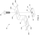
FIG. 3 is an exploded view of the dual tongue bracket, strut nut, and fastener ofFIG. 2 . -
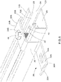
FIG. 4 is a perspective view of the dual tongue bracket, strut nut, and fastener ofFIG. 2 positioned to be inserted in the support member. -
FIG. 5 is a perspective view of the dual tongue bracket, strut nut, and fastener ofFIG. 2 partially installed on the support member. -
FIG. 6 is a perspective view of the dual tongue bracket, strut nut, and fastener ofFIG. 2 partially installed on the support member with the strut nut rotated. -
FIG. 7 is a perspective view of the dual tongue bracket, strut nut, and fastener ofFIG. 2 installed on the support member. -
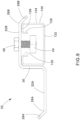
FIG. 8 is a side view of the dual tongue bracket, strut nut, and fastener ofFIG. 3 . -
FIG. 9 is a side view of the dual tongue bracket, strut nut, and fastener ofFIG. 5 partially installed on the support member. -
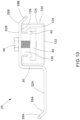
FIG. 10 is a side view of the dual tongue bracket, strut nut, and fastener ofFIG. 6 partially installed on the support member with the strut nut rotated. -
FIG. 11 is a side view of the dual tongue bracket, strut nut, and fastener ofFIG. 7 installed on the support member. -
FIG. 12 is a perspective view of the dual tongue strap cleat bracket of the present invention and a locking strap cleat securing a trefoil cable configuration to a support member. -
FIG. 13 is a cross sectional view of the dual tongue strap cleat bracket secured to a support member taken along line 13-13 ofFIG. 12 . -
FIG. 14 is an exploded view of the dual tongue strap cleat bracket and support member ofFIG. 12 . -
FIG. 1 illustrates the dual tonguestrap cleat bracket 20, or dual tongue bracket, of the present invention and a lockingstrap cleat 100 securing a trefoil cable configuration to asupport member 120, such as a strut rung of a ladder rack. The locking strap cleat is a stainless-steel strap secured by a ball-locking head for high retained tension (locking head not illustrated). The stainless-steel strap cleat may also be secured by a buckle (buckle strap cleat) or another locking mechanism. Thestrut rung 120 has atop member 122, twoside walls 124,lower flanges 126 extending towards the center of thestrut rung 120,inner flanges 128 extending from thelower flanges 126 towards thetop member 122 of thestrut rung 120, and anopening 130. Thestrut rung 120 may also include a plurality ofopenings 132 extending along the top member 122 (seeFIG. 12 ). Acushion sleeve 110 is positioned, if desired, between thelocking strap cleat 100 andcables 150 for added protection and to prevent damage to thecables 150. - The
dual tongue bracket 20 is secured to thestrut rung 120 by astandard strut nut 40 andbolt 46. Thestrut nut 40 includes twoindentations 42 and a center threadedhole 44. However, as illustrated and discussed with respect toFIGS. 12-14 , the dual tonguestrap cleat bracket 20 may also be secured to thestrut rung 120 by astandard nut 50 andbolt 52. -
FIGS. 2 and3 illustrate the dual tonguestrap cleat bracket 20 with astrut nut 40 and fastener 46. The dual tonguestrap cleat bracket 20 includes twotongues riser section 30. Thetongues tongue tongue support member 120 or alocking strap cleat 100. - Each
tongue slot tongue slots dual tongue bracket 20, thefirst slot 24A is 0.375 inch (10 mm) and thesecond slot 24B is 0.3125 inch (8 mm). The slot size and shape can be modified to accommodate customer requirements. - The
dual tongue bracket 20 with varying slot sizes can accommodate different support member or strut rung widths providing installation flexibility. Additionally, theriser section 30 height can be modified to accommodate support members of various strut rung heights. - The
dual tongue bracket 20 also includes retainingflanges distal ends FIGS. 2-3 , oneretaining flange 28B extends downwards from theupper tongue 22B and oneretaining flange 28A extends upwards from thelower tongue 22A. Theretaining flanges locking strap cleat 100 from sliding off of thedual tongue bracket 20. -
FIGS. 4-11 illustrate the dual tonguestrap cleat bracket 20 being installed onto thestrut rung 120. In the illustrated example, thedual tongue bracket 20 is positioned with thetongue 22B having the desiredslot size 28B located over thestrut rung 120. However, the dual tongue bracket could be positioned with theslot 28A located over thestrut rung 120. Afastener 46, such as a bolt, is positioned through theslot 28B of thedual tongue bracket 20 into astrut nut 40 and thestrut nut 40 is rotated so that thestrut nut 40 can be positioned in thestrut rung 120. Once thestrut nut 40 is installed in the strut rung 120 (FIG. 5 ), thebolt 46 andstrut nut 40 are rotated (FIG. 6 ) so theindentations 42 in thestrut nut 40 are positioned to receive theinner flanges 128 of the strut rung 120 (seeFIGS. 6 and10 ). As illustrated inFIGS. 7 and11 , thebolt 46 is tightened causing thestrut nut 40 to engage thestrut rung 120 and secure thedual tongue bracket 20 to thestrut rung 120. - Once the
dual tongue bracket 20 has been secured to thestrut rung 120, alocking strap cleat 100 is used to secure cables to thedual tongue bracket 20. As illustrated inFIG. 1 , acushion sleeve 110 and alocking strap cleat 100 can be wrapped around the free oropen tongue 22A to secure a trefoil cable configuration. Although a trefoil cable configuration is illustrated, thedual tongue bracket 20 andlocking strap cleat 100 can secure various cable arrangements including single, double, trefoil, and quad cable arrangements. -
FIGS. 12-14 illustrate an alternative configuration with thedual tongue bracket 20 secured to thestrut rung 120 by astandard nut 50 andbolt 52. This configuration is desirable if the end user does not want thebracket 20 to slide when a lateral force is applied. Thestandard nut 50 andbolt 52 secures thedual tongue bracket 20 to thestrut rung 120 to prohibit lateral movement. - The dual tongue strap cleat bracket of the present invention provides many advantages over standard cleat brackets. The dual tongue strap cleat bracket is a low-cost, single piece bracket. The bracket is designed with two slot sizes per bracket which accommodates multiple support member widths. The slots are also designed to accept multiple fastener sizes. Additionally, the riser section of the bracket may be modified to accommodate various support member heights.
- Furthermore, while the particular preferred embodiments of the present invention have been shown and described, it will be obvious to those skilled in the art that changes and modifications may be made without departing from the teaching of the invention. The matter set forth in the foregoing description and accompanying drawings is offered by way of illustration only and not as limitation. The actual scope of the invention is intended to be defined in the following claims when viewed in their proper perspective based on the prior art.
Claims (15)
- A bracket for receiving a locking strap cleat to secure cables to a support member, the bracket comprising:a first tongue with a slot, the first tongue is adapted to receive one of cables and a support member;a second tongue parallel to the first tongue, the second tongue having a slot, the second tongue is adapted to receive one of cables and a support member; anda riser section connecting the first tongue and the second tongue.
- The bracket of claim 1, wherein the first tongue extends from the riser section in a first direction and the second tongue extends from the riser section in a second direction opposite of the first direction.
- The bracket of claim 1 or 2, wherein a retaining flange extends at an angle from a distal end of the first tongue and a retaining flange extends at an angle from a distal end of the second tongue.
- The bracket of claim 3, wherein the retaining flange extending from the distal of the first tongue extends upwardly away from the first tongue and the retaining flange extending from the distal end of the second tongue extends downwardly away from the second tongue.
- An assembly for securing cables to a support member, the assembly comprising:a bracket adapted to be secured to a support member, wherein the bracket having a first tongue with a slot, a second tongue with a slot, and a riser section connecting the first tongue and the second tongue, and wherein the second tongue is parallel to the first tongue;a locking strap cleat wrapped around one of the first tongue and the second tongue of the bracket for securing the cables to the bracket and the support member.
- The assembly of claim 1 or 5, wherein the slot in the first tongue is larger than the slot in the second tongue.
- The assembly of claim 5 or 6, wherein the first tongue extends from the riser section in a first direction and the second tongue extends from the riser section in a second direction opposite of the first direction.
- The assembly of any of claims 5 to 7, wherein a retaining flange extends at an angle from a distal end of the first tongue and a retaining flange extends at an angle from a distal end of the second tongue.
- The assembly of claim 8, wherein the retaining flange extending from the distal of the first tongue extends upwardly away from the first tongue and the retaining flange extending from the distal end of the second tongue extends downwardly away from the second tongue.
- A cable bundling assembly comprising:a support member;at least one cable;a bracket having a first tongue receiving the at least one cable, a second tongue secured to the support member, and a riser section connecting the first tongue and the second tongue; anda locking strap cleat wrapped around the first tongue of the bracket for securing the at least one cable to the bracket.
- The cable bundling assembly of claim 10, wherein the support member has a top member, side walls, lower flanges, and inner flanges; and wherein a fastener and a nut secure the second tongue of the bracket to the support member.
- The cable bundling assembly of claim 10 or 11, wherein the first tongue of the bracket has a slot and the second tongue of the bracket has a slot; wherein the slot in the first tongue is larger than the slot in the second tongue.
- The cable bundling assembly of any of claims 10 to 12, wherein the first tongue extends from the riser section in a first direction and the second tongue extends from the riser section in a second direction opposite of the first direction.
- The cable bundling assembly of any of claims 10 to 13, wherein a retaining flange extends at an angle from a distal end of the first tongue and a retaining flange extends at an angle from a distal end of the second tongue.
- The cable bundling assembly of claim 14, wherein the retaining flange extending from the distal of the first tongue extends upwardly away from the first tongue and the retaining flange extending from the distal end of the second tongue extends downwardly away from the second tongue.
Applications Claiming Priority (1)
| Application Number | Priority Date | Filing Date | Title |
|---|---|---|---|
| US17/447,309 US11677227B2 (en) | 2021-09-10 | 2021-09-10 | Dual tongue strap cleat bracket |
Publications (1)
| Publication Number | Publication Date |
|---|---|
| EP4148923A1 true EP4148923A1 (en) | 2023-03-15 |
Family
ID=83059355
Family Applications (1)
| Application Number | Title | Priority Date | Filing Date |
|---|---|---|---|
| EP22191905.3A Pending EP4148923A1 (en) | 2021-09-10 | 2022-08-24 | Dual tongue strap cleat bracket |
Country Status (2)
| Country | Link |
|---|---|
| US (1) | US11677227B2 (en) |
| EP (1) | EP4148923A1 (en) |
Families Citing this family (4)
| Publication number | Priority date | Publication date | Assignee | Title |
|---|---|---|---|---|
| GB2615902B (en) * | 2019-05-11 | 2024-01-03 | Gripple Ltd | Connecting device |
| EP4485722A1 (en) * | 2023-06-29 | 2025-01-01 | Ab Wibe | Modular cable rack and support system |
| US20250102080A1 (en) * | 2023-09-22 | 2025-03-27 | PTW Products Inc. | Conduit support assembly |
| GB2635323B (en) * | 2023-10-31 | 2026-03-11 | Hellermanntyton Ltd | Cable management device |
Citations (3)
| Publication number | Priority date | Publication date | Assignee | Title |
|---|---|---|---|---|
| US20140239131A1 (en) * | 2013-02-27 | 2014-08-28 | Panduit Corp. | Ladder Rung Bracket Assembly |
| US9882365B2 (en) * | 2014-03-25 | 2018-01-30 | Panduit Corp. | Cradle clamp bracket assembly |
| US10008841B2 (en) * | 2016-05-02 | 2018-06-26 | Panduit Corp. | Cable mounting system with cable expansion compensation |
Family Cites Families (53)
| Publication number | Priority date | Publication date | Assignee | Title |
|---|---|---|---|---|
| US2387951A (en) * | 1944-09-20 | 1945-10-30 | Charles A Slater | Hanger |
| US2682384A (en) | 1948-09-10 | 1954-06-29 | Gen Electric | Double hook wiring cleat |
| US2923510A (en) | 1956-10-31 | 1960-02-02 | Gen Electric | Wire-supporting arrangement |
| US3087700A (en) | 1960-10-31 | 1963-04-30 | John A Carpenter | Cable support |
| US3185420A (en) | 1963-06-20 | 1965-05-25 | King Mfg Co | Clamps or straps for conduits and the like |
| US3334851A (en) * | 1966-07-26 | 1967-08-08 | Sun Shipbuilding & Dry Dock Co | Cable hanger |
| US3633857A (en) * | 1970-01-15 | 1972-01-11 | Lewis J Logan | Hanger for cables |
| US4128923A (en) * | 1977-11-25 | 1978-12-12 | Southco, Inc. | Snap-in receptacle assembly for fastener |
| US4263952A (en) * | 1979-06-28 | 1981-04-28 | B-Line Systems, Inc. | Fastener for metal framing |
| US4524936A (en) * | 1983-03-07 | 1985-06-25 | Gerard Hurtubise | Pipe hanger |
| US4502743A (en) * | 1983-05-16 | 1985-03-05 | Ziegler Hans J | Ground bracket assembly including omega shaped compression member |
| US4770378A (en) * | 1987-11-06 | 1988-09-13 | Yoshio Onishi | Device for fixing conduits to saddles |
| US4960253A (en) * | 1989-05-04 | 1990-10-02 | Frederick Perrault | Compact lightweight wireway |
| US5154385A (en) * | 1991-04-08 | 1992-10-13 | George R. Todd | Support systems with improved channel nuts |
| US5221065A (en) | 1992-04-16 | 1993-06-22 | Caterpillar Inc. | Mounting bracket for restraint of elongate articles |
| US5295646A (en) * | 1993-04-02 | 1994-03-22 | Roth Steven A | Longitudinal U-clip |
| US5372341A (en) * | 1993-10-06 | 1994-12-13 | B-Line Systems, Inc. | Cable tray hold-down device |
| US5769365A (en) * | 1994-03-29 | 1998-06-23 | Onishi; Yoshio | Fixture for use in electric line installation |
| US5632457A (en) * | 1994-12-12 | 1997-05-27 | Navistar International Transportation Corp. | Adjustable routing clamp assembly |
| EP0723084B1 (en) * | 1995-01-12 | 2002-07-31 | The Boeing Company | Non penetrating clip attachment |
| US5687941A (en) * | 1995-10-23 | 1997-11-18 | Quintile; Suzanne M. | Hanging apparatus adapted for attachment to a ladder |
| WO1998037349A1 (en) * | 1997-02-25 | 1998-08-27 | Thomas & Betts International, Inc. | Modular cable tray assembly |
| US5897082A (en) * | 1997-07-08 | 1999-04-27 | Losada; Al | Power actuated fastener for pipe |
| FR2795449B1 (en) * | 1999-06-28 | 2001-09-28 | Mavil | BAR OR UPRIGHT FOR A CABLE LADDER, CABLE LADDER AND MOUNTING METHOD THEREOF |
| US6588711B2 (en) * | 1999-12-21 | 2003-07-08 | Masakatsu Onishi | Fastening fixture |
| US6415560B1 (en) * | 2001-05-02 | 2002-07-09 | Cooper Technologies Company | Seismic bracing connector |
| US11784428B2 (en) * | 2018-08-20 | 2023-10-10 | Mag Daddy Llc | Structural fastener |
| US7651056B2 (en) * | 2005-02-08 | 2010-01-26 | Potential Design, Inc. | Method of mounting support assemblies for pipes, conduits and tubes |
| EP2107259B1 (en) * | 2006-12-18 | 2012-12-12 | Max Co., Ltd. | Fixer assembly |
| US7789359B2 (en) * | 2007-04-24 | 2010-09-07 | Panduit Corp. | Auxiliary cable bracket |
| US8322661B2 (en) * | 2008-10-22 | 2012-12-04 | Kwang Oh | Strut clamp |
| US20100260573A1 (en) * | 2009-04-14 | 2010-10-14 | Gardner Michael J | Utility strap |
| US8099922B2 (en) * | 2010-06-08 | 2012-01-24 | Cablofil, Inc. | Assemblies for constructing solar panel mounting systems |
| FR2961489B1 (en) | 2010-06-22 | 2013-06-14 | Airbus Operations Sas | DEVICE FOR MAINTAINING INSULATING MATTRESS AND FASTENING TWO-PIECE SYSTEMS |
| US20140061412A1 (en) * | 2011-02-28 | 2014-03-06 | Honda Motor Co., Ltd. | Bracket with nut |
| US9093830B2 (en) * | 2012-07-12 | 2015-07-28 | Rockwell Automation Technologies, Inc. | Cable clamp assembly with double captive screw |
| US9166390B2 (en) * | 2014-03-04 | 2015-10-20 | M.C. Dean Inc. | Overhead-mounted cable and busway support system |
| US10407985B2 (en) | 2014-03-25 | 2019-09-10 | Panduit Corp. | Cradle clamp bracket assembly |
| US9548598B2 (en) | 2014-07-24 | 2017-01-17 | Cooper Technologies Company | Cable management fitting |
| US10207658B2 (en) * | 2014-11-25 | 2019-02-19 | Volvo Truck Corporation | Self-fastened bracket for mounting a wire harness to a support structure of a vehicle and vehicle comprising the same |
| GB2557257B (en) * | 2016-12-02 | 2021-08-18 | Ellis Patents Holdings Ltd | Apparatus and method for securing elongate objects |
| US10731778B2 (en) * | 2018-01-26 | 2020-08-04 | Panduit Corp. | Cable management assembly |
| US10746216B2 (en) * | 2018-03-30 | 2020-08-18 | Food Grade Solutions, Llc | Wall mounting assembly |
| EP3557710A1 (en) * | 2018-04-20 | 2019-10-23 | CMP Products Limited | Appartus for retaining electrical cables |
| US11437791B2 (en) * | 2018-08-14 | 2022-09-06 | Panduit Corp. | Cable management assembly |
| US11619324B2 (en) * | 2018-08-20 | 2023-04-04 | Mag Daddy, LLC | Structural fastener |
| US20200096135A1 (en) * | 2018-09-25 | 2020-03-26 | Eaton Intelligent Power Limited | Trapeze conduit support system |
| US10926927B2 (en) * | 2019-01-07 | 2021-02-23 | Panduit Corp. | Cushion sleeve |
| US10811857B2 (en) | 2019-03-06 | 2020-10-20 | Panduit Corp. | Bracket for cable management |
| US11384814B2 (en) * | 2020-04-15 | 2022-07-12 | Panduit Corp. | Compliant hanger assembly |
| US11519524B2 (en) * | 2020-04-27 | 2022-12-06 | Panduit Corp. | Bracket assembly for cable installations |
| US11713835B2 (en) * | 2020-06-18 | 2023-08-01 | Panduit Corp. | Cable bracket assembly |
| GB2602955B (en) * | 2020-09-22 | 2023-01-11 | Keymed Medical & Industrial Equipment Ltd | Multifunctional equipment holder |
-
2021
- 2021-09-10 US US17/447,309 patent/US11677227B2/en active Active
-
2022
- 2022-08-24 EP EP22191905.3A patent/EP4148923A1/en active Pending
Patent Citations (3)
| Publication number | Priority date | Publication date | Assignee | Title |
|---|---|---|---|---|
| US20140239131A1 (en) * | 2013-02-27 | 2014-08-28 | Panduit Corp. | Ladder Rung Bracket Assembly |
| US9882365B2 (en) * | 2014-03-25 | 2018-01-30 | Panduit Corp. | Cradle clamp bracket assembly |
| US10008841B2 (en) * | 2016-05-02 | 2018-06-26 | Panduit Corp. | Cable mounting system with cable expansion compensation |
Also Published As
| Publication number | Publication date |
|---|---|
| US11677227B2 (en) | 2023-06-13 |
| US20230083066A1 (en) | 2023-03-16 |
Similar Documents
| Publication | Publication Date | Title |
|---|---|---|
| US11677227B2 (en) | Dual tongue strap cleat bracket | |
| US10589691B2 (en) | Ladder rack and cable cleat system | |
| US10246941B2 (en) | Ladder rung bracket assembly | |
| US10407985B2 (en) | Cradle clamp bracket assembly | |
| US9882365B2 (en) | Cradle clamp bracket assembly | |
| US20130160246A1 (en) | Cable Tray Mount | |
| US6431501B1 (en) | Interlocking modular ladder-type cable tray | |
| US5598994A (en) | Stud engaging device | |
| US20060027715A1 (en) | Pipe clamp | |
| US10240393B2 (en) | Thermal expansion and contraction system | |
| US20050242245A1 (en) | Wire bundle support system | |
| US11677220B2 (en) | Low profile cable cleat assembly | |
| US11519524B2 (en) | Bracket assembly for cable installations | |
| EP3706272B1 (en) | Bracket for cable management | |
| US6222128B1 (en) | Cable support | |
| JP7844471B2 (en) | stiffening device | |
| AU2020201632B2 (en) | Bracket for cable management |
Legal Events
| Date | Code | Title | Description |
|---|---|---|---|
| PUAI | Public reference made under article 153(3) epc to a published international application that has entered the european phase |
Free format text: ORIGINAL CODE: 0009012 |
|
| STAA | Information on the status of an ep patent application or granted ep patent |
Free format text: STATUS: THE APPLICATION HAS BEEN PUBLISHED |
|
| AK | Designated contracting states |
Kind code of ref document: A1 Designated state(s): AL AT BE BG CH CY CZ DE DK EE ES FI FR GB GR HR HU IE IS IT LI LT LU LV MC MK MT NL NO PL PT RO RS SE SI SK SM TR |
|
| STAA | Information on the status of an ep patent application or granted ep patent |
Free format text: STATUS: REQUEST FOR EXAMINATION WAS MADE |
|
| 17P | Request for examination filed |
Effective date: 20230616 |
|
| RBV | Designated contracting states (corrected) |
Designated state(s): AL AT BE BG CH CY CZ DE DK EE ES FI FR GB GR HR HU IE IS IT LI LT LU LV MC MK MT NL NO PL PT RO RS SE SI SK SM TR |
|
| STAA | Information on the status of an ep patent application or granted ep patent |
Free format text: STATUS: EXAMINATION IS IN PROGRESS |
|
| 17Q | First examination report despatched |
Effective date: 20250401 |
|
| STAA | Information on the status of an ep patent application or granted ep patent |
Free format text: STATUS: THE APPLICATION HAS BEEN REFUSED |