EP4148867A1 - Battery, electrical device, method for preparing battery, and device for preparing battery - Google Patents
Battery, electrical device, method for preparing battery, and device for preparing battery Download PDFInfo
- Publication number
- EP4148867A1 EP4148867A1 EP21929450.1A EP21929450A EP4148867A1 EP 4148867 A1 EP4148867 A1 EP 4148867A1 EP 21929450 A EP21929450 A EP 21929450A EP 4148867 A1 EP4148867 A1 EP 4148867A1
- Authority
- EP
- European Patent Office
- Prior art keywords
- battery
- upper cover
- box housing
- box
- fluid
- Prior art date
- Legal status (The legal status is an assumption and is not a legal conclusion. Google has not performed a legal analysis and makes no representation as to the accuracy of the status listed.)
- Pending
Links
Images





Classifications
-
- H—ELECTRICITY
- H01—ELECTRIC ELEMENTS
- H01M—PROCESSES OR MEANS, e.g. BATTERIES, FOR THE DIRECT CONVERSION OF CHEMICAL ENERGY INTO ELECTRICAL ENERGY
- H01M10/00—Secondary cells; Manufacture thereof
- H01M10/60—Heating or cooling; Temperature control
- H01M10/65—Means for temperature control structurally associated with the cells
- H01M10/655—Solid structures for heat exchange or heat conduction
- H01M10/6556—Solid parts with flow channel passages or pipes for heat exchange
-
- H—ELECTRICITY
- H01—ELECTRIC ELEMENTS
- H01M—PROCESSES OR MEANS, e.g. BATTERIES, FOR THE DIRECT CONVERSION OF CHEMICAL ENERGY INTO ELECTRICAL ENERGY
- H01M10/00—Secondary cells; Manufacture thereof
- H01M10/60—Heating or cooling; Temperature control
- H01M10/61—Types of temperature control
- H01M10/613—Cooling or keeping cold
-
- H—ELECTRICITY
- H01—ELECTRIC ELEMENTS
- H01M—PROCESSES OR MEANS, e.g. BATTERIES, FOR THE DIRECT CONVERSION OF CHEMICAL ENERGY INTO ELECTRICAL ENERGY
- H01M10/00—Secondary cells; Manufacture thereof
- H01M10/60—Heating or cooling; Temperature control
- H01M10/65—Means for temperature control structurally associated with the cells
- H01M10/651—Means for temperature control structurally associated with the cells characterised by parameters specified by a numeric value or mathematical formula, e.g. ratios, sizes or concentrations
-
- H—ELECTRICITY
- H01—ELECTRIC ELEMENTS
- H01M—PROCESSES OR MEANS, e.g. BATTERIES, FOR THE DIRECT CONVERSION OF CHEMICAL ENERGY INTO ELECTRICAL ENERGY
- H01M10/00—Secondary cells; Manufacture thereof
- H01M10/60—Heating or cooling; Temperature control
- H01M10/65—Means for temperature control structurally associated with the cells
- H01M10/655—Solid structures for heat exchange or heat conduction
- H01M10/6554—Rods or plates
-
- H—ELECTRICITY
- H01—ELECTRIC ELEMENTS
- H01M—PROCESSES OR MEANS, e.g. BATTERIES, FOR THE DIRECT CONVERSION OF CHEMICAL ENERGY INTO ELECTRICAL ENERGY
- H01M10/00—Secondary cells; Manufacture thereof
- H01M10/60—Heating or cooling; Temperature control
- H01M10/65—Means for temperature control structurally associated with the cells
- H01M10/655—Solid structures for heat exchange or heat conduction
- H01M10/6554—Rods or plates
- H01M10/6555—Rods or plates arranged between the cells
-
- H—ELECTRICITY
- H01—ELECTRIC ELEMENTS
- H01M—PROCESSES OR MEANS, e.g. BATTERIES, FOR THE DIRECT CONVERSION OF CHEMICAL ENERGY INTO ELECTRICAL ENERGY
- H01M10/00—Secondary cells; Manufacture thereof
- H01M10/60—Heating or cooling; Temperature control
- H01M10/65—Means for temperature control structurally associated with the cells
- H01M10/655—Solid structures for heat exchange or heat conduction
- H01M10/6556—Solid parts with flow channel passages or pipes for heat exchange
- H01M10/6557—Solid parts with flow channel passages or pipes for heat exchange arranged between the cells
-
- H—ELECTRICITY
- H01—ELECTRIC ELEMENTS
- H01M—PROCESSES OR MEANS, e.g. BATTERIES, FOR THE DIRECT CONVERSION OF CHEMICAL ENERGY INTO ELECTRICAL ENERGY
- H01M10/00—Secondary cells; Manufacture thereof
- H01M10/60—Heating or cooling; Temperature control
- H01M10/65—Means for temperature control structurally associated with the cells
- H01M10/656—Means for temperature control structurally associated with the cells characterised by the type of heat-exchange fluid
- H01M10/6567—Liquids
- H01M10/6568—Liquids characterised by flow circuits, e.g. loops, located externally to the cells or cell casings
-
- H—ELECTRICITY
- H01—ELECTRIC ELEMENTS
- H01M—PROCESSES OR MEANS, e.g. BATTERIES, FOR THE DIRECT CONVERSION OF CHEMICAL ENERGY INTO ELECTRICAL ENERGY
- H01M50/00—Constructional details or processes of manufacture of the non-active parts of electrochemical cells other than fuel cells, e.g. hybrid cells
- H01M50/20—Mountings; Secondary casings or frames; Racks, modules or packs; Suspension devices; Shock absorbers; Transport or carrying devices; Holders
- H01M50/204—Racks, modules or packs for multiple batteries or multiple cells
-
- H—ELECTRICITY
- H01—ELECTRIC ELEMENTS
- H01M—PROCESSES OR MEANS, e.g. BATTERIES, FOR THE DIRECT CONVERSION OF CHEMICAL ENERGY INTO ELECTRICAL ENERGY
- H01M50/00—Constructional details or processes of manufacture of the non-active parts of electrochemical cells other than fuel cells, e.g. hybrid cells
- H01M50/20—Mountings; Secondary casings or frames; Racks, modules or packs; Suspension devices; Shock absorbers; Transport or carrying devices; Holders
- H01M50/233—Mountings; Secondary casings or frames; Racks, modules or packs; Suspension devices; Shock absorbers; Transport or carrying devices; Holders characterised by physical properties of casings or racks, e.g. dimensions
- H01M50/238—Flexibility or foldability
-
- H—ELECTRICITY
- H01—ELECTRIC ELEMENTS
- H01M—PROCESSES OR MEANS, e.g. BATTERIES, FOR THE DIRECT CONVERSION OF CHEMICAL ENERGY INTO ELECTRICAL ENERGY
- H01M50/00—Constructional details or processes of manufacture of the non-active parts of electrochemical cells other than fuel cells, e.g. hybrid cells
- H01M50/20—Mountings; Secondary casings or frames; Racks, modules or packs; Suspension devices; Shock absorbers; Transport or carrying devices; Holders
- H01M50/233—Mountings; Secondary casings or frames; Racks, modules or packs; Suspension devices; Shock absorbers; Transport or carrying devices; Holders characterised by physical properties of casings or racks, e.g. dimensions
- H01M50/242—Mountings; Secondary casings or frames; Racks, modules or packs; Suspension devices; Shock absorbers; Transport or carrying devices; Holders characterised by physical properties of casings or racks, e.g. dimensions adapted for protecting batteries against vibrations, collision impact or swelling
-
- H—ELECTRICITY
- H01—ELECTRIC ELEMENTS
- H01M—PROCESSES OR MEANS, e.g. BATTERIES, FOR THE DIRECT CONVERSION OF CHEMICAL ENERGY INTO ELECTRICAL ENERGY
- H01M50/00—Constructional details or processes of manufacture of the non-active parts of electrochemical cells other than fuel cells, e.g. hybrid cells
- H01M50/20—Mountings; Secondary casings or frames; Racks, modules or packs; Suspension devices; Shock absorbers; Transport or carrying devices; Holders
- H01M50/244—Secondary casings; Racks; Suspension devices; Carrying devices; Holders characterised by their mounting method
-
- H—ELECTRICITY
- H01—ELECTRIC ELEMENTS
- H01M—PROCESSES OR MEANS, e.g. BATTERIES, FOR THE DIRECT CONVERSION OF CHEMICAL ENERGY INTO ELECTRICAL ENERGY
- H01M50/00—Constructional details or processes of manufacture of the non-active parts of electrochemical cells other than fuel cells, e.g. hybrid cells
- H01M50/20—Mountings; Secondary casings or frames; Racks, modules or packs; Suspension devices; Shock absorbers; Transport or carrying devices; Holders
- H01M50/249—Mountings; Secondary casings or frames; Racks, modules or packs; Suspension devices; Shock absorbers; Transport or carrying devices; Holders specially adapted for aircraft or vehicles, e.g. cars or trains
-
- H—ELECTRICITY
- H01—ELECTRIC ELEMENTS
- H01M—PROCESSES OR MEANS, e.g. BATTERIES, FOR THE DIRECT CONVERSION OF CHEMICAL ENERGY INTO ELECTRICAL ENERGY
- H01M50/00—Constructional details or processes of manufacture of the non-active parts of electrochemical cells other than fuel cells, e.g. hybrid cells
- H01M50/20—Mountings; Secondary casings or frames; Racks, modules or packs; Suspension devices; Shock absorbers; Transport or carrying devices; Holders
- H01M50/271—Lids or covers for the racks or secondary casings
-
- H—ELECTRICITY
- H01—ELECTRIC ELEMENTS
- H01M—PROCESSES OR MEANS, e.g. BATTERIES, FOR THE DIRECT CONVERSION OF CHEMICAL ENERGY INTO ELECTRICAL ENERGY
- H01M10/00—Secondary cells; Manufacture thereof
- H01M10/60—Heating or cooling; Temperature control
- H01M10/62—Heating or cooling; Temperature control specially adapted for specific applications
- H01M10/625—Vehicles
-
- H—ELECTRICITY
- H01—ELECTRIC ELEMENTS
- H01M—PROCESSES OR MEANS, e.g. BATTERIES, FOR THE DIRECT CONVERSION OF CHEMICAL ENERGY INTO ELECTRICAL ENERGY
- H01M2220/00—Batteries for particular applications
- H01M2220/20—Batteries in motive systems, e.g. vehicle, ship, plane
-
- H—ELECTRICITY
- H01—ELECTRIC ELEMENTS
- H01M—PROCESSES OR MEANS, e.g. BATTERIES, FOR THE DIRECT CONVERSION OF CHEMICAL ENERGY INTO ELECTRICAL ENERGY
- H01M50/00—Constructional details or processes of manufacture of the non-active parts of electrochemical cells other than fuel cells, e.g. hybrid cells
- H01M50/20—Mountings; Secondary casings or frames; Racks, modules or packs; Suspension devices; Shock absorbers; Transport or carrying devices; Holders
- H01M50/204—Racks, modules or packs for multiple batteries or multiple cells
- H01M50/207—Racks, modules or packs for multiple batteries or multiple cells characterised by their shape
- H01M50/209—Racks, modules or packs for multiple batteries or multiple cells characterised by their shape adapted for prismatic or rectangular cells
-
- Y—GENERAL TAGGING OF NEW TECHNOLOGICAL DEVELOPMENTS; GENERAL TAGGING OF CROSS-SECTIONAL TECHNOLOGIES SPANNING OVER SEVERAL SECTIONS OF THE IPC; TECHNICAL SUBJECTS COVERED BY FORMER USPC CROSS-REFERENCE ART COLLECTIONS [XRACs] AND DIGESTS
- Y02—TECHNOLOGIES OR APPLICATIONS FOR MITIGATION OR ADAPTATION AGAINST CLIMATE CHANGE
- Y02E—REDUCTION OF GREENHOUSE GAS [GHG] EMISSIONS, RELATED TO ENERGY GENERATION, TRANSMISSION OR DISTRIBUTION
- Y02E60/00—Enabling technologies; Technologies with a potential or indirect contribution to GHG emissions mitigation
- Y02E60/10—Energy storage using batteries
Definitions
- This application relates to the field of energy storage apparatuses, and more specifically, to a battery, an electric apparatus, a method for preparing a battery, and an apparatus for preparing a battery.
- This application provides a battery, an electric apparatus, a method for preparing a battery, and an apparatus for preparing a battery, to improve safety of the battery.
- a battery including: at least two layers of battery units arranged in a first direction and a box having an upper cover and a box housing, where the at least two layers of battery units are accommodated in a space formed by the upper cover and the box housing; in the first direction, the at least two layers of battery units include a first battery unit located at a top layer and a second battery unit located at a bottom layer; and flow channels are formed on the upper cover and the box housing, the flow channel is configured to accommodate fluid, the upper cover is configured to adjust temperature of the first battery unit via the fluid, and the box housing is configured to adjust temperature of the second battery unit via the fluid.
- the battery typically has multiple layers of battery units, and each battery unit has multiple battery cells.
- thermal management efficiency of multiple layers of battery cells needs to be improved to keep temperature of each layer of battery units within a given range, so that the battery can deliver excellent electrochemical performance.
- the upper cover and the box housing in the box of the battery each are integrated with a flow channel for thermal management.
- the upper cover is used to perform thermal management on a battery unit at a top layer
- the box housing is used to perform thermal management on a battery unit at a bottom layer.
- a thermal management environment can be formed for the battery by using the upper cover and the box housing, to better perform thermal management on the multiple layers of battery units, thereby improving power supply performance and safety of the battery.
- the battery includes a connecting pipe, where the connecting pipe is configured to connect the flow channel of the upper cover and the flow channel of the box housing, and the connecting pipe communicates with an external flow channel of the box. This allows the fluid in the flow channel of the upper cover and the fluid in the flow channel of the box housing to join and circulate throughout the box, thereby increasing temperature consistency of the multiple layers of battery cells.
- the connecting pipe is provided outside the box. Therefore, sealing the flow channels in the upper cover and the box housing can be performed outside the box, improving the sealing performance and safety. In addition, the connecting pipe outside the box is easy to maintain and replace, making operations more convenient.
- the battery unit includes a battery cell, where the battery cell has an electrode terminal, the electrode terminal is provided on an end surface of the battery cell in a second direction, and the second direction is orthogonal to the first direction.
- the at least two layers of battery units are arranged in the first direction and electrode terminals of the battery cells in the battery units are arranged towards the second direction. Therefore, in the battery cell, a surface cooled/heated by the upper cover and the box housing is not the end surface provided with the electrode terminal, but a side surface of an electrode monomer.
- Such arrangement can enlarge the area of the electrode monomer subjected to temperature adjustment by the upper cover and the box housing, thereby improving thermal management efficiency.
- At least one of the upper cover and the box housing includes multiple flow sub-channels extending in a third direction; a junction channel extending in the second direction, where the junction channel is located on an end of the flow sub-channel in the third direction to connect the multiple flow sub-channels; and a partition, where the flow sub-channel and the partition are arranged alternately in the second direction, the partition is configured to separate two of the flow sub-channels adjacent to the partition, and the third direction is orthogonal to the first direction and the second direction.
- Such a flow channel and partition structures used in the upper cover and/or the box housing can increase rigidity of the upper cover and/or the box housing and better suppress swelling of the battery cell, thereby increasing overall structural strength of the battery.
- thickness of the partition is less than thickness of the flow sub-channel in the first direction.
- the battery cell will swell and deform, with the side surface deformed more seriously. Therefore, a partition with a small thickness is formed on the upper cover and/or the box housing that performs thermal management on the side surface of the battery cell.
- the partition with a small thickness has lower rigidity so that such partition is more likely to deform with swelling of the battery cell.
- the upper cover and/or the box housing refers to an upper cover and/or a box housing with a partition.
- the upper cover and/or the box housing includes a concave-convex plate and a flat plate that are opposite each other, where a concave portion of the concave-convex plate tightly fits with the flat plate to form the partition, and the flow channel is formed between a convex portion of the concave-convex plate and the flat plate.
- a concave-convex plate and flat plate are easy to form.
- the concave-convex plate and the flat plate are combined to make the upper cover and/or the box housing through a simple process, enabling the partition in the upper cover and/or the box housing to have a smaller thickness than its adjacent flow sub-channels easily.
- the flat plate is closer to the battery unit than the concave-convex plate. Therefore, a surface of the upper cover and/or the box housing facing the battery cell is flat. In this way, height in the first direction can be reduced by using the concave portion of the concave-convex plate to ensure room for swelling, and the thermal management area of the battery cell can be increased by using the flat plate.
- the battery cell has multiple side surfaces, where in the first direction, a side surface adjacent to the upper cover or the box housing is a temperature adjustment surface whose temperature is adjusted via the fluid.
- the temperature adjustment surface has a largest area.
- the largest side surface of the battery cell in the first battery unit has its temperature adjusted by the fluid in the upper cover
- the largest side surface of the battery cell in the second battery unit has its temperature adjusted by the fluid in the box housing. Temperature adjustment on the largest side surface can improve the thermal management efficiency.
- the temperature adjustment surface in the second direction, has a central region and lateral regions located on two sides of the central region.
- a length of the central region is 1/8-1/2 of a length of the temperature adjustment surface, and the central region contains the center of the temperature adjustment surface.
- the center of the temperature adjustment surface in the second direction is a position at half the length of the temperature adjustment surface in the second direction.
- the partition in the upper cover and/or the box housing, is provided opposite the central region in the first direction.
- the central region of the temperature adjustment surface overlaps with the partition in a projection in the first direction.
- a seriously deformed central region in the temperature adjustment surface is opposite a partition with low rigidity, so that the partition deforms easily with swelling of the central region of the battery cell.
- there is room for swelling on at least one side of the partition so that swelling-induced deformation of the battery cell is not constrained and stress on the upper cover and/or the box housing can be released.
- At least one of the flow channels is provided at a position opposite the lateral region in the first direction.
- the flow channel is more rigid than the partition.
- the lateral region has less swelling-induced deformation.
- at least one flow channel is provided at a position opposite the lateral region to increase rigidity at a position of the upper cover and/box housing opposite the lateral region and flexibility at a position opposite the central region. This can avoid affecting the thermal management effect due to the decreased effective thermal management area resulting from an increased distance between the upper cover and/or the box housing and the battery cell after the battery cell swells in the first direction.
- the upper cover and/or the box housing has a buffer structure, where in a projection in the first direction, the buffer structure is located outside the temperature adjustment surface, and the buffer structure is configured to provide deformation allowance. Therefore, when the battery cell swells to deform, the buffer structure deforms accordingly, thereby providing room for swelling, without limiting the swelling-induced deformation of the battery cell.
- a thermal management component is formed between any two adjacent layers of battery units, a middle-layer flow channel is formed in the thermal management component, and the middle-layer flow channel is configured to accommodate the fluid to adjust temperature of the two adjacent layers of battery units.
- the upper cover and the box housing each are integrated with a temperature adjustment flow channel, and the thermal management component is further provided between two layers of battery units, so that opposite surfaces of the battery cells in the two layers of battery units can also have temperature adjusted and become interlayer temperature adjustment surfaces.
- the middle-layer flow channel communicates with the flow channel of the upper cover and the flow channel of the box housing. This allows the fluid in the flow channel of the upper cover, fluid in the flow channel of the box housing, and fluid in the middle-layer flow channel to join and circulate throughout the box, thereby increasing temperature consistency of the multiple layers of battery cells.
- the thermal management component is bonded to the two adjacent layers of battery units.
- the thermal management component and the two adjacent layers of battery units are bonded by using an adhesive with good thermal conductivity, so that the thermal management component can be secured to the battery cell, without reducing the thermal management effect due to displacement of the thermal management component. Therefore, temperature adjustment on the two adjacent layers of battery units can be performed stably through a surface bonded to the battery cell, thereby improving thermal management efficiency.
- an electric apparatus including the battery according to the first aspect.
- the battery is configured to provide electric energy.
- a method for preparing a battery including: providing battery units, where the battery units are arranged in at least two layers in a first direction; providing a box, where the box has an upper cover and a box housing, flow channels are formed on the upper cover and the box housing, and the flow channel is configured to accommodate fluid; and accommodating the battery units in a space formed by the upper cover and the box housing, where in the first direction, the battery units include a first battery unit located at a top layer and a second battery unit located at a bottom layer, the upper cover is configured to adjust temperature of the first battery unit via the fluid, and the box housing is configured to adjust temperature of the second battery unit via the fluid.
- an apparatus for preparing a battery including a first provision module, configured to provide battery units, where the battery units are arranged in at least two layers in a first direction; a second provision module, configured to provide a box, where the box has an upper cover and a box housing, flow channels are formed on the upper cover and the box housing, and the flow channel is configured to accommodate fluid; and a mounting module, configured to accommodate the battery units in a space formed by the upper cover and the box housing, where in the first direction, the battery units include a first battery unit located at a top layer and a second battery unit located at a bottom layer, the upper cover is configured to adjust temperature of the first battery unit via the fluid, and the box housing is configured to adjust temperature of the second battery unit via the fluid.
- the terms “installment”, “link”, “connection”, and “attachment” should be understood in their general senses.
- the terms may be a fixed connection, a detachable connection, or an integrated connection, or may be a direct connection, an indirect connection through an intermediate medium, or an internal connection between two elements.
- a and/or B may represent the following three cases: A alone, both A and B, and B alone.
- the character "/" in this application generally indicates an "or" relationship between the associated objects.
- a plurality of means two (inclusive) or more.
- a plurality of groups means two (inclusive) or more groups, and "a plurality of pieces” means two (inclusive) or more pieces.
- the battery mentioned in the embodiments of this application is a single physical module that includes multiple battery cells for providing higher voltage and capacity.
- the battery mentioned in this application may include a battery module, a battery pack, or the like.
- the battery cell includes an electrode assembly and an electrolyte.
- the electrode assembly includes a positive electrode plate, a negative electrode plate, and a separator.
- the battery cell functions mainly relying on migration of metal ions between the positive electrode plate and the negative electrode plate.
- the positive electrode plate includes a positive electrode current collector and a positive electrode active substance layer. A surface of the positive electrode current collector is coated with the positive electrode active substance layer. A positive electrode current collector not coated with the positive electrode active substance layer bulges out of a positive electrode current collector coated with the positive electrode active substance layer, and the positive electrode current collector not coated with the positive electrode active substance layer is used as a positive tab.
- a lithium-ion battery is used as an example.
- a positive electrode current collector may be made of aluminum and a positive electrode active material may be lithium cobaltate, lithium iron phosphate, ternary lithium, lithium manganate, or the like.
- the negative electrode plate includes a negative electrode current collector and a negative electrode active substance layer. A surface of the negative electrode current collector is coated with the negative electrode active substance layer. A negative electrode current collector not coated with the negative electrode active substance layer bulges out of a negative electrode current collector coated with the negative electrode active substance layer, and the negative electrode current collector not coated with the negative electrode active substance layer is used as a negative tab.
- the negative electrode current collector may be made of copper, and a negative electrode active substance may be carbon, silicon, or the like.
- the separator may be made of PP, PE, or the like.
- the electrode assembly may have a winding structure or a laminated structure. The embodiments of this application are not limited thereto.
- a battery of an electric vehicle often requires tens or even hundreds of battery cells.
- the battery typically has multiple layers of battery units arranged in one direction, and each battery unit has a battery cell.
- thermal management efficiency of multiple layers of battery cells needs to be improved to maintain temperature of each layer of battery units, so as to keep temperature of the battery in a performance comfort zone and prevent thermal runaway caused by overheating.
- this application provides a battery, including: at least two layers of battery units arranged in a first direction and a box having an upper cover and a box housing, where the at least two layers of battery units are accommodated in a space formed by the upper cover and the box housing; in the first direction, the at least two layers of battery units include a first battery unit located at a top layer and a second battery unit located at a bottom layer; and flow channels are formed on the upper cover and the box housing, the flow channel is configured to accommodate fluid, the upper cover is configured to adjust temperature of the first battery unit via the fluid, and the box housing is configured to adjust temperature of the second battery unit via the fluid.
- the upper cover and the box housing in the box each are integrated with a thermal management flow channel, so that the upper cover can be used to perform thermal management on a battery unit at a top layer, and the box housing can be used to perform thermal management on a battery unit at a bottom layer.
- a thermal management environment can be formed for the battery by using the upper cover and the box housing, to better perform thermal management on the multiple layers of battery units, thereby improving power supply performance and safety of the battery.
- An embodiment of this application provides an electric apparatus, and a battery is configured to provide electric energy.
- batteries such as mobile phones, portable devices, notebook computers, electric bicycles, electric toys, electric tools, electric vehicles, ships, and spacecraft.
- spacecraft include airplanes, rockets, space shuttles, and spaceships.
- FIG. 1 is a schematic structural diagram of a vehicle 100 according to an embodiment of this application.
- the vehicle 100 may be a fuel vehicle, a gas vehicle, or a new energy vehicle, and the new energy vehicle may be a battery electric vehicle, a hybrid electric vehicle, an extended range electric vehicle, or the like.
- a motor 2, a controller 3, and a battery 1 may be disposed inside the vehicle 100, and the controller 3 is configured to control the battery 1 to supply power to the motor 2.
- the battery 1 may be disposed at the bottom, the front, or the rear of the vehicle 100.
- the battery 1 may be configured to supply power to the vehicle 100.
- the battery 1 may be used as an operational power supply for the vehicle 100, and may be applied to a circuit system of the vehicle 100, for example, may be configured to supply power to meet the start, navigation, and driving requirements of the vehicle 100.
- the battery 1 not only can be used as the operational power supply for the vehicle 100, but also can be used as a driving power supply for the vehicle 100, to totally or partially replace fossil fuel or natural gas to provide driving power for the vehicle 100.
- the battery 1 may include multiple layers of battery units 10 arranged in a first direction Z, where the battery unit 10 has multiple battery cells 20, and the multiple battery cells 20 may be connected in series, in parallel, or in series and parallel, and being connected in series and parallel means a combination of series and parallel connections.
- FIG. 2 is a three-dimensional structural diagram of a battery 1 according to an embodiment of this application.
- the battery 1 includes a box 50, the inside of the box 50 is a hollow structure, and the battery unit 10 is accommodated in the box 50.
- the battery unit 10 has the battery cell 20.
- the box 50 may include two parts, which are referred to herein as an upper cover 51 and a box housing 52 respectively.
- the upper cover 51 and the box housing 52 are snap-fitted. Shapes of the upper cover 51 and the box housing 52 may be determined depending on a shape in which the multiple battery cells 20 are combined.
- the upper cover 51 and the box housing 52 each may be a hollow cuboid and have only one surface with an opening, the opening of the upper cover 51 is disposed opposite the opening of the box housing 52, and the upper cover 51 and the box housing 52 are snap-fitted to form the box 50 with an enclosed chamber.
- the upper cover 51 is a cuboid with an opening and the box housing 52 is in a plate shape, or the box housing 52 is a cuboid with an opening and the upper cover 51 is in a plate shape, and the upper cover 51 and the box housing 52 are disposed opposite each other and snap-fitted to form the box 50 with an enclosed chamber.
- the multiple layers of battery units 10 arranged in the first direction Z are accommodated in the box 50, and the multiple battery cells 20 in each battery unit 10 can be arranged in a second direction X and a third direction Y, where the second direction X is orthogonal to the third direction Y, and both the second direction X and the third direction Y are orthogonal to the first direction Z.
- the multiple battery cells 20 in the battery unit 10 may be arranged in a matrix structure.
- the multiple battery cells 20 are connected in parallel or in series or in parallel and series, and then placed into the box housing 50 formed after the upper cover 51 and the box housing 52 are snap-fitted.
- each battery unit 10 may have only one battery cell 20.
- the battery 1 includes at least two layers of battery units 10 arranged in the first direction Z and the box 50 having the upper cover 51 and the box housing 52, where the at least two layers of battery units 10 are accommodated in a space formed by the upper cover 51 and the box housing 52; in the first direction Z, the at least two layers of battery units 10 include a first battery unit 11 located at a top layer and a second battery unit 12 located at a bottom layer; and flow channels 30 are formed on the upper cover 51 and the box housing 52, the flow channel 30 is configured to accommodate fluid, the upper cover 51 is configured to adjust temperature of the first battery unit 11 via the fluid, and the box housing 52 is configured to adjust temperature of the second battery unit 12 via the fluid.
- the battery 1 includes two layers of battery units 10.
- the battery 1 may alternatively have three or more layers of battery units 10.
- thermal management efficiency of the multiple layers of battery units 10 needs to be improved to keep temperature of each layer of battery units 10 within a given range, so that the battery 1 can deliver excellent electrochemical performance.
- the upper cover 51 and the box housing 52 in the box 50 each are integrated with a thermal management flow channel, so that the upper cover 51 is used to perform thermal management on a first battery unit 11 at the top layer, and the box housing 52 is used to perform thermal management on a second battery unit 12 at the bottom layer.
- a thermal management environment can be formed for the battery 1 by using the upper cover 51 and the box housing 52, to better perform thermal management on the multiple layers of battery units 10, thereby improving power supply performance and safety of the battery 1.
- the upper cover 51 and the box housing 52 that are integrated with a thermal management flow channel have thermal management function, and fluid is accommodated in the upper cover 51 and the box housing 52 to adjust temperature of the battery cell 20.
- the fluid herein may be liquid or gas. Adjusting temperature means heating or cooling the battery cell 20.
- the upper cover 51 and the box housing 52 are configured to accommodate a cooling fluid to lower the temperature of the battery cell 20, the fluid accommodated therein may also be referred to as a cooling medium or cooling fluid, and more specifically, a cooling liquid or cooling gas.
- the upper cover 51 and the box housing 52 may also be used for heating to increase the temperature of the battery cell 20, which is not limited in the embodiments of this application.
- the fluid may circulate to achieve a better temperature adjustment effect.
- the fluid may be water, mixed liquid of water and glycol, air, or the like.
- the battery 1 includes a connecting pipe 60, where the connecting pipe 60 is configured to connect the flow channel 30 of the upper cover 51 and the flow channel 30 of the box housing 52, and the connecting pipe 60 communicates with an external flow channel of the box 50. This allows the fluid in the flow channel 30 of the upper cover 51 and the fluid in the flow channel 30 of the box housing 52 to join and circulate throughout the box 50, thereby increasing temperature consistency of the multiple layers of battery units 10.
- the connecting pipe 60 is provided outside the box 50. Therefore, sealing flow channels can be performed outside the box 50, thereby improving the sealing performance and safety. In addition, the connecting pipe 60 outside the box 50 is easy to maintain and replace, making operations more convenient.
- the first battery unit 11 and the second battery unit 12 each include multiple battery cells 20, and the battery cell 20 has an electrode terminal 21, where the electrode terminal 21 is provided on an end surface 22 of the battery cell 20 in a second direction X.
- FIG. 2 shows a structure that two electrode terminals 21 are provided on one end surface 22. However, this is not limited. The electrode terminal 21 may also be provided on the other end surface 22 opposite the end surface 22 in the second direction X.
- the first battery unit 11 and the second battery unit 12 are arranged in the first direction Z, and the electrode terminals 21 of the battery cells 20 in the first battery unit 11 and the second battery unit 12 are all disposed towards the second direction. Therefore, as shown in FIG. 2 , in the battery cell 20, a surface cooled/heated by the upper cover 51 and the box housing 52 is not the end surface 22 provided with the electrode terminal 21 (and the other end surface 22 opposite the end surface 22 in the second direction X), but a side surface of an electrode monomer 10 other than the two end surfaces 22.
- the side surface adjacent to the upper cover 51 or the box housing 52 in the first direction Z is a temperature adjustment surface 23 whose temperature is adjusted via the fluid.
- the temperature adjustment surface 23 has a largest area among the side surfaces of the battery cell 20.
- the temperature adjustment surface 23 of the battery cell 20 in the first battery unit 11 has its temperature adjusted by the upper cover 51
- the temperature adjustment surface 23 of the battery cell 20 in the second battery unit 12 has its temperature adjusted by the box housing 52.
- Temperature adjustment on the largest side surface can increase the area of the battery cell 20 subjected to thermal management by the upper cover 51 and the box housing 52, thereby improving the thermal management efficiency.
- FIG. 3 is a schematic top view showing a structure of the battery 1.
- the box housing 52 may also have the same flow channel structure.
- FIG. 3 shows a state that two battery cells 20 are arranged in the battery unit 10 in the first direction X. This is also applicable to the following figures. However, the battery unit 10 is not limited thereto.
- the battery unit 10 may have one or more battery cells 20 provided in the first direction X.
- the upper cover 51 includes multiple flow sub-channels 31 extending in the third direction Y; a junction channel 32 extending in the second direction X, where the junction channel 32 is located on an end of the flow sub-channel 31 in the third direction Y to connect the multiple flow sub-channels 31; and a partition 33, where the flow sub-channel 31 and the partition 33 are arranged alternately in the second direction X, the partition 33 is configured to separate the two flow sub-channels 31 adjacent to the partition 33, and the third direction Y is orthogonal to the first direction Z and the second direction X.
- the flow channel 30 of the upper cover 51 is composed of the flow sub-channel 31 and the junction channel 32. Such structures of the flow channel 30 of the upper cover 51 and the partition 33 can increase rigidity of the upper cover 51 and better suppress swelling of the battery cell 20, thereby increasing the overall structural strength of the battery 1.
- FIG. 4 is a sectional view of part I-I in FIG. 3 .
- FIG. 5 is an enlarged diagram of part C in FIG. 4 .
- the following describes in detail the structure of the upper cover 51.
- the box housing 52 may have a same structure as the upper cover 51.
- thickness of the partition 33 is less than that of any portion other than the partition 33.
- the partition 33 with a smaller thickness is formed in the upper cover 51, and the partition 33 is less rigid than other portions, so that such partition 33 is more likely to deform with swelling of the battery cell 20.
- there is still room for swelling without affecting circulation of fluid due to the flow channel 30 being crushed and blocked after the upper cover 51 experiences swelling force.
- the thickness of the partition 33 be less than the thickness of other portions of the upper cover 51.
- the structures of the upper cover 51 shown in FIG. 4 and FIG. 5 are examples of such thickness relationship.
- the upper cover 51 includes a concave-convex plate 53 and a flat plate 54 that are opposite each other, where a concave portion 56 of the concave-convex plate 53 tightly fits with the flat plate 54 to form the partition 33, and the flow channel 30 of the upper cover 51 is formed between a convex portion 55 of the concave-convex plate 53 and the flat plate 54.
- Such concave-convex plate 53 and flat plate 54 are easy to form.
- the concave-convex plate 53 and the flat plate 54 are combined to make the upper cover 51 through a simple process, and the partition 33 in the upper cover 51 can be easily made thinner than the flow sub-channel 31.
- the flat plate 54 is closer to the battery unit 10 than the concave-convex plate 53, and the surface of the upper cover 51 facing the battery cell 20 is flat, so that the concave portion 56 of the concave-convex plate 53 can be used to reduce the height in the first direction Z and ensure room for swelling, and the flat plate 54 can be used to increase the thermal management area of the battery cell 20.
- the temperature adjustment surface 23 has a central region A and lateral regions B located on two sides of the central region A.
- a length L1 of the central region A is 1/8-1/2 of a length L of the temperature adjustment surface 23, and the central region A contains the center O of the temperature adjustment surface 23.
- the center O of the temperature adjustment surface 23 is a position at half the length of the temperature adjustment surface 23 in the second direction X.
- the partition 33 is provided opposite the central region A in the first direction Z. This means that the central region A of the temperature adjustment surface 23 overlaps with the partition 33 in a projection in the first direction Z.
- the seriously deformed central region A in the temperature adjustment surface 23 is opposite the partition 33 with low rigidity, so that the partition 33 is easy to deform with swelling of the central region A of the battery cell 20.
- there is room for swelling on at least one side of the partition 33 so that swelling-induced deformation of the battery cell 20 is not constrained and stress on the upper cover 51 can be released.
- length of the partition 33 may be greater than or equal to that of the central region A.
- At least one flow channel 30 is provided at a position opposite the lateral region B in the first direction Z.
- the part of the upper cover 51 provided with the flow channel 30 is more rigid than the partition 33.
- the lateral region B has less swelling-induced deformation.
- at least one flow channel 30 is provided at a position opposite the lateral region B increase rigidity at a position of the upper cover 51 opposite the lateral region B and flexibility at a position opposite the central region A. This can avoid affecting the thermal management effect due to the decreased effective thermal management area resulting from an increased distance between the upper cover 51 and the battery cell 20 after the battery cell 20 swells in the first direction Z.
- the upper cover 51 and the box housing 52 both have the structure with the foregoing characteristics. However, it is only required that at least one of the upper cover 51 and the box housing 52 have such structure.
- FIG. 4 also shows a structure that a thermal management component 70 is formed between the adjacent first battery unit 11 and second battery unit 12.
- FIG. 6 is an enlarged diagram of part D in FIG. 4 .
- a middle-layer flow channel 71 is formed in the thermal management component 70, and the middle-layer flow channel 71 is configured to accommodate fluid to adjust temperature of the adjacent first battery unit 11 and second battery unit 12.
- the upper cover 51 and the box housing 52 each are integrated with a flow channel 30 for temperature adjustment
- the thermal management component 70 is also provided between the two adjacent layers of battery units 10, so that opposite surfaces of the battery cells 20 in the two adjacent layers of battery units 10 can have temperature adjusted and become interlayer temperature adjustment surfaces. This can improve the thermal management efficiency and further balance temperature of the battery cell 20.
- the middle-layer flow channel 71 can connect the flow channel 30 of the upper cover 51 and the flow channel 30 of the box housing 52, allowing fluid in the flow channel 30 of the upper cover 51, fluid in the flow channel 30 of the box housing 52, and fluid in the middle-layer flow channel 71 to join and circulate throughout the box 50, thereby increasing temperature consistency of the multiple layers of battery units 10.
- Two end surfaces of the thermal management component 70 in the first direction Z are bonded to the respective adjacent battery cells 20, and the two end surfaces of the thermal management component 70 may be flat surfaces to increase bonding reliability.
- the thermal management component 70 is bonded to the battery cells 20 in the adjacent battery units 10 by using an adhesive with good thermal conductivity. Temperature adjustment on the two adjacent layers of battery units 10 can be well performed through the surfaces bonded to the battery cells 20, which, in conjunction with the temperature adjustment by the upper cover 51 and the box housing 52, can greatly improve the thermal management efficiency.
- the thermal management component 70 is bonded to the battery cells 20 in the adjacent battery units 10 by using an adhesive with good thermal conductivity, so that the thermal management component 70 can be secured to the battery unit 10, preventing from compromising the thermal management effect due to displacement of the thermal management component 70. Therefore, temperature adjustment on the two adjacent layers of battery units 10 can be stably performed through the surface bonded to the battery cell 20, thereby improving the thermal management efficiency.
- FIG. 4 and FIG. 6 show a structure that the battery 1 has two layers of battery units 10 and the thermal management component 70 is provided between the two layers of battery units 10.
- the thermal management component 70 can be provided between any two adjacent layers of battery units 10 in the foregoing manner.
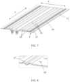
- FIG. 7 is a schematic structural diagram of a buffer structure 27 of the upper cover 51. In a projection in the first direction Z, the buffer structure 27 is located outside the temperature adjustment surface 23, and the buffer structure 27 is configured to provide deformation allowance.
- FIG. 8 is an enlarged diagram of part E in FIG. 7 .
- a mounting hole 28 is formed in the upper cover 51, and the mounting hole 28 is configured to insert a bolt to secure the upper cover 51 and the box housing 52 together.
- the buffer structure 27 is located outside the temperature adjustment surface 23 and inside the mounting hole 28.
- the buffer structure 27 is formed by bending plates forming the upper cover 51, and the buffer structure 27 is wavy. Due to formation of the buffer structure 27 bent in such way, the buffer structure 27 can deform to provide deformation allowance accordingly subsequent when the battery cell 20 swells to deform.
- the buffer structure 27 extends in the third direction Y
- the buffer structure 27 is formed by removing part of formation material of the upper cover 51.
- a slot or a hole is formed in the upper cover 51, and part of the formation material is removed to make such part less rigid and easy to deform.
- the buffer structure 27 includes multiple slots or holes formed in the third direction Y It should be noted that when the buffer structure 27 is a hole, the hole does not run through the whole upper cover 51 to prevent gas generated inside the box from leaking via the hole.
- the upper cover 51 is formed by two plates, the hole is formed only in either one of the plates. Shapes of the slot and hole are not limited. For example, in FIG. 9 , rectangular slots are formed.
- the buffer structure 27 enables the upper cover 51 as a whole to deform in a more adaptive manner when the battery cell 20 swells to deform, thereby improving the overall structural stability and safety of the box 50.
- the box housing 52 may also have such structure.
- the foregoing buffer structure 27 is formed in the upper cover 51 and/or the box housing 52 integrated with the thermal management flow channel.
- the buffer structure 27 can be formed in any component adjacent to the battery cell 20 to provide deformation allowance when the battery cell 20 swells to deform.
- An embodiment of this application further provides an electric apparatus, where the electric apparatus may include the battery 1 in the foregoing embodiments.
- the battery 1 is configured to provide electric energy in the electric apparatus.
- FIG. 7 is a schematic flowchart of a method 400 for preparing battery according to an embodiment of this application. As shown in FIG. 7 , the method 400 may include the following steps:
- a box 50 where the box 50 has an upper cover 51 and a box housing 52, flow channels are formed on the upper cover 51 and the box housing 52, and the flow channel is configured to accommodate fluid.
- the battery units 10 Accommodate the battery units 10 in a space formed by the upper cover 51 and the box housing 52, where in the first direction Z, the battery units 10 include a first battery unit 11 located at a top layer and a second battery unit 12 located at a bottom layer, the upper cover 51 is configured to adjust temperature of the first battery unit 11 via the fluid, and the box housing 52 is configured to adjust temperature of the second battery unit 12 via the fluid.
- FIG. 8 is a schematic block diagram of an apparatus 500 for preparing battery according to an embodiment of this application.
- the apparatus 500 for preparing battery may include:
Landscapes
- Chemical & Material Sciences (AREA)
- Chemical Kinetics & Catalysis (AREA)
- Electrochemistry (AREA)
- General Chemical & Material Sciences (AREA)
- Engineering & Computer Science (AREA)
- Manufacturing & Machinery (AREA)
- Aviation & Aerospace Engineering (AREA)
- Physics & Mathematics (AREA)
- Algebra (AREA)
- General Physics & Mathematics (AREA)
- Mathematical Analysis (AREA)
- Mathematical Optimization (AREA)
- Pure & Applied Mathematics (AREA)
- Secondary Cells (AREA)
- Battery Mounting, Suspending (AREA)
Abstract
Description
- This application relates to the field of energy storage apparatuses, and more specifically, to a battery, an electric apparatus, a method for preparing a battery, and an apparatus for preparing a battery.
- Energy conservation and emission reduction are critical to sustainable development of the automobile industry. Under this situation, due to their advantages in energy conservation and environmental protection, electric vehicles have become an important part for sustainable development of the automobile industry. For electric vehicles, battery technology is an important factor related to their development.
- With continuous development of battery technologies, performance requirements for batteries are getting higher, and batteries are expected to be designed in consideration of various factors.
- This application provides a battery, an electric apparatus, a method for preparing a battery, and an apparatus for preparing a battery, to improve safety of the battery.
- According to a first aspect, a battery is provided, including: at least two layers of battery units arranged in a first direction and a box having an upper cover and a box housing, where the at least two layers of battery units are accommodated in a space formed by the upper cover and the box housing; in the first direction, the at least two layers of battery units include a first battery unit located at a top layer and a second battery unit located at a bottom layer; and flow channels are formed on the upper cover and the box housing, the flow channel is configured to accommodate fluid, the upper cover is configured to adjust temperature of the first battery unit via the fluid, and the box housing is configured to adjust temperature of the second battery unit via the fluid.
- To improve power supply efficiency of the battery, the battery typically has multiple layers of battery units, and each battery unit has multiple battery cells. In this case, thermal management efficiency of multiple layers of battery cells needs to be improved to keep temperature of each layer of battery units within a given range, so that the battery can deliver excellent electrochemical performance.
- In technical solutions of this application, the upper cover and the box housing in the box of the battery each are integrated with a flow channel for thermal management. The upper cover is used to perform thermal management on a battery unit at a top layer, and the box housing is used to perform thermal management on a battery unit at a bottom layer. In this way, a thermal management environment can be formed for the battery by using the upper cover and the box housing, to better perform thermal management on the multiple layers of battery units, thereby improving power supply performance and safety of the battery.
- In some embodiments, the battery includes a connecting pipe, where the connecting pipe is configured to connect the flow channel of the upper cover and the flow channel of the box housing, and the connecting pipe communicates with an external flow channel of the box. This allows the fluid in the flow channel of the upper cover and the fluid in the flow channel of the box housing to join and circulate throughout the box, thereby increasing temperature consistency of the multiple layers of battery cells.
- In some embodiments, the connecting pipe is provided outside the box. Therefore, sealing the flow channels in the upper cover and the box housing can be performed outside the box, improving the sealing performance and safety. In addition, the connecting pipe outside the box is easy to maintain and replace, making operations more convenient.
- In some embodiments, the battery unit includes a battery cell, where the battery cell has an electrode terminal, the electrode terminal is provided on an end surface of the battery cell in a second direction, and the second direction is orthogonal to the first direction. This means that the at least two layers of battery units are arranged in the first direction and electrode terminals of the battery cells in the battery units are arranged towards the second direction. Therefore, in the battery cell, a surface cooled/heated by the upper cover and the box housing is not the end surface provided with the electrode terminal, but a side surface of an electrode monomer. Such arrangement can enlarge the area of the electrode monomer subjected to temperature adjustment by the upper cover and the box housing, thereby improving thermal management efficiency.
- In some embodiments, at least one of the upper cover and the box housing includes multiple flow sub-channels extending in a third direction; a junction channel extending in the second direction, where the junction channel is located on an end of the flow sub-channel in the third direction to connect the multiple flow sub-channels; and a partition, where the flow sub-channel and the partition are arranged alternately in the second direction, the partition is configured to separate two of the flow sub-channels adjacent to the partition, and the third direction is orthogonal to the first direction and the second direction. Such a flow channel and partition structures used in the upper cover and/or the box housing can increase rigidity of the upper cover and/or the box housing and better suppress swelling of the battery cell, thereby increasing overall structural strength of the battery.
- In some embodiments, in the upper cover and/or the box housing, thickness of the partition is less than thickness of the flow sub-channel in the first direction. In the case of failure or overheating, the battery cell will swell and deform, with the side surface deformed more seriously. Therefore, a partition with a small thickness is formed on the upper cover and/or the box housing that performs thermal management on the side surface of the battery cell. Compared with adjacent flow sub-channels, the partition with a small thickness has lower rigidity so that such partition is more likely to deform with swelling of the battery cell. In addition, because of the small thickness, there is still room for swelling, thereby ensuring the safety of the battery. Herein, "the upper cover and/or the box housing" refers to an upper cover and/or a box housing with a partition.
- In some embodiments, the upper cover and/or the box housing includes a concave-convex plate and a flat plate that are opposite each other, where a concave portion of the concave-convex plate tightly fits with the flat plate to form the partition, and the flow channel is formed between a convex portion of the concave-convex plate and the flat plate. Such concave-convex plate and flat plate are easy to form. In addition, the concave-convex plate and the flat plate are combined to make the upper cover and/or the box housing through a simple process, enabling the partition in the upper cover and/or the box housing to have a smaller thickness than its adjacent flow sub-channels easily.
- In some embodiments, the flat plate is closer to the battery unit than the concave-convex plate. Therefore, a surface of the upper cover and/or the box housing facing the battery cell is flat. In this way, height in the first direction can be reduced by using the concave portion of the concave-convex plate to ensure room for swelling, and the thermal management area of the battery cell can be increased by using the flat plate.
- In some embodiments, the battery cell has multiple side surfaces, where in the first direction, a side surface adjacent to the upper cover or the box housing is a temperature adjustment surface whose temperature is adjusted via the fluid.
- In some embodiments, in the multiple side surfaces of the battery cell, the temperature adjustment surface has a largest area. To be specific, the largest side surface of the battery cell in the first battery unit has its temperature adjusted by the fluid in the upper cover, and the largest side surface of the battery cell in the second battery unit has its temperature adjusted by the fluid in the box housing. Temperature adjustment on the largest side surface can improve the thermal management efficiency.
- In some embodiments, in the second direction, the temperature adjustment surface has a central region and lateral regions located on two sides of the central region.
- In some embodiments, in the second direction, a length of the central region is 1/8-1/2 of a length of the temperature adjustment surface, and the central region contains the center of the temperature adjustment surface. The center of the temperature adjustment surface in the second direction is a position at half the length of the temperature adjustment surface in the second direction. When the battery cell deforms, the central region of its temperature adjustment surface seriously deforms.
- In some embodiments, in the upper cover and/or the box housing, the partition is provided opposite the central region in the first direction. To be specific, in the upper cover and/or the box housing with the partition, the central region of the temperature adjustment surface overlaps with the partition in a projection in the first direction. A seriously deformed central region in the temperature adjustment surface is opposite a partition with low rigidity, so that the partition deforms easily with swelling of the central region of the battery cell. In addition, in the first direction, there is room for swelling on at least one side of the partition, so that swelling-induced deformation of the battery cell is not constrained and stress on the upper cover and/or the box housing can be released.
- In some embodiments, in the upper cover and/or the box housing, at least one of the flow channels is provided at a position opposite the lateral region in the first direction. In the upper cover and/or the box housing, the flow channel is more rigid than the partition. In the temperature adjustment surface of the battery cell, the lateral region has less swelling-induced deformation. Then, at least one flow channel is provided at a position opposite the lateral region to increase rigidity at a position of the upper cover and/box housing opposite the lateral region and flexibility at a position opposite the central region. This can avoid affecting the thermal management effect due to the decreased effective thermal management area resulting from an increased distance between the upper cover and/or the box housing and the battery cell after the battery cell swells in the first direction.
- In some embodiments, the upper cover and/or the box housing has a buffer structure, where in a projection in the first direction, the buffer structure is located outside the temperature adjustment surface, and the buffer structure is configured to provide deformation allowance. Therefore, when the battery cell swells to deform, the buffer structure deforms accordingly, thereby providing room for swelling, without limiting the swelling-induced deformation of the battery cell.
- In some embodiments, a thermal management component is formed between any two adjacent layers of battery units, a middle-layer flow channel is formed in the thermal management component, and the middle-layer flow channel is configured to accommodate the fluid to adjust temperature of the two adjacent layers of battery units. To further balance temperature of the battery cell, the upper cover and the box housing each are integrated with a temperature adjustment flow channel, and the thermal management component is further provided between two layers of battery units, so that opposite surfaces of the battery cells in the two layers of battery units can also have temperature adjusted and become interlayer temperature adjustment surfaces.
- In some embodiments, the middle-layer flow channel communicates with the flow channel of the upper cover and the flow channel of the box housing. This allows the fluid in the flow channel of the upper cover, fluid in the flow channel of the box housing, and fluid in the middle-layer flow channel to join and circulate throughout the box, thereby increasing temperature consistency of the multiple layers of battery cells.
- In some embodiments, the thermal management component is bonded to the two adjacent layers of battery units. The thermal management component and the two adjacent layers of battery units are bonded by using an adhesive with good thermal conductivity, so that the thermal management component can be secured to the battery cell, without reducing the thermal management effect due to displacement of the thermal management component. Therefore, temperature adjustment on the two adjacent layers of battery units can be performed stably through a surface bonded to the battery cell, thereby improving thermal management efficiency.
- According to a second aspect, an electric apparatus is provided, including the battery according to the first aspect. The battery is configured to provide electric energy.
- According to a third aspect, a method for preparing a battery is provided, including: providing battery units, where the battery units are arranged in at least two layers in a first direction; providing a box, where the box has an upper cover and a box housing, flow channels are formed on the upper cover and the box housing, and the flow channel is configured to accommodate fluid; and accommodating the battery units in a space formed by the upper cover and the box housing, where in the first direction, the battery units include a first battery unit located at a top layer and a second battery unit located at a bottom layer, the upper cover is configured to adjust temperature of the first battery unit via the fluid, and the box housing is configured to adjust temperature of the second battery unit via the fluid.
- According to a fourth aspect, an apparatus for preparing a battery is provided, including a first provision module, configured to provide battery units, where the battery units are arranged in at least two layers in a first direction; a second provision module, configured to provide a box, where the box has an upper cover and a box housing, flow channels are formed on the upper cover and the box housing, and the flow channel is configured to accommodate fluid; and a mounting module, configured to accommodate the battery units in a space formed by the upper cover and the box housing, where in the first direction, the battery units include a first battery unit located at a top layer and a second battery unit located at a bottom layer, the upper cover is configured to adjust temperature of the first battery unit via the fluid, and the box housing is configured to adjust temperature of the second battery unit via the fluid.
- The accompanying drawings described herein are intended for better understanding of this application, and constitute a part of this application. Exemplary embodiments and descriptions thereof in this application are intended to interpret this application and do not constitute any improper limitation on this application. In the accompanying drawings:
-
FIG. 1 is a schematic diagram of a vehicle according to an embodiment of this application; -
FIG. 2 is a three-dimensional structural diagram of a battery according to an embodiment of this application; -
FIG. 3 is a schematic top view showing a structure of a battery; -
FIG. 4 is a sectional view of part I-I inFIG. 3 ; -
FIG. 5 is an enlarged diagram of part C inFIG. 4 ; -
FIG. 6 is an enlarged diagram of part D inFIG. 4 ; -
FIG. 7 is a schematic diagram of a buffer structure of an upper cover; -
FIG. 8 is an enlarged diagram of part E inFIG. 7 ; -
FIG. 9 is a schematic diagram of another embodiment of a buffer structure; -
FIG. 10 is a schematic flowchart of a method for preparing a battery according to an embodiment of this application; and -
FIG. 11 is a schematic block diagram of an apparatus for preparing a battery according to an embodiment of this application. - To make the objectives, technical solutions, and advantages of the embodiments of this application clearer, the following clearly describes the technical solutions in the embodiments of this application with reference to the accompanying drawings in the embodiments of this application. Apparently, the described embodiments are some but not all of the embodiments of this application. All other embodiments obtained by a person of ordinary skill in the art based on the embodiments of this application without creative efforts shall fall within the protection scope of this application.
- Unless otherwise defined, all technical and scientific terms used in this application shall have the same meanings as commonly understood by those skilled in the art to which this application belongs. The terms used in the specification of this application are merely intended to describe the specific embodiments but not intended to constitute any limitation on this application. The terms "include", "comprise", and any variations thereof in the specification and claims of this application and the foregoing description of the drawings are intended to cover non-exclusive inclusions. In the specification, claims, or accompanying drawings of this application, the terms "first", "second", and the like are intended to distinguish between different objects but do not indicate a particular order or a subordinate relationship.
- An "embodiment" mentioned in this application means that specified features, structures, or characteristics described with reference to this embodiment may be included in at least one embodiment of this application. The word "embodiment" in various positions in the specification does not necessarily refer to a same embodiment, or an independent or alternative embodiment that is exclusive of other embodiments. A person skilled in the art can clearly and implicitly understand that the embodiments described in this application can be combined with other embodiments.
- In the descriptions of this application, it should be noted that unless otherwise specified and defined explicitly, the terms "installment", "link", "connection", and "attachment" should be understood in their general senses. For example, the terms may be a fixed connection, a detachable connection, or an integrated connection, or may be a direct connection, an indirect connection through an intermediate medium, or an internal connection between two elements. A person of ordinary skills in the art can understand specific meanings of these terms in this application based on specific situations.
- The term "and/or" in this application describes only an association relationship for describing associated objects and represents that three relationships may exist. For example, A and/or B may represent the following three cases: A alone, both A and B, and B alone. In addition, the character "/" in this application generally indicates an "or" relationship between the associated objects.
- In this application, "a plurality of" means two (inclusive) or more. Similarly, "a plurality of groups" means two (inclusive) or more groups, and "a plurality of pieces" means two (inclusive) or more pieces.
- The battery mentioned in the embodiments of this application is a single physical module that includes multiple battery cells for providing higher voltage and capacity. For example, the battery mentioned in this application may include a battery module, a battery pack, or the like.
- The battery cell includes an electrode assembly and an electrolyte. The electrode assembly includes a positive electrode plate, a negative electrode plate, and a separator. The battery cell functions mainly relying on migration of metal ions between the positive electrode plate and the negative electrode plate. The positive electrode plate includes a positive electrode current collector and a positive electrode active substance layer. A surface of the positive electrode current collector is coated with the positive electrode active substance layer. A positive electrode current collector not coated with the positive electrode active substance layer bulges out of a positive electrode current collector coated with the positive electrode active substance layer, and the positive electrode current collector not coated with the positive electrode active substance layer is used as a positive tab. A lithium-ion battery is used as an example. A positive electrode current collector may be made of aluminum and a positive electrode active material may be lithium cobaltate, lithium iron phosphate, ternary lithium, lithium manganate, or the like. The negative electrode plate includes a negative electrode current collector and a negative electrode active substance layer. A surface of the negative electrode current collector is coated with the negative electrode active substance layer. A negative electrode current collector not coated with the negative electrode active substance layer bulges out of a negative electrode current collector coated with the negative electrode active substance layer, and the negative electrode current collector not coated with the negative electrode active substance layer is used as a negative tab. The negative electrode current collector may be made of copper, and a negative electrode active substance may be carbon, silicon, or the like. To allow a large current to pass through without any fusing, multiple positive tabs are provided and stacked together, and multiple negative tabs are provided and stacked together. The separator may be made of PP, PE, or the like. In addition, the electrode assembly may have a winding structure or a laminated structure. The embodiments of this application are not limited thereto.
- The development of battery technologies relates to many design factors, for example, performance parameters such as energy density, cycle life, discharge capacity, and charge and discharge rate. Safety of batteries also needs to be considered.
- At present, a battery of an electric vehicle often requires tens or even hundreds of battery cells. To improve power supply efficiency of the battery, the battery typically has multiple layers of battery units arranged in one direction, and each battery unit has a battery cell. In this case, thermal management efficiency of multiple layers of battery cells needs to be improved to maintain temperature of each layer of battery units, so as to keep temperature of the battery in a performance comfort zone and prevent thermal runaway caused by overheating.
- In view of this, this application provides a battery, including: at least two layers of battery units arranged in a first direction and a box having an upper cover and a box housing, where the at least two layers of battery units are accommodated in a space formed by the upper cover and the box housing; in the first direction, the at least two layers of battery units include a first battery unit located at a top layer and a second battery unit located at a bottom layer; and flow channels are formed on the upper cover and the box housing, the flow channel is configured to accommodate fluid, the upper cover is configured to adjust temperature of the first battery unit via the fluid, and the box housing is configured to adjust temperature of the second battery unit via the fluid.
- The upper cover and the box housing in the box each are integrated with a thermal management flow channel, so that the upper cover can be used to perform thermal management on a battery unit at a top layer, and the box housing can be used to perform thermal management on a battery unit at a bottom layer. In this way, a thermal management environment can be formed for the battery by using the upper cover and the box housing, to better perform thermal management on the multiple layers of battery units, thereby improving power supply performance and safety of the battery.
- An embodiment of this application provides an electric apparatus, and a battery is configured to provide electric energy.
- The technical solutions described in the embodiments of this application are applicable to various apparatuses that use batteries, such as mobile phones, portable devices, notebook computers, electric bicycles, electric toys, electric tools, electric vehicles, ships, and spacecraft. For example, spacecraft include airplanes, rockets, space shuttles, and spaceships.
- It should be understood that the technical solutions described in the embodiments of this application are not only applicable to the apparatuses described above, but also applicable to all apparatuses using batteries. However, for brevity of description, in the following embodiments, the vehicle is used as an example for description.
- For example,
FIG. 1 is a schematic structural diagram of avehicle 100 according to an embodiment of this application. Thevehicle 100 may be a fuel vehicle, a gas vehicle, or a new energy vehicle, and the new energy vehicle may be a battery electric vehicle, a hybrid electric vehicle, an extended range electric vehicle, or the like. Amotor 2, acontroller 3, and abattery 1 may be disposed inside thevehicle 100, and thecontroller 3 is configured to control thebattery 1 to supply power to themotor 2. For example, thebattery 1 may be disposed at the bottom, the front, or the rear of thevehicle 100. Thebattery 1 may be configured to supply power to thevehicle 100. For example, thebattery 1 may be used as an operational power supply for thevehicle 100, and may be applied to a circuit system of thevehicle 100, for example, may be configured to supply power to meet the start, navigation, and driving requirements of thevehicle 100. In another embodiment of this application, thebattery 1 not only can be used as the operational power supply for thevehicle 100, but also can be used as a driving power supply for thevehicle 100, to totally or partially replace fossil fuel or natural gas to provide driving power for thevehicle 100. - As shown in
FIG. 2 , to meet different power usage requirements, thebattery 1 may include multiple layers ofbattery units 10 arranged in a first direction Z, where thebattery unit 10 hasmultiple battery cells 20, and themultiple battery cells 20 may be connected in series, in parallel, or in series and parallel, and being connected in series and parallel means a combination of series and parallel connections. - For example,
FIG. 2 is a three-dimensional structural diagram of abattery 1 according to an embodiment of this application. Thebattery 1 includes abox 50, the inside of thebox 50 is a hollow structure, and thebattery unit 10 is accommodated in thebox 50. Thebattery unit 10 has thebattery cell 20. As shown inFIG. 2 , thebox 50 may include two parts, which are referred to herein as anupper cover 51 and abox housing 52 respectively. Theupper cover 51 and thebox housing 52 are snap-fitted. Shapes of theupper cover 51 and thebox housing 52 may be determined depending on a shape in which themultiple battery cells 20 are combined. For example, theupper cover 51 and thebox housing 52 each may be a hollow cuboid and have only one surface with an opening, the opening of theupper cover 51 is disposed opposite the opening of thebox housing 52, and theupper cover 51 and thebox housing 52 are snap-fitted to form thebox 50 with an enclosed chamber. Alternatively, theupper cover 51 is a cuboid with an opening and thebox housing 52 is in a plate shape, or thebox housing 52 is a cuboid with an opening and theupper cover 51 is in a plate shape, and theupper cover 51 and thebox housing 52 are disposed opposite each other and snap-fitted to form thebox 50 with an enclosed chamber. - As shown in
FIG. 2 , the multiple layers ofbattery units 10 arranged in the first direction Z are accommodated in thebox 50, and themultiple battery cells 20 in eachbattery unit 10 can be arranged in a second direction X and a third direction Y, where the second direction X is orthogonal to the third direction Y, and both the second direction X and the third direction Y are orthogonal to the first direction Z. This means that themultiple battery cells 20 in thebattery unit 10 may be arranged in a matrix structure. Themultiple battery cells 20 are connected in parallel or in series or in parallel and series, and then placed into thebox housing 50 formed after theupper cover 51 and thebox housing 52 are snap-fitted. Optionally, eachbattery unit 10 may have only onebattery cell 20. - As shown in
FIG. 2 , thebattery 1 includes at least two layers ofbattery units 10 arranged in the first direction Z and thebox 50 having theupper cover 51 and thebox housing 52, where the at least two layers ofbattery units 10 are accommodated in a space formed by theupper cover 51 and thebox housing 52; in the first direction Z, the at least two layers ofbattery units 10 include afirst battery unit 11 located at a top layer and asecond battery unit 12 located at a bottom layer; and flowchannels 30 are formed on theupper cover 51 and thebox housing 52, theflow channel 30 is configured to accommodate fluid, theupper cover 51 is configured to adjust temperature of thefirst battery unit 11 via the fluid, and thebox housing 52 is configured to adjust temperature of thesecond battery unit 12 via the fluid. - In
FIG. 2 , thebattery 1 includes two layers ofbattery units 10. Thebattery 1 may alternatively have three or more layers ofbattery units 10. - Under the condition that the
battery 1 has multiple layers ofbattery units 10, thermal management efficiency of the multiple layers ofbattery units 10 needs to be improved to keep temperature of each layer ofbattery units 10 within a given range, so that thebattery 1 can deliver excellent electrochemical performance. In this application, theupper cover 51 and thebox housing 52 in thebox 50 each are integrated with a thermal management flow channel, so that theupper cover 51 is used to perform thermal management on afirst battery unit 11 at the top layer, and thebox housing 52 is used to perform thermal management on asecond battery unit 12 at the bottom layer. In this way, a thermal management environment can be formed for thebattery 1 by using theupper cover 51 and thebox housing 52, to better perform thermal management on the multiple layers ofbattery units 10, thereby improving power supply performance and safety of thebattery 1. - In this application, the
upper cover 51 and thebox housing 52 that are integrated with a thermal management flow channel have thermal management function, and fluid is accommodated in theupper cover 51 and thebox housing 52 to adjust temperature of thebattery cell 20. The fluid herein may be liquid or gas. Adjusting temperature means heating or cooling thebattery cell 20. In a case of cooling down or lowering the temperature of thebattery cell 20, theupper cover 51 and thebox housing 52 are configured to accommodate a cooling fluid to lower the temperature of thebattery cell 20, the fluid accommodated therein may also be referred to as a cooling medium or cooling fluid, and more specifically, a cooling liquid or cooling gas. In addition, theupper cover 51 and thebox housing 52 may also be used for heating to increase the temperature of thebattery cell 20, which is not limited in the embodiments of this application. - In some embodiments, the fluid may circulate to achieve a better temperature adjustment effect.
- In some embodiments, the fluid may be water, mixed liquid of water and glycol, air, or the like.
- As shown in
FIG. 2 , thebattery 1 includes a connectingpipe 60, where the connectingpipe 60 is configured to connect theflow channel 30 of theupper cover 51 and theflow channel 30 of thebox housing 52, and the connectingpipe 60 communicates with an external flow channel of thebox 50. This allows the fluid in theflow channel 30 of theupper cover 51 and the fluid in theflow channel 30 of thebox housing 52 to join and circulate throughout thebox 50, thereby increasing temperature consistency of the multiple layers ofbattery units 10. - In some embodiments, as shown in
FIG. 2 , the connectingpipe 60 is provided outside thebox 50. Therefore, sealing flow channels can be performed outside thebox 50, thereby improving the sealing performance and safety. In addition, the connectingpipe 60 outside thebox 50 is easy to maintain and replace, making operations more convenient. - In
FIG. 2 , thefirst battery unit 11 and thesecond battery unit 12 each includemultiple battery cells 20, and thebattery cell 20 has anelectrode terminal 21, where theelectrode terminal 21 is provided on anend surface 22 of thebattery cell 20 in a second direction X.FIG. 2 shows a structure that twoelectrode terminals 21 are provided on oneend surface 22. However, this is not limited. Theelectrode terminal 21 may also be provided on theother end surface 22 opposite theend surface 22 in the second direction X. - The
first battery unit 11 and thesecond battery unit 12 are arranged in the first direction Z, and theelectrode terminals 21 of thebattery cells 20 in thefirst battery unit 11 and thesecond battery unit 12 are all disposed towards the second direction. Therefore, as shown inFIG. 2 , in thebattery cell 20, a surface cooled/heated by theupper cover 51 and thebox housing 52 is not theend surface 22 provided with the electrode terminal 21 (and theother end surface 22 opposite theend surface 22 in the second direction X), but a side surface of anelectrode monomer 10 other than the two end surfaces 22. - Among the side surfaces of the
battery cell 20, the side surface adjacent to theupper cover 51 or thebox housing 52 in the first direction Z is atemperature adjustment surface 23 whose temperature is adjusted via the fluid. - In some embodiments, as shown in
FIG. 2 , thetemperature adjustment surface 23 has a largest area among the side surfaces of thebattery cell 20. Thus, thetemperature adjustment surface 23 of thebattery cell 20 in thefirst battery unit 11 has its temperature adjusted by theupper cover 51, and thetemperature adjustment surface 23 of thebattery cell 20 in thesecond battery unit 12 has its temperature adjusted by thebox housing 52. Temperature adjustment on the largest side surface can increase the area of thebattery cell 20 subjected to thermal management by theupper cover 51 and thebox housing 52, thereby improving the thermal management efficiency. -
FIG. 3 is a schematic top view showing a structure of thebattery 1. Thebox housing 52 may also have the same flow channel structure.FIG. 3 shows a state that twobattery cells 20 are arranged in thebattery unit 10 in the first direction X. This is also applicable to the following figures. However, thebattery unit 10 is not limited thereto. Thebattery unit 10 may have one ormore battery cells 20 provided in the first direction X. - As shown in
FIG. 3 and FIG. 4 , theupper cover 51 includes multiple flow sub-channels 31 extending in the third direction Y; ajunction channel 32 extending in the second direction X, where thejunction channel 32 is located on an end of theflow sub-channel 31 in the third direction Y to connect the multiple flow sub-channels 31; and apartition 33, where theflow sub-channel 31 and thepartition 33 are arranged alternately in the second direction X, thepartition 33 is configured to separate the two flow sub-channels 31 adjacent to thepartition 33, and the third direction Y is orthogonal to the first direction Z and the second direction X. Theflow channel 30 of theupper cover 51 is composed of theflow sub-channel 31 and thejunction channel 32. Such structures of theflow channel 30 of theupper cover 51 and thepartition 33 can increase rigidity of theupper cover 51 and better suppress swelling of thebattery cell 20, thereby increasing the overall structural strength of thebattery 1. -
FIG. 4 is a sectional view of part I-I inFIG. 3 .FIG. 5 is an enlarged diagram of part C inFIG. 4 . The following describes in detail the structure of theupper cover 51. Thebox housing 52 may have a same structure as theupper cover 51. - As shown in
FIG. 4 , in theupper cover 51, thickness of thepartition 33 is less than that of any portion other than thepartition 33. Thepartition 33 with a smaller thickness is formed in theupper cover 51, and thepartition 33 is less rigid than other portions, so thatsuch partition 33 is more likely to deform with swelling of thebattery cell 20. In addition, because of the smaller thickness of thepartition 33, there is still room for swelling, without affecting circulation of fluid due to theflow channel 30 being crushed and blocked after theupper cover 51 experiences swelling force. - To implement such function, it is only required that the thickness of the
partition 33 be less than the thickness of other portions of theupper cover 51. The structures of theupper cover 51 shown inFIG. 4 andFIG. 5 are examples of such thickness relationship. InFIG. 4 andFIG. 5 , theupper cover 51 includes a concave-convex plate 53 and aflat plate 54 that are opposite each other, where aconcave portion 56 of the concave-convex plate 53 tightly fits with theflat plate 54 to form thepartition 33, and theflow channel 30 of theupper cover 51 is formed between aconvex portion 55 of the concave-convex plate 53 and theflat plate 54. Such concave-convex plate 53 andflat plate 54 are easy to form. In addition, the concave-convex plate 53 and theflat plate 54 are combined to make theupper cover 51 through a simple process, and thepartition 33 in theupper cover 51 can be easily made thinner than theflow sub-channel 31. - In some embodiments, the
flat plate 54 is closer to thebattery unit 10 than the concave-convex plate 53, and the surface of theupper cover 51 facing thebattery cell 20 is flat, so that theconcave portion 56 of the concave-convex plate 53 can be used to reduce the height in the first direction Z and ensure room for swelling, and theflat plate 54 can be used to increase the thermal management area of thebattery cell 20. - In the second direction X, the
temperature adjustment surface 23 has a central region A and lateral regions B located on two sides of the central region A. - In the second direction X, a length L1 of the central region A is 1/8-1/2 of a length L of the
temperature adjustment surface 23, and the central region A contains the center O of thetemperature adjustment surface 23. The center O of thetemperature adjustment surface 23 is a position at half the length of thetemperature adjustment surface 23 in the second direction X. When thebattery cell 20 swells to deform, the central region A of itstemperature adjustment surface 23 seriously deforms. - In the
upper cover 51, thepartition 33 is provided opposite the central region A in the first direction Z. This means that the central region A of thetemperature adjustment surface 23 overlaps with thepartition 33 in a projection in the first direction Z. The seriously deformed central region A in thetemperature adjustment surface 23 is opposite thepartition 33 with low rigidity, so that thepartition 33 is easy to deform with swelling of the central region A of thebattery cell 20. In addition, in the first direction Z, there is room for swelling on at least one side of thepartition 33, so that swelling-induced deformation of thebattery cell 20 is not constrained and stress on theupper cover 51 can be released. - In some embodiments, length of the
partition 33 may be greater than or equal to that of the central region A. - In the
upper cover 51, at least oneflow channel 30 is provided at a position opposite the lateral region B in the first direction Z. The part of theupper cover 51 provided with theflow channel 30 is more rigid than thepartition 33. However, in thetemperature adjustment surface 23 of thebattery cell 20, the lateral region B has less swelling-induced deformation. Then, at least oneflow channel 30 is provided at a position opposite the lateral region B increase rigidity at a position of theupper cover 51 opposite the lateral region B and flexibility at a position opposite the central region A. This can avoid affecting the thermal management effect due to the decreased effective thermal management area resulting from an increased distance between theupper cover 51 and thebattery cell 20 after thebattery cell 20 swells in the first direction Z. - In
FIG. 4 , theupper cover 51 and thebox housing 52 both have the structure with the foregoing characteristics. However, it is only required that at least one of theupper cover 51 and thebox housing 52 have such structure. -
FIG. 4 also shows a structure that athermal management component 70 is formed between the adjacentfirst battery unit 11 andsecond battery unit 12.FIG. 6 is an enlarged diagram of part D inFIG. 4 . A middle-layer flow channel 71 is formed in thethermal management component 70, and the middle-layer flow channel 71 is configured to accommodate fluid to adjust temperature of the adjacentfirst battery unit 11 andsecond battery unit 12. In this case, theupper cover 51 and thebox housing 52 each are integrated with aflow channel 30 for temperature adjustment, and thethermal management component 70 is also provided between the two adjacent layers ofbattery units 10, so that opposite surfaces of thebattery cells 20 in the two adjacent layers ofbattery units 10 can have temperature adjusted and become interlayer temperature adjustment surfaces. This can improve the thermal management efficiency and further balance temperature of thebattery cell 20. - The middle-
layer flow channel 71 can connect theflow channel 30 of theupper cover 51 and theflow channel 30 of thebox housing 52, allowing fluid in theflow channel 30 of theupper cover 51, fluid in theflow channel 30 of thebox housing 52, and fluid in the middle-layer flow channel 71 to join and circulate throughout thebox 50, thereby increasing temperature consistency of the multiple layers ofbattery units 10. - Two end surfaces of the
thermal management component 70 in the first direction Z are bonded to the respectiveadjacent battery cells 20, and the two end surfaces of thethermal management component 70 may be flat surfaces to increase bonding reliability. Thethermal management component 70 is bonded to thebattery cells 20 in theadjacent battery units 10 by using an adhesive with good thermal conductivity. Temperature adjustment on the two adjacent layers ofbattery units 10 can be well performed through the surfaces bonded to thebattery cells 20, which, in conjunction with the temperature adjustment by theupper cover 51 and thebox housing 52, can greatly improve the thermal management efficiency. - The
thermal management component 70 is bonded to thebattery cells 20 in theadjacent battery units 10 by using an adhesive with good thermal conductivity, so that thethermal management component 70 can be secured to thebattery unit 10, preventing from compromising the thermal management effect due to displacement of thethermal management component 70. Therefore, temperature adjustment on the two adjacent layers ofbattery units 10 can be stably performed through the surface bonded to thebattery cell 20, thereby improving the thermal management efficiency. -
FIG. 4 andFIG. 6 show a structure that thebattery 1 has two layers ofbattery units 10 and thethermal management component 70 is provided between the two layers ofbattery units 10. When thebattery 1 has three or more layers ofbattery units 10, thethermal management component 70 can be provided between any two adjacent layers ofbattery units 10 in the foregoing manner. -
FIG. 7 is a schematic structural diagram of abuffer structure 27 of theupper cover 51. In a projection in the first direction Z, thebuffer structure 27 is located outside thetemperature adjustment surface 23, and thebuffer structure 27 is configured to provide deformation allowance.FIG. 8 is an enlarged diagram of part E inFIG. 7 . - As shown in
FIG. 7 and FIG. 8 , a mountinghole 28 is formed in theupper cover 51, and the mountinghole 28 is configured to insert a bolt to secure theupper cover 51 and thebox housing 52 together. In a projection in the first direction Z, thebuffer structure 27 is located outside thetemperature adjustment surface 23 and inside the mountinghole 28. InFIG. 7 and FIG. 8 , thebuffer structure 27 is formed by bending plates forming theupper cover 51, and thebuffer structure 27 is wavy. Due to formation of thebuffer structure 27 bent in such way, thebuffer structure 27 can deform to provide deformation allowance accordingly subsequent when thebattery cell 20 swells to deform. As shown inFIG. 7 , thebuffer structure 27 extends in the third direction Y - In some embodiments, as shown in
FIG. 9 , thebuffer structure 27 is formed by removing part of formation material of theupper cover 51. For example, a slot or a hole is formed in theupper cover 51, and part of the formation material is removed to make such part less rigid and easy to deform. As shown inFIG. 9 , thebuffer structure 27 includes multiple slots or holes formed in the third direction Y It should be noted that when thebuffer structure 27 is a hole, the hole does not run through the wholeupper cover 51 to prevent gas generated inside the box from leaking via the hole. For example, when theupper cover 51 is formed by two plates, the hole is formed only in either one of the plates. Shapes of the slot and hole are not limited. For example, inFIG. 9 , rectangular slots are formed. - The
buffer structure 27 enables theupper cover 51 as a whole to deform in a more adaptive manner when thebattery cell 20 swells to deform, thereby improving the overall structural stability and safety of thebox 50. - In
FIG. 7 andFIG. 9 , only theupper cover 51 has the structure with the foregoing characteristics. However, thebox housing 52 may also have such structure. - The design of the
upper cover 51 has been detailed in the foregoing embodiments. It can be understood that thebox housing 52 can also be designed as above. - In this application, the foregoing
buffer structure 27 is formed in theupper cover 51 and/or thebox housing 52 integrated with the thermal management flow channel. However, thebuffer structure 27 can be formed in any component adjacent to thebattery cell 20 to provide deformation allowance when thebattery cell 20 swells to deform. - An embodiment of this application further provides an electric apparatus, where the electric apparatus may include the
battery 1 in the foregoing embodiments. Thebattery 1 is configured to provide electric energy in the electric apparatus. - The battery and the electric apparatus in the embodiments of this application are described above, and a method and an apparatus for preparing battery in the embodiments of this application are described below. For content that is not described in detail, refer to the foregoing embodiments.
-
FIG. 7 is a schematic flowchart of amethod 400 for preparing battery according to an embodiment of this application. As shown inFIG. 7 , themethod 400 may include the following steps: - 410. Provide
battery units 10, where thebattery units 10 are arranged in at least two layers in a first direction Z. - 420. Provide a
box 50, where thebox 50 has anupper cover 51 and abox housing 52, flow channels are formed on theupper cover 51 and thebox housing 52, and the flow channel is configured to accommodate fluid. - 430. Accommodate the
battery units 10 in a space formed by theupper cover 51 and thebox housing 52, where in the first direction Z, thebattery units 10 include afirst battery unit 11 located at a top layer and asecond battery unit 12 located at a bottom layer, theupper cover 51 is configured to adjust temperature of thefirst battery unit 11 via the fluid, and thebox housing 52 is configured to adjust temperature of thesecond battery unit 12 via the fluid. -
FIG. 8 is a schematic block diagram of anapparatus 500 for preparing battery according to an embodiment of this application. As shown inFIG. 8 , theapparatus 500 for preparing battery may include: - a
first provision module 510, configured to providebattery units 10, where thebattery units 10 are arranged in at least two layers in a first direction Z; - a
second provision module 520, configured to provide abox 50, where thebox 50 has anupper cover 52 and abox housing 52, flow channels are formed on theupper cover 51 and thebox housing 52, and the flow channel is configured to accommodate fluid; and - a mounting
module 530, configured to accommodate thebattery units 10 in a space formed by theupper cover 51 and thebox housing 52; - where in the first direction Z, the
battery units 10 include afirst battery unit 11 located at a top layer and asecond battery unit 12 located at a bottom layer; and theupper cover 51 is configured to adjust temperature of thefirst battery unit 11 via the fluid, and thebox housing 52 is configured to adjust temperature of thesecond battery unit 12 via the fluid. - In conclusion, it should be noted that the foregoing embodiments are merely intended for describing the technical solutions of this application, but not for limiting this application. Although this application is described in detail with reference to the foregoing embodiments, persons of ordinary skills in the art should understand that they may still make modifications to the technical solutions described in the foregoing embodiments or make equivalent replacements to some technical features thereof, without departing from the spirit and scope of the technical solutions of the embodiments of this application.
Claims (21)
- A battery, comprising:at least two layers of battery units arranged in a first direction, anda box having an upper cover and a box housing;wherein the at least two layers of battery units are accommodated in a space formed by the upper cover and the box housing;in the first direction, the at least two layers of battery units comprise a first battery unit located at a top layer and a second battery unit located at a bottom layer; andflow channels are formed on the upper cover and the box housing, the flow channel is configured to accommodate fluid, the upper cover is configured to adjust temperature of the first battery unit via the fluid, and the box housing is configured to adjust temperature of the second battery unit via the fluid.
- The battery according to claim 1, wherein
the battery comprises a connecting pipe, wherein the connecting pipe is configured to connect the flow channel of the upper cover and the flow channel of the box housing, and the connecting pipe communicates with an external flow channel of the box. - The battery according to claim 2, wherein
the connecting pipe is provided outside the box. - The battery according to any one of claims 1 to 3, wherein
the battery unit comprises a battery cell, wherein the battery cell has an electrode terminal, the electrode terminal is provided on an end surface of the battery cell in a second direction, and the second direction is orthogonal to the first direction. - The battery according to claim 4, wherein
at least one of the upper cover and the box housing comprises multiple flow sub-channels extending in a third direction; a junction channel extending in the second direction, wherein the junction channel is located on an end of the flow sub-channel in the third direction to connect the multiple flow sub-channels; and a partition, wherein the flow sub-channel and the partition are arranged alternately in the second direction, the partition is configured to separate two of the flow sub-channels adjacent to the partition, and the third direction is orthogonal to the first direction and the second direction. - The battery according to claim 5, wherein
in the upper cover and/or the box housing, thickness of the partition is less than thickness of the flow sub-channel in the first direction. - The battery according to claim 5 or 6, whereinthe upper cover and/or the box housing has a concave-convex plate and a flat plate that are opposite each other, whereina concave portion of the concave-convex plate tightly fits with the flat plate to form the partition, and the flow channel is formed between a convex portion of the concave-convex plate and the flat plate.
- The battery according to claim 7, wherein
the flat plate is closer to the battery unit than the concave-convex plate. - The battery according to any one of claims 5 to 8, wherein
the battery cell has multiple side surfaces, wherein in the first direction, a side surface adjacent to the upper cover or the box housing is a temperature adjustment surface whose temperature is adjusted via the fluid. - The battery according to claim 9, wherein
in the multiple side surfaces of the battery cell, the temperature adjustment surface has a largest area. - The battery according to claim 9 or 10, wherein
in the second direction, the temperature adjustment surface has a central region and lateral regions located on two sides of the central region. - The battery according to claim 11, wherein
in the second direction, a length of the central region is 1/8-1/2 of a length of the temperature adjustment surface, and the central region contains the center of the temperature adjustment surface. - The battery according to claim 11 or 12, wherein
in the upper cover and/or the box housing, the partition is provided opposite the central region in the first direction. - The battery according to any one of claims 11 to 13, wherein
in the upper cover and/or the box housing, at least one of the flow channels is provided at a position opposite the lateral region in the first direction. - The battery according to any one of claims 11 to 14, wherein
the upper cover and/or the box housing has a buffer structure, wherein in a projection in the first direction, the buffer structure is located outside the temperature adjustment surface, and the buffer structure is configured to provide deformation allowance. - The battery according to any one of claims 1 to 15, wherein
a thermal management component is formed between any two adjacent layers of battery units, a middle-layer flow channel is formed in the thermal management component, and the middle-layer flow channel is configured to accommodate the fluid to adjust temperature of the two adjacent layers of battery units. - The battery according to claim 16, wherein
the middle-layer flow channel communicates with the flow channel of the upper cover and the flow channel of the box housing. - The battery according to claim 16 or 17, wherein
the thermal management component is bonded to the two adjacent layers of battery units. - An electric apparatus, comprising the battery according to any one of claims 1 to 18, wherein the battery is configured to provide electric energy.
- A method for preparing battery, comprising:providing battery units, wherein the battery units are arranged in at least two layers in a first direction,providing a box, wherein the box has an upper cover and a box housing, flow channels are formed on the upper cover and the box housing, and the flow channel is configured to accommodate fluid; andaccommodating the battery units in a space formed by the upper cover and the box housing, wherein in the first direction, the battery units comprise a first battery unit located at a top layer and a second battery unit located at a bottom layer, the upper cover is configured to adjust temperature of the first battery unit via the fluid, and the box housing is configured to adjust temperature of the second battery unit via the fluid.
- An apparatus for preparing battery, comprising:a first provision module, configured to provide battery units, wherein the battery units are arranged in at least two layers in a first direction;a second provision module, configured to provide a box, wherein the box has an upper cover and a box housing, flow channels are formed on the upper cover and the box housing, and the flow channel is configured to accommodate fluid; anda mounting module, configured to accommodate the battery units in a space formed by the upper cover and the box housing;wherein in the first direction, the battery units comprise a first battery unit located at a top layer and a second battery unit located at a bottom layer, the upper cover is configured to adjust temperature of the first battery unit via the fluid, and the box housing is configured to adjust temperature of the second battery unit via the fluid.
Applications Claiming Priority (1)
| Application Number | Priority Date | Filing Date | Title |
|---|---|---|---|
| PCT/CN2021/109918 WO2023004831A1 (en) | 2021-07-30 | 2021-07-30 | Battery, electrical device, method for preparing battery, and device for preparing battery |
Publications (2)
| Publication Number | Publication Date |
|---|---|
| EP4148867A1 true EP4148867A1 (en) | 2023-03-15 |
| EP4148867A4 EP4148867A4 (en) | 2023-11-01 |
Family
ID=85038282
Family Applications (1)
| Application Number | Title | Priority Date | Filing Date |
|---|---|---|---|
| EP21929450.1A Pending EP4148867A4 (en) | 2021-07-30 | 2021-07-30 | BATTERY, ELECTRICAL DEVICE, METHOD FOR PRODUCING A BATTERY AND APPARATUS FOR PRODUCING A BATTERY |
Country Status (6)
| Country | Link |
|---|---|
| US (1) | US12500288B2 (en) |
| EP (1) | EP4148867A4 (en) |
| JP (1) | JP7522221B2 (en) |
| KR (1) | KR102875257B1 (en) |
| CN (1) | CN116830358A (en) |
| WO (1) | WO2023004831A1 (en) |
Families Citing this family (5)
| Publication number | Priority date | Publication date | Assignee | Title |
|---|---|---|---|---|
| CN217158406U (en) | 2022-01-12 | 2022-08-09 | 宁德时代新能源科技股份有限公司 | Battery package and electric device |
| CN116231159B (en) * | 2023-05-06 | 2023-09-01 | 宁德时代新能源科技股份有限公司 | Battery and electricity utilization device |
| US20250202016A1 (en) * | 2023-12-15 | 2025-06-19 | Volvo Car Corporation | Carrier unit for a battery module |
| CN120109410B (en) * | 2025-04-17 | 2025-08-08 | 宁德时代新能源科技股份有限公司 | Battery device and electric equipment |
| CN120300399B (en) * | 2025-06-11 | 2025-08-26 | 宁德时代新能源科技股份有限公司 | Battery devices, power consumption devices and energy storage devices |
Family Cites Families (20)
| Publication number | Priority date | Publication date | Assignee | Title |
|---|---|---|---|---|
| CA2812198C (en) * | 2010-10-04 | 2019-12-31 | Dana Canada Corporation | Conformal fluid-cooled heat exchanger for battery |
| KR101956645B1 (en) | 2011-10-26 | 2019-03-11 | 스미도모쥬기가이고교 가부시키가이샤 | Shovel |
| US9627724B2 (en) * | 2014-12-04 | 2017-04-18 | Lg Chem, Ltd. | Battery pack having a cooling plate assembly |
| KR102731553B1 (en) * | 2016-12-15 | 2024-11-18 | 현대자동차주식회사 | Battery module having cooling structure |
| US11611119B2 (en) * | 2017-04-10 | 2023-03-21 | Yun Energy Limited Company | Battery module, battery device, and battery system having thermal management design |
| KR102258816B1 (en) * | 2017-06-27 | 2021-05-31 | 주식회사 엘지에너지솔루션 | Battery Module |
| KR102391984B1 (en) * | 2018-05-23 | 2022-04-27 | 주식회사 엘지에너지솔루션 | Cooling member for battery module and battery pack including the same |
| FR3085469B1 (en) * | 2018-08-31 | 2022-12-16 | Hutchinson | THERMAL MANAGEMENT STRUCTURE WITH INTEGRATED CHANNELS |
| KR102330377B1 (en) * | 2018-10-12 | 2021-11-22 | 주식회사 엘지에너지솔루션 | Battery module, battery rack comprising the battery module, and energy storage system comprising the battery rack |
| CN209447945U (en) | 2018-12-30 | 2019-09-27 | 宁德时代新能源科技股份有限公司 | A kind of battery pack |
| US20200251698A1 (en) * | 2019-01-31 | 2020-08-06 | Ford Global Technologies, Llc | Multi-tiered battery pack and liquid coolant communication method for same |
| KR102872962B1 (en) * | 2019-05-16 | 2025-10-20 | 현대자동차주식회사 | Battery cooling system for vehicle |
| CN112117398B (en) * | 2019-06-21 | 2022-03-18 | 比亚迪股份有限公司 | vehicle |
| GB2588910A (en) * | 2019-11-13 | 2021-05-19 | Rolls Royce Plc | Battery thermal regulating unit |
| KR102574517B1 (en) * | 2019-11-29 | 2023-09-04 | 삼성에스디아이 주식회사 | Battery pack |
| CN113036256B (en) * | 2019-12-05 | 2022-11-11 | 比亚迪股份有限公司 | Battery pack and electric vehicle |
| CN213366661U (en) * | 2020-08-31 | 2021-06-04 | 恒大新能源技术(深圳)有限公司 | Battery module structure and battery package |
| EP4498481A1 (en) * | 2023-07-22 | 2025-01-29 | DEUTZ Aktiengesellschaft | Housing |
| FR3154350A1 (en) * | 2023-10-24 | 2025-04-25 | Thermal Products France | Dual thermally controlled electrical energy storage device and associated vehicle. |
| US20250158158A1 (en) * | 2023-11-14 | 2025-05-15 | RASCO d.o.o. | Module battery cooling system |
-
2021
- 2021-07-30 EP EP21929450.1A patent/EP4148867A4/en active Pending
- 2021-07-30 JP JP2022561577A patent/JP7522221B2/en active Active
- 2021-07-30 CN CN202180091987.0A patent/CN116830358A/en active Pending
- 2021-07-30 WO PCT/CN2021/109918 patent/WO2023004831A1/en not_active Ceased
- 2021-07-30 KR KR1020227034020A patent/KR102875257B1/en active Active
-
2022
- 2022-09-28 US US17/935,937 patent/US12500288B2/en active Active
Also Published As
| Publication number | Publication date |
|---|---|
| KR20230019247A (en) | 2023-02-07 |
| JP7522221B2 (en) | 2024-07-24 |
| WO2023004831A1 (en) | 2023-02-02 |
| US12500288B2 (en) | 2025-12-16 |
| KR102875257B1 (en) | 2025-10-22 |
| CN116830358A (en) | 2023-09-29 |
| US20230032539A1 (en) | 2023-02-02 |
| JP2023541743A (en) | 2023-10-04 |
| EP4148867A4 (en) | 2023-11-01 |
Similar Documents
| Publication | Publication Date | Title |
|---|---|---|
| US12500288B2 (en) | Battery, electric apparatus, method for preparing battery, and apparatus for preparing battery | |
| US20230327264A1 (en) | Battery module, battery, power consumption device, and method and device for producing battery | |
| US20250055063A1 (en) | Thermal management assembly, battery, and electric apparatus | |
| KR102911130B1 (en) | Batteries, electrical devices, battery manufacturing methods and devices | |
| JP7470136B2 (en) | HEAT EXCHANGE MEMBER AND ITS MANUFACTURING METHOD, MANUFACTURING SYSTEM, BATTERY AND ELECTRIC DEVICE | |
| JP7594010B2 (en) | Batteries, power consuming devices, battery manufacturing methods and devices | |
| US20240421435A1 (en) | Battery cell, battery module, battery, and electric apparatus | |
| US20240313296A1 (en) | Battery, electrical apparatus, method for preparing battery, and apparatus for preparing battery | |
| JP7590429B2 (en) | Batteries, power consuming devices, battery manufacturing methods and devices | |
| JP2026508908A (en) | Batteries and electrical devices | |
| JP2025065233A (en) | Battery, power consumption device, and battery manufacturing method and device | |
| JP7601871B2 (en) | Batteries, power consuming devices, battery manufacturing methods and devices | |
| EP4379914A1 (en) | Battery, electric device, and method and device for preparing battery | |
| KR20230126176A (en) | Battery, electric device, battery manufacturing method and device | |
| JP2025028970A (en) | Battery, power consumption device, and battery manufacturing method and device | |
| US20250096359A1 (en) | Battery and electric apparatus | |
| CN223583023U (en) | Battery devices and electrical equipment | |
| US20240128538A1 (en) | Electrode assembly, battery cell, battery, and electrical device | |
| EP4395004A1 (en) | Battery, electrical device, battery preparation method, and battery preparation device | |
| CN117223151A (en) | Batteries and electrical devices | |
| CN120854693A (en) | Lead-acid battery with anti-leakage structure |
Legal Events
| Date | Code | Title | Description |
|---|---|---|---|
| STAA | Information on the status of an ep patent application or granted ep patent |
Free format text: STATUS: UNKNOWN |
|
| STAA | Information on the status of an ep patent application or granted ep patent |
Free format text: STATUS: THE INTERNATIONAL PUBLICATION HAS BEEN MADE |
|
| PUAI | Public reference made under article 153(3) epc to a published international application that has entered the european phase |
Free format text: ORIGINAL CODE: 0009012 |
|
| STAA | Information on the status of an ep patent application or granted ep patent |
Free format text: STATUS: REQUEST FOR EXAMINATION WAS MADE |
|
| 17P | Request for examination filed |
Effective date: 20220916 |
|
| AK | Designated contracting states |
Kind code of ref document: A1 Designated state(s): AL AT BE BG CH CY CZ DE DK EE ES FI FR GB GR HR HU IE IS IT LI LT LU LV MC MK MT NL NO PL PT RO RS SE SI SK SM TR |
|
| A4 | Supplementary search report drawn up and despatched |
Effective date: 20231002 |
|
| RIC1 | Information provided on ipc code assigned before grant |
Ipc: H01M 50/271 20210101ALI20230926BHEP Ipc: H01M 50/244 20210101ALI20230926BHEP Ipc: H01M 50/238 20210101ALI20230926BHEP Ipc: H01M 50/204 20210101ALI20230926BHEP Ipc: H01M 10/6557 20140101ALI20230926BHEP Ipc: H01M 10/6556 20140101ALI20230926BHEP Ipc: H01M 10/6555 20140101ALI20230926BHEP Ipc: H01M 10/6554 20140101ALI20230926BHEP Ipc: H01M 10/647 20140101ALI20230926BHEP Ipc: H01M 10/613 20140101AFI20230926BHEP |
|
| RAP1 | Party data changed (applicant data changed or rights of an application transferred) |
Owner name: CONTEMPORARY AMPEREX TECHNOLOGY(HONG KONG) LIMITED |
|
| DAV | Request for validation of the european patent (deleted) | ||
| DAX | Request for extension of the european patent (deleted) |