EP4148842A1 - Membrane electrode assembly, polymer electrolyte fuel cell, method of producing catalyst ink, and method of producing membrane electrode assembly - Google Patents
Membrane electrode assembly, polymer electrolyte fuel cell, method of producing catalyst ink, and method of producing membrane electrode assembly Download PDFInfo
- Publication number
- EP4148842A1 EP4148842A1 EP22180056.8A EP22180056A EP4148842A1 EP 4148842 A1 EP4148842 A1 EP 4148842A1 EP 22180056 A EP22180056 A EP 22180056A EP 4148842 A1 EP4148842 A1 EP 4148842A1
- Authority
- EP
- European Patent Office
- Prior art keywords
- electrode assembly
- catalyst layer
- cathode
- membrane electrode
- water
- Prior art date
- Legal status (The legal status is an assumption and is not a legal conclusion. Google has not performed a legal analysis and makes no representation as to the accuracy of the status listed.)
- Granted
Links
Images




Classifications
-
- H—ELECTRICITY
- H01—ELECTRIC ELEMENTS
- H01M—PROCESSES OR MEANS, e.g. BATTERIES, FOR THE DIRECT CONVERSION OF CHEMICAL ENERGY INTO ELECTRICAL ENERGY
- H01M8/00—Fuel cells; Manufacture thereof
- H01M8/10—Fuel cells with solid electrolytes
- H01M8/1004—Fuel cells with solid electrolytes characterised by membrane-electrode assemblies [MEA]
-
- H—ELECTRICITY
- H01—ELECTRIC ELEMENTS
- H01M—PROCESSES OR MEANS, e.g. BATTERIES, FOR THE DIRECT CONVERSION OF CHEMICAL ENERGY INTO ELECTRICAL ENERGY
- H01M4/00—Electrodes
- H01M4/86—Inert electrodes with catalytic activity, e.g. for fuel cells
- H01M4/8663—Selection of inactive substances as ingredients for catalytic active masses, e.g. binders, fillers
-
- H—ELECTRICITY
- H01—ELECTRIC ELEMENTS
- H01M—PROCESSES OR MEANS, e.g. BATTERIES, FOR THE DIRECT CONVERSION OF CHEMICAL ENERGY INTO ELECTRICAL ENERGY
- H01M4/00—Electrodes
- H01M4/86—Inert electrodes with catalytic activity, e.g. for fuel cells
- H01M4/8663—Selection of inactive substances as ingredients for catalytic active masses, e.g. binders, fillers
- H01M4/8673—Electrically conductive fillers
-
- H—ELECTRICITY
- H01—ELECTRIC ELEMENTS
- H01M—PROCESSES OR MEANS, e.g. BATTERIES, FOR THE DIRECT CONVERSION OF CHEMICAL ENERGY INTO ELECTRICAL ENERGY
- H01M4/00—Electrodes
- H01M4/86—Inert electrodes with catalytic activity, e.g. for fuel cells
- H01M4/88—Processes of manufacture
- H01M4/8803—Supports for the deposition of the catalytic active composition
- H01M4/881—Electrolytic membranes
-
- H—ELECTRICITY
- H01—ELECTRIC ELEMENTS
- H01M—PROCESSES OR MEANS, e.g. BATTERIES, FOR THE DIRECT CONVERSION OF CHEMICAL ENERGY INTO ELECTRICAL ENERGY
- H01M4/00—Electrodes
- H01M4/86—Inert electrodes with catalytic activity, e.g. for fuel cells
- H01M4/88—Processes of manufacture
- H01M4/8825—Methods for deposition of the catalytic active composition
- H01M4/8828—Coating with slurry or ink
-
- H—ELECTRICITY
- H01—ELECTRIC ELEMENTS
- H01M—PROCESSES OR MEANS, e.g. BATTERIES, FOR THE DIRECT CONVERSION OF CHEMICAL ENERGY INTO ELECTRICAL ENERGY
- H01M4/00—Electrodes
- H01M4/86—Inert electrodes with catalytic activity, e.g. for fuel cells
- H01M4/90—Selection of catalytic material
- H01M4/9075—Catalytic material supported on carriers, e.g. powder carriers
- H01M4/9083—Catalytic material supported on carriers, e.g. powder carriers on carbon or graphite
-
- H—ELECTRICITY
- H01—ELECTRIC ELEMENTS
- H01M—PROCESSES OR MEANS, e.g. BATTERIES, FOR THE DIRECT CONVERSION OF CHEMICAL ENERGY INTO ELECTRICAL ENERGY
- H01M4/00—Electrodes
- H01M4/86—Inert electrodes with catalytic activity, e.g. for fuel cells
- H01M4/90—Selection of catalytic material
- H01M4/92—Metals of platinum group
- H01M4/925—Metals of platinum group supported on carriers, e.g. powder carriers
- H01M4/926—Metals of platinum group supported on carriers, e.g. powder carriers on carbon or graphite
-
- H—ELECTRICITY
- H01—ELECTRIC ELEMENTS
- H01M—PROCESSES OR MEANS, e.g. BATTERIES, FOR THE DIRECT CONVERSION OF CHEMICAL ENERGY INTO ELECTRICAL ENERGY
- H01M4/00—Electrodes
- H01M4/86—Inert electrodes with catalytic activity, e.g. for fuel cells
- H01M2004/8678—Inert electrodes with catalytic activity, e.g. for fuel cells characterised by the polarity
- H01M2004/8689—Positive electrodes
-
- H—ELECTRICITY
- H01—ELECTRIC ELEMENTS
- H01M—PROCESSES OR MEANS, e.g. BATTERIES, FOR THE DIRECT CONVERSION OF CHEMICAL ENERGY INTO ELECTRICAL ENERGY
- H01M8/00—Fuel cells; Manufacture thereof
- H01M8/10—Fuel cells with solid electrolytes
- H01M2008/1095—Fuel cells with polymeric electrolytes
-
- Y—GENERAL TAGGING OF NEW TECHNOLOGICAL DEVELOPMENTS; GENERAL TAGGING OF CROSS-SECTIONAL TECHNOLOGIES SPANNING OVER SEVERAL SECTIONS OF THE IPC; TECHNICAL SUBJECTS COVERED BY FORMER USPC CROSS-REFERENCE ART COLLECTIONS [XRACs] AND DIGESTS
- Y02—TECHNOLOGIES OR APPLICATIONS FOR MITIGATION OR ADAPTATION AGAINST CLIMATE CHANGE
- Y02E—REDUCTION OF GREENHOUSE GAS [GHG] EMISSIONS, RELATED TO ENERGY GENERATION, TRANSMISSION OR DISTRIBUTION
- Y02E60/00—Enabling technologies; Technologies with a potential or indirect contribution to GHG emissions mitigation
- Y02E60/30—Hydrogen technology
- Y02E60/50—Fuel cells
-
- Y—GENERAL TAGGING OF NEW TECHNOLOGICAL DEVELOPMENTS; GENERAL TAGGING OF CROSS-SECTIONAL TECHNOLOGIES SPANNING OVER SEVERAL SECTIONS OF THE IPC; TECHNICAL SUBJECTS COVERED BY FORMER USPC CROSS-REFERENCE ART COLLECTIONS [XRACs] AND DIGESTS
- Y02—TECHNOLOGIES OR APPLICATIONS FOR MITIGATION OR ADAPTATION AGAINST CLIMATE CHANGE
- Y02P—CLIMATE CHANGE MITIGATION TECHNOLOGIES IN THE PRODUCTION OR PROCESSING OF GOODS
- Y02P70/00—Climate change mitigation technologies in the production process for final industrial or consumer products
- Y02P70/50—Manufacturing or production processes characterised by the final manufactured product
Definitions
- oxygen gas (O 2 ), hydrogen ions (H + ), and electrons (e - ) are supplied to the cathode catalyst layer 31. Then, by the action of the catalyst particles in the cathode catalyst layer 31, water (H 2 O) is generated from the oxygen gas, hydrogen ions, and electrons.
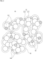
- Fig. 2 is a schematic view conceptually showing the composition of the cathode catalyst layer 31.
- the cathode catalyst layer 31 includes catalyst supporting carbon 51, an ionomer 52, and a water-repellent carbon particle 53.
- the ionomer 52 is an electrolyte polymer covering the catalyst supporting carbon 51.
- the ionomer 52 functions to transport hydrogen ions supplied from the electrolyte membrane 10 in the cathode catalyst layer 31.
- nafion perfluorocarbon sulfonic acid
- the ionomer 52 has a polymer chain structure with an ion-exchange group such as a sulfone group.
- the hydrogen ions supplied from the electrolyte membrane 10 are combined with water in the cathode catalyst layer 31 to become oxonium ions (H 3 O + ). These oxonium ions propagate through the ion-exchange group of the ionomer 52.
- the ratio of the ionomer 52 to the catalyst supporting carbon 51 is desirably set to a ratio with which the catalyst supporting carbon 51 is covered with the ionomer 52 favorably and with which oxygen gas is caused to diffuse and water is output favorably. More specifically, the ratio (ratio by weight) of the ionomer 52 to the catalyst supporting carbon 51 is desirably set equal to or greater than 30 wt% and equal to or less than 100 wt%. More desirably, the ratio (ratio by weight) of the ionomer 52 to the catalyst supporting carbon 51 is set equal to or greater than 60 wt% and equal to or less than 100 wt%. Still more desirably, the ratio (ratio by weight) of the ionomer 52 to the catalyst supporting carbon 51 is set equal to or greater than 75 wt% and equal to or less than 85 wt%.
Landscapes
- Chemical & Material Sciences (AREA)
- Chemical Kinetics & Catalysis (AREA)
- Electrochemistry (AREA)
- General Chemical & Material Sciences (AREA)
- Engineering & Computer Science (AREA)
- Manufacturing & Machinery (AREA)
- Materials Engineering (AREA)
- Life Sciences & Earth Sciences (AREA)
- Sustainable Development (AREA)
- Sustainable Energy (AREA)
- Inert Electrodes (AREA)
- Fuel Cell (AREA)
Abstract
Description
- The present invention relates to a membrane electrode assembly, a polymer electrolyte fuel cell, a method of producing catalyst ink, and a method of producing a membrane electrode assembly.
- A fuel cell conventionally known generates electric power through an electrochemical reaction between hydrogen (H2) in a fuel and oxygen (O2) in the air. Several types of fuel cell are prepared in response to electrolytes to be used. One of these types is a polymer electrolyte fuel cell that uses an ion-exchange membrane (electrolyte membrane) as an electrolyte. The polymer electrolyte fuel cell is capable of operating at ordinary temperature and capable of being reduced in size and weight, so that it is used for various purposes of use such as for automobiles, portable equipment, houses, etc.
- The polymer electrolyte fuel cell has a configuration with catalyst layers formed on both surfaces of an electrolyte membrane. During use of the polymer electrolyte fuel cell, hydrogen gas is supplied to an anode-side catalyst layer and oxygen gas is supplied to a cathode-side catalyst layer. This causes electrochemical reactions as follows at the anode-side catalyst layer and the cathode-side catalyst layer to generate electric power.
- (anode side)
H2 → 2H+ + 2e-
- (cathode side)
1/2O2 + 2H+ + 2e- → H2O
- The conventional polymer electrolyte fuel cell is disclosed in
Patent Literature 1, for example. - Patent Literature 1:
Japanese Patent Application Laid-Open No. 2020-077474 - As described above, in the polymer electrolyte fuel cell, water is generated in the cathode-side catalyst layer. This necessitates supply of oxygen gas and output of water to and from the cathode-side catalyst layer. In some cases, during these supply and output, poor performance of outputting water makes it difficult for oxygen gas to diffuse in the catalyst layer. This causes a problem of degradation of the voltage characteristics of the fuel cell.
- In this regard, in
Patent Literature 1 mentioned above, a fibrous material such as a carbon nanotube or a carbon nanofiber is provided at the cathode-side catalyst layer to improve the performance of outputting water from the catalyst layer. However, as an electrolyte membrane of the polymer electrolyte fuel cell is considerably thin, providing the fibrous material might cause damage on the electrolyte membrane. Hence, in the method ofPatent Literature 1, implementing a leak test on the electrolyte membrane is considered to be required in a manufacturing step. - The present invention has been made in view of the above-described circumstances, and is intended to provide a technique that achieves improvement of the performance of outputting water from a catalyst layer without use of a fibrous material such as that used in
Patent Literature 1. - To solve the above-described problem, a first aspect of the present invention is intended for a membrane electrode assembly comprising: an electrolyte membrane; and a cathode catalyst layer formed on one surface of the electrolyte membrane, wherein the cathode catalyst layer includes: catalyst supporting carbon with a carbon particle and a catalyst particle supported on the carbon particle; an ionomer; and a water-repellent carbon particle with a fluorine group.
- According to a second aspect of the present invention, in the membrane electrode assembly according to the first aspect, the ratio of the water-repellent carbon particle to the catalyst supporting carbon is equal to or greater than 2 wt% and equal to or less than 20 wt%.
- According to a third aspect of the present invention, in the membrane electrode assembly according to the second aspect, the ratio of the water-repellent carbon particle to the catalyst supporting carbon is equal to or greater than 5 wt% and equal to or less than 15 wt%.
- According to a fourth aspect of the present invention, in the membrane electrode assembly according to any one of the first to third aspects, the ionomer has an EW value of equal to or less than 950.
- According to a fifth aspect of the present invention, in the membrane electrode assembly according to any one of the first to fourth aspects, the ratio of the ionomer to the catalyst supporting carbon is equal to or greater than 30 wt% and equal to or less than 100 wt%.
- According to a sixth aspect of the present invention, in the membrane electrode assembly according to any one of the first to fifth aspects, the catalyst particle contains platinum.
- According to a seventh aspect of the present invention, in the membrane electrode assembly according to the sixth aspect, the ratio of the platinum to the carbon particle is equal to or greater than 38 wt% and equal to or less than 65 wt%.
- According to an eighth aspect of the present invention, in the membrane electrode assembly according to any one of the first to seventh aspects, the membrane electrode assembly is used in a polymer electrolyte fuel cell.
- A ninth aspect of the present invention is intended for a polymer electrolyte fuel cell comprising the membrane electrode assembly according to the eighth aspect.
- A tenth aspect of the present invention is intended for a method of producing catalyst ink to become a cathode catalyst layer of a membrane electrode assembly, comprising: a first step of forming a first preparation liquid by blending a carbon particle, a catalyst particle, and water; a second step of forming a second preparation liquid by adding an alcohol solution to the first preparation liquid; a third step of forming a third preparation liquid by adding a water-repellent carbon particle with a fluorine group to the second preparation liquid; and a fourth step of forming a fourth preparation liquid by adding a solution of an ionomer to the third preparation liquid.
- According to an eleventh aspect of the present invention, in the method of producing the catalyst ink according to the tenth aspect, the ratio of the alcohol solution to the catalyst ink is equal to or greater than 15 wt%.
- A twelfth aspect of the present invention is intended for a method of producing a membrane electrode assembly comprising the step of: applying catalyst ink produced by the producing method according to the tenth or eleventh aspect to one surface of an electrolyte membrane and drying the applied catalyst ink, thereby forming the cathode catalyst layer.
- According to the first to ninth aspects of the present invention, adding the water-repellent carbon particle to the cathode catalyst layer achieves improvement of the performance of outputting water from the cathode catalyst layer.
- In particular, the second aspect of the present invention achieves improvement of the performance of outputting water from the cathode catalyst layer and achieves reduction in the probability of degradation of electrical conductivity in the cathode catalyst layer caused by the influence of the fluorine group.
- In particular, the third aspect of the present invention achieves further improvement of the performance of outputting water from the cathode catalyst layer and achieves further reduction in the probability of degradation of electrical conductivity in the cathode catalyst layer caused by the influence of the fluorine group.
- In particular, according to the fourth aspect of the present invention, the number of ion-exchange groups in a polymer chain of the ionomer is increased. This allows oxonium ions to propagate favorably.
- In particular, the fifth aspect of the present invention allows the catalyst supporting carbon to be covered with the ionomer favorably. Furthermore, the presence of a void left in the cathode catalyst layer achieves favorable supply of oxygen gas and favorable output of water generated in the cathode catalyst layer.
- In particular, the seventh aspect of the present invention makes it possible to restrain the thickness of the cathode catalyst layer and to maintain a distance between particles of the platinum in such a manner as to prevent fusion between the platinum particles.
- In particular, the eighth aspect of the present invention achieves improvement of the performance of outputting water from the cathode catalyst layer, making it possible to improve the voltage characteristics of the polymer electrolyte fuel cell.
- According to the tenth to twelfth aspects of the present invention, the water-repellent carbon particle is added to the catalyst ink to become the cathode catalyst layer. This achieves improvement of the performance of outputting water from the cathode catalyst layer. Furthermore, the water-repellent carbon particle is added after addition of the alcohol solution. This allows the water-repellent carbon particle to disperse uniformly.
- In particular, the eleventh aspect of the present invention allows the water-repellent carbon particle to disperse more uniformly.
-
-
Fig. 1 is a schematic view of a cell of a polymer electrolyte fuel cell; -
Fig. 2 is a schematic view conceptually showing the composition of a cathode catalyst layer; -
Fig. 3 is a conceptual view of a water-repellent carbon particle; -
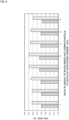
Fig. 4 is a graph showing a relationship between the quantity of the water-repellent carbon particles added to the cathode catalyst layer and the voltage characteristics of the polymer electrolyte fuel cell; -
Fig. 5 is a flowchart showing a procedure of producing catalyst ink; -
Fig. 6 is a flowchart showing a procedure of producing a membrane electrode assembly; and -
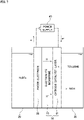
Fig. 7 shows an example of using the membrane electrode assembly in the process of hydrogenating toluene. - A preferred embodiment of the present invention will be described below by referring to the drawings.
-
Fig. 1 is a schematic view of acell 1 as one of cells of a polymer electrolyte fuel cell (PEFC) according to a preferred embodiment of the present invention. The polymer electrolyte fuel cell has a configuration with a plurality of thecells 1 shown inFig. 1 stacked in series in multiple layers. Alternatively, the polymer electrolyte fuel cell may be composed of thesingle cell 1. - As shown in
Fig. 1 , thecell 1 of the polymer electrolyte fuel cell includes anelectrolyte membrane 10, ananode catalyst layer 21, an anodegas diffusion layer 22, ananode gasket 23, ananode separator 24, acathode catalyst layer 31, a cathodegas diffusion layer 32, acathode gasket 33, and acathode separator 34. Of these layers of thecell 1, theelectrolyte membrane 10, theanode catalyst layer 21, and thecathode catalyst layer 31 form a stack corresponding to a membrane electrode assembly (MEA) 50 according to the preferred embodiment of the present invention. - The
electrolyte membrane 10 is a membrane like a thin plate having ion conductivity (ion-exchange membrane). A fluorine-based or hydrocarbon-based polymer electrolyte membrane is used as theelectrolyte membrane 10. More specifically, a polymer electrolyte membrane containing perfluorocarbon sulfonic acid is used as theelectrolyte membrane 10, for example. Theelectrolyte membrane 10 has a thickness from 5 to 30 µm, for example. - The
anode catalyst layer 21 is a layer functioning as an anode-side electrode (negative electrode) of the polymer electrolyte fuel cell. Theanode catalyst layer 21 is formed on an anode-side surface of theelectrolyte membrane 10. Theanode catalyst layer 21 contains a large number of catalyst particles. The catalyst particles are particles of a platinum alloy, for example. As an example, the platinum alloy is an alloy of at least one type of metal selected from a group including ruthenium (Ru), palladium (Pd), nickel (Ni), molybdenum (Mo), iridium (Ir), and iron (Fe), and platinum (Pt). During use of the polymer electrolyte fuel cell, hydrogen gas (H2) is supplied to theanode catalyst layer 21. Then, by the action of the catalyst particles in theanode catalyst layer 21, the hydrogen is decomposed into hydrogen ions (H+) and electrons (e-). - The anode
gas diffusion layer 22 is a layer for supplying hydrogen gas uniformly to theanode catalyst layer 21 and for causing electrons generated in theanode catalyst layer 21 to flow to theanode separator 24. The anodegas diffusion layer 22 is stacked on an outer surface of theanode catalyst layer 21. Theanode catalyst layer 21 is interposed between theelectrolyte membrane 10 and the anodegas diffusion layer 22. The anodegas diffusion layer 22 has electrical conductivity and is made of a porous material. As an example, carbon paper is used as the anodegas diffusion layer 22. - The
anode gasket 23 is a layer for preventing leakage of hydrogen gas from theanode catalyst layer 21 and from the anodegas diffusion layer 22 to their surroundings. As shown inFig. 1 , theanode gasket 23 is formed on the anode-side surface of theelectrolyte membrane 10 and surrounds theanode catalyst layer 21 and the anodegas diffusion layer 22. - The
anode separator 24 is a layer for supplying hydrogen gas to the anodegas diffusion layer 22 and for outputting electrons coming from theanode catalyst layer 21 through the anodegas diffusion layer 22 to anexternal circuit 40. Theanode separator 24 is formed on an outer surface of the anodegas diffusion layer 22 and on an outer surface of theanode gasket 23. Theanode catalyst layer 21, the anodegas diffusion layer 22, and theanode gasket 23 are interposed between theelectrolyte membrane 10 and theanode separator 24. Theanode separator 24 has electrical conductivity and is made of a material without permeability to gas. Theanode separator 24 is provided with a large number ofgrooves 241. The hydrogen gas is supplied to the anodegas diffusion layer 22 through thegrooves 241 of theanode separator 24. - The
cathode catalyst layer 31 is a layer functioning as a cathode-side electrode (positive electrode) of the polymer electrolyte fuel cell. Thecathode catalyst layer 31 is formed on a cathode-side surface of the electrolyte membrane 10 (a surface on the opposite side to the anode catalyst layer 21). Thecathode catalyst layer 31 contains a large number of carbon particles on which catalyst particles are supported. The catalyst particles are particles of platinum, for example. Alternatively, the catalyst particles may be prepared by mixing a tiny amount of ruthenium or cobalt particles into particles of platinum. During use of the polymer electrolyte fuel cell, oxygen gas (O2), hydrogen ions (H+), and electrons (e-) are supplied to thecathode catalyst layer 31. Then, by the action of the catalyst particles in thecathode catalyst layer 31, water (H2O) is generated from the oxygen gas, hydrogen ions, and electrons. - The composition of the
cathode catalyst layer 31 will be described later in more detail. - The cathode
gas diffusion layer 32 is a layer for supplying oxygen gas uniformly to thecathode catalyst layer 31 and for causing electrons to flow from thecathode separator 34 to thecathode catalyst layer 31. The cathodegas diffusion layer 32 is stacked on an outer surface of thecathode catalyst layer 31. Thecathode catalyst layer 31 is interposed between theelectrolyte membrane 10 and the cathodegas diffusion layer 32. The cathodegas diffusion layer 32 has electrical conductivity and is made of a porous material. As an example, carbon paper is used as the cathodegas diffusion layer 32. - The
cathode gasket 33 is a layer for preventing leakage of oxygen gas and water from thecathode catalyst layer 31 and from the cathodegas diffusion layer 32 to their surroundings. As shown inFig. 1 , thecathode gasket 33 is formed on the cathode-side surface of theelectrolyte membrane 10 and surrounds thecathode catalyst layer 31 and the cathodegas diffusion layer 32. - The
cathode separator 34 is a layer for supplying oxygen gas to the cathodegas diffusion layer 32 and for causing electrons supplied from theexternal circuit 40 to flow into the cathodegas diffusion layer 32. Thecathode separator 34 is formed on an outer surface of the cathodegas diffusion layer 32 and on an outer surface of thecathode gasket 33. Thecathode catalyst layer 31, the cathodegas diffusion layer 32, and thecathode gasket 33 are interposed between theelectrolyte membrane 10 and thecathode separator 34. Thecathode separator 34 has electrical conductivity and is made of a material without permeability to gas. Thecathode separator 34 is provided with a large number ofgrooves 341. The oxygen gas passes through thegrooves 341 of thecathode separator 34 and is then supplied to the cathodegas diffusion layer 32. - The
external circuit 40 is connected between theanode separator 24 and thecathode separator 34. More specifically, theexternal circuit 40 has a negative terminal electrically connected to theanode separator 24. Theexternal circuit 40 has a positive terminal electrically connected to thecathode separator 34. - During use of the polymer electrolyte fuel cell, hydrogen gas is supplied as fuel from the
anode separator 24 to theanode catalyst layer 21 through the anodegas diffusion layer 22. Then, by the action of the catalyst particles in theanode catalyst layer 21, hydrogen atoms are decomposed into hydrogen ions and electrons. The hydrogen ions propagate through theelectrolyte membrane 10 into thecathode catalyst layer 31. The electrons pass through the anodegas diffusion layer 22, theanode separator 24, theexternal circuit 40, thecathode separator 34, and the cathodegas diffusion layer 32 and then flow into thecathode catalyst layer 31. On the cathode side of thecell 1, oxygen gas is supplied from thecathode separator 34 to thecathode catalyst layer 31 through the cathodegas diffusion layer 32. Then, by the action of the catalyst particles in thecathode catalyst layer 31, water is generated from the oxygen gas, hydrogen ions, and electrons. The generated water passes through the cathodegas diffusion layer 32 and thecathode separator 34 and is then output to the outside. - The composition of the above-described
cathode catalyst layer 31 will be described next in more detail. -
Fig. 2 is a schematic view conceptually showing the composition of thecathode catalyst layer 31. As shown inFig. 2 , thecathode catalyst layer 31 includescatalyst supporting carbon 51, anionomer 52, and a water-repellent carbon particle 53. - The
catalyst supporting carbon 51 includes a large number ofcarbon particles 511 andmultiple catalyst particles 512 supported on thecarbon particles 511. Thecatalyst particles 512 are particles of platinum (Pt), for example. Alternatively, thecatalyst particles 512 may be prepared by mixing a tiny amount of ruthenium or cobalt particles into particles of platinum. - If the ratio of the platinum to the
carbon particles 511 is too small in thecatalyst supporting carbon 51, it becomes impossible to achieve sufficient catalysis. Conversely, the quantity of thecarbon particles 511 is required to be increased for achieving sufficient catalysis and this unintentionally causes increase in the thickness of thecathode catalyst layer 31. On the other hand, if the ratio of the platinum to thecarbon particles 511 is too large, distances between particles of the platinum are reduced. In this case, the platinum particles fuse with each other during electric power generation to cause a problem of reducing the performance of generating electric power. - Thus, the ratio of the platinum to the
carbon particles 511 is desirably set to a ratio with which the thickness of thecathode catalyst layer 31 is restrained and with which the distances between the platinum particles are maintained in such a manner as to prevent fusion between the platinum particles. More specifically, the ratio (ratio by weight) of the platinum to thecarbon particles 511 is desirably set equal to or greater than 38 wt% and equal to or less than 65 wt%. More desirably, the ratio (ratio by weight) of the platinum to thecarbon particles 511 is set equal to or greater than 40 wt% and equal to or less than 55 wt%. - The
ionomer 52 is an electrolyte polymer covering thecatalyst supporting carbon 51. Theionomer 52 functions to transport hydrogen ions supplied from theelectrolyte membrane 10 in thecathode catalyst layer 31. For example, nafion (perfluorocarbon sulfonic acid) is used as theionomer 52. Theionomer 52 has a polymer chain structure with an ion-exchange group such as a sulfone group. The hydrogen ions supplied from theelectrolyte membrane 10 are combined with water in thecathode catalyst layer 31 to become oxonium ions (H3O+). These oxonium ions propagate through the ion-exchange group of theionomer 52. - For favorable propagation of the oxonium ions, it is desirable to prepare a large number of ion-exchange groups in the polymer chain of the
ionomer 52. More specifically, it is desirable that an EW value indicating the dry mass of theionomer 52 per mol of ion-exchange groups (the reciprocal of the number of ion-exchange groups per unit mass of the ionomer 52) will be set equal to or less than 950. For example, the EW value is desirably set equal to or greater than 650 and equal to or less than 950. - If the ratio of the
ionomer 52 to thecatalyst supporting carbon 51 is too small, it becomes impossible to cover thecatalyst supporting carbon 51 with theionomer 52 sufficiently. This makes it difficult for oxonium ions to propagate through theionomer 52 favorably. On the other hand, if the ratio of theionomer 52 to thecatalyst supporting carbon 51 is too large, voids in thecathode catalyst layer 31 are reduced. This becomes hindrance to diffusion of oxygen gas in thecathode catalyst layer 31 or to output of water generated in thecathode catalyst layer 31. - Thus, the ratio of the
ionomer 52 to thecatalyst supporting carbon 51 is desirably set to a ratio with which thecatalyst supporting carbon 51 is covered with theionomer 52 favorably and with which oxygen gas is caused to diffuse and water is output favorably. More specifically, the ratio (ratio by weight) of theionomer 52 to thecatalyst supporting carbon 51 is desirably set equal to or greater than 30 wt% and equal to or less than 100 wt%. More desirably, the ratio (ratio by weight) of theionomer 52 to thecatalyst supporting carbon 51 is set equal to or greater than 60 wt% and equal to or less than 100 wt%. Still more desirably, the ratio (ratio by weight) of theionomer 52 to thecatalyst supporting carbon 51 is set equal to or greater than 75 wt% and equal to or less than 85 wt%. - The water-
repellent carbon particle 53 is an additive for improving the performance of outputting water from thecathode catalyst layer 31.Fig. 3 is a conceptual view of the water-repellent carbon particle 53. As shown inFig. 3 , the water-repellent carbon particle 53 has a surface provided with multiple fluorine groups (F) with water repellency. The water-repellent carbon particle 53 has a diameter of equal to or greater than 2 nm and equal to or less than 500 nm, for example. The water-repellent carbon particle 53 has a specific surface area of equal to or greater than 50 m2/g and equal to or less than 900 m2/g, for example. -
Fig. 4 is a graph showing a relationship between the quantity of the water-repellent carbon particles 53 added to thecathode catalyst layer 31 and the voltage characteristics of the polymer electrolyte fuel cell. In the graph ofFig. 4 , a horizontal axis shows the ratio (ratio by weight) of the water-repellent carbon particles 53 to thecatalyst supporting carbon 51. A vertical axis shows an output voltage obtained from the polymer electrolyte fuel cell. A voltage value shown in the graph ofFig. 4 is determined at a current density of 1.5 A/cm2. The voltage characteristics shown in the graph ofFig. 4 are determined in two cases including one case where the relative humidity of supplied gas is 20% RH and the other case where this relative humidity is 100% RH - Adding the water-
repellent carbon particle 53 to thecathode catalyst layer 31 allows water generated in thecathode catalyst layer 31 to be output efficiently by means of the water-repelling action of the fluorine groups. Thus, voids are reserved in thecathode catalyst layer 31 to allow oxygen gas to be supplied efficiently. As a result, as shown inFig. 4 , adding the water-repellent carbon particle 53 to thecathode catalyst layer 31 achieves improvement of the voltage characteristics of the polymer electrolyte fuel cell compared to the absence of addition of the water-repellent carbon particle 53. - However, if the quantity of the added water-
repellent carbon particles 53 is too large, the fluorine groups having insulating properties exert influence to increase an electrical resistance in thecathode catalyst layer 31. Hence, like in a case shown inFig. 4 where the ratio by weight of the water-repellent carbon particles 53 to thecatalyst supporting carbon 51 is 25 wt%, this conversely degrades the voltage characteristics of the polymer electrolyte fuel cell. - Thus, it is desirable that the water-
repellent carbon particles 53 will be added to a quantity with which the performance of outputting water from thecathode catalyst layer 31 is improved and with which the probability of degradation of electrical conductivity in thecathode catalyst layer 31 caused by the influence of the fluorine groups is reduced. More specifically, the ratio (ratio by weight) of the water-repellent carbon particles 53 to thecatalyst supporting carbon 51 is desirably set equal to or greater than 2 wt% and equal to or less than 20 wt%. More desirably, the ratio (ratio by weight) of the water-repellent carbon particles 53 to thecatalyst supporting carbon 51 is set equal to or greater than 5 wt% and equal to or less than 15 wt%. For example, the ratio (ratio by weight) of the water-repellent carbon particles 53 to thecatalyst supporting carbon 51 is preferably set to 10 wt%. - As described above, in the
cathode catalyst layer 31, hydrogen ions are combined with water to propagate as oxonium ions. Thus, for increasing the performance of the cell, moisture of a certain degree is desirably retained uniformly in thecathode catalyst layer 31. However, too much moisture hinders diffusion of oxygen gas in thecathode catalyst layer 31. For this reason, it is desirable to optimize a moisture content to be retained in thecathode catalyst layer 31. - In this regard, reducing the above-described EW value of the
ionomer 52 contributes to increasing a moisture content in thecathode catalyst layer 31. On the other hand, adding the water-repellent carbon particles 53 contributes to reducing a moisture content in thecathode catalyst layer 31. Thus, by setting the EW value of theionomer 52 equal to or less than 950 and by adding the water-repellent carbon particles 53 as described above, it becomes possible to keep a moisture content retained in thecathode catalyst layer 31 within an appropriate range. This achieves further improvement of the voltage characteristics of the polymer electrolyte fuel cell. - The
cathode catalyst layer 31 is formed by applying catalyst ink in paste form on a surface of theelectrolyte membrane 10. The following describes a method of producing the catalyst ink to become thecathode catalyst layer 31. -
Fig. 5 is a flowchart showing a procedure of producing the catalyst ink. As shown inFig, 5 , for producing the catalyst ink, thecarbon particles 511, thecatalyst particles 512, and water are first blended to form a first preparation liquid (first step S1). In the first step S1, the water is added to prevent thecarbon particles 511 from catching fire. - Next, an alcohol solution is added to the first preparation liquid to form a second preparation liquid (second step S2). The alcohol solution is methanol, ethanol, 1-propanol, or 2-propanol, for example.
- Next, the water-
repellent carbon particles 53 with fluorine groups are added to the second preparation liquid to form a third preparation liquid (third step S3). In the third step S3, the water-repellent carbon particles 53 disperse in the alcohol solution added in the second step S2. Adding the water-repellent carbon particles 53 in the above-described first step S1 makes it likely that the water-repellent carbon particles 53 will form lumps as a result of being prevented from dispersing in the first preparation liquid by the water-repelling action of the fluorine groups. By contrast, according to the present preferred embodiment, the alcohol solution having a small angle of contact (having high compatibility with the water-repellent carbon particles 53) is added in advance in the second step S2, and then the water-repellent carbon particles 53 are added in the third step S3. This allows the water-repellent carbon particles 53 to disperse uniformly in the third preparation liquid. - Next, an ionomer solution is added to the third preparation liquid to form a fourth preparation liquid (fourth step S4). The ionomer solution is a solution prepared by dissolving the
ionomer 52 in water and alcohol. The ionomer solution has a high proportion of water, so that it is added after the water-repellent carbon particles 53 are added and disperse in the third step S3. - Next, dispersing process is performed further on the fourth preparation liquid (fifth step S5). In the fifth step, the fourth preparation liquid is agitated, for example. This causes the water-
repellent carbon particles 53 to disperse more uniformly in the fourth preparation liquid. As a result, the catalyst ink is generated. The ratio (ratio by weight) of the alcohol solution to the catalyst ink finally generated is desirably set equal to or greater than 15 wt%. This allows the water-repellent carbon particles 53 to disperse with still higher performance in the catalyst ink. - A method of producing the
membrane electrode assembly 50 using the above-described catalyst ink will be described next. -
Fig. 6 is a flowchart showing a procedure of producing themembrane electrode assembly 50. As shown inFig. 6 , for producing themembrane electrode assembly 50, the catalyst ink for cathode produced by the above-described procedure is applied to one of the surfaces of the electrolyte membrane 10 (sixth step S6). Then, the applied catalyst ink is dried (seventh step S7). By doing so, thecathode catalyst layer 31 is formed on the one surface of theelectrolyte membrane 10. - Furthermore, catalyst ink for anode is applied to the other surface of the electrolyte membrane 10 (eighth step S8). Then, the applied catalyst ink is dried (ninth step S9). By doing so, the
anode catalyst layer 21 is formed on the other surface of theelectrolyte membrane 10. As a result, themembrane electrode assembly 50 composed of theelectrolyte membrane 10, theanode catalyst layer 21, and thecathode catalyst layer 31 is obtained. - Order of implementation may be reversed between formation of the
cathode catalyst layer 31 including the sixth step S6 and the seventh step S7 and formation of theanode catalyst layer 21 including the eighth step S8 and the ninth step S9. - The preferred embodiment described above is intended for the
membrane electrode assembly 50 used in the polymer electrolyte fuel cell. However, the membrane electrode assembly of the present invention may be used for purpose other than the polymer electrolyte fuel cell. - According to one exemplary technique, an organic hydride (methylcyclohexane, for example) prepared by hydrogenating an aromatic compound such as toluene is used as a carrier for transporting hydrogen.
Fig. 7 shows an example of a device of generating the organic hydride according to this technique. The device ofFig. 7 uses themembrane electrode assembly 50 including theelectrolyte membrane 10 and thecathode catalyst layer 31 formed on one surface of theelectrolyte membrane 10. The composition of thecathode catalyst layer 31 is the same as that in the above-described case of the polymer electrolyte fuel cell. - Sulfuric acid is stored in a
reservoir 26 on the anode side. Toluene is stored in areservoir 36 on the cathode side. By applying a voltage between thecathode catalyst layer 31 and ananode electrode 25 and supplying electrons (e-) to thecathode catalyst layer 31, the following electroreduction reaction is caused in thecathode catalyst layer 31. By doing so, methylcyclohexane (MCH) as an organic hydride can be obtained.
C7H8 + 6H+ + 6e- → C7H14
- As described above, the water-
repellent carbon particles 53 with fluorine groups may be added to thecathode catalyst layer 31 of themembrane electrode assembly 50 used in the process of hydrogenating toluene. -
- 1
- Cell of polymer electrolyte fuel cell
- 10
- Electrolyte membrane
- 21
- Anode catalyst layer
- 22
- Anode gas diffusion layer
- 23
- Anode gasket
- 24
- Anode separator
- 25
- Anode electrode
- 31
- Cathode catalyst layer
- 32
- Cathode gas diffusion layer
- 33
- Cathode gasket
- 34
- Cathode separator
- 40
- External circuit
- 50
- Membrane electrode assembly
- 51
- Catalyst supporting carbon
- 52
- Ionomer
- 53
- Water-repellent carbon particle
- 241
- Groove of anode separator
- 341
- Groove of cathode separator
- 511
- Carbon particle
- 512
- Catalyst particle
Claims (12)
- A membrane electrode assembly (50) comprising:an electrolyte membrane (10); anda cathode catalyst layer (31) formed on one surface of said electrolyte membrane (10), whereinsaid cathode catalyst layer (31) includes:catalyst supporting carbon (51) with a carbon particle (511) and a catalyst particle (512) supported on said carbon particle (511);an ionomer (52); anda water-repellent carbon particle (53) with a fluorine group.
- The membrane electrode assembly (50) according to claim 1, wherein
the ratio of said water-repellent carbon particle (53) to said catalyst supporting carbon (51) is equal to or greater than 2 wt% and equal to or less than 20 wt%. - The membrane electrode assembly (50) according to claim 2, wherein
the ratio of said water-repellent carbon particle (53) to said catalyst supporting carbon (51) is equal to or greater than 5 wt% and equal to or less than 15 wt%. - The membrane electrode assembly (50) according to any one of claims 1 to 3, wherein
said ionomer (52) has an EW value of equal to or less than 950. - The membrane electrode assembly (50) according to any one of claims 1 to 4, wherein
the ratio of said ionomer (52) to said catalyst supporting carbon (51) is equal to or greater than 30 wt% and equal to or less than 100 wt%. - The membrane electrode assembly (50) according to any one of claims 1 to 5, wherein
said catalyst particle (512) contains platinum. - The membrane electrode assembly (50) according to claim 6, wherein
the ratio of said platinum to said carbon particle (511) is equal to or greater than 38 wt% and equal to or less than 65 wt%. - The membrane electrode assembly (50) according to any one of claims 1 to 7, wherein
the membrane electrode assembly (50) is used in a polymer electrolyte fuel cell. - A polymer electrolyte fuel cell comprising the membrane electrode assembly (50) according to claim 8.
- A method of producing catalyst ink to become a cathode catalyst layer (31) of a membrane electrode assembly (50), comprising:a first step (S1) of forming a first preparation liquid by blending a carbon particle (511), a catalyst particle (512), and water;a second step (S2) of forming a second preparation liquid by adding an alcohol solution to said first preparation liquid;a third step (S3) of forming a third preparation liquid by adding a water-repellent carbon particle (53) with a fluorine group to said second preparation liquid; anda fourth step (S4) of forming a fourth preparation liquid by adding a solution of an ionomer (52) to said third preparation liquid.
- The method of producing the catalyst ink according to claim 10, wherein the ratio of said alcohol solution to said catalyst ink is equal to or greater than 15 wt%.
- A method of producing a membrane electrode assembly (50) comprising the step of:
applying catalyst ink produced by the producing method according to claim 10 or 11 to one surface of an electrolyte membrane (10) and drying the applied catalyst ink, thereby forming said cathode catalyst layer (31).
Applications Claiming Priority (1)
| Application Number | Priority Date | Filing Date | Title |
|---|---|---|---|
| JP2021147417A JP7401493B2 (en) | 2021-09-10 | 2021-09-10 | Method for manufacturing catalyst ink and method for manufacturing membrane electrode assembly |
Publications (2)
| Publication Number | Publication Date |
|---|---|
| EP4148842A1 true EP4148842A1 (en) | 2023-03-15 |
| EP4148842B1 EP4148842B1 (en) | 2025-01-29 |
Family
ID=82163505
Family Applications (1)
| Application Number | Title | Priority Date | Filing Date |
|---|---|---|---|
| EP22180056.8A Active EP4148842B1 (en) | 2021-09-10 | 2022-06-21 | Membrane electrode assembly, polymer electrolyte fuel cell, method of producing catalyst ink, and method of producing membrane electrode assembly |
Country Status (4)
| Country | Link |
|---|---|
| EP (1) | EP4148842B1 (en) |
| JP (1) | JP7401493B2 (en) |
| KR (1) | KR102765463B1 (en) |
| CN (1) | CN115799526B (en) |
Cited By (1)
| Publication number | Priority date | Publication date | Assignee | Title |
|---|---|---|---|---|
| CN115786929A (en) * | 2021-09-13 | 2023-03-14 | 株式会社斯库林集团 | Membrane electrode assembly, method for producing same, hydrogen production apparatus, and method for producing ink |
Families Citing this family (1)
| Publication number | Priority date | Publication date | Assignee | Title |
|---|---|---|---|---|
| WO2025146930A1 (en) * | 2024-01-02 | 2025-07-10 | 코오롱인더스트리 주식회사 | Catalyst layer for fuel cell, membrane-electrode assembly, and fuel cell comprising same |
Citations (5)
| Publication number | Priority date | Publication date | Assignee | Title |
|---|---|---|---|---|
| US20050214631A1 (en) * | 2004-03-26 | 2005-09-29 | Takayuki Hirashige | Fuel cell and membrane electrode assembly |
| JP2009218006A (en) * | 2008-03-07 | 2009-09-24 | Nissan Motor Co Ltd | Method of manufacturing electrolyte membrane-electrode assembly |
| EP2750226A1 (en) * | 2011-08-25 | 2014-07-02 | Nissan Motor Co., Ltd. | Electrode catalyst layer for fuel cells, electrode for fuel cells, membrane electrode assembly for fuel cells, and fuel cell |
| US20180261866A1 (en) * | 2015-09-09 | 2018-09-13 | Nissan Motor Co., Ltd. | Fuel cell electrode catalyst layer and manufacturing method therefor, and membrane electrode assembly, fuel cell, and vehicle using catalyst layer |
| JP2020077474A (en) | 2018-11-05 | 2020-05-21 | 凸版印刷株式会社 | Membrane electrode assembly and polymer electrolyte fuel cell |
Family Cites Families (5)
| Publication number | Priority date | Publication date | Assignee | Title |
|---|---|---|---|---|
| JP5345870B2 (en) * | 2009-02-18 | 2013-11-20 | 本田技研工業株式会社 | Method for producing membrane-electrode assembly |
| JP7128634B2 (en) * | 2017-03-10 | 2022-08-31 | 株式会社豊田中央研究所 | Ionoma-coated catalyst, manufacturing method thereof, and catalyst ink |
| JP7190171B2 (en) * | 2018-04-25 | 2022-12-15 | ステラケミファ株式会社 | FUEL CELL CATALYST, METHOD FOR MANUFACTURING THE SAME, MEMBRANE ELECTRODE ASSEMBLY FOR FUEL CELL, AND FUEL CELL INCLUDING THE SAME |
| KR102455396B1 (en) * | 2018-05-30 | 2022-10-17 | 주식회사 엘지화학 | Catalyst ink for forming electrode catalyst layer of fuel cell and manufacturing method thereof |
| WO2020022191A1 (en) * | 2018-07-25 | 2020-01-30 | パナソニックIpマネジメント株式会社 | Cathode catalyst layer of fuel cell, and fuel cell |
-
2021
- 2021-09-10 JP JP2021147417A patent/JP7401493B2/en active Active
-
2022
- 2022-06-21 EP EP22180056.8A patent/EP4148842B1/en active Active
- 2022-06-28 KR KR1020220078766A patent/KR102765463B1/en active Active
- 2022-07-11 CN CN202210853667.0A patent/CN115799526B/en active Active
Patent Citations (5)
| Publication number | Priority date | Publication date | Assignee | Title |
|---|---|---|---|---|
| US20050214631A1 (en) * | 2004-03-26 | 2005-09-29 | Takayuki Hirashige | Fuel cell and membrane electrode assembly |
| JP2009218006A (en) * | 2008-03-07 | 2009-09-24 | Nissan Motor Co Ltd | Method of manufacturing electrolyte membrane-electrode assembly |
| EP2750226A1 (en) * | 2011-08-25 | 2014-07-02 | Nissan Motor Co., Ltd. | Electrode catalyst layer for fuel cells, electrode for fuel cells, membrane electrode assembly for fuel cells, and fuel cell |
| US20180261866A1 (en) * | 2015-09-09 | 2018-09-13 | Nissan Motor Co., Ltd. | Fuel cell electrode catalyst layer and manufacturing method therefor, and membrane electrode assembly, fuel cell, and vehicle using catalyst layer |
| JP2020077474A (en) | 2018-11-05 | 2020-05-21 | 凸版印刷株式会社 | Membrane electrode assembly and polymer electrolyte fuel cell |
Cited By (2)
| Publication number | Priority date | Publication date | Assignee | Title |
|---|---|---|---|---|
| CN115786929A (en) * | 2021-09-13 | 2023-03-14 | 株式会社斯库林集团 | Membrane electrode assembly, method for producing same, hydrogen production apparatus, and method for producing ink |
| CN115786929B (en) * | 2021-09-13 | 2025-04-22 | 株式会社斯库林集团 | Membrane electrode assembly and manufacturing method thereof, hydrogen manufacturing device, and ink manufacturing method |
Also Published As
| Publication number | Publication date |
|---|---|
| KR102765463B1 (en) | 2025-02-12 |
| KR20230038084A (en) | 2023-03-17 |
| CN115799526B (en) | 2024-08-09 |
| EP4148842B1 (en) | 2025-01-29 |
| CN115799526A (en) | 2023-03-14 |
| JP7401493B2 (en) | 2023-12-19 |
| JP2023040454A (en) | 2023-03-23 |
Similar Documents
| Publication | Publication Date | Title |
|---|---|---|
| US6847518B2 (en) | Membrane electrode assembly for polymer electrolyte fuel cell | |
| US9537156B2 (en) | Method for making membrane-electrode assembly for fuel cell and method for making fuel cell system comprising the same | |
| US9346673B2 (en) | Electrode for fuel cell, membrane-electrode assembly for fuel cell comprising the same, fuel cell system comprising the same, and method for preparing the electrode | |
| EP4177380B1 (en) | Membrane electrode assembly, hydrogen producing device, method of producing catalyst ink, and method of producing membrane electrode assembly | |
| KR102288596B1 (en) | Catalyst electrode for fuel cell, manufacturing method thereof and a fuel cell comprising the catalyst electrode for fuel cell | |
| KR20060117474A (en) | Electrode base material for fuel cell, manufacturing method thereof and membrane-electrode assembly comprising same | |
| EP4148842B1 (en) | Membrane electrode assembly, polymer electrolyte fuel cell, method of producing catalyst ink, and method of producing membrane electrode assembly | |
| EP1721355A1 (en) | Membrane electrode unit | |
| US7842422B2 (en) | Membrane-electrode assembly for fuel cell and fuel cell comprising the same | |
| JP5022707B2 (en) | Solid polymer electrolyte fuel cell | |
| JP2001185162A (en) | Fuel cell and its manufacturing method | |
| KR100570769B1 (en) | Fuel cell electrode and fuel cell comprising same | |
| KR20170069590A (en) | Membrane electrode assembly and fuel cell comprising the same | |
| KR102090860B1 (en) | Polymer electrolyte membrane, membrane electrode assembly comprising the same and fuel cell comprising the membrane electrode assembly | |
| KR20170004747A (en) | Membrane electrode assembly, fuel cell comprising the membrane electrode assembly and battery module having the fuel cell | |
| US20240318329A1 (en) | Electrode structure and water electrolyzer | |
| KR20150138103A (en) | Electrode for fuel cell, membrane electrode assembly comprising the same and fuel cell comprising the membrane electrode assembly | |
| KR100570768B1 (en) | Fuel cell electrode and fuel cell comprising same | |
| JP2010238415A (en) | Catalyst paste preparation method | |
| JP2005235461A (en) | Polymer electrolyte membrane / electrode assembly | |
| JP2024043895A (en) | Catalyst ink, catalyst ink manufacturing method, membrane electrode assembly manufacturing method | |
| JP2023176353A (en) | electrode catalyst layer | |
| JP2024135262A (en) | Electrode structure and water electrolysis device | |
| CN114583192A (en) | Electrode-forming composition, electrode, method for producing electrode, membrane-electrode assembly, and fuel cell | |
| KR20230082759A (en) | Composition for fuel cell electrode and manufacturing method of the same |
Legal Events
| Date | Code | Title | Description |
|---|---|---|---|
| PUAI | Public reference made under article 153(3) epc to a published international application that has entered the european phase |
Free format text: ORIGINAL CODE: 0009012 |
|
| STAA | Information on the status of an ep patent application or granted ep patent |
Free format text: STATUS: THE APPLICATION HAS BEEN PUBLISHED |
|
| AK | Designated contracting states |
Kind code of ref document: A1 Designated state(s): AL AT BE BG CH CY CZ DE DK EE ES FI FR GB GR HR HU IE IS IT LI LT LU LV MC MK MT NL NO PL PT RO RS SE SI SK SM TR |
|
| STAA | Information on the status of an ep patent application or granted ep patent |
Free format text: STATUS: REQUEST FOR EXAMINATION WAS MADE |
|
| 17P | Request for examination filed |
Effective date: 20230906 |
|
| RBV | Designated contracting states (corrected) |
Designated state(s): AL AT BE BG CH CY CZ DE DK EE ES FI FR GB GR HR HU IE IS IT LI LT LU LV MC MK MT NL NO PL PT RO RS SE SI SK SM TR |
|
| STAA | Information on the status of an ep patent application or granted ep patent |
Free format text: STATUS: EXAMINATION IS IN PROGRESS |
|
| 17Q | First examination report despatched |
Effective date: 20240222 |
|
| GRAP | Despatch of communication of intention to grant a patent |
Free format text: ORIGINAL CODE: EPIDOSNIGR1 |
|
| STAA | Information on the status of an ep patent application or granted ep patent |
Free format text: STATUS: GRANT OF PATENT IS INTENDED |
|
| INTG | Intention to grant announced |
Effective date: 20240904 |
|
| GRAS | Grant fee paid |
Free format text: ORIGINAL CODE: EPIDOSNIGR3 |
|
| GRAA | (expected) grant |
Free format text: ORIGINAL CODE: 0009210 |
|
| STAA | Information on the status of an ep patent application or granted ep patent |
Free format text: STATUS: THE PATENT HAS BEEN GRANTED |
|
| P01 | Opt-out of the competence of the unified patent court (upc) registered |
Free format text: CASE NUMBER: APP_63725/2024 Effective date: 20241202 |
|
| AK | Designated contracting states |
Kind code of ref document: B1 Designated state(s): AL AT BE BG CH CY CZ DE DK EE ES FI FR GB GR HR HU IE IS IT LI LT LU LV MC MK MT NL NO PL PT RO RS SE SI SK SM TR |
|
| REG | Reference to a national code |
Ref country code: GB Ref legal event code: FG4D |
|
| REG | Reference to a national code |
Ref country code: CH Ref legal event code: EP |
|
| REG | Reference to a national code |
Ref country code: DE Ref legal event code: R096 Ref document number: 602022009991 Country of ref document: DE |
|
| REG | Reference to a national code |
Ref country code: IE Ref legal event code: FG4D |
|
| REG | Reference to a national code |
Ref country code: NL Ref legal event code: MP Effective date: 20250129 |
|
| PG25 | Lapsed in a contracting state [announced via postgrant information from national office to epo] |
Ref country code: NL Free format text: LAPSE BECAUSE OF FAILURE TO SUBMIT A TRANSLATION OF THE DESCRIPTION OR TO PAY THE FEE WITHIN THE PRESCRIBED TIME-LIMIT Effective date: 20250129 |
|
| PG25 | Lapsed in a contracting state [announced via postgrant information from national office to epo] |
Ref country code: RS Free format text: LAPSE BECAUSE OF FAILURE TO SUBMIT A TRANSLATION OF THE DESCRIPTION OR TO PAY THE FEE WITHIN THE PRESCRIBED TIME-LIMIT Effective date: 20250429 |
|
| PG25 | Lapsed in a contracting state [announced via postgrant information from national office to epo] |
Ref country code: FI Free format text: LAPSE BECAUSE OF FAILURE TO SUBMIT A TRANSLATION OF THE DESCRIPTION OR TO PAY THE FEE WITHIN THE PRESCRIBED TIME-LIMIT Effective date: 20250129 |
|
| PG25 | Lapsed in a contracting state [announced via postgrant information from national office to epo] |
Ref country code: PL Free format text: LAPSE BECAUSE OF FAILURE TO SUBMIT A TRANSLATION OF THE DESCRIPTION OR TO PAY THE FEE WITHIN THE PRESCRIBED TIME-LIMIT Effective date: 20250129 |
|
| PGFP | Annual fee paid to national office [announced via postgrant information from national office to epo] |
Ref country code: DE Payment date: 20250626 Year of fee payment: 4 |
|
| PG25 | Lapsed in a contracting state [announced via postgrant information from national office to epo] |
Ref country code: ES Free format text: LAPSE BECAUSE OF FAILURE TO SUBMIT A TRANSLATION OF THE DESCRIPTION OR TO PAY THE FEE WITHIN THE PRESCRIBED TIME-LIMIT Effective date: 20250129 |
|
| REG | Reference to a national code |
Ref country code: LT Ref legal event code: MG9D |
|
| PG25 | Lapsed in a contracting state [announced via postgrant information from national office to epo] |
Ref country code: NO Free format text: LAPSE BECAUSE OF FAILURE TO SUBMIT A TRANSLATION OF THE DESCRIPTION OR TO PAY THE FEE WITHIN THE PRESCRIBED TIME-LIMIT Effective date: 20250429 Ref country code: IS Free format text: LAPSE BECAUSE OF FAILURE TO SUBMIT A TRANSLATION OF THE DESCRIPTION OR TO PAY THE FEE WITHIN THE PRESCRIBED TIME-LIMIT Effective date: 20250529 |
|
| REG | Reference to a national code |
Ref country code: AT Ref legal event code: MK05 Ref document number: 1764388 Country of ref document: AT Kind code of ref document: T Effective date: 20250129 |
|
| PG25 | Lapsed in a contracting state [announced via postgrant information from national office to epo] |
Ref country code: HR Free format text: LAPSE BECAUSE OF FAILURE TO SUBMIT A TRANSLATION OF THE DESCRIPTION OR TO PAY THE FEE WITHIN THE PRESCRIBED TIME-LIMIT Effective date: 20250129 |
|
| PG25 | Lapsed in a contracting state [announced via postgrant information from national office to epo] |
Ref country code: LV Free format text: LAPSE BECAUSE OF FAILURE TO SUBMIT A TRANSLATION OF THE DESCRIPTION OR TO PAY THE FEE WITHIN THE PRESCRIBED TIME-LIMIT Effective date: 20250129 Ref country code: PT Free format text: LAPSE BECAUSE OF FAILURE TO SUBMIT A TRANSLATION OF THE DESCRIPTION OR TO PAY THE FEE WITHIN THE PRESCRIBED TIME-LIMIT Effective date: 20250529 |
|
| PG25 | Lapsed in a contracting state [announced via postgrant information from national office to epo] |
Ref country code: BG Free format text: LAPSE BECAUSE OF FAILURE TO SUBMIT A TRANSLATION OF THE DESCRIPTION OR TO PAY THE FEE WITHIN THE PRESCRIBED TIME-LIMIT Effective date: 20250129 Ref country code: GR Free format text: LAPSE BECAUSE OF FAILURE TO SUBMIT A TRANSLATION OF THE DESCRIPTION OR TO PAY THE FEE WITHIN THE PRESCRIBED TIME-LIMIT Effective date: 20250430 |
|
| PG25 | Lapsed in a contracting state [announced via postgrant information from national office to epo] |
Ref country code: AT Free format text: LAPSE BECAUSE OF FAILURE TO SUBMIT A TRANSLATION OF THE DESCRIPTION OR TO PAY THE FEE WITHIN THE PRESCRIBED TIME-LIMIT Effective date: 20250129 |
|
| PG25 | Lapsed in a contracting state [announced via postgrant information from national office to epo] |
Ref country code: SE Free format text: LAPSE BECAUSE OF FAILURE TO SUBMIT A TRANSLATION OF THE DESCRIPTION OR TO PAY THE FEE WITHIN THE PRESCRIBED TIME-LIMIT Effective date: 20250129 |
|
| PG25 | Lapsed in a contracting state [announced via postgrant information from national office to epo] |
Ref country code: SM Free format text: LAPSE BECAUSE OF FAILURE TO SUBMIT A TRANSLATION OF THE DESCRIPTION OR TO PAY THE FEE WITHIN THE PRESCRIBED TIME-LIMIT Effective date: 20250129 |
|
| PG25 | Lapsed in a contracting state [announced via postgrant information from national office to epo] |
Ref country code: DK Free format text: LAPSE BECAUSE OF FAILURE TO SUBMIT A TRANSLATION OF THE DESCRIPTION OR TO PAY THE FEE WITHIN THE PRESCRIBED TIME-LIMIT Effective date: 20250129 |
|
| PG25 | Lapsed in a contracting state [announced via postgrant information from national office to epo] |
Ref country code: IT Free format text: LAPSE BECAUSE OF FAILURE TO SUBMIT A TRANSLATION OF THE DESCRIPTION OR TO PAY THE FEE WITHIN THE PRESCRIBED TIME-LIMIT Effective date: 20250129 |
|
| PG25 | Lapsed in a contracting state [announced via postgrant information from national office to epo] |
Ref country code: CZ Free format text: LAPSE BECAUSE OF FAILURE TO SUBMIT A TRANSLATION OF THE DESCRIPTION OR TO PAY THE FEE WITHIN THE PRESCRIBED TIME-LIMIT Effective date: 20250129 Ref country code: EE Free format text: LAPSE BECAUSE OF FAILURE TO SUBMIT A TRANSLATION OF THE DESCRIPTION OR TO PAY THE FEE WITHIN THE PRESCRIBED TIME-LIMIT Effective date: 20250129 |
|
| PG25 | Lapsed in a contracting state [announced via postgrant information from national office to epo] |
Ref country code: RO Free format text: LAPSE BECAUSE OF FAILURE TO SUBMIT A TRANSLATION OF THE DESCRIPTION OR TO PAY THE FEE WITHIN THE PRESCRIBED TIME-LIMIT Effective date: 20250129 |
|
| PG25 | Lapsed in a contracting state [announced via postgrant information from national office to epo] |
Ref country code: SK Free format text: LAPSE BECAUSE OF FAILURE TO SUBMIT A TRANSLATION OF THE DESCRIPTION OR TO PAY THE FEE WITHIN THE PRESCRIBED TIME-LIMIT Effective date: 20250129 |
|
| REG | Reference to a national code |
Ref country code: DE Ref legal event code: R097 Ref document number: 602022009991 Country of ref document: DE |
|
| PLBE | No opposition filed within time limit |
Free format text: ORIGINAL CODE: 0009261 |
|
| STAA | Information on the status of an ep patent application or granted ep patent |
Free format text: STATUS: NO OPPOSITION FILED WITHIN TIME LIMIT |
|
| REG | Reference to a national code |
Ref country code: CH Ref legal event code: L10 Free format text: ST27 STATUS EVENT CODE: U-0-0-L10-L00 (AS PROVIDED BY THE NATIONAL OFFICE) Effective date: 20251210 |
|
| 26N | No opposition filed |
Effective date: 20251030 |
|
| REG | Reference to a national code |
Ref country code: CH Ref legal event code: H13 Free format text: ST27 STATUS EVENT CODE: U-0-0-H10-H13 (AS PROVIDED BY THE NATIONAL OFFICE) Effective date: 20260127 |
|
| PG25 | Lapsed in a contracting state [announced via postgrant information from national office to epo] |
Ref country code: MC Free format text: LAPSE BECAUSE OF FAILURE TO SUBMIT A TRANSLATION OF THE DESCRIPTION OR TO PAY THE FEE WITHIN THE PRESCRIBED TIME-LIMIT Effective date: 20250129 |
|
| PG25 | Lapsed in a contracting state [announced via postgrant information from national office to epo] |
Ref country code: LU Free format text: LAPSE BECAUSE OF NON-PAYMENT OF DUE FEES Effective date: 20250621 |
|
| REG | Reference to a national code |
Ref country code: BE Ref legal event code: MM Effective date: 20250630 |
|
| PG25 | Lapsed in a contracting state [announced via postgrant information from national office to epo] |
Ref country code: IE Free format text: LAPSE BECAUSE OF NON-PAYMENT OF DUE FEES Effective date: 20250621 |
|
| PG25 | Lapsed in a contracting state [announced via postgrant information from national office to epo] |
Ref country code: BE Free format text: LAPSE BECAUSE OF NON-PAYMENT OF DUE FEES Effective date: 20250630 |
|
| PG25 | Lapsed in a contracting state [announced via postgrant information from national office to epo] |
Ref country code: FR Free format text: LAPSE BECAUSE OF NON-PAYMENT OF DUE FEES Effective date: 20250630 |
|
| PG25 | Lapsed in a contracting state [announced via postgrant information from national office to epo] |
Ref country code: CH Free format text: LAPSE BECAUSE OF NON-PAYMENT OF DUE FEES Effective date: 20250630 |