EP4148756A1 - Electricity storage device and method for manufacturing electricity storage device - Google Patents
Electricity storage device and method for manufacturing electricity storage device Download PDFInfo
- Publication number
- EP4148756A1 EP4148756A1 EP21800848.0A EP21800848A EP4148756A1 EP 4148756 A1 EP4148756 A1 EP 4148756A1 EP 21800848 A EP21800848 A EP 21800848A EP 4148756 A1 EP4148756 A1 EP 4148756A1
- Authority
- EP
- European Patent Office
- Prior art keywords
- external terminal
- bus bar
- welded portion
- metal layer
- energy storage
- Prior art date
- Legal status (The legal status is an assumption and is not a legal conclusion. Google has not performed a legal analysis and makes no representation as to the accuracy of the status listed.)
- Pending
Links
Images




Classifications
-
- H—ELECTRICITY
- H01—ELECTRIC ELEMENTS
- H01M—PROCESSES OR MEANS, e.g. BATTERIES, FOR THE DIRECT CONVERSION OF CHEMICAL ENERGY INTO ELECTRICAL ENERGY
- H01M50/00—Constructional details or processes of manufacture of the non-active parts of electrochemical cells other than fuel cells, e.g. hybrid cells
- H01M50/50—Current conducting connections for cells or batteries
- H01M50/502—Interconnectors for connecting terminals of adjacent batteries; Interconnectors for connecting cells outside a battery casing
- H01M50/514—Methods for interconnecting adjacent batteries or cells
- H01M50/516—Methods for interconnecting adjacent batteries or cells by welding, soldering or brazing
-
- H—ELECTRICITY
- H01—ELECTRIC ELEMENTS
- H01G—CAPACITORS; CAPACITORS, RECTIFIERS, DETECTORS, SWITCHING DEVICES, LIGHT-SENSITIVE OR TEMPERATURE-SENSITIVE DEVICES OF THE ELECTROLYTIC TYPE
- H01G11/00—Hybrid capacitors, i.e. capacitors having different positive and negative electrodes; Electric double-layer [EDL] capacitors; Processes for the manufacture thereof or of parts thereof
- H01G11/10—Multiple hybrid or EDL capacitors, e.g. arrays or modules
-
- H—ELECTRICITY
- H01—ELECTRIC ELEMENTS
- H01G—CAPACITORS; CAPACITORS, RECTIFIERS, DETECTORS, SWITCHING DEVICES, LIGHT-SENSITIVE OR TEMPERATURE-SENSITIVE DEVICES OF THE ELECTROLYTIC TYPE
- H01G11/00—Hybrid capacitors, i.e. capacitors having different positive and negative electrodes; Electric double-layer [EDL] capacitors; Processes for the manufacture thereof or of parts thereof
- H01G11/74—Terminals, e.g. extensions of current collectors
- H01G11/76—Terminals, e.g. extensions of current collectors specially adapted for integration in multiple or stacked hybrid or EDL capacitors
-
- H—ELECTRICITY
- H01—ELECTRIC ELEMENTS
- H01G—CAPACITORS; CAPACITORS, RECTIFIERS, DETECTORS, SWITCHING DEVICES, LIGHT-SENSITIVE OR TEMPERATURE-SENSITIVE DEVICES OF THE ELECTROLYTIC TYPE
- H01G11/00—Hybrid capacitors, i.e. capacitors having different positive and negative electrodes; Electric double-layer [EDL] capacitors; Processes for the manufacture thereof or of parts thereof
- H01G11/78—Cases; Housings; Encapsulations; Mountings
- H01G11/82—Fixing or assembling a capacitive element in a housing, e.g. mounting electrodes, current collectors or terminals in containers or encapsulations
-
- H—ELECTRICITY
- H01—ELECTRIC ELEMENTS
- H01M—PROCESSES OR MEANS, e.g. BATTERIES, FOR THE DIRECT CONVERSION OF CHEMICAL ENERGY INTO ELECTRICAL ENERGY
- H01M10/00—Secondary cells; Manufacture thereof
- H01M10/05—Accumulators with non-aqueous electrolyte
- H01M10/052—Li-accumulators
- H01M10/0525—Rocking-chair batteries, i.e. batteries with lithium insertion or intercalation in both electrodes; Lithium-ion batteries
-
- H—ELECTRICITY
- H01—ELECTRIC ELEMENTS
- H01M—PROCESSES OR MEANS, e.g. BATTERIES, FOR THE DIRECT CONVERSION OF CHEMICAL ENERGY INTO ELECTRICAL ENERGY
- H01M50/00—Constructional details or processes of manufacture of the non-active parts of electrochemical cells other than fuel cells, e.g. hybrid cells
- H01M50/10—Primary casings; Jackets or wrappings
- H01M50/102—Primary casings; Jackets or wrappings characterised by their shape or physical structure
- H01M50/103—Primary casings; Jackets or wrappings characterised by their shape or physical structure prismatic or rectangular
-
- H—ELECTRICITY
- H01—ELECTRIC ELEMENTS
- H01M—PROCESSES OR MEANS, e.g. BATTERIES, FOR THE DIRECT CONVERSION OF CHEMICAL ENERGY INTO ELECTRICAL ENERGY
- H01M50/00—Constructional details or processes of manufacture of the non-active parts of electrochemical cells other than fuel cells, e.g. hybrid cells
- H01M50/10—Primary casings; Jackets or wrappings
- H01M50/172—Arrangements of electric connectors penetrating the casing
- H01M50/174—Arrangements of electric connectors penetrating the casing adapted for the shape of the cells
- H01M50/176—Arrangements of electric connectors penetrating the casing adapted for the shape of the cells for prismatic or rectangular cells
-
- H—ELECTRICITY
- H01—ELECTRIC ELEMENTS
- H01M—PROCESSES OR MEANS, e.g. BATTERIES, FOR THE DIRECT CONVERSION OF CHEMICAL ENERGY INTO ELECTRICAL ENERGY
- H01M50/00—Constructional details or processes of manufacture of the non-active parts of electrochemical cells other than fuel cells, e.g. hybrid cells
- H01M50/50—Current conducting connections for cells or batteries
-
- H—ELECTRICITY
- H01—ELECTRIC ELEMENTS
- H01M—PROCESSES OR MEANS, e.g. BATTERIES, FOR THE DIRECT CONVERSION OF CHEMICAL ENERGY INTO ELECTRICAL ENERGY
- H01M50/00—Constructional details or processes of manufacture of the non-active parts of electrochemical cells other than fuel cells, e.g. hybrid cells
- H01M50/50—Current conducting connections for cells or batteries
- H01M50/502—Interconnectors for connecting terminals of adjacent batteries; Interconnectors for connecting cells outside a battery casing
- H01M50/503—Interconnectors for connecting terminals of adjacent batteries; Interconnectors for connecting cells outside a battery casing characterised by the shape of the interconnectors
-
- H—ELECTRICITY
- H01—ELECTRIC ELEMENTS
- H01M—PROCESSES OR MEANS, e.g. BATTERIES, FOR THE DIRECT CONVERSION OF CHEMICAL ENERGY INTO ELECTRICAL ENERGY
- H01M50/00—Constructional details or processes of manufacture of the non-active parts of electrochemical cells other than fuel cells, e.g. hybrid cells
- H01M50/50—Current conducting connections for cells or batteries
- H01M50/502—Interconnectors for connecting terminals of adjacent batteries; Interconnectors for connecting cells outside a battery casing
- H01M50/505—Interconnectors for connecting terminals of adjacent batteries; Interconnectors for connecting cells outside a battery casing comprising a single busbar
-
- H—ELECTRICITY
- H01—ELECTRIC ELEMENTS
- H01M—PROCESSES OR MEANS, e.g. BATTERIES, FOR THE DIRECT CONVERSION OF CHEMICAL ENERGY INTO ELECTRICAL ENERGY
- H01M50/00—Constructional details or processes of manufacture of the non-active parts of electrochemical cells other than fuel cells, e.g. hybrid cells
- H01M50/50—Current conducting connections for cells or batteries
- H01M50/502—Interconnectors for connecting terminals of adjacent batteries; Interconnectors for connecting cells outside a battery casing
- H01M50/507—Interconnectors for connecting terminals of adjacent batteries; Interconnectors for connecting cells outside a battery casing comprising an arrangement of two or more busbars within a container structure, e.g. busbar modules
-
- H—ELECTRICITY
- H01—ELECTRIC ELEMENTS
- H01M—PROCESSES OR MEANS, e.g. BATTERIES, FOR THE DIRECT CONVERSION OF CHEMICAL ENERGY INTO ELECTRICAL ENERGY
- H01M50/00—Constructional details or processes of manufacture of the non-active parts of electrochemical cells other than fuel cells, e.g. hybrid cells
- H01M50/50—Current conducting connections for cells or batteries
- H01M50/502—Interconnectors for connecting terminals of adjacent batteries; Interconnectors for connecting cells outside a battery casing
- H01M50/521—Interconnectors for connecting terminals of adjacent batteries; Interconnectors for connecting cells outside a battery casing characterised by the material
- H01M50/522—Inorganic material
-
- H—ELECTRICITY
- H01—ELECTRIC ELEMENTS
- H01M—PROCESSES OR MEANS, e.g. BATTERIES, FOR THE DIRECT CONVERSION OF CHEMICAL ENERGY INTO ELECTRICAL ENERGY
- H01M50/00—Constructional details or processes of manufacture of the non-active parts of electrochemical cells other than fuel cells, e.g. hybrid cells
- H01M50/50—Current conducting connections for cells or batteries
- H01M50/528—Fixed electrical connections, i.e. not intended for disconnection
-
- H—ELECTRICITY
- H01—ELECTRIC ELEMENTS
- H01M—PROCESSES OR MEANS, e.g. BATTERIES, FOR THE DIRECT CONVERSION OF CHEMICAL ENERGY INTO ELECTRICAL ENERGY
- H01M50/00—Constructional details or processes of manufacture of the non-active parts of electrochemical cells other than fuel cells, e.g. hybrid cells
- H01M50/50—Current conducting connections for cells or batteries
- H01M50/531—Electrode connections inside a battery casing
- H01M50/534—Electrode connections inside a battery casing characterised by the material of the leads or tabs
-
- H—ELECTRICITY
- H01—ELECTRIC ELEMENTS
- H01M—PROCESSES OR MEANS, e.g. BATTERIES, FOR THE DIRECT CONVERSION OF CHEMICAL ENERGY INTO ELECTRICAL ENERGY
- H01M50/00—Constructional details or processes of manufacture of the non-active parts of electrochemical cells other than fuel cells, e.g. hybrid cells
- H01M50/50—Current conducting connections for cells or batteries
- H01M50/543—Terminals
- H01M50/547—Terminals characterised by the disposition of the terminals on the cells
- H01M50/55—Terminals characterised by the disposition of the terminals on the cells on the same side of the cell
-
- H—ELECTRICITY
- H01—ELECTRIC ELEMENTS
- H01M—PROCESSES OR MEANS, e.g. BATTERIES, FOR THE DIRECT CONVERSION OF CHEMICAL ENERGY INTO ELECTRICAL ENERGY
- H01M50/00—Constructional details or processes of manufacture of the non-active parts of electrochemical cells other than fuel cells, e.g. hybrid cells
- H01M50/50—Current conducting connections for cells or batteries
- H01M50/543—Terminals
- H01M50/552—Terminals characterised by their shape
- H01M50/553—Terminals adapted for prismatic, pouch or rectangular cells
-
- H—ELECTRICITY
- H01—ELECTRIC ELEMENTS
- H01M—PROCESSES OR MEANS, e.g. BATTERIES, FOR THE DIRECT CONVERSION OF CHEMICAL ENERGY INTO ELECTRICAL ENERGY
- H01M50/00—Constructional details or processes of manufacture of the non-active parts of electrochemical cells other than fuel cells, e.g. hybrid cells
- H01M50/50—Current conducting connections for cells or batteries
- H01M50/543—Terminals
- H01M50/562—Terminals characterised by the material
-
- H—ELECTRICITY
- H01—ELECTRIC ELEMENTS
- H01M—PROCESSES OR MEANS, e.g. BATTERIES, FOR THE DIRECT CONVERSION OF CHEMICAL ENERGY INTO ELECTRICAL ENERGY
- H01M50/00—Constructional details or processes of manufacture of the non-active parts of electrochemical cells other than fuel cells, e.g. hybrid cells
- H01M50/50—Current conducting connections for cells or batteries
- H01M50/543—Terminals
- H01M50/564—Terminals characterised by their manufacturing process
- H01M50/566—Terminals characterised by their manufacturing process by welding, soldering or brazing
-
- H—ELECTRICITY
- H01—ELECTRIC ELEMENTS
- H01G—CAPACITORS; CAPACITORS, RECTIFIERS, DETECTORS, SWITCHING DEVICES, LIGHT-SENSITIVE OR TEMPERATURE-SENSITIVE DEVICES OF THE ELECTROLYTIC TYPE
- H01G11/00—Hybrid capacitors, i.e. capacitors having different positive and negative electrodes; Electric double-layer [EDL] capacitors; Processes for the manufacture thereof or of parts thereof
- H01G11/08—Structural combinations, e.g. assembly or connection, of hybrid or EDL capacitors with other electric components, at least one hybrid or EDL capacitor being the main component
-
- H—ELECTRICITY
- H01—ELECTRIC ELEMENTS
- H01G—CAPACITORS; CAPACITORS, RECTIFIERS, DETECTORS, SWITCHING DEVICES, LIGHT-SENSITIVE OR TEMPERATURE-SENSITIVE DEVICES OF THE ELECTROLYTIC TYPE
- H01G11/00—Hybrid capacitors, i.e. capacitors having different positive and negative electrodes; Electric double-layer [EDL] capacitors; Processes for the manufacture thereof or of parts thereof
- H01G11/10—Multiple hybrid or EDL capacitors, e.g. arrays or modules
- H01G11/12—Stacked hybrid or EDL capacitors
-
- H—ELECTRICITY
- H01—ELECTRIC ELEMENTS
- H01M—PROCESSES OR MEANS, e.g. BATTERIES, FOR THE DIRECT CONVERSION OF CHEMICAL ENERGY INTO ELECTRICAL ENERGY
- H01M2220/00—Batteries for particular applications
- H01M2220/20—Batteries in motive systems, e.g. vehicle, ship, plane
-
- Y—GENERAL TAGGING OF NEW TECHNOLOGICAL DEVELOPMENTS; GENERAL TAGGING OF CROSS-SECTIONAL TECHNOLOGIES SPANNING OVER SEVERAL SECTIONS OF THE IPC; TECHNICAL SUBJECTS COVERED BY FORMER USPC CROSS-REFERENCE ART COLLECTIONS [XRACs] AND DIGESTS
- Y02—TECHNOLOGIES OR APPLICATIONS FOR MITIGATION OR ADAPTATION AGAINST CLIMATE CHANGE
- Y02E—REDUCTION OF GREENHOUSE GAS [GHG] EMISSIONS, RELATED TO ENERGY GENERATION, TRANSMISSION OR DISTRIBUTION
- Y02E60/00—Enabling technologies; Technologies with a potential or indirect contribution to GHG emissions mitigation
- Y02E60/10—Energy storage using batteries
Definitions
- the present invention relates to an energy storage apparatus including an energy storage device having an external terminal and a bus bar, and a method for manufacturing the energy storage apparatus.
- an assembled battery including a plurality of prismatic secondary batteries including external terminals is known (for example, see Patent Document 1).
- the assembled battery includes a negative electrode terminal, a positive electrode terminal, the external terminal (a negative electrode external terminal or a positive electrode external terminal), and a bus bar connecting between the negative electrode external terminals or between the positive electrode external terminals.
- the external terminal and the bus bar are connected by laser welding.
- the negative electrode terminal is made of a copper material
- the bus bar is made of an aluminum material.
- the negative electrode external terminal includes a clad region including a copper material portion and an aluminum material portion.
- Patent Document 1 WO 2013/065523
- An object of an embodiment is to provide an energy storage apparatus including an energy storage device in which an external terminal is formed of a clad material and a bus bar is connected to the external terminal, the energy storage apparatus in which a decrease in bonding strength between metal layers constituting the clad material is prevented, and a method for manufacturing the energy storage apparatus.
- An energy storage apparatus of the embodiment includes: an energy storage device including a metal external terminal; and a metal bus bar that is laminated on the external terminal and welded to the external terminal.
- a welded portion that welds the bus bar and the external terminal is formed on the bus bar, the welded portion is extended from the bus bar to the external terminal, the external terminal includes a clad material including a first metal layer adjacent to the bus bar and a second metal layer adjacent to the first metal layer, the welded portion welds the bus bar and the first metal layer, and an end of the welded portion does not reach an interface between the first metal layer and the second metal layer.
- the welded portion may include a first welded portion and a second welded portion that partially overlap each other.
- a dimension of the welded portion at a boundary position between the external terminal and the bus bar in a direction orthogonal to the laminating direction may be larger than a thickness of the first metal layer.
- the welded portion when viewed from the laminating direction of the external terminal and the bus bar may have an annular shape having no corner or an arc shape having no corner.
- An energy storage apparatus of the embodiment includes: an energy storage device including a metal external terminal; and a bus bar that is formed of a metal containing aluminum, the aluminum being laminated on the external terminal and welded to the external terminal.
- a welded portion that welds the bus bar and the external terminal is formed on the bus bar, the welded portion is extended from the bus bar to the external terminal,
- the external terminal includes a positive electrode external terminal and a negative electrode external terminal, the positive electrode external terminal is made of a metal containing aluminum,
- the negative electrode external terminal includes a clad material including a first metal layer adjacent to the bus bar and a second metal layer adjacent to the first metal layer, the first metal layer is formed of a metal containing aluminum, the second metal layer is formed of a metal containing copper, the welded portion welds the bus bar and the first metal layer, and an end of the welded portion does not reach an interface between the first metal layer and the second metal layer.
- a method for manufacturing an energy storage apparatus of the embodiment includes: laminating a metal bus bar on a metal external terminal of an energy storage device; applying heat to the bus bar from a side opposite to the external terminal to weld the bus bar and the external terminal; and forming a welded portion that welds the bus bar and the external terminal to each other on the bus bar.
- the welded portion is extended from the bus bar to the external terminal, the external terminal includes a clad material including a first metal layer adjacent to the bus bar and a second metal layer adjacent to the first metal layer, the welded portion welds the bus bar and the first metal layer, and an end of the welded portion does not reach an interface between the first metal layer and the second metal layer.
- the welded portion may be formed in an annular shape having no corner or an arc shape having no corner when viewed from a laminating direction of the external terminal and the bus bar.
- An energy storage apparatus of the embodiment includes: an energy storage device including a metal external terminal; and a metal bus bar that is laminated on the external terminal and welded to the external terminal.
- a welded portion that welds the bus bar and the external terminal is formed on the bus bar, the welded portion is extended from the bus bar to the external terminal, the external terminal includes a clad material including a first metal layer adjacent to the bus bar and a second metal layer adjacent to the first metal layer, the welded portion welds the bus bar and the first metal layer, and an end of the welded portion does not reach an interface between the first metal layer and the second metal layer.
- the welded portion does not reach the interface between the metal layers constituting the clad material, so that the bonding strength of each metal layer constituting the clad material can be secured.
- the welded portion may include a first welded portion and a second welded portion that partially overlap each other.
- the bonding strength between the bus bar and the external terminal can be ensured by ensuring a wide bonding width of the welded portion.
- a dimension in a direction orthogonal to the laminating direction at a boundary position between the external terminal and the bus bar may be larger than a thickness of the first metal layer.
- the bonding strength between the bus bar and the external terminal can be secured, whereby the bonding strength between the bus bar and the external terminal can be secured while the bonding strength between the metal layers of the clad material is secured.
- the welded portion when viewed from the laminating direction of the external terminal and the bus bar may have an annular shape having no corner or an arc shape having no corner.
- the welded portion since the welded portion has an annular shape or an arc shape without a corner portion, even if a force is applied to the welded portion, the force is less likely to concentrate on a part of the welded portion.
- An energy storage apparatus of the embodiment includes: an energy storage device including a metal external terminal; and a bus bar that is formed of a metal containing aluminum, the aluminum being laminated on the external terminal and welded to the external terminal.
- a welded portion that welds the bus bar and the external terminal is formed on the bus bar, the welded portion is extended from the bus bar to the external terminal,
- the external terminal includes a positive electrode external terminal and a negative electrode external terminal, the positive electrode external terminal is made of a metal containing aluminum,
- the negative electrode external terminal includes a clad material including a first metal layer adjacent to the bus bar and a second metal layer adjacent to the first metal layer, the first metal layer is formed of a metal containing aluminum, the second metal layer is formed of a metal containing copper, the welded portion welds the bus bar and the first metal layer, and an end of the welded portion does not reach an interface between the first metal layer and the second metal layer.
- the welded portion does not reach the interface between the metal layers constituting the clad material, so that the bonding strength of each metal layer constituting the clad material can be secured.
- a method for manufacturing an energy storage apparatus of the embodiment includes: laminating a metal bus bar on a metal external terminal of an energy storage device; applying heat to the bus bar from a side opposite to the external terminal to weld the bus bar and the external terminal; and forming a welded portion that welds the bus bar and the external terminal to each other on the bus bar.
- the welded portion is extended from the bus bar to the external terminal, the external terminal includes a clad material including a first metal layer adjacent to the bus bar and a second metal layer adjacent to the first metal layer, the welded portion welds the bus bar and the first metal layer, and an end of the welded portion does not reach an interface between the first metal layer and the second metal layer.
- the welded portion does not reach the interface between the metal layers constituting the clad material, the energy storage apparatus in which the bonding strength of each metal layer constituting the clad material is ensured can be manufactured.
- the welded portion may be formed in an annular shape having no corner or an arc shape having no corner when viewed from a laminating direction of the external terminal and the bus bar.
- the energy storage apparatus including the energy storage device in which the external terminal is formed of the clad material and the bus bar is connected to the external terminal, the energy storage apparatus in which the decrease in bonding strength between metal layers constituting the clad material is prevented, and a method for manufacturing the energy storage apparatus can be provided.
- a chargeable and dischargeable secondary battery will be described as an example of the energy storage device.
- Names of the constituent members (constituent elements) of the embodiment are those in the embodiment, and are sometimes different from the names of the constituent members (constituent elements) in the background art.
- an energy storage apparatus 11 includes an energy storage device 1 including a metal external terminal 4 and a metal bus bar 6 that is laminated on the external terminal 4 and welded to the external terminal 4. As illustrated in Fig. 6B , in the bus bar 6 of the energy storage apparatus 11, a welded portion 7 that welds the external terminal 4 and the bus bar 6 is formed at a joining position between the external terminal 4 and the bus bar 6.
- the energy storage apparatus 11 of the embodiment includes a plurality of energy storage devices 1 (see Fig. 1 ).
- the plurality of energy storage devices 1 are arranged in a predetermined direction (first direction).
- the first direction is a direction orthogonal to a laminating direction of the external terminal 4 and the bus bar 6.
- Each of the plurality of energy storage devices 1 is a primary battery, a secondary battery, a capacitor, or the like.
- the energy storage device 1 of the embodiment is a nonaqueous electrolyte secondary battery that can be charged and discharged. More specifically, the energy storage device 1 is a lithium ion secondary battery utilizing electron transfer caused by transfer of the lithium ion.
- the energy storage device 1 is what is called a prismatic lithium ion secondary battery.
- the energy storage device 1 includes an electrode assembly 2 including a positive electrode and a negative electrode, a case 3 accommodating the electrode assembly 2, and the external terminal 4 that is disposed outside the case 3 and electrically connected to the electrode assembly 2.
- the energy storage device 1 includes a current collector 5 that makes the electrode assembly 2 and the external terminal 4 conductive with each other.
- the electrode assembly 2 includes a winding core 21 and a layered product 22 in which a positive electrode and a negative electrode are insulated from each other and laminated, the layered product 22 being wound around a winding core 21 (see Fig. 5 ).
- the energy storage device 1 is charged and discharged.
- the positive electrode includes a strip-shaped metal foil and a positive active material layer formed on the metal foil.
- the negative electrode includes a strip-shaped metal foil and a negative active material layer formed on the metal foil.
- the positive electrode and the negative electrode are wound while being insulated from each other by a separator. That is, in the electrode assembly 2 of the embodiment, the layered product of the positive electrode, the negative electrode, and the separator is wound.
- the separator is a member having an insulating property.
- the separator is disposed between the positive electrode and the negative electrode.
- the positive electrode and the negative electrode are insulated from each other.
- the separator holds the electrolyte solution in the case 3.
- the lithium ion moves between the positive electrode and the negative electrode that are alternately layered with the separator interposed therebetween.
- the case 3 includes a case body 31 including an opening, and a lid plate 32 that closes the opening of the case body 31.
- the case 3 accommodates the electrolyte solution in an internal space 33 together with the electrode assembly 2, the current collector 5, and the like.
- the case 3 is made of metal having resistance to the electrolyte solution.
- the case 3 of the embodiment is formed of aluminum or a metal material containing aluminum such as an aluminum alloy.
- the case 3 may be formed of a metal material such as stainless steel and nickel, a composite material obtained by bonding resin such as nylon to aluminum, or the like.
- the electrolyte solution is a non-aqueous solution electrolytic solution.
- the electrolyte solution is obtained by dissolving an electrolyte salt in an organic solvent.
- the organic solvent include cyclic carbonate esters such as propylene carbonate and ethylene carbonate, and chain carbonates such as dimethyl carbonate, diethyl carbonate, and ethyl methyl carbonate.
- the electrolyte salt include LiClO 4 , LiBF 4 , and LiPFs.
- the case 3 is formed by overlapping and joining an opening peripheral edge of the case body 31 and a peripheral edge of the lid plate 32 (see Fig. 4 ).
- the case 3 includes an internal space 33 defined by the case body 31 and the lid plate 32.
- the opening peripheral edge of the case body 31 and the peripheral edge of the lid plate 32 are joined by welding.
- the case body 31 includes a closing portion 311 that has a plate shape and includes an inner surface facing the inside of the case 3 and an outer surface facing the outside of the case 3, and a cylindrical body portion 312 that is connected to a peripheral edge of the closing portion 311, extends to the inner surface side of the closing portion 311, and surrounds the inner surface of the closing portion 311 (see Fig. 2 ).
- the closing portion 311 is a member positioned at a lower end of the case body 31 (that is, a bottom wall of the case body 31 is formed when the opening looks upward) when the case body 31 is disposed such that the opening looks upward.
- the closing portion 311 has a rectangular shape as viewed in a normal direction of the closing portion 311.
- the four corners of the closing portion 311 have an arc shape.
- a long side direction of the closing portion 311 is defined as an X-axis direction
- a short side direction of the closing portion 311 is defined as a Y-axis direction
- the normal direction of the closing portion 311 is defined as a Z-axis direction.
- the lid plate 32 is a plate-like member that closes the opening of the case body 31. Specifically, the lid plate 32 abuts on the case body 31 so as to close the opening of the case body 31. More specifically, the peripheral edge of the lid plate 32 overlaps with the opening peripheral edge of the case body 31 such that the lid plate 32 closes the opening. A boundary portion between the lid plate 32 and the case body 31 laminated in this manner is welded. Thus, the case 3 is configured.
- the lid plate 32 includes a gas release valve 321 capable of discharging gas in the case 3 to the outside (see Fig. 3 ).
- the gas release valve 321 discharges the gas from the inside of the case 3 to the outside when internal pressure of the case 3 increases to a predetermined pressure.
- the external terminal 4 is a member that is electrically connected to an external terminal of another energy storage device, an external device, or the like.
- the external terminal 4 of the embodiment has an outer surface 40 that is a surface to which the bus bar or the like can be welded.
- the outer surface 40 of the embodiment is a flat surface.
- the external terminal 4 has a plate shape expanding along the lid plate 32. Particularly, a flange of the external terminal 4 has a rectangular plate shape as viewed in the Z-axis direction.
- the external terminal 4 has a flange that extends along the case 3 outside the case 3, and a shaft that extends from the flange, penetrates the case 3, and is electrically connected to the electrode assembly 2 (see Fig. 4 ). Furthermore, the external terminal 4 includes an external terminal (positive electrode external terminal) 4a connected to the positive electrode and an external terminal (negative electrode external terminal) 4b connected to the negative electrode.
- the external terminal 4a In the external terminal 4a, a flange 401a and a shaft 402a are integrated.
- the external terminal 4a is formed of aluminum or a metal material containing aluminum such as an aluminum alloy.
- a flange 401b and a shaft 402b are separate bodies (separate members).
- the flange 401b and the shaft 402b are connected by swaging the shaft 402b.
- the external terminal 4b has a clad material including a plurality of (two layers in the example of the embodiment) metal layers laminated in the laminating direction (Z-axis direction) of the bus bar 6 and the external terminal 4.
- the flange 401b is made of a clad material.
- the metal layers adjacent to each other in the plurality of metal layers are made of different kinds of metals.
- the plurality of metal layers included in the flange 401b include a first metal layer 41 located closest to the bus bar 6 in the Z-axis direction (that is, adjacent to the bus bar 6), and a second metal layer 42 adjacent to the first metal layer 41.
- the flange 401b of the embodiment is configured of the first metal layer 41 and the second metal layer 42.
- the thickness of the first metal layer 41 of the embodiment ranges from 0.2 mm to 1.0 mm
- the thickness of the second metal layer 42 ranges from 0.2 mm to 3.0 mm.
- the thickness of the first metal layer 41 and the thickness of the second metal layer 42 are not limited to these ranges.
- the first metal layer 41 is formed of aluminum or a metal material containing aluminum such as an aluminum alloy.
- the second metal layer 42 is formed of a metal material containing copper such as copper or a copper alloy.
- the current collector 5 is disposed in the case 3 and directly or indirectly connected to the electrode assembly 2 in a conductive manner (see Figs. 4 and 5 ).
- the current collector 5 is formed of a member having conductivity.
- the bus bar 6 connects the different energy storage devices 1 to each other or connects the energy storage device 1 to an external input and output terminal or the like in a conductive manner (see Fig. 1 ).
- the bus bar 6 of the embodiment is overlapped on the outer surface 40 of the external terminal 4 and welded to the external terminal 4 (see Fig. 6B ).
- the bus bar 6 of the embodiment is made of the same material as the external terminal 4a.
- the bus bar 6 of the embodiment is made of the same material as the first metal layer 41 of the external terminal 4b.
- the bus bar 6 is formed of aluminum or a metal material containing aluminum such as an aluminum alloy.
- the welded portion 7 is a member formed by welding the external terminal 4b (particularly, the flange 401b) and the bus bar 6 (see Figs. 6A and 6B ).
- the welded portion 7 is extended from the bus bar 6 to the external terminal 4b, namely, formed between the bus bar 6 and the external terminal 4b. In other words, the welded portion 7 is formed continuously from the bus bar 6 to the external terminal 4b.
- the welded portion 7 of the embodiment is formed by laser welding between the external terminal 4b and the bus bar 6.
- the welded portion 7 of the embodiment includes welding tracks 710, 720 that are a mark of a laser irradiation position (specifically, a mark due to a center of the laser irradiation position).
- the width of the laser beam with which the bus bar 6 is irradiated in the laser welding of the embodiment is less than or equal to 1.0 mm.
- the method for manufacturing the energy storage apparatus 11 includes a process of forming the welded portion 7 when the external terminal 4b and the bus bar 6 are welded to each other.
- the method for manufacturing the energy storage apparatus 11 includes: laminating the metal bus bar 6 on the metal external terminal 4b of the energy storage device 1; applying heat to the bus bar 6 from the side opposite to the external terminal 4b to weld the bus bar 6 and the external terminal 4b to each other; and forming the welded portion 7 where the bus bar 6 and the external terminal 4b are welded to each other at the welding position between the external terminal 4b and the bus bar 6, namely, forming the welded portion 7 between the external terminal 4b and the bus bar 6.
- the welded portion 7 is formed continuously from the bus bar 6 to the external terminal 4b.
- an end 70 of the welded portion 7 does not reach an interface 43 between the first metal layer 41 and the second metal layer 42. Specifically, the end 70 of the welded portion 7 exists in the first metal layer 41. More specifically, the end 70 of the welded portion 7 is located closer onto the side of the bus bar 6 than the interface 43 between the first metal layer 41 and the second metal layer 42 (see Fig. 6B ). That is, in the Z-axis direction, the end 70 is located in front of the interface 43 between the first metal layer 41 and the second metal layer 42.
- the end 70 of the welded portion 7 is an end on the side of the external terminal 4b out of both ends of the welded portion 7 in the Z-axis direction. That is, the end 70 of the welded portion 7 becomes a lower end of the welded portion 7 when the case body 31 is disposed such that the opening looks upward (that is, when the bus bar 6 is disposed above the external terminal 4b).
- the welded portion 7 of the embodiment includes a first welded portion 71 and a second welded portion 72 partially overlapping each other. Specifically, the first welded portion 71 and the second welded portion 72 overlap each other at least at a boundary position between the external terminal 4b and the bus bar 6 (the outer surface 40 of the external terminal 4b).
- the first welded portion 71 includes a first welding track 710
- the second welded portion 72 includes a second welding track 720 (see Fig. 6A ).
- the dimension W1 of the welded portion 7 in the direction along the boundary at the boundary position (particularly, the outer surface 40 of the flange 401b of the external terminal 4b) between the external terminal 4b and the bus bar 6 in the Z-axis direction, namely, in the section (see Fig. 6B ) in the direction crossing the welding tracks 710 and 720 the dimension W1 of the welded portion 7 in the direction orthogonal to the Z-axis direction at the boundary position between the external terminal 4b and the bus bar 6 is larger than the thickness T1 of the first metal layer 41 (see Fig. 6B ). That is, the width W1 of the welded portion 7 at this boundary position is larger than the thickness T1 of the first metal layer 41.
- the shape of the welded portion 7 viewed from the Z-axis direction is an annular shape without a corner (for example, an elliptic shape or a circular shape). That is, the welded portion 7 is formed in an annular shape having no corner when viewed from the Z-axis direction.
- the shape of the first welding track 710 and the shape of the second welding track 720 are both annular without corner (in the example of Fig. 6A , whet is called a racetrack type).
- the welding track is formed in a plurality of concentric circles (for example, a double circle shape).
- the first welding track 710 is separated from the second welding track 720. Specifically, the first welding track 710 and the second welding track 720 are separated from each other in the range where the first welded portion 71 and the second welded portion 72 overlap each other at the boundary position between the bus bar 6 and the external terminal 4b.
- the first welding track 710 is disposed inside the second welding track 720.
- the depth of the penetration between the external terminal 4b and the bus bar 6 is increased in order to increase the width of the welded portion 7 at the boundary position between the external terminal 4b and the bus bar 6 (the upper surface 40 of the external terminal 4b) for the purpose of securing the bonding strength between the external terminal 4b and the bus bar 6. Consequently, in the conventional energy storage apparatus, the end 70 of the welded portion 7 reaches the interface 43 between the first metal layer 41 and the second metal layer 42 that constitute the clad material, and sometimes the bonding strength between the metal layers 41 and 42 is not secured.
- the end 70 of the welded portion 7 is positioned in front of the interface 43 between the first metal layer 41 and the second metal layer 42 (see Fig. 6B ), namely, because the welded portion 7 does not reach the interface 43 between the first metal layer 41 and the second metal layer 42 that constitute the clad material of the external terminal 4b, the bonding strength between the metal layers 41 and 42 that constitute the clad material is secured.
- the details are as follows.
- the laser beam having a small spot diameter (less than or equal to 1.0 mm) is used for welding the bus bar 6 and the external terminal 4b
- the width of the welded portion 7 is small
- the welding strength between the external terminal 4b and the bus bar 6 cannot be secured.
- the penetration depth in the welded portion 7 is increased in order to secure the welding strength
- the end 70 of the welded portion 7 reaches the interface between the first metal layer 41 and the second metal layer 42 of the external terminal (clad material) 4b to generate an alloy of copper and aluminum, so that the strength of the external terminal 4b (particularly, the flange 401b formed of the clad material) decreases.
- the end 70 of the welded portion 7 does not reach the interface 43 between the first metal layer 41 and the second metal layer 42 of the clad material (external terminal 4b) as a method for welding the external terminal 4b (flange 401b) and the bus bar 6 with the laser beam having the small spot diameter so as not to lower the interface strength of the clad material.
- the spot diameter of the laser welding in the embodiment is the width of the laser beam focused by the laser beam being narrowed at the focal position. That is, the width of the laser that focuses on the upper surface of the bus bar 6 is the spot diameter.
- the first welded portion 71 and the second welded portion 72 partially overlap with each other to secure the wide bonding width of the welded portion 7, so that the bonding strength between the bus bar 6 and the external terminal 4b can be secured. That is, as compared with the case where the first welded portion 71 and the second welded portion 72 are welded while being separated from each other (in the state where the first welded portion 71 and the second welded portion 72 do not overlap each other), when the first welded portion 71 and the second welded portion 72 partially overlap each other like the energy storage apparatus 11 of the embodiment, an area (the size of the width W1, see Fig. 6(b) ) of the welded portion 7 is secured, and the sufficient connection strength can be obtained at the connection (welding) member between the bus bar 6 and the external terminal 4b.
- the width W1 at the boundary position between the external terminal 4b of the welded portion 7 and the bus bar 6 is larger than the thickness T1 of the first metal layer 41, so that the dimension of the welded portion 7 is sufficiently secured at the boundary position. Consequently, the bonding strength between the bus bar 6 and the external terminal 4b can be secured. Thus, the bonding strength between the bus bar 6 and the external terminal 4b can be secured while the bonding strength between the metal layers 41 and 42 constituting the clad material is secured.
- the electric resistance of the external terminal 4b can be restrained by making the width W1 of the welded portion 7 at the boundary position between the bus bar 6 and the external terminal 4b larger than the thickness T1 of the first metal layer 41.
- the width W1 at the boundary position of the welded portion 7 is made larger than the thickness T1 of the first metal layer 41 while the end 70 of the welded portion 7 does not reach the interface 43 between the first metal layer 41 and the second metal layer 42, the layer of aluminum (first metal layer 41) having electrical conductivity higher than that of copper is thinned while the welding strength between the external terminal 4b and the bus bar 6 is sufficiently secured, so that the electric resistance of the entire external terminal 4b can be restrained.
- the bus bar 6 and the external terminal 4b are cut at the position where the bus bar 6 and the external terminal 4b cross the welded portion 7 (welding tracks 710, 720), and the section (the section along the laminating direction) of the bus bar 6 and the external terminal 4b is etched, so that the penetration depth (the position of the end 70 in the Z-axis direction), the shape, the width W1, and the like of the welded portion 7 can be checked because a corrosion speed is different between the welded portion 7 and other portions.
- the welded portion 7 has the annular shape without the corner, force is hardly concentrated on a portion of the welded portion 7 even when the force is applied to the welded portion 7.
- the welded portion 7 has the annular shape without the corner, so that stress concentration in the welded portion 7 can be restrained.
- the welded portion 7 does not reach the interface between the metal layers 41, 42 that constitute the clad material of the external terminal 4b, so that the energy storage apparatus 11 in which the bonding strength between the metal layers 41, 42 constituting the clad material is secured can be manufactured.
- the annular welded portion 7 having no corner where the force is hardly concentrated on one portion can be formed.
- the energy storage devices 1 are arranged in the direction orthogonal to the laminating direction of the external terminals 4b and the bus bars 6.
- the laminated portion between the external terminal 4b and the bus bar 6 in each energy storage device 1 is not hidden by another energy storage device, so that the welding between the external terminal 4b and the bus bar 6 can be easily performed.
- the laminated portion of the external terminal 4b and the bus bar 6 is not hidden by another energy storage device, so that alignment of the bus bar 6 and the external terminal 4b before the welding is easy to perform.
- the energy storage apparatus and the method for manufacturing the energy storage apparatus of the present invention are not limited to the above-mentioned embodiment, and various modifications can be made without departing from the gist of the present invention.
- the configuration of another embodiment can be added to the configuration of one embodiment, and a part of the configuration of one embodiment can be replaced with the configuration of another embodiment.
- a part of the configuration of an embodiment can be deleted.
- the welded portion 7 viewed from the Z-axis direction has the shape without the corner, but may be a shape with the corner (for example, a polygonal shape having the corner, a linear shape, and a polygonal line shape).
- the welded portion 7 viewed from the Z-axis direction preferably has the shape without the corner, and may be an arc shape without the corner. Even in this case, because the welded portion 7 has the shape without the corner, the force does not concentrate on a part of the welded portion 7 even when the force is applied to the welded portion 7.
- the arc shape having a length greater than or equal to a semicircle is more preferable from the viewpoint of ensuring the bonding strength between the external terminal 4b constituting the clad material and the bus bar 6.
- the shape of the welded portion 7 viewed from the Z-axis direction may be a spiral shape without a corner or the like.
- the shape of the welded portion 7 as viewed from the Z-axis direction may be a curved shape or the like.
- the welded portion 7 includes the first welding track 710 and the second welding track 720 as two welding tracks, the welded portion 7 may include one welding track or at least three welding tracks.
- the welded portion 7 may be separated from each other or partially overlap each other.
- the output of the welding may be limited (adjusted) such that the end 70 of the welded portion 7 does not reach the interface 43 between the metal layers 41, 42.
- the dimension (dimension of the width W1) of the welded portion 7 at the boundary position between the external terminal 4b and the bus bar 6 in the Z-axis direction (the outer surface 40 of the external terminal 4) in the direction along this boundary is larger than the thickness T1 of the first metal layer 41, but may be the same as the thickness T1 of the first metal layer 41 or be smaller than the thickness T1 of the first metal layer 41.
- the flange (clad material) 401b of the external terminal 4b is constituted of two metal layers, but may be constituted of a plurality of metal layers of at least three layers. Also in this case, the end 70 of the welded portion 7 is positioned closer to the bus bar 6 than the interface between the first metal layer 41 adjacent to the bus bar 6 and the second metal layer 42 adjacent to the first metal layer 41 in the flange (clad material) 401b of the external terminal 4b, so that the configuration in which the welded portion 7 does not reach the interface 43 between the metal layers 41, 42 constituting the clad material can be implemented.
- the energy storage apparatus 11 includes the plurality of energy storage devices 1. However, the energy storage apparatus 11 may include one energy storage device 1.
- the energy storage device is used as the nonaqueous electrolyte secondary battery (for example, the lithium ion secondary battery) that can be charged and discharged has been described.
- the type and the size (capacity) of the energy storage device are arbitrary.
- the lithium ion secondary battery has been described as an example of the energy storage device, but the present invention is not limited thereto.
- the present invention is also applicable to various secondary batteries, primary batteries, and energy storage devices of capacitors such as an electric double layer capacitor.
Landscapes
- Chemical & Material Sciences (AREA)
- Chemical Kinetics & Catalysis (AREA)
- Electrochemistry (AREA)
- General Chemical & Material Sciences (AREA)
- Engineering & Computer Science (AREA)
- Power Engineering (AREA)
- Manufacturing & Machinery (AREA)
- Microelectronics & Electronic Packaging (AREA)
- Materials Engineering (AREA)
- Inorganic Chemistry (AREA)
- Connection Of Batteries Or Terminals (AREA)
Abstract
Description
- The present application claims priority to
Japanese Patent Application No. 2020-082644 - The present invention relates to an energy storage apparatus including an energy storage device having an external terminal and a bus bar, and a method for manufacturing the energy storage apparatus.
- Conventionally, an assembled battery including a plurality of prismatic secondary batteries including external terminals is known (for example, see Patent Document 1). The assembled battery includes a negative electrode terminal, a positive electrode terminal, the external terminal (a negative electrode external terminal or a positive electrode external terminal), and a bus bar connecting between the negative electrode external terminals or between the positive electrode external terminals. In this assembled battery, the external terminal and the bus bar are connected by laser welding. In this assembled battery, the negative electrode terminal is made of a copper material, and the bus bar is made of an aluminum material. The negative electrode external terminal includes a clad region including a copper material portion and an aluminum material portion.
- By the way, in order to secure the connection strength between the external terminal and the bus bar, when a welding joining width is secured during the laser welding of the external terminal and the bus bar, a depth of penetration of the external terminal and the bus bar increases. On the other hand, when penetration by welding reaches an interface between different metal layers of the external terminal during the welding of the external terminal having the clad region and the bus bar, bonding strength at this interface (bonding strength between adjacent metal layers) decreases.
- Patent Document 1:
WO 2013/065523 - An object of an embodiment is to provide an energy storage apparatus including an energy storage device in which an external terminal is formed of a clad material and a bus bar is connected to the external terminal, the energy storage apparatus in which a decrease in bonding strength between metal layers constituting the clad material is prevented, and a method for manufacturing the energy storage apparatus.
- An energy storage apparatus of the embodiment includes: an energy storage device including a metal external terminal; and a metal bus bar that is laminated on the external terminal and welded to the external terminal. A welded portion that welds the bus bar and the external terminal is formed on the bus bar, the welded portion is extended from the bus bar to the external terminal, the external terminal includes a clad material including a first metal layer adjacent to the bus bar and a second metal layer adjacent to the first metal layer, the welded portion welds the bus bar and the first metal layer, and an end of the welded portion does not reach an interface between the first metal layer and the second metal layer.
- In the energy storage apparatus, the welded portion may include a first welded portion and a second welded portion that partially overlap each other.
- In the energy storage apparatus, in a section of the external terminal and the bus bar in a laminating direction of the external terminal and the bus bar, a dimension of the welded portion at a boundary position between the external terminal and the bus bar in a direction orthogonal to the laminating direction may be larger than a thickness of the first metal layer.
- In the energy storage apparatus, the welded portion when viewed from the laminating direction of the external terminal and the bus bar may have an annular shape having no corner or an arc shape having no corner.
- An energy storage apparatus of the embodiment includes: an energy storage device including a metal external terminal; and a bus bar that is formed of a metal containing aluminum, the aluminum being laminated on the external terminal and welded to the external terminal. A welded portion that welds the bus bar and the external terminal is formed on the bus bar, the welded portion is extended from the bus bar to the external terminal, the external terminal includes a positive electrode external terminal and a negative electrode external terminal, the positive electrode external terminal is made of a metal containing aluminum, the negative electrode external terminal includes a clad material including a first metal layer adjacent to the bus bar and a second metal layer adjacent to the first metal layer, the first metal layer is formed of a metal containing aluminum, the second metal layer is formed of a metal containing copper, the welded portion welds the bus bar and the first metal layer, and an end of the welded portion does not reach an interface between the first metal layer and the second metal layer.
- A method for manufacturing an energy storage apparatus of the embodiment includes: laminating a metal bus bar on a metal external terminal of an energy storage device; applying heat to the bus bar from a side opposite to the external terminal to weld the bus bar and the external terminal; and forming a welded portion that welds the bus bar and the external terminal to each other on the bus bar. The welded portion is extended from the bus bar to the external terminal, the external terminal includes a clad material including a first metal layer adjacent to the bus bar and a second metal layer adjacent to the first metal layer, the welded portion welds the bus bar and the first metal layer, and an end of the welded portion does not reach an interface between the first metal layer and the second metal layer.
- In the method for manufacturing the energy storage apparatus, the welded portion may be formed in an annular shape having no corner or an arc shape having no corner when viewed from a laminating direction of the external terminal and the bus bar.
-
-
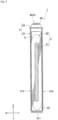
Fig. 1 is a perspective view illustrating an energy storage apparatus according to an embodiment. -
Fig. 2 is a perspective view illustrating an energy storage device in the energy storage apparatus. -
Fig. 3 is a side view of the energy storage device. -
Fig. 4 is a sectional view taken along a line IV-IV inFig. 2 . -
Fig. 5 is a sectional view taken along a line V-V inFig. 2 . -
Fig. 6A is a schematic plan view illustrating connection between an external terminal of the energy storage device and a bus bar. -
Fig. 6B is a schematic sectional view taken along a line VI-VI inFig. 6A . -
Fig. 7A is a schematic plan view illustrating connection between an external terminal and a bus bar of an energy storage device according to a comparative example. -
Fig. 7B is a schematic sectional view taken along a line VII-VII inFig. 7A . - An energy storage apparatus of the embodiment includes: an energy storage device including a metal external terminal; and a metal bus bar that is laminated on the external terminal and welded to the external terminal. A welded portion that welds the bus bar and the external terminal is formed on the bus bar, the welded portion is extended from the bus bar to the external terminal, the external terminal includes a clad material including a first metal layer adjacent to the bus bar and a second metal layer adjacent to the first metal layer, the welded portion welds the bus bar and the first metal layer, and an end of the welded portion does not reach an interface between the first metal layer and the second metal layer.
- According to the above configuration, the welded portion does not reach the interface between the metal layers constituting the clad material, so that the bonding strength of each metal layer constituting the clad material can be secured.
- In the energy storage apparatus, the welded portion may include a first welded portion and a second welded portion that partially overlap each other.
- According to the above configuration, the bonding strength between the bus bar and the external terminal can be ensured by ensuring a wide bonding width of the welded portion.
- In the energy storage apparatus, in a section of the external terminal and the bus bar in a laminating direction of the external terminal and the bus bar, a dimension in a direction orthogonal to the laminating direction at a boundary position between the external terminal and the bus bar may be larger than a thickness of the first metal layer.
- According to the above configuration, because the dimension (dimension in the direction orthogonal to the laminating direction) of the welded portion is secured at the boundary position between the external terminal and the bus bar, the bonding strength between the bus bar and the external terminal can be secured, whereby the bonding strength between the bus bar and the external terminal can be secured while the bonding strength between the metal layers of the clad material is secured.
- In the energy storage apparatus, the welded portion when viewed from the laminating direction of the external terminal and the bus bar may have an annular shape having no corner or an arc shape having no corner.
- According to the above configuration, since the welded portion has an annular shape or an arc shape without a corner portion, even if a force is applied to the welded portion, the force is less likely to concentrate on a part of the welded portion.
- An energy storage apparatus of the embodiment includes: an energy storage device including a metal external terminal; and a bus bar that is formed of a metal containing aluminum, the aluminum being laminated on the external terminal and welded to the external terminal. A welded portion that welds the bus bar and the external terminal is formed on the bus bar, the welded portion is extended from the bus bar to the external terminal, the external terminal includes a positive electrode external terminal and a negative electrode external terminal, the positive electrode external terminal is made of a metal containing aluminum, the negative electrode external terminal includes a clad material including a first metal layer adjacent to the bus bar and a second metal layer adjacent to the first metal layer, the first metal layer is formed of a metal containing aluminum, the second metal layer is formed of a metal containing copper, the welded portion welds the bus bar and the first metal layer, and an end of the welded portion does not reach an interface between the first metal layer and the second metal layer.
- According to the above configuration, the welded portion does not reach the interface between the metal layers constituting the clad material, so that the bonding strength of each metal layer constituting the clad material can be secured.
- A method for manufacturing an energy storage apparatus of the embodiment includes: laminating a metal bus bar on a metal external terminal of an energy storage device; applying heat to the bus bar from a side opposite to the external terminal to weld the bus bar and the external terminal; and forming a welded portion that welds the bus bar and the external terminal to each other on the bus bar. The welded portion is extended from the bus bar to the external terminal, the external terminal includes a clad material including a first metal layer adjacent to the bus bar and a second metal layer adjacent to the first metal layer, the welded portion welds the bus bar and the first metal layer, and an end of the welded portion does not reach an interface between the first metal layer and the second metal layer.
- According to the above configuration, the welded portion does not reach the interface between the metal layers constituting the clad material, the energy storage apparatus in which the bonding strength of each metal layer constituting the clad material is ensured can be manufactured.
- In the method for manufacturing the energy storage apparatus, the welded portion may be formed in an annular shape having no corner or an arc shape having no corner when viewed from a laminating direction of the external terminal and the bus bar.
- According to the above configuration, when the welding is performed with a general welding width, an annular or arc-shaped welded portion having no corner where force is hardly concentrated on one portion can be formed.
- From the above, the energy storage apparatus including the energy storage device in which the external terminal is formed of the clad material and the bus bar is connected to the external terminal, the energy storage apparatus in which the decrease in bonding strength between metal layers constituting the clad material is prevented, and a method for manufacturing the energy storage apparatus can be provided.
- Hereinafter, an embodiment of the present invention will be described with reference to
Figs. 1 to 7B . In the embodiment, a chargeable and dischargeable secondary battery will be described as an example of the energy storage device. Names of the constituent members (constituent elements) of the embodiment are those in the embodiment, and are sometimes different from the names of the constituent members (constituent elements) in the background art. - As illustrated in
Fig. 1 , anenergy storage apparatus 11 includes anenergy storage device 1 including a metalexternal terminal 4 and ametal bus bar 6 that is laminated on theexternal terminal 4 and welded to theexternal terminal 4. As illustrated inFig. 6B , in thebus bar 6 of theenergy storage apparatus 11, a weldedportion 7 that welds theexternal terminal 4 and thebus bar 6 is formed at a joining position between theexternal terminal 4 and thebus bar 6. Theenergy storage apparatus 11 of the embodiment includes a plurality of energy storage devices 1 (seeFig. 1 ). - The plurality of
energy storage devices 1 are arranged in a predetermined direction (first direction). For example, the first direction is a direction orthogonal to a laminating direction of theexternal terminal 4 and thebus bar 6. Each of the plurality ofenergy storage devices 1 is a primary battery, a secondary battery, a capacitor, or the like. Theenergy storage device 1 of the embodiment is a nonaqueous electrolyte secondary battery that can be charged and discharged. More specifically, theenergy storage device 1 is a lithium ion secondary battery utilizing electron transfer caused by transfer of the lithium ion. Theenergy storage device 1 is what is called a prismatic lithium ion secondary battery. - As illustrated in
Figs. 2 to 5 , theenergy storage device 1 includes anelectrode assembly 2 including a positive electrode and a negative electrode, acase 3 accommodating theelectrode assembly 2, and theexternal terminal 4 that is disposed outside thecase 3 and electrically connected to theelectrode assembly 2. In addition to theelectrode assembly 2, thecase 3 and theexternal terminal 4, theenergy storage device 1 includes acurrent collector 5 that makes theelectrode assembly 2 and theexternal terminal 4 conductive with each other. - The
electrode assembly 2 includes a windingcore 21 and alayered product 22 in which a positive electrode and a negative electrode are insulated from each other and laminated, thelayered product 22 being wound around a winding core 21 (seeFig. 5 ). When the lithium ion moves between the positive electrode and the negative electrode in theelectrode assembly 2, theenergy storage device 1 is charged and discharged. - For example, the positive electrode includes a strip-shaped metal foil and a positive active material layer formed on the metal foil. For example, the negative electrode includes a strip-shaped metal foil and a negative active material layer formed on the metal foil.
- In the
electrode assembly 2 of the embodiment, the positive electrode and the negative electrode are wound while being insulated from each other by a separator. That is, in theelectrode assembly 2 of the embodiment, the layered product of the positive electrode, the negative electrode, and the separator is wound. The separator is a member having an insulating property. The separator is disposed between the positive electrode and the negative electrode. Thus, in the electrode assembly 2 (particularly, the layered product), the positive electrode and the negative electrode are insulated from each other. The separator holds the electrolyte solution in thecase 3. Thus, during charge-discharge of theenergy storage device 1, the lithium ion moves between the positive electrode and the negative electrode that are alternately layered with the separator interposed therebetween. - The
case 3 includes acase body 31 including an opening, and alid plate 32 that closes the opening of thecase body 31. Thecase 3 accommodates the electrolyte solution in aninternal space 33 together with theelectrode assembly 2, thecurrent collector 5, and the like. Thecase 3 is made of metal having resistance to the electrolyte solution. For example, thecase 3 of the embodiment is formed of aluminum or a metal material containing aluminum such as an aluminum alloy. Thecase 3 may be formed of a metal material such as stainless steel and nickel, a composite material obtained by bonding resin such as nylon to aluminum, or the like. - The electrolyte solution is a non-aqueous solution electrolytic solution. The electrolyte solution is obtained by dissolving an electrolyte salt in an organic solvent. Examples of the organic solvent include cyclic carbonate esters such as propylene carbonate and ethylene carbonate, and chain carbonates such as dimethyl carbonate, diethyl carbonate, and ethyl methyl carbonate. Examples of the electrolyte salt include LiClO4, LiBF4, and LiPFs.
- The
case 3 is formed by overlapping and joining an opening peripheral edge of thecase body 31 and a peripheral edge of the lid plate 32 (seeFig. 4 ). Thecase 3 includes aninternal space 33 defined by thecase body 31 and thelid plate 32. In the embodiment, the opening peripheral edge of thecase body 31 and the peripheral edge of thelid plate 32 are joined by welding. - The
case body 31 includes aclosing portion 311 that has a plate shape and includes an inner surface facing the inside of thecase 3 and an outer surface facing the outside of thecase 3, and acylindrical body portion 312 that is connected to a peripheral edge of the closingportion 311, extends to the inner surface side of the closingportion 311, and surrounds the inner surface of the closing portion 311 (seeFig. 2 ). - The closing
portion 311 is a member positioned at a lower end of the case body 31 (that is, a bottom wall of thecase body 31 is formed when the opening looks upward) when thecase body 31 is disposed such that the opening looks upward. The closingportion 311 has a rectangular shape as viewed in a normal direction of the closingportion 311. The four corners of the closingportion 311 have an arc shape. - Hereinafter, as illustrated in
Fig. 2 , a long side direction of the closingportion 311 is defined as an X-axis direction, a short side direction of the closingportion 311 is defined as a Y-axis direction, and the normal direction of the closingportion 311 is defined as a Z-axis direction. - The
lid plate 32 is a plate-like member that closes the opening of thecase body 31. Specifically, thelid plate 32 abuts on thecase body 31 so as to close the opening of thecase body 31. More specifically, the peripheral edge of thelid plate 32 overlaps with the opening peripheral edge of thecase body 31 such that thelid plate 32 closes the opening. A boundary portion between thelid plate 32 and thecase body 31 laminated in this manner is welded. Thus, thecase 3 is configured. - The
lid plate 32 includes agas release valve 321 capable of discharging gas in thecase 3 to the outside (seeFig. 3 ). Thegas release valve 321 discharges the gas from the inside of thecase 3 to the outside when internal pressure of thecase 3 increases to a predetermined pressure. - The
external terminal 4 is a member that is electrically connected to an external terminal of another energy storage device, an external device, or the like. Theexternal terminal 4 of the embodiment has anouter surface 40 that is a surface to which the bus bar or the like can be welded. Theouter surface 40 of the embodiment is a flat surface. Theexternal terminal 4 has a plate shape expanding along thelid plate 32. Particularly, a flange of theexternal terminal 4 has a rectangular plate shape as viewed in the Z-axis direction. - The
external terminal 4 has a flange that extends along thecase 3 outside thecase 3, and a shaft that extends from the flange, penetrates thecase 3, and is electrically connected to the electrode assembly 2 (seeFig. 4 ). Furthermore, theexternal terminal 4 includes an external terminal (positive electrode external terminal) 4a connected to the positive electrode and an external terminal (negative electrode external terminal) 4b connected to the negative electrode. - In the
external terminal 4a, aflange 401a and ashaft 402a are integrated. Theexternal terminal 4a is formed of aluminum or a metal material containing aluminum such as an aluminum alloy. - In the
external terminal 4b, aflange 401b and ashaft 402b are separate bodies (separate members). Theflange 401b and theshaft 402b are connected by swaging theshaft 402b. - The
external terminal 4b has a clad material including a plurality of (two layers in the example of the embodiment) metal layers laminated in the laminating direction (Z-axis direction) of thebus bar 6 and theexternal terminal 4. Specifically, in theexternal terminal 4b, theflange 401b is made of a clad material. The metal layers adjacent to each other in the plurality of metal layers are made of different kinds of metals. - For example, as illustrated in
Fig. 6B , the plurality of metal layers included in theflange 401b (external terminal 4b) include afirst metal layer 41 located closest to thebus bar 6 in the Z-axis direction (that is, adjacent to the bus bar 6), and asecond metal layer 42 adjacent to thefirst metal layer 41. Theflange 401b of the embodiment is configured of thefirst metal layer 41 and thesecond metal layer 42. For example, the thickness of thefirst metal layer 41 of the embodiment ranges from 0.2 mm to 1.0 mm, and the thickness of thesecond metal layer 42 ranges from 0.2 mm to 3.0 mm. The thickness of thefirst metal layer 41 and the thickness of thesecond metal layer 42 are not limited to these ranges. - For example, the
first metal layer 41 is formed of aluminum or a metal material containing aluminum such as an aluminum alloy. For example, thesecond metal layer 42 is formed of a metal material containing copper such as copper or a copper alloy. - The
current collector 5 is disposed in thecase 3 and directly or indirectly connected to theelectrode assembly 2 in a conductive manner (seeFigs. 4 and5 ). Thecurrent collector 5 is formed of a member having conductivity. - The
bus bar 6 connects the differentenergy storage devices 1 to each other or connects theenergy storage device 1 to an external input and output terminal or the like in a conductive manner (seeFig. 1 ). Thebus bar 6 of the embodiment is overlapped on theouter surface 40 of theexternal terminal 4 and welded to the external terminal 4 (seeFig. 6B ). In addition, thebus bar 6 of the embodiment is made of the same material as theexternal terminal 4a. Furthermore, thebus bar 6 of the embodiment is made of the same material as thefirst metal layer 41 of theexternal terminal 4b. Specifically, thebus bar 6 is formed of aluminum or a metal material containing aluminum such as an aluminum alloy. - The welded
portion 7 is a member formed by welding theexternal terminal 4b (particularly, theflange 401b) and the bus bar 6 (seeFigs. 6A and 6B ). The weldedportion 7 is extended from thebus bar 6 to theexternal terminal 4b, namely, formed between thebus bar 6 and theexternal terminal 4b. In other words, the weldedportion 7 is formed continuously from thebus bar 6 to theexternal terminal 4b. The weldedportion 7 of the embodiment is formed by laser welding between theexternal terminal 4b and thebus bar 6. The weldedportion 7 of the embodiment includes welding tracks 710, 720 that are a mark of a laser irradiation position (specifically, a mark due to a center of the laser irradiation position). The width of the laser beam with which thebus bar 6 is irradiated in the laser welding of the embodiment is less than or equal to 1.0 mm. - The method for manufacturing the
energy storage apparatus 11 includes a process of forming the weldedportion 7 when theexternal terminal 4b and thebus bar 6 are welded to each other. Specifically, the method for manufacturing theenergy storage apparatus 11 includes: laminating themetal bus bar 6 on the metalexternal terminal 4b of theenergy storage device 1; applying heat to thebus bar 6 from the side opposite to theexternal terminal 4b to weld thebus bar 6 and theexternal terminal 4b to each other; and forming the weldedportion 7 where thebus bar 6 and theexternal terminal 4b are welded to each other at the welding position between theexternal terminal 4b and thebus bar 6, namely, forming the weldedportion 7 between theexternal terminal 4b and thebus bar 6. In other words, the weldedportion 7 is formed continuously from thebus bar 6 to theexternal terminal 4b. - In the Z-axis direction, an
end 70 of the weldedportion 7 does not reach aninterface 43 between thefirst metal layer 41 and thesecond metal layer 42. Specifically, theend 70 of the weldedportion 7 exists in thefirst metal layer 41. More specifically, theend 70 of the weldedportion 7 is located closer onto the side of thebus bar 6 than theinterface 43 between thefirst metal layer 41 and the second metal layer 42 (seeFig. 6B ). That is, in the Z-axis direction, theend 70 is located in front of theinterface 43 between thefirst metal layer 41 and thesecond metal layer 42. - The
end 70 of the weldedportion 7 is an end on the side of theexternal terminal 4b out of both ends of the weldedportion 7 in the Z-axis direction. That is, theend 70 of the weldedportion 7 becomes a lower end of the weldedportion 7 when thecase body 31 is disposed such that the opening looks upward (that is, when thebus bar 6 is disposed above theexternal terminal 4b). - The welded
portion 7 of the embodiment includes a first weldedportion 71 and a second weldedportion 72 partially overlapping each other. Specifically, the first weldedportion 71 and the second weldedportion 72 overlap each other at least at a boundary position between theexternal terminal 4b and the bus bar 6 (theouter surface 40 of theexternal terminal 4b). The first weldedportion 71 includes afirst welding track 710, and the second weldedportion 72 includes a second welding track 720 (seeFig. 6A ). - In the dimension (width W1) of the welded
portion 7 in the direction along the boundary at the boundary position (particularly, theouter surface 40 of theflange 401b of theexternal terminal 4b) between theexternal terminal 4b and thebus bar 6 in the Z-axis direction, namely, in the section (seeFig. 6B ) in the direction crossing the welding tracks 710 and 720, the dimension W1 of the weldedportion 7 in the direction orthogonal to the Z-axis direction at the boundary position between theexternal terminal 4b and thebus bar 6 is larger than the thickness T1 of the first metal layer 41 (seeFig. 6B ). That is, the width W1 of the weldedportion 7 at this boundary position is larger than the thickness T1 of thefirst metal layer 41. - Furthermore, the shape of the welded
portion 7 viewed from the Z-axis direction is an annular shape without a corner (for example, an elliptic shape or a circular shape). That is, the weldedportion 7 is formed in an annular shape having no corner when viewed from the Z-axis direction. In the weldedportion 7 of the embodiment, the shape of thefirst welding track 710 and the shape of thesecond welding track 720 are both annular without corner (in the example ofFig. 6A , whet is called a racetrack type). In the weldedportion 7 of the embodiment, the welding track is formed in a plurality of concentric circles (for example, a double circle shape). - The
first welding track 710 is separated from thesecond welding track 720. Specifically, thefirst welding track 710 and thesecond welding track 720 are separated from each other in the range where the first weldedportion 71 and the second weldedportion 72 overlap each other at the boundary position between thebus bar 6 and theexternal terminal 4b. Thefirst welding track 710 is disposed inside thesecond welding track 720. - In the conventional energy storage apparatus, when the
external terminal 4b and thebus bar 6 are welded by the laser welding such that the welding track is formed around thebus bar 6, as illustrated inFigs. 7A and 7B , the depth of the penetration between theexternal terminal 4b and thebus bar 6 is increased in order to increase the width of the weldedportion 7 at the boundary position between theexternal terminal 4b and the bus bar 6 (theupper surface 40 of theexternal terminal 4b) for the purpose of securing the bonding strength between theexternal terminal 4b and thebus bar 6. Consequently, in the conventional energy storage apparatus, theend 70 of the weldedportion 7 reaches theinterface 43 between thefirst metal layer 41 and thesecond metal layer 42 that constitute the clad material, and sometimes the bonding strength between the metal layers 41 and 42 is not secured. - On the other hand, in the
energy storage apparatus 11 of the embodiment, because theend 70 of the weldedportion 7 is positioned in front of theinterface 43 between thefirst metal layer 41 and the second metal layer 42 (seeFig. 6B ), namely, because the weldedportion 7 does not reach theinterface 43 between thefirst metal layer 41 and thesecond metal layer 42 that constitute the clad material of theexternal terminal 4b, the bonding strength between the metal layers 41 and 42 that constitute the clad material is secured. The details are as follows. - In the case where the laser beam having a small spot diameter (less than or equal to 1.0 mm) is used for welding the
bus bar 6 and theexternal terminal 4b, when the width of the weldedportion 7 is small, the welding strength between theexternal terminal 4b and thebus bar 6 cannot be secured. On the other hand, when the penetration depth in the weldedportion 7 is increased in order to secure the welding strength, theend 70 of the weldedportion 7 reaches the interface between thefirst metal layer 41 and thesecond metal layer 42 of the external terminal (clad material) 4b to generate an alloy of copper and aluminum, so that the strength of theexternal terminal 4b (particularly, theflange 401b formed of the clad material) decreases. Therefore, like the method for manufacturing theenergy storage apparatus 11 of the embodiment, theend 70 of the weldedportion 7 does not reach theinterface 43 between thefirst metal layer 41 and thesecond metal layer 42 of the clad material (external terminal 4b) as a method for welding theexternal terminal 4b (flange 401b) and thebus bar 6 with the laser beam having the small spot diameter so as not to lower the interface strength of the clad material. At this point, the spot diameter of the laser welding in the embodiment is the width of the laser beam focused by the laser beam being narrowed at the focal position. That is, the width of the laser that focuses on the upper surface of thebus bar 6 is the spot diameter. - For example, specifically, like the
energy storage apparatus 11 of the embodiment, the first weldedportion 71 and the second weldedportion 72 partially overlap with each other to secure the wide bonding width of the weldedportion 7, so that the bonding strength between thebus bar 6 and theexternal terminal 4b can be secured. That is, as compared with the case where the first weldedportion 71 and the second weldedportion 72 are welded while being separated from each other (in the state where the first weldedportion 71 and the second weldedportion 72 do not overlap each other), when the first weldedportion 71 and the second weldedportion 72 partially overlap each other like theenergy storage apparatus 11 of the embodiment, an area (the size of the width W1, seeFig. 6(b) ) of the weldedportion 7 is secured, and the sufficient connection strength can be obtained at the connection (welding) member between thebus bar 6 and theexternal terminal 4b. - In the
energy storage apparatus 11 of the embodiment, the width W1 at the boundary position between theexternal terminal 4b of the weldedportion 7 and thebus bar 6 is larger than the thickness T1 of thefirst metal layer 41, so that the dimension of the weldedportion 7 is sufficiently secured at the boundary position. Consequently, the bonding strength between thebus bar 6 and theexternal terminal 4b can be secured. Thus, the bonding strength between thebus bar 6 and theexternal terminal 4b can be secured while the bonding strength between the metal layers 41 and 42 constituting the clad material is secured. - Like the
energy storage apparatus 11 of this embodiment, when the clad material including thefirst metal layer 41 made of aluminum and thesecond metal layer 42 made of the copper is made to constitute theexternal terminal 4b (particularly, theflange 401b), the electric resistance of theexternal terminal 4b can be restrained by making the width W1 of the weldedportion 7 at the boundary position between thebus bar 6 and theexternal terminal 4b larger than the thickness T1 of thefirst metal layer 41. That is, when the width W1 at the boundary position of the weldedportion 7 is made larger than the thickness T1 of thefirst metal layer 41 while theend 70 of the weldedportion 7 does not reach theinterface 43 between thefirst metal layer 41 and thesecond metal layer 42, the layer of aluminum (first metal layer 41) having electrical conductivity higher than that of copper is thinned while the welding strength between theexternal terminal 4b and thebus bar 6 is sufficiently secured, so that the electric resistance of the entireexternal terminal 4b can be restrained. - In the
energy storage apparatus 11 of the embodiment, thebus bar 6 and theexternal terminal 4b are cut at the position where thebus bar 6 and theexternal terminal 4b cross the welded portion 7 (welding tracks 710, 720), and the section (the section along the laminating direction) of thebus bar 6 and theexternal terminal 4b is etched, so that the penetration depth (the position of theend 70 in the Z-axis direction), the shape, the width W1, and the like of the weldedportion 7 can be checked because a corrosion speed is different between the weldedportion 7 and other portions. - Furthermore, in the
energy storage apparatus 11 of the embodiment, because the weldedportion 7 has the annular shape without the corner, force is hardly concentrated on a portion of the weldedportion 7 even when the force is applied to the weldedportion 7. In other words, the weldedportion 7 has the annular shape without the corner, so that stress concentration in the weldedportion 7 can be restrained. - In the method for manufacturing the
energy storage apparatus 11 described above, the weldedportion 7 does not reach the interface between the metal layers 41, 42 that constitute the clad material of theexternal terminal 4b, so that theenergy storage apparatus 11 in which the bonding strength between the metal layers 41, 42 constituting the clad material is secured can be manufactured. - In the method for manufacturing the
energy storage apparatus 11 of the embodiment, when the welding is performed with a general welding width, the annular weldedportion 7 having no corner where the force is hardly concentrated on one portion can be formed. - In the
energy storage apparatus 11 of the embodiment, theenergy storage devices 1 are arranged in the direction orthogonal to the laminating direction of theexternal terminals 4b and the bus bars 6. Thus, the laminated portion between theexternal terminal 4b and thebus bar 6 in eachenergy storage device 1 is not hidden by another energy storage device, so that the welding between theexternal terminal 4b and thebus bar 6 can be easily performed. In addition, the laminated portion of theexternal terminal 4b and thebus bar 6 is not hidden by another energy storage device, so that alignment of thebus bar 6 and theexternal terminal 4b before the welding is easy to perform. - It is needless to say that the energy storage apparatus and the method for manufacturing the energy storage apparatus of the present invention are not limited to the above-mentioned embodiment, and various modifications can be made without departing from the gist of the present invention. For example, the configuration of another embodiment can be added to the configuration of one embodiment, and a part of the configuration of one embodiment can be replaced with the configuration of another embodiment. Furthermore, a part of the configuration of an embodiment can be deleted.
- In the embodiment, the welded
portion 7 viewed from the Z-axis direction has the shape without the corner, but may be a shape with the corner (for example, a polygonal shape having the corner, a linear shape, and a polygonal line shape). - The welded
portion 7 viewed from the Z-axis direction preferably has the shape without the corner, and may be an arc shape without the corner. Even in this case, because the weldedportion 7 has the shape without the corner, the force does not concentrate on a part of the weldedportion 7 even when the force is applied to the weldedportion 7. When the weldedportion 7 has the arc shape, the arc shape having a length greater than or equal to a semicircle is more preferable from the viewpoint of ensuring the bonding strength between theexternal terminal 4b constituting the clad material and thebus bar 6. - Furthermore, the shape of the welded
portion 7 viewed from the Z-axis direction may be a spiral shape without a corner or the like. The shape of the weldedportion 7 as viewed from the Z-axis direction may be a curved shape or the like. - Although the welded
portion 7 includes thefirst welding track 710 and thesecond welding track 720 as two welding tracks, the weldedportion 7 may include one welding track or at least three welding tracks. When the weldedportion 7 includes the plurality of welding tracks, the plurality of welding tracks may be separated from each other or partially overlap each other. When the plurality of welding tracks overlap each other in the weldedportion 7, the output of the welding may be limited (adjusted) such that theend 70 of the weldedportion 7 does not reach theinterface 43 between the metal layers 41, 42. - The dimension (dimension of the width W1) of the welded
portion 7 at the boundary position between theexternal terminal 4b and thebus bar 6 in the Z-axis direction (theouter surface 40 of the external terminal 4) in the direction along this boundary is larger than the thickness T1 of thefirst metal layer 41, but may be the same as the thickness T1 of thefirst metal layer 41 or be smaller than the thickness T1 of thefirst metal layer 41. - In the embodiment, the flange (clad material) 401b of the
external terminal 4b is constituted of two metal layers, but may be constituted of a plurality of metal layers of at least three layers. Also in this case, theend 70 of the weldedportion 7 is positioned closer to thebus bar 6 than the interface between thefirst metal layer 41 adjacent to thebus bar 6 and thesecond metal layer 42 adjacent to thefirst metal layer 41 in the flange (clad material) 401b of theexternal terminal 4b, so that the configuration in which the weldedportion 7 does not reach theinterface 43 between the metal layers 41, 42 constituting the clad material can be implemented. - Furthermore, in the embodiment, the
energy storage apparatus 11 includes the plurality ofenergy storage devices 1. However, theenergy storage apparatus 11 may include oneenergy storage device 1. - In the embodiment, the case where the energy storage device is used as the nonaqueous electrolyte secondary battery (for example, the lithium ion secondary battery) that can be charged and discharged has been described. However, the type and the size (capacity) of the energy storage device are arbitrary. In the embodiment, the lithium ion secondary battery has been described as an example of the energy storage device, but the present invention is not limited thereto. For example, the present invention is also applicable to various secondary batteries, primary batteries, and energy storage devices of capacitors such as an electric double layer capacitor.
- In order to express the present invention, the present invention has been appropriately and sufficiently described above through the embodiment with reference to the drawings, but it should be recognized that a person skilled in the art can easily modify and/or improve the embodiment. Accordingly, as long as the modification or improvement implemented by those skilled in the art are not at a level departing from the scope of the claims described in the claims, the modification or improvement is interpreted to be included in the scope of the claims.
-
- 1: energy storage device
- 2: electrode assembly
- 3: case
- 4, 4a, 4b: external terminal
- 5: current collector
- 6: bus bar
- 7: welded portion
- 11: energy storage apparatus
- 21: winding core
- 22: layered product
- 31: case body
- 32: lid plate
- 33: internal space
- 40: outer surface (upper surface)
- 41: first metal layer (metal layer)
- 42: second metal layer (metal layer)
- 43: interface
- 70: end
- 71: first welded portion
- 72: second welded portion
- 311: closing portion
- 312: body portion
- 321: gas release valve
- 401a, 401b: flange
- 402a, 402b: shaft
- 710: first welding track
- 720: second welding track
- W1: width
Claims (7)
- An energy storage apparatus comprising:an energy storage device including a metal external terminal; anda metal bus bar that is laminated on the external terminal and welded to the external terminal,wherein a welded portion that welds the bus bar and the external terminal is formed on the bus bar,the welded portion is extended from the bus bar to the external terminal,the external terminal includes a clad material including a first metal layer adjacent to the bus bar and a second metal layer adjacent to the first metal layer,the welded portion welds the bus bar and the first metal layer, andan end of the welded portion does not reach an interface between the first metal layer and the second metal layer.
- The energy storage apparatus according to claim 1, wherein the welded portion includes a first welded portion and a second welded portion that partially overlap each other.
- The energy storage apparatus according to claim 1 or 2, wherein in a section of the external terminal and the bus bar in a laminating direction of the external terminal and the bus bar, a dimension of the welded portion at a boundary position between the external terminal and the bus bar in a direction orthogonal to the laminating direction is larger than a thickness of the first metal layer.
- The energy storage apparatus according to any one of claims 1 to 3, wherein the welded portion when viewed from the laminating direction of the external terminal and the bus bar has an annular shape having no corner or an arc shape having no corner.
- An energy storage apparatus comprising:an energy storage device including a metal external terminal; anda bus bar that is formed of a metal containing aluminum, the aluminum being laminated on the external terminal and welded to the external terminal,wherein a welded portion that welds the bus bar and the external terminal is formed on the bus bar,the welded portion is extended from the bus bar to the external terminal,the external terminal includes a positive electrode external terminal and a negative electrode external terminal,the positive electrode external terminal is made of a metal containing aluminum,the negative electrode external terminal includes a clad material including a first metal layer adjacent to the bus bar and a second metal layer adjacent to the first metal layer,the first metal layer is formed of a metal containing aluminum,the second metal layer is formed of a metal containing copper,the welded portion welds the bus bar and the first metal layer, andan end of the welded portion does not reach an interface between the first metal layer and the second metal layer.
- A method for manufacturing an energy storage apparatus, comprising:laminating a metal bus bar on a metal external terminal of an energy storage device;applying heat to the bus bar from a side opposite to the external terminal to weld the bus bar and the external terminal; andforming a welded portion that welds the bus bar and the external terminal to each other on the bus bar,wherein the welded portion is extended from the bus bar to the external terminal,the external terminal includes a clad material including a first metal layer adjacent to the bus bar and a second metal layer adjacent to the first metal layer,the welded portion welds the bus bar and the first metal layer, andan end of the welded portion does not reach an interface between the first metal layer and the second metal layer.
- The method for manufacturing the energy storage apparatus according to claim 6, wherein the welded portion is formed in an annular shape having no corner or an arc shape having no corner when viewed from a laminating direction of the external terminal and the bus bar.
Applications Claiming Priority (2)
| Application Number | Priority Date | Filing Date | Title |
|---|---|---|---|
| JP2020082644 | 2020-05-08 | ||
| PCT/JP2021/010769 WO2021225035A1 (en) | 2020-05-08 | 2021-03-17 | Electricity storage device and method for manufacturing electricity storage device |
Publications (2)
| Publication Number | Publication Date |
|---|---|
| EP4148756A1 true EP4148756A1 (en) | 2023-03-15 |
| EP4148756A4 EP4148756A4 (en) | 2023-10-18 |
Family
ID=78468016
Family Applications (1)
| Application Number | Title | Priority Date | Filing Date |
|---|---|---|---|
| EP21800848.0A Pending EP4148756A4 (en) | 2020-05-08 | 2021-03-17 | ELECTRICITY STORAGE DEVICE AND METHOD FOR MANUFACTURING AN ELECTRICITY STORAGE DEVICE |
Country Status (5)
| Country | Link |
|---|---|
| US (1) | US20230163424A1 (en) |
| EP (1) | EP4148756A4 (en) |
| JP (1) | JP7808280B2 (en) |
| CN (1) | CN115552714A (en) |
| WO (1) | WO2021225035A1 (en) |
Families Citing this family (1)
| Publication number | Priority date | Publication date | Assignee | Title |
|---|---|---|---|---|
| US20250196790A1 (en) * | 2023-12-19 | 2025-06-19 | GM Global Technology Operations LLC | Methods of Joining Multilayer Copper-Graphene Coated Current Collectors to Battery Cans and Between Windings in Electric Motor Stators |
Family Cites Families (12)
| Publication number | Priority date | Publication date | Assignee | Title |
|---|---|---|---|---|
| WO2013065523A1 (en) | 2011-10-31 | 2013-05-10 | 三洋電機株式会社 | Cell assembly, and rectangular secondary cell for use in cell assembly |
| JP6176524B2 (en) | 2013-06-25 | 2017-08-09 | 株式会社Gsユアサ | Power storage device and method for manufacturing power storage device |
| JP6070490B2 (en) * | 2013-09-11 | 2017-02-01 | 日立金属株式会社 | Battery terminal and battery terminal manufacturing method |
| JP5943396B2 (en) * | 2013-09-25 | 2016-07-05 | 株式会社日立金属ネオマテリアル | Battery terminal, battery terminal manufacturing method and battery |
| WO2015186168A1 (en) * | 2014-06-02 | 2015-12-10 | 日産自動車株式会社 | Laser welding method and battery pack |
| JP6363893B2 (en) | 2014-07-08 | 2018-07-25 | 日立オートモティブシステムズ株式会社 | Secondary battery |
| JP6581440B2 (en) | 2014-10-24 | 2019-09-25 | 日立金属株式会社 | Battery terminal, battery terminal manufacturing method and battery |
| JP6014808B1 (en) * | 2015-08-17 | 2016-10-26 | 日立金属株式会社 | Battery terminal and battery terminal manufacturing method |
| JP6660533B2 (en) * | 2015-09-15 | 2020-03-11 | パナソニックIpマネジメント株式会社 | Welding structure and welding method for metal members |
| JP6814389B2 (en) | 2017-04-10 | 2021-01-20 | トヨタ自動車株式会社 | Batteries |
| JP2020082644A (en) | 2018-11-30 | 2020-06-04 | 株式会社平安コーポレーション | Dust collection mechanism for wood processing machine |
| JP7296208B2 (en) | 2018-12-27 | 2023-06-22 | 三洋電機株式会社 | Secondary battery and assembled battery |
-
2021
- 2021-03-17 JP JP2022519903A patent/JP7808280B2/en active Active
- 2021-03-17 WO PCT/JP2021/010769 patent/WO2021225035A1/en not_active Ceased
- 2021-03-17 CN CN202180033249.0A patent/CN115552714A/en active Pending
- 2021-03-17 EP EP21800848.0A patent/EP4148756A4/en active Pending
- 2021-05-17 US US17/923,085 patent/US20230163424A1/en active Pending
Also Published As
| Publication number | Publication date |
|---|---|
| US20230163424A1 (en) | 2023-05-25 |
| WO2021225035A1 (en) | 2021-11-11 |
| EP4148756A4 (en) | 2023-10-18 |
| JP7808280B2 (en) | 2026-01-29 |
| JPWO2021225035A1 (en) | 2021-11-11 |
| CN115552714A (en) | 2022-12-30 |
Similar Documents
| Publication | Publication Date | Title |
|---|---|---|
| JP6657843B2 (en) | Rechargeable battery | |
| CN106257711B (en) | Secondary battery and battery pack using the same | |
| EP2254176B1 (en) | Rechargeable battery | |
| US12176580B2 (en) | Secondary battery and method for manufacturing same | |
| JP5856858B2 (en) | Method for manufacturing prismatic secondary battery | |
| JP5300788B2 (en) | Secondary battery | |
| KR102568341B1 (en) | Energy storage device | |
| US10326169B2 (en) | Method for manufacturing prismatic secondary battery | |
| US11316235B2 (en) | Prismatic secondary battery, assembled battery using the same and method of producing the same | |
| CN114223096A (en) | Secondary battery and method for manufacturing same | |
| US10177363B2 (en) | Prismatic secondary battery | |
| JP6582443B2 (en) | Secondary battery and manufacturing method thereof | |
| US9882236B2 (en) | Prismatic secondary battery | |
| JP2019106274A (en) | Square secondary battery and manufacturing method thereof | |
| US10424809B2 (en) | Secondary battery, method for manufacturing same, and battery pack employing same | |
| US11024925B2 (en) | Secondary battery and method of manufacturing the same | |
| KR20200102177A (en) | Secondary battery and manufacturing method therof | |
| CN109585770B (en) | Secondary battery and method for manufacturing same | |
| JP6641842B2 (en) | Prismatic rechargeable battery | |
| EP4148756A1 (en) | Electricity storage device and method for manufacturing electricity storage device | |
| JP6375610B2 (en) | Storage element and method for manufacturing the same | |
| JP7405687B2 (en) | Energy storage element | |
| US20260051633A1 (en) | Secondary Battery and Manufacturing Method Thereof | |
| US20240413493A1 (en) | Secondary battery | |
| JP2019032991A (en) | Sealed battery |
Legal Events
| Date | Code | Title | Description |
|---|---|---|---|
| STAA | Information on the status of an ep patent application or granted ep patent |
Free format text: STATUS: THE INTERNATIONAL PUBLICATION HAS BEEN MADE |
|
| PUAI | Public reference made under article 153(3) epc to a published international application that has entered the european phase |
Free format text: ORIGINAL CODE: 0009012 |
|
| STAA | Information on the status of an ep patent application or granted ep patent |
Free format text: STATUS: REQUEST FOR EXAMINATION WAS MADE |
|
| 17P | Request for examination filed |
Effective date: 20221114 |
|
| AK | Designated contracting states |
Kind code of ref document: A1 Designated state(s): AL AT BE BG CH CY CZ DE DK EE ES FI FR GB GR HR HU IE IS IT LI LT LU LV MC MK MT NL NO PL PT RO RS SE SI SK SM TR |
|
| DAV | Request for validation of the european patent (deleted) | ||
| DAX | Request for extension of the european patent (deleted) | ||
| REG | Reference to a national code |
Ref country code: DE Ref legal event code: R079 Free format text: PREVIOUS MAIN CLASS: H01G0011120000 Ipc: H01G0011100000 |
|
| A4 | Supplementary search report drawn up and despatched |
Effective date: 20230920 |
|
| RIC1 | Information provided on ipc code assigned before grant |
Ipc: H01G 11/08 20130101ALN20230914BHEP Ipc: H01G 11/12 20130101ALN20230914BHEP Ipc: H01M 50/50 20210101ALI20230914BHEP Ipc: H01M 50/176 20210101ALI20230914BHEP Ipc: H01M 50/566 20210101ALI20230914BHEP Ipc: H01M 50/553 20210101ALI20230914BHEP Ipc: H01M 50/55 20210101ALI20230914BHEP Ipc: H01M 50/534 20210101ALI20230914BHEP Ipc: H01M 50/528 20210101ALI20230914BHEP Ipc: H01M 50/522 20210101ALI20230914BHEP Ipc: H01M 50/507 20210101ALI20230914BHEP Ipc: H01M 50/505 20210101ALI20230914BHEP Ipc: H01M 50/503 20210101ALI20230914BHEP Ipc: H01M 50/103 20210101ALI20230914BHEP Ipc: H01M 10/0525 20100101ALI20230914BHEP Ipc: H01G 11/82 20130101ALI20230914BHEP Ipc: H01G 11/76 20130101ALI20230914BHEP Ipc: H01M 50/562 20210101ALI20230914BHEP Ipc: H01M 50/516 20210101ALI20230914BHEP Ipc: H01G 11/10 20130101AFI20230914BHEP |