EP4148671B1 - Elektronische vorrichtung und verfahren zur steuerung davon - Google Patents
Elektronische vorrichtung und verfahren zur steuerung davon Download PDFInfo
- Publication number
- EP4148671B1 EP4148671B1 EP21850284.7A EP21850284A EP4148671B1 EP 4148671 B1 EP4148671 B1 EP 4148671B1 EP 21850284 A EP21850284 A EP 21850284A EP 4148671 B1 EP4148671 B1 EP 4148671B1
- Authority
- EP
- European Patent Office
- Prior art keywords
- depth image
- image
- depth
- composition ratio
- electronic device
- Prior art date
- Legal status (The legal status is an assumption and is not a legal conclusion. Google has not performed a legal analysis and makes no representation as to the accuracy of the status listed.)
- Active
Links
Images


Classifications
-
- G—PHYSICS
- G06—COMPUTING OR CALCULATING; COUNTING
- G06T—IMAGE DATA PROCESSING OR GENERATION, IN GENERAL
- G06T7/00—Image analysis
- G06T7/50—Depth or shape recovery
- G06T7/55—Depth or shape recovery from multiple images
-
- G—PHYSICS
- G06—COMPUTING OR CALCULATING; COUNTING
- G06T—IMAGE DATA PROCESSING OR GENERATION, IN GENERAL
- G06T7/00—Image analysis
- G06T7/50—Depth or shape recovery
- G06T7/55—Depth or shape recovery from multiple images
- G06T7/593—Depth or shape recovery from multiple images from stereo images
- G06T7/596—Depth or shape recovery from multiple images from stereo images from three or more stereo images
-
- G—PHYSICS
- G06—COMPUTING OR CALCULATING; COUNTING
- G06T—IMAGE DATA PROCESSING OR GENERATION, IN GENERAL
- G06T7/00—Image analysis
- G06T7/50—Depth or shape recovery
- G06T7/55—Depth or shape recovery from multiple images
- G06T7/593—Depth or shape recovery from multiple images from stereo images
-
- G—PHYSICS
- G01—MEASURING; TESTING
- G01S—RADIO DIRECTION-FINDING; RADIO NAVIGATION; DETERMINING DISTANCE OR VELOCITY BY USE OF RADIO WAVES; LOCATING OR PRESENCE-DETECTING BY USE OF THE REFLECTION OR RERADIATION OF RADIO WAVES; ANALOGOUS ARRANGEMENTS USING OTHER WAVES
- G01S17/00—Systems using the reflection or reradiation of electromagnetic waves other than radio waves, e.g. lidar systems
- G01S17/87—Combinations of systems using electromagnetic waves other than radio waves
-
- G—PHYSICS
- G01—MEASURING; TESTING
- G01S—RADIO DIRECTION-FINDING; RADIO NAVIGATION; DETERMINING DISTANCE OR VELOCITY BY USE OF RADIO WAVES; LOCATING OR PRESENCE-DETECTING BY USE OF THE REFLECTION OR RERADIATION OF RADIO WAVES; ANALOGOUS ARRANGEMENTS USING OTHER WAVES
- G01S17/00—Systems using the reflection or reradiation of electromagnetic waves other than radio waves, e.g. lidar systems
- G01S17/88—Lidar systems specially adapted for specific applications
- G01S17/89—Lidar systems specially adapted for specific applications for mapping or imaging
- G01S17/894—3D imaging with simultaneous measurement of time-of-flight at a 2D array of receiver pixels, e.g. time-of-flight cameras or flash lidar
-
- G—PHYSICS
- G06—COMPUTING OR CALCULATING; COUNTING
- G06T—IMAGE DATA PROCESSING OR GENERATION, IN GENERAL
- G06T3/00—Geometric image transformations in the plane of the image
- G06T3/40—Scaling of whole images or parts thereof, e.g. expanding or contracting
-
- G—PHYSICS
- G06—COMPUTING OR CALCULATING; COUNTING
- G06T—IMAGE DATA PROCESSING OR GENERATION, IN GENERAL
- G06T5/00—Image enhancement or restoration
- G06T5/50—Image enhancement or restoration using two or more images, e.g. averaging or subtraction
-
- G—PHYSICS
- G06—COMPUTING OR CALCULATING; COUNTING
- G06T—IMAGE DATA PROCESSING OR GENERATION, IN GENERAL
- G06T7/00—Image analysis
- G06T7/10—Segmentation; Edge detection
- G06T7/11—Region-based segmentation
-
- G—PHYSICS
- G06—COMPUTING OR CALCULATING; COUNTING
- G06T—IMAGE DATA PROCESSING OR GENERATION, IN GENERAL
- G06T7/00—Image analysis
- G06T7/50—Depth or shape recovery
- G06T7/521—Depth or shape recovery from laser ranging, e.g. using interferometry; from the projection of structured light
-
- G—PHYSICS
- G06—COMPUTING OR CALCULATING; COUNTING
- G06T—IMAGE DATA PROCESSING OR GENERATION, IN GENERAL
- G06T7/00—Image analysis
- G06T7/90—Determination of colour characteristics
-
- G—PHYSICS
- G06—COMPUTING OR CALCULATING; COUNTING
- G06V—IMAGE OR VIDEO RECOGNITION OR UNDERSTANDING
- G06V10/00—Arrangements for image or video recognition or understanding
- G06V10/20—Image preprocessing
- G06V10/22—Image preprocessing by selection of a specific region containing or referencing a pattern; Locating or processing of specific regions to guide the detection or recognition
-
- G—PHYSICS
- G06—COMPUTING OR CALCULATING; COUNTING
- G06T—IMAGE DATA PROCESSING OR GENERATION, IN GENERAL
- G06T2207/00—Indexing scheme for image analysis or image enhancement
- G06T2207/10—Image acquisition modality
- G06T2207/10004—Still image; Photographic image
- G06T2207/10012—Stereo images
-
- G—PHYSICS
- G06—COMPUTING OR CALCULATING; COUNTING
- G06T—IMAGE DATA PROCESSING OR GENERATION, IN GENERAL
- G06T2207/00—Indexing scheme for image analysis or image enhancement
- G06T2207/10—Image acquisition modality
- G06T2207/10024—Color image
-
- G—PHYSICS
- G06—COMPUTING OR CALCULATING; COUNTING
- G06T—IMAGE DATA PROCESSING OR GENERATION, IN GENERAL
- G06T2207/00—Indexing scheme for image analysis or image enhancement
- G06T2207/10—Image acquisition modality
- G06T2207/10028—Range image; Depth image; 3D point clouds
-
- G—PHYSICS
- G06—COMPUTING OR CALCULATING; COUNTING
- G06T—IMAGE DATA PROCESSING OR GENERATION, IN GENERAL
- G06T2207/00—Indexing scheme for image analysis or image enhancement
- G06T2207/20—Special algorithmic details
- G06T2207/20212—Image combination
-
- G—PHYSICS
- G06—COMPUTING OR CALCULATING; COUNTING
- G06T—IMAGE DATA PROCESSING OR GENERATION, IN GENERAL
- G06T2207/00—Indexing scheme for image analysis or image enhancement
- G06T2207/20—Special algorithmic details
- G06T2207/20212—Image combination
- G06T2207/20221—Image fusion; Image merging
Definitions
- the disclosure relates to an electronic device and a method for controlling the same, and more particularly, to an electronic device for acquiring a depth image and a method for controlling the same.
- a sensor for acquiring depth information there are a time of flight (ToF) sensor that acquires a depth image based on flight time or phase information of light, a stereo camera for acquiring a depth image based on an image captured by two cameras, and the like.
- ToF time of flight
- the ToF sensor has superior angular resolution for a long distance compared to the stereo camera, but has a limitation in that the accuracy of near-field information is relatively low due to multiple reflections.
- the stereo camera may acquire short-distance information with relatively high accuracy, two cameras need to be far apart from each other for long-distance measurement, so the stereo cameras have the disadvantage of being difficult to manufacture small in size.
- WALAS KRZYSZTOF ET AL "Depth data fusion for simultaneous localization and mapping - RGB-DD SLAM",2016 IEEE INTERNATIONAL CONFERENCE ON MULTISENSOR FUSION AND INTEGRATION FOR INTELLIGENT SYSTEMS (MFI), IEEE, 19 September 2016 (2016-09-19), pages 9-14 , mentions the problem of depth acquisition of sensors of different characteristics and merges both with one depth map having a confidence map.
- LASANG PONGSAK ET AL "Optimal depth recovery using image guided TGV with depth confidence for high-quality view synthesis", JOURNAL OF VISUAL COMMUNICATION AND IMAGE REPRESENTATION, ACADEMIC PRESS, INC, US, vol. 39, 12 May 2016 (2016-05-12), pages 24-39 , improves acquired depth data using confidence and RGB.
- the disclosure provides an electronic device that is easy to miniaturize and has improved accuracy of distance information for a short distance.
- an electronic device includes: a first image sensor; a second image sensor; and a processor, in which the processor is configured to acquire a first depth image and a confidence map corresponding to the first depth image by using the first image sensor, is configured to acquire an RGB image corresponding to the first depth image by using the second image sensor, is configured to acquire a second depth image based on the confidence map and the RGB image, and is configured to acquire a third depth image by composing the first depth image and the second depth image based on a pixel value of the confidence map.
- the processor may be configured to acquire a grayscale image for the RGB image, and the second depth image may be acquired by stereo matching the confidence map and the grayscale image.
- the processor may be configured to acquire the second depth image by stereo matching the confidence map and the grayscale image based on a shape of an object included in the confidence map and the grayscale image.
- the processor may be configured to determine a composition ratio of the first depth image and the second depth image based on the pixel value of the confidence map; and to acquire a third depth image by composing the first depth image and the second depth image based on the determined composition ratio.
- the processor may be configured to determine the first composition ratio and the second composition ratio so that the first composition ratio of the first depth image is greater than the second composition ratio of the second depth image for a region in which a pixel value is greater than a preset value among a plurality of regions of the confidence map, and the first composition ratio and the second composition ratio may be determined so that the first composition ratio is smaller than the second composition ratio for the region in which the pixel value is smaller than the preset value among a plurality of regions of the confidence map.
- the processor may be configured to acquire a depth value of the second depth image as a depth value of the third depth image for a first region in which a depth value is smaller than a first threshold distance among a plurality of regions of the first depth image, and to acquire a depth value of the first depth image as a depth value of the third depth image for a second region in which a depth value is greater than a second threshold distance among a plurality of regions of the first depth image.
- the processor may be configured to identify an object included in the RGB image, to identify each region of the first depth image and the second depth image corresponding to the identified object, and to acquire the third depth image by composing the first depth image and the second depth image at a predetermined composition ratio for each of the regions.
- the first image sensor may be a time of flight (ToF) sensor
- the second image sensor may be an RGB sensor
- a method for controlling an electronic device includes: acquiring a first depth image and a confidence map corresponding to the first depth image by using a first image sensor; acquiring an RGB image corresponding to the first depth image by using a second image sensor; acquiring a second depth image based on the confidence map and the RGB image; and acquiring a third depth image by composing the first depth image and the second depth image based on a pixel value of the confidence map.
- a grayscale image for the RGB image may be acquired, and the second depth image may be acquired by stereo matching the confidence map and the grayscale image.
- the second depth image may be acquired by stereo matching the confidence map and the grayscale image based on a shape of an object included in the confidence map and the grayscale image.
- a composition ratio of the first depth image and the second depth image may be determined based on the pixel value of the confidence map, and a third depth image may be acquired by composing the first depth image and the second depth image based on the determined composition ratio.
- the first composition ratio and the second composition ratio may be determined so that the first composition ratio of the first depth image is greater than the second composition ratio of the second depth image for a region in which a pixel value is greater than a preset value among a plurality of regions of the confidence map, and the first composition ratio and the second composition ratio may be determined so that the first composition ratio is smaller than the second composition ratio for the region in which the pixel value is smaller than the preset value among a plurality of regions of the confidence map.
- a depth value of the second depth image may be acquired as a depth value of the third depth image for a first region in which a depth value is smaller than a first threshold distance among a plurality of regions of the first depth image
- a depth value of the first depth image may be acquired as a depth value of the third depth image for a second region in which a depth value is larger than a second threshold distance among a plurality of regions of the first depth image.
- the acquiring of the third depth image may include identifying an object included in the RGB image; identifying each region of the first depth image and the second depth image corresponding to the identified object, and acquiring the third depth image by composing the first depth image and the second depth image at a predetermined composition ratio for each of the identified regions.
- the electronic device may acquire distance information with improved accuracy of distance information for a short distance compared to the conventional ToF sensor.
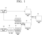
- FIG. 1 is a diagram for describing a method of acquiring a depth image according to an embodiment of the disclosure.
- An electronic device 100 may acquire a first depth image 10 by using a first image sensor 110. Specifically, the electronic device 100 may acquire the first depth image 10 based on a signal output from the first image sensor 110.
- the first depth image 10 is an image indicating a distance from the electronic device 100 to an object, and a depth value (or distance value) of each pixel of the first depth image may refer to a distance from the electronic device 100 to the object corresponding to each pixel.
- the electronic device 100 may acquire a confidence map 20 by using the first image sensor 110.
- the confidence map (or the confidence image) 20 refers to an image representing reliability of depth values for each region of the first depth image 10.
- the confidence map 20 may be an infrared (IR) image corresponding to the first depth image 10.
- the electronic device 100 may determine the reliability of the depth values for each region of the first depth image 10 based on the confidence map 20.
- the electronic device 100 may acquire the confidence map 20 based on a signal output from the first image sensor 110.
- the first image sensor 110 may include a plurality of sensors that are activated from a preset time difference.
- the electronic device 100 may acquire a plurality of image data through each of the plurality of sensors.
- the electronic device 100 may acquire the confidence map 20 from a plurality of acquired image data.
- I1 to I4 denote first to fourth image data, respectively.
- the first image sensor 110 may be implemented as a time of flight (ToF) sensor or a structured light sensor.
- ToF time of flight
- the electronic device 100 may acquire an RGB image 30 using a second image sensor 120. Specifically, the electronic device 100 may acquire the RGB image based on a signal output from the second image sensor 120.
- the RGB image 30 may correspond to the first depth image 10 and the confidence map 20, respectively.
- the RGB image 30 may be an image for the same timing as the first depth image 10 and the confidence map 20.
- the electronic device 100 may acquire the RGB image 30 corresponding to the first depth image 10 and the confidence map 20 by adjusting the activation timing of the first image sensor 110 and the second image sensor 120.
- the electronic device 100 may generate a grayscale image 40 based on R, G, and B values of the RGB image 30.
- the second image sensor 120 may be implemented as image sensors such as a complementary metal-oxide-semiconductor (CMOS) and a charge-coupled device (CCD).
- CMOS complementary metal-oxide-semiconductor
- CCD charge-coupled device
- the electronic device 100 may acquire a second depth image 50 based on the confidence map 20 and the grayscale image 40.
- the electronic device 100 may acquire the second depth image 50 by performing stereo matching on the confidence map 20 and the grayscale image 40.
- the stereo matching refers to a method of calculating a depth value by detecting in which an arbitrary point in one image is located in the other image, and obtaining a shifted amount of the detected result point.
- the electronic device 100 may identify a corresponding point in the confidence map 20 and the grayscale image 40. In this case, the electronic device 100 may identify a corresponding point by identifying a shape or an outline of the object included in the confidence map 20 and the grayscale image 40.
- the electronic device 100 may generate the second depth image 50 based on a disparity between the corresponding points identified in each of the confidence map 20 and the grayscale image 40 and a length (i.e., the distance between the first image sensor 100 and the second image sensor 200) of a baseline.Meanwhile, when the stereo matching may be performed based on the confidence map 20 and the RGB image 30 which are an IR image, it may be difficult to find an exact corresponding point due to a difference in pixel values. Accordingly, the electronic device 100 may perform the stereo matching based on the grayscale image 40 instead of the RGB image 30. Accordingly, the electronic device 100 may more accurately identify the corresponding point, and the accuracy of the depth information included in the second depth image 50 may be improved. Meanwhile, the electronic device 100 may perform pre-processing such as correcting a difference in brightness between the confidence map 20 and the grayscale image 40 before performing the stereo matching.
- the ToF sensor has higher angular resolution (that is, ability to distinguish two objects that are separated from each other) and distance accuracy than the stereo sensor outside a preset distance (e.g., within 5m from the ToF sensor), but may have lower angular resolution and distance accuracy than the stereo sensor within the preset distance.
- angular resolution that is, ability to distinguish two objects that are separated from each other
- distance accuracy than the stereo sensor outside a preset distance (e.g., within 5m from the ToF sensor)
- the electronic device 100 may acquire a third depth image 60 having improved near-field accuracy compared to the first depth image 10 by using the second depth image 50 acquired through the stereo matching.
- the electronic device 100 may acquire the third depth image 60 based on the first depth image 10 and the second depth image 50. Specifically, the electronic device 100 may generate the third depth image 60 by composing the first depth image 10 and the second depth image 50. In this case, the electronic device 100 may determine a first composition ratio ⁇ of the first depth image 10 and a second composition ratio ⁇ of the second depth image 50 based on at least one of the depth value of the first depth image 10 and the pixel value of the confidence map 20.
- the first composition ratio ⁇ and the second composition ratio ⁇ may have a value between 0 and 1, and the sum of the first composition ratio ⁇ and the second composition ratio ⁇ may be 1.
- the second composition ratio ⁇ may be 0.4 (or 400) .
- a method of determining the first composition ratio ⁇ and the second composition ratio ⁇ will be described in more detail.
- FIG. 2 is a graph illustrating a first composition ratio and a second composition ratio according to a depth value of a first depth image according to an embodiment of the disclosure.
- the electronic device 100 may determine the first composition ratio ⁇ and the second composition ratio ⁇ based on a depth value D of the first depth image 10.
- the first composition ratio ⁇ may be determined to be 0, and the second composition ratio ⁇ may be determined to be 1. That is, the electronic device 100 may acquire the depth value of the second depth image 50 as the depth value of the third depth image 60 for a region in which the depth value D is smaller than the first threshold distance Dth1 among the plurality of regions. Accordingly, the electronic device 100 may acquire the third depth image 60 with improved near-field accuracy compared to the first depth image 10.
- a first threshold distance e.g. 20 cm
- the first composition ratio ⁇ may be determined to be 1, and the second composition ratio ⁇ may be determined to be 0. That is, the electronic device 100 may acquire the depth value of the first depth image 50 as the depth value of the third depth image 60 for a region in which the depth value D is greater than the second threshold distance Dth2 among the plurality of regions.
- the first composition ratio ⁇ and the second composition ratio ⁇ may be determined such that, as the depth value D increases, the first composition ratio ⁇ increases and the second composition ratio ⁇ decreases. Since the first image sensor 110 has higher far-field angular resolution than the second image sensor 120, as the depth value D increases, the accuracy of the depth value of the third depth image 60 may be improved when the first composition ratio ⁇ increases.
- the electronic device 100 may determine the first composition ratio ⁇ and the second composition ratio ⁇ based on a pixel value P of the confidence map 20.
- FIG. 3 is a graph illustrating the first composition ratio and the second composition ratio according to the pixel value of the confidence map according to an embodiment of the disclosure.
- the electronic device 100 may identify a fourth region R4 in which the pixel value P is smaller than a first threshold value Pth1 among the plurality of regions of the confidence map 20.
- the electronic device 100 may determine the first composition ratio ⁇ as 0 and the second composition ratio ⁇ as 1. That is, when it is determined that the reliability of the first depth image 10 is smaller than the first threshold value Pth1, the electronic device 100 may acquire the depth value of the second depth image 50 as the depth value of the third depth image 60. Accordingly, the electronic device 100 may acquire the third depth image 60 with improved distance accuracy compared to the first depth image 10.
- the electronic device 100 may identify a fifth region R5 in which the pixel value is greater than a second threshold value Pth2 among the plurality of regions of the confidence map 20.
- the electronic device 100 may determine the first composition ratio ⁇ as 1 and the second composition ratio ⁇ as 0. That is, when it is determined that the reliability of the first depth image 10 is smaller than the second threshold value Pth2, the electronic device 100 may acquire the depth value of the first depth image 10 as the depth value of the third depth image 60.
- the electronic device 100 may identify a sixth region R6 in which the pixel value P is greater than the first threshold value Pth1 and smaller than the second threshold value Pth2 among the plurality of regions of the confidence map 20.
- the electronic device 100 may determine the first composition ratio ⁇ and the second composition ratio ⁇ so that, as the pixel value P increases, the first composition ratio ⁇ increases and the second composition ratio ⁇ decreases. That is, the electronic device 100 may increase the first composition ratio ⁇ as the reliability of the first depth image 10 increases. Accordingly, the accuracy of the depth value of the third depth image 60 may be improved.
- the electronic device 100 may determine the first composition ratio ⁇ and the second composition ratio ⁇ based on the depth value D of the first depth image 10 and the pixel value P of the confidence map 20.
- the electronic device 100 may consider the pixel value P of the confidence map 20 when determining the first composition ratio ⁇ and the second composition ratio ⁇ for the third region R3.
- the electronic device 100 may determine the first composition ratio ⁇ and the second composition ratio ⁇ so that the first composition ratio ⁇ is greater than the second composition ratio ⁇ .
- the electronic device 100 may determine the first composition ratio ⁇ and the second composition ratio ⁇ so that the first composition ratio ⁇ is smaller than the second composition ratio ⁇ .
- the electronic device 100 may increase the first composition ratio ⁇ as the pixel value of the confidence map 20 corresponding to the third region R3 increases. That is, the electronic device 100 may increase the first composition ratio ⁇ for the third region R3 as the reliability of the first depth image 10 increases.
- the electronic device 100 may acquire the third depth image 60 based on the first composition ratio ⁇ and the second composition ratio ⁇ thus obtained.
- the electronic device 100 may acquire the distance information on the object based on the third depth image 60.
- the electronic device 100 may generate a driving path of the electronic device 100 based on the third depth image 60.
- FIGS. 2 and 3 illustrate that the first composition ratio ⁇ and the second composition ratio ⁇ vary linearly, but this is only an example, and the first composition ratio ⁇ and the second composition ratio ⁇ may vary non-linearly.
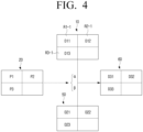
- FIG. 4 is a diagram for describing a method of acquiring a third depth image according to an embodiment of the disclosure.
- the first depth image 10 may include a 1-1th region R1-1, a 2-1th region R2-1, and a 3-1th region R3-1.
- the 1-1th region R1-1 may correspond to the first region R1 of FIG. 2
- the 2-1th region R2-1 may correspond to the second region R2 of FIG. 2 . That is, a depth value D11 of the 1-1th region R1-1 may be smaller than the first threshold distance Dth1, and a depth value D12 of the 2-1th region R2-1 may be greater than the second threshold distance Dth2.
- a 3-1th region R3-1 may correspond to the third region R3 of FIG. 2 . That is, a depth value D13 of the 3-1th region R3-1 may be greater than the first threshold distance Dth1 and smaller than the second threshold distance Dth2.
- the electronic device 100 may determine the first composition ratio ⁇ as 0 and the second composition ratio ⁇ as 1. Accordingly, the electronic device 100 may acquire a depth value D21 of the second depth image 50 as a depth value D31 of the third depth image 60.
- the electronic device 100 may determine the first composition ratio ⁇ as 1 and the second composition ratio ⁇ as 0. Accordingly, the electronic device 100 may acquire the depth value D12 of the first depth image 10 as a depth value D32 of the third depth image 60.
- the electronic device 100 may determine the first composition ratio ⁇ and the second composition ratio ⁇ based on the confidence map 20. For example, if a depth value P3 of the confidence map 20 is smaller than a preset value, when the first depth image 10 and the second depth image 50 are composed for the 3-1th region R3-1, the electronic device 100 may determine the first composition ratio ⁇ and the second composition ratio ⁇ so that the first composition ratio ⁇ is smaller than the second composition ratio ⁇ .
- the electronic device 100 may determine the first composition ratio ⁇ and the second composition ratio ⁇ so that the first composition ratio ⁇ is greater than the second composition ratio ⁇ . As described above, the electronic device 100 may acquire a depth value D33 of the third depth image 60 by applying the first composition ratio ⁇ to the depth value D13 of the first depth image 10, and the second composition ratio ⁇ to a depth value D23 of the second depth image 50.
- the electronic device 100 may acquire the third depth image 60 by applying a predetermined composition ratio to the same object included in the first depth image 10 and the second depth image 50.
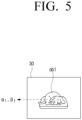
- FIG. 5 is a diagram illustrating an RGB image according to an embodiment of the disclosure.
- the RGB image 30 may include a first object ob1 and a second object ob2.
- the electronic device 100 may analyze the RGB image 30 to identify the first object ob1. In this case, the electronic device 100 may identify the first object ob1 using an object recognition algorithm. Alternatively, the electronic device 100 may identify the first object ob1 by inputting the RGB image 30 to a neural network model trained to identify an object included in the image.
- the electronic device 100 may apply a predetermined composition ratio. For example, the electronic device 100 may apply a 1-1th composition ratio ⁇ 1 and a 2-1th composition ratio ⁇ 1 , which are fixed values, to the region corresponding to the first object ob1. Accordingly, the electronic device 100 may acquire the third depth image 60 in which the distance error for the first object ob1 is improved.
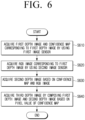
- FIG. 6 is a flowchart illustrating a method for controlling an electronic device according to an embodiment of the disclosure.
- the electronic device 100 may acquire the first depth image and the confidence map corresponding to the first depth image using the first image sensor (S610), and acquire the RGB image corresponding to the first depth image using the second image sensor (S620). As a detailed description thereof has been described with reference to FIG. 1 , a redundant description thereof will be omitted.
- the electronic device 100 may acquire the second depth image based on the confidence map and the RGB image (S630).
- the electronic device 100 may acquire a grayscale image for the RGB image, and acquire the second depth image by performing the stereo matching on the confidence map and the grayscale image.
- the electronic device 100 may acquire the second depth image by performing the stereo matching on the confidence map and the grayscale image based on the shape of the object included in the confidence map and the grayscale image.
- the electronic device 100 may obtain the third depth image by composing the first depth image and the second depth image based on the pixel value of the confidence map (S640).
- the electronic device 100 may determine the composition ratio of the first depth image and the second depth image based on the pixel value of the confidence map, and compose the first depth image and the second depth image based on the determined composition ratio to acquire the third depth image.
- the electronic device 100 may determine the first composition ratio and the second composition ratio so that the first composition ratio of the first depth image is greater than the second composition ratio of the second depth image for the region in which the pixel value is greater than a preset value among the plurality of regions of the confidence map.
- the electronic device 100 may determine the first composition ratio and the second composition ratio so that the first composition ratio is smaller than the second composition ratio for the region in which the pixel value is smaller than a preset value among the plurality of regions of the confidence map.
- FIG. 7 is a perspective view illustrating an electronic device according to an embodiment of the disclosure.
- the electronic device 100 may include the first image sensor 110 and the second image sensor 120.
- the distance between the first image sensor 110 and the second image sensor 120 may be defined as a length L of a baseline.
- the conventional stereo sensor using two cameras has a limitation in that the angular resolution for a long distance is lowered because the length of the baseline is limited.
- the conventional stereo sensor is difficult to miniaturize.
- the electronic device 100 uses the first image sensor 110 having a higher angular resolution for a long distance compared to the stereo sensor as described above, to acquire the far-field information even if the length L of the baseline does not increase. Accordingly, the electronic device 100 may have a technical effect that it is easier to miniaturize compared to the conventional stereo sensor.
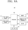
- FIG. 8A is a block diagram illustrating a configuration of the electronic device according to the embodiment of the disclosure.
- the electronic device 100 may include a light emitting unit 105, a first image sensor 110, the second image sensor 120, a memory 130, a communication interface 140, a driving unit 150, and a processor 160.
- the electronic device 100 according to the embodiment of the disclosure may be implemented as a movable robot.
- the light emitting unit 105 may emit light toward an object.
- the light (hereinafter, emitted light) emitted from the light emitting unit 105 may have a waveform in the form of a sinusoidal wave.
- the emitted light may have a waveform in the form of a square wave.
- the light emitting unit 105 may include various types of laser devices.
- the light emitting unit 105 may include a vertical cavity surface emitting laser (VCSEL) or a laser diode (LD).
- the light emitting unit 105 may include a plurality of laser devices. In this case, a plurality of laser devices may be arranged in an array form.
- the light emitting unit 105 may emit light of various frequency bands.
- the light emitting unit 105 may emit a laser beam having a frequency of 100 MHz.
- the first image sensor 110 is configured to acquire the depth image.
- the first image sensor 110 may acquire reflected light reflected from the object after being emitted from the light emitting unit 105.
- the processor 160 may acquire the depth image based on the reflected light acquired by the first image sensor 110.
- the processor 160 may acquire the depth image based on a difference (i.e., flight time of light) between emission timing of the light emitted from the light emitting unit 105 and timing at which the image sensor 110 receives the reflected light.
- the processor 160 may acquire the depth image based on a difference between a phase of the light emitted from the light emitting unit 105 and a phase of the reflected light acquired by the image sensor 110.
- the first image sensor 110 may be implemented as the time of flight (ToF) sensor or the structured light sensor.
- ToF time of flight
- the second image sensor 120 is configured to acquire an RGB image.
- the second image sensor 120 may be implemented as image sensors such as a complementary metal-oxide-semiconductor (CMOS) and a charge-coupled device (CCD) .
- CMOS complementary metal-oxide-semiconductor
- CCD charge-coupled device
- the memory 130 may store an operating system (OS) for controlling a general operation of components of the electronic device 100 and commands or data related to components of the electronic device 100.
- OS operating system
- the memory 130 may be implemented as a non-volatile memory (e.g., a hard disk, a solid state drive (SSD), a flash memory), a volatile memory, or the like.
- the communication interface 140 includes at least one circuit and may communicate with various types of external devices according to various types of communication methods.
- the communication interface 140 may include at least one of a Wi-Fi communication module, a cellular communication module, a 3rd generation (3G) mobile communication module, a 4th generation (4G) mobile communication module, a 4th generation Long Term Evolution (LTE) communication module, and a 5th generation (5G) mobile communication module.
- the electronic device 100 may transmit an image acquired using the second image sensor 120 to a user terminal through the communication interface 140.
- the driving unit 150 is configured to move the electronic device 100.
- the driving unit 150 may include an actuator for driving the electronic device 100.
- the driving unit 150 may include an actuator for driving a motion of another physical component (e.g., an arm, etc.) of the electronic device 100.
- the electronic device 100 may control the driving unit 150 to move or operate based on the depth information obtained through the first image sensor 110 and the second image sensor 120.
- the processor 160 may control the overall operation of the electronic device 100.
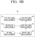
- the processor 160 may include a first depth image acquisition module 161, a confidence map acquisition module 162, an RGB image acquisition module 163, a grayscale image acquisition module 164, a second depth image acquisition module 165, and a third depth image acquisition module 166. Meanwhile, each module of the processor 160 may be implemented as a software module, but may also be implemented in a form in which software and hardware are combined.
- the first depth image acquisition module 161 may acquire the first depth image based on the signal output from the first image sensor 110.
- the first image sensor 110 may include a plurality of sensors that are activated from a preset time difference.
- the first depth image acquisition module 161 may calculate a time of flight of light based on a plurality of image data acquired through a plurality of sensors, and acquire the first depth image based on the calculated time of flight of light.
- the confidence map acquisition module 162 may acquire the confidence map based on the signal output from the first image sensor 110.
- the first image sensor 110 may include a plurality of sensors that are activated from a preset time difference.
- the confidence map acquisition module 162 may acquire a plurality of image data through each of the plurality of sensors.
- the confidence map acquisition module 162 may acquire the confidence map 20 using the plurality of acquired image data.
- the confidence map acquisition module 162 may acquire the confidence map 20 based on [Math Figure 1 ] described above.
- the RGB image acquisition module 163 may acquire the RGB image based on the signal output from the second image sensor 120.
- the acquired RGB image may correspond to the first depth image and the confidence map.
- the grayscale image acquisition module 164 may acquire the grayscale image based on the RGB image acquired by the RGB image acquisition module 163. Specifically, the grayscale image acquisition module 164 may generate the grayscale image based on the R, G, and B values of the RGB image.
- the second depth image acquisition module 165 may acquire the second depth image based on the confidence map acquired by the confidence map acquisition module 162 and the grayscale image acquired by the grayscale image acquisition module 164. Specifically, the second depth image acquisition module 165 may generate the second depth image by performing the stereo matching on the confidence map and the grayscale image. The second depth image acquisition module 165 may identify corresponding points in the confidence map and the grayscale image. In this case, the second depth image acquisition module 165 may identify the corresponding points by identifying the shape or outline of the object included in the confidence map and the grayscale image. In addition, the second depth image acquisition module 165 may generate the second depth image based on the disparity between the corresponding points identified in each of the confidence map and the grayscale image and the length of the baseline.
- the second depth image acquisition module 165 may more accurately identify the corresponding points by performing the stereo matching based on the grayscale image instead of the RGB image. Accordingly, it is possible to improve the accuracy of the depth information included in the second depth image. Meanwhile, the second depth image acquisition module 165 may perform preprocessing such as correcting a difference in brightness between the confidence map and the grayscale image before performing the stereo matching.
- the third depth image acquisition module 166 may acquire the third depth image based on the first depth image and the second depth image.
- the third depth image acquisition module 166 may generate the third depth image by composing the first depth image and the second depth image.
- the third depth image acquisition module 166 may determine the first composition ratio for the first depth image and the second composition ratio for the second depth image based on the depth value of the first depth image.
- the third depth image acquisition module 166 may determine the first composition ratio as 0 and the second composition ratio as 1 for the first region in which the depth value is smaller than the first threshold distance among the plurality of regions of the first depth image.
- the third depth image acquisition module 166 may determine the first composition ratio as 1 and the second composition ratio as 0 for the second region in which the depth value is greater than the second threshold distance among the plurality of regions of the first depth image.
- the third depth image acquisition module 166 may determine the composition ratio based on the pixel value of the confidence map for the third region in which the depth value is greater than the first threshold distance and smaller than the second threshold distance among the plurality of regions of the first depth image. For example, when the pixel value of the confidence map corresponding to the third region is smaller than a preset value, the third depth image acquisition module 166 may determine the first composition ratio and the second composition ratio so that the first composition ratio is smaller than the second composition ratio. When the pixel value of the confidence map corresponding to the third region is larger than a preset value, the third depth image acquisition module 166 may determine the first composition ratio and the second composition ratio so that the first composition ratio is greater than the second composition ratio. That is, the third depth image acquisition module 166 may determine the first composition ratio and the second composition ratio so that the first composition ratio increases and the second composition ratio decreases as the pixel value of the confidence map corresponding to the third region increases.
- the third depth image acquisition module 166 may compose the first depth image and the second depth image with a predetermined composition ratio for the same object.
- the third depth image acquisition module 166 may analyze the RGB image to identify the object included in the RGB image.
- the third depth image acquisition module 166 may apply a predetermined composition ratio to the first region of the first depth image and the second region of the second depth image corresponding to the identified object to compose the first depth image and the second depth image.
- the processor 160 may adjust the sync of the first image sensor 110 and the second image sensor 120. Accordingly, the first depth image, the confidence map, and the second depth image may correspond to each other. That is, the first depth image, the confidence map, and the second depth image may be images for the same timing.
- embodiments described above may be implemented in a computer or an apparatus similar to the computer using software, hardware, or a combination of software and hardware.
- embodiments described in the disclosure may be implemented as a processor itself.
- embodiments such as procedures and functions described in the specification may be implemented as separate software modules. Each of the software modules may perform one or more functions and operations described in the specification.
- computer instructions for performing processing operations according to the diverse embodiments of the disclosure described above may be stored in a non-transitory computer-readable medium.
- the computer instructions stored in the non-transitory computer-readable medium may cause a specific device to perform the processing operations according to the diverse embodiments described above when they are executed by a processor.
- the non-transitory computer-readable medium is not a medium that stores data for a while, such as a register, a cache, a memory, or the like, but means a medium that semi-permanently stores data and is readable by the device.
- Specific examples of the non-transitory computer-readable medium may include a compact disk (CD), a digital versatile disk (DVD), a hard disk, a Blu-ray disk, a USB, a memory card, a read only memory (ROM), and the like.
Landscapes
- Engineering & Computer Science (AREA)
- Physics & Mathematics (AREA)
- General Physics & Mathematics (AREA)
- Theoretical Computer Science (AREA)
- Computer Vision & Pattern Recognition (AREA)
- Electromagnetism (AREA)
- Radar, Positioning & Navigation (AREA)
- Remote Sensing (AREA)
- Computer Networks & Wireless Communication (AREA)
- Optics & Photonics (AREA)
- Multimedia (AREA)
- Image Processing (AREA)
- Measurement Of Optical Distance (AREA)
- Image Analysis (AREA)
Claims (15)
- Ein elektronisches Gerät, das Folgendes umfasst:einen ersten Bildsensor;einen zweiten Bildsensor; undeinen Prozessor,wobei der Prozessor so konfiguriert ist, dass er ein erstes Tiefenbild und eine Konfidenzkarte, die dem ersten Tiefenbild entspricht, unter Verwendung des ersten Bildsensors erfasst, so konfiguriert ist, dass er ein RGB-Bild, das dem ersten Tiefenbild entspricht, unter Verwendung des zweiten Bildsensors erfasst, so konfiguriert ist, dass er ein zweites Tiefenbild auf der Grundlage der Konfidenzkarte und des RGB-Bildes erfasst, und so konfiguriert ist, dass er ein drittes Tiefenbild durch Zusammensetzen des ersten Tiefenbildes und des zweiten Tiefenbildes auf der Grundlage eines Pixelwertes der Konfidenzkarte erfasst.
- Das elektronische Gerät nach Anspruch 1, wobei der Prozessor so konfiguriert ist, dass er ein Graustufenbild für das RGB-Bild erfasst, und
das zweite Tiefenbild durch Ausführen eines Stereoabgleichs an der Konfidenzkarte und dem Graustufenbild gewonnen wird. - Das elektronische Gerät nach Anspruch 2, wobei der Prozessor so konfiguriert ist, dass er das zweite Tiefenbild durch Ausführen eines Stereoabgleichs der Konfidenzkarte und des Graustufenbildes auf der Grundlage einer Form eines in der Konfidenzkarte und dem Graustufenbild enthaltenen Objekts erfasst.
- Das elektronische Gerät nach Anspruch 1, wobei der Prozessor so konfiguriert ist, dass er ein Zusammensetzungsverhältnis des ersten Tiefenbildes und des zweiten Tiefenbildes basierend auf dem Pixelwert der Konfidenzkarte bestimmt und so konfiguriert ist, dass er ein drittes Tiefenbild durch Zusammensetzen des ersten Tiefenbildes und des zweiten Tiefenbildes basierend auf dem bestimmten Zusammensetzungsverhältnis erfasst.
- Das elektronische Gerät nach Anspruch 4, wobei der Prozessor so konfiguriert ist, dass er das erste Zusammensetzungsverhältnis und das zweite Zusammensetzungsverhältnis so bestimmt, dass das erste Zusammensetzungsverhältnis des ersten Tiefenbildes größer ist als das zweite Zusammensetzungsverhältnis des zweiten Tiefenbildes für einen Bereich, in dem ein Pixelwert größer ist als ein voreingestellter Wert unter einer Vielzahl von Bereichen der Konfidenzkarte, und
das erste Zusammensetzungsverhältnis und das zweite Zusammensetzungsverhältnis so bestimmt werden, dass das erste Zusammensetzungsverhältnis kleiner als das zweite Zusammensetzungsverhältnis für den Bereich ist, in dem der Pixelwert kleiner als der voreingestellte Wert unter einer Vielzahl von Bereichen der Konfidenzkarte ist. - Das elektronische Gerät nach Anspruch 1, wobei der Prozessor so konfiguriert ist, dass er einen Tiefenwert des zweiten Tiefenbildes als einen Tiefenwert des dritten Tiefenbildes für einen ersten Bereich erfasst, in dem ein Tiefenwert kleiner als ein erster Schwellenwertabstand unter einer Vielzahl von Bereichen des ersten Tiefenbildes ist, und so konfiguriert ist, dass er einen Tiefenwert des ersten Tiefenbildes als einen Tiefenwert des dritten Tiefenbildes für einen zweiten Bereich erfasst, in dem ein Tiefenwert größer als ein zweiter Schwellenwertabstand unter einer Vielzahl von Bereichen des ersten Tiefenbildes ist.
- Das elektronische Gerät nach Anspruch 1, wobei der Prozessor so konfiguriert ist, dass er ein in dem RGB-Bild enthaltenes Objekt identifiziert, so konfiguriert ist, dass er jeden Bereich des ersten Tiefenbildes und des zweiten Tiefenbildes identifiziert, der dem identifizierten Objekt entspricht, und
so konfiguriert ist, dass er das dritte Tiefenbild durch Zusammensetzen des ersten Tiefenbildes und des zweiten Tiefenbildes mit einem vorbestimmten Zusammensetzungsverhältnis für jeden der Bereiche erfasst. - Das elektronische Gerät nach Anspruch 1, wobei der erste Bildsensor ein Time-of-Flight, ToF, Sensor ist und der zweite Bildsensor ein RGB-Sensor ist.
- Ein Verfahren zur Steuerung eines elektronischen Gerätes, umfassend:Erfassen eines ersten Tiefenbildes und einer Vertrauenskarte, die dem ersten Tiefenbild entspricht, unter Verwendung eines ersten Bildsensors;Erfassen eines RGB-Bildes, das dem ersten Tiefenbild entspricht, unter Verwendung eines zweiten Bildsensors;Erfassen eines zweiten Tiefenbildes auf der Grundlage der Konfidenzkarte und des RGB-Bildes; undErfassen eines dritten Tiefenbildes durch Zusammensetzen des ersten Tiefenbildes und des zweiten Tiefenbildes auf der Grundlage eines Pixelwertes der Konfidenzkarte.
- Das Verfahren nach Anspruch 9, wobei bei der Erfassung des zweiten Tiefenbildes ein Graustufenbild für das RGB-Bild erfasst wird, und
das zweite Tiefenbild durch Stereoabgleich der Konfidenzkarte und des Graustufenbildes gewonnen wird. - Das Verfahren nach Anspruch 10, wobei bei der Erfassung des zweiten Tiefenbildes das zweite Tiefenbild durch Stereoabgleich der Konfidenzkarte und des Graustufenbildes auf der Grundlage einer Form eines in der Konfidenzkarte und dem Graustufenbild enthaltenen Objekts erfasst wird.
- Das Verfahren nach Anspruch 9, wobei bei der Erfassung des dritten Tiefenbildes ein Zusammensetzungsverhältnis des ersten Tiefenbildes und des zweiten Tiefenbildes auf der Grundlage des Pixelwertes der Konfidenzkarte bestimmt wird, und
ein drittes Tiefenbild durch Zusammensetzen des ersten Tiefenbildes und des zweiten Tiefenbildes auf der Grundlage des ermittelten Zusammensetzungsverhältnisses erfasst wird. - Das Verfahren nach Anspruch 12, wobei bei der Bestimmung des Zusammensetzungsverhältnisses das erste Zusammensetzungsverhältnis und das zweite Zusammensetzungsverhältnis so bestimmt werden, dass das erste Zusammensetzungsverhältnis des ersten Tiefenbildes größer ist als das zweite Zusammensetzungsverhältnis des zweiten Tiefenbildes für einen Bereich, in dem ein Pixelwert größer ist als ein voreingestellter Wert unter einer Vielzahl von Bereichen der Konfidenzkarte, und
das erste Zusammensetzungsverhältnis und das zweite Zusammensetzungsverhältnis so bestimmt werden, dass das erste Zusammensetzungsverhältnis kleiner als das zweite Zusammensetzungsverhältnis für den Bereich ist, in dem der Pixelwert kleiner als der voreingestellte Wert unter einer Vielzahl von Bereichen der Konfidenzkarte ist. - Das Verfahren nach Anspruch 9, wobei bei der Erfassung des dritten Tiefenbildes ein Tiefenwert des zweiten Tiefenbildes als Tiefenwert des dritten Tiefenbildes für einen ersten Bereich erfasst wird, in dem ein Tiefenwert kleiner als ein erster Schwellenwertabstand unter einer Vielzahl von Bereichen des ersten Tiefenbildes ist, und
ein Tiefenwert des ersten Tiefenbildes als Tiefenwert des dritten Tiefenbildes für einen zweiten Bereich erfasst wird, in dem ein Tiefenwert größer als ein zweiter Schwellenabstand unter einer Vielzahl von Bereichen des ersten Tiefenbildes ist. - Das Verfahren nach Anspruch 9, wobei das Erfassen des dritten Tiefenbildes Folgendes umfasst,das Identifizieren eines Objekts, das in dem RGB-Bild enthalten ist;das Identifizieren jeden Bereichs des ersten Tiefenbildes und des zweiten Tiefenbildes, die dem identifizierten Objekt entsprechen, unddas Erfassen des dritten Tiefenbildes durch Zusammensetzen des ersten Tiefenbildes und des zweiten Tiefenbildes mit einem vorbestimmten Zusammensetzungsverhältnis für jeden der Bereiche.
Applications Claiming Priority (2)
| Application Number | Priority Date | Filing Date | Title |
|---|---|---|---|
| KR1020200094153A KR20220014495A (ko) | 2020-07-29 | 2020-07-29 | 전자 장치 및 그 제어 방법 |
| PCT/KR2021/008433 WO2022025458A1 (ko) | 2020-07-29 | 2021-07-02 | 전자 장치 및 그 제어 방법 |
Publications (4)
| Publication Number | Publication Date |
|---|---|
| EP4148671A1 EP4148671A1 (de) | 2023-03-15 |
| EP4148671A4 EP4148671A4 (de) | 2024-01-03 |
| EP4148671C0 EP4148671C0 (de) | 2024-08-28 |
| EP4148671B1 true EP4148671B1 (de) | 2024-08-28 |
Family
ID=80035582
Family Applications (1)
| Application Number | Title | Priority Date | Filing Date |
|---|---|---|---|
| EP21850284.7A Active EP4148671B1 (de) | 2020-07-29 | 2021-07-02 | Elektronische vorrichtung und verfahren zur steuerung davon |
Country Status (5)
| Country | Link |
|---|---|
| US (1) | US12456211B2 (de) |
| EP (1) | EP4148671B1 (de) |
| KR (1) | KR20220014495A (de) |
| CN (1) | CN116097306B (de) |
| WO (1) | WO2022025458A1 (de) |
Families Citing this family (6)
| Publication number | Priority date | Publication date | Assignee | Title |
|---|---|---|---|---|
| JP7681405B2 (ja) * | 2021-01-29 | 2025-05-22 | 株式会社小松製作所 | 表示システム及び表示方法 |
| CN114745509B (zh) * | 2022-04-08 | 2024-06-07 | 深圳鹏行智能研究有限公司 | 图像采集方法、设备、足式机器人及存储介质 |
| EP4492810A4 (de) | 2022-05-27 | 2025-06-04 | Samsung Electronics Co., Ltd | Elektronische vorrichtung mit kameramodul und steuerungsverfahren dafür |
| CN115457099B (zh) * | 2022-09-09 | 2023-05-09 | 梅卡曼德(北京)机器人科技有限公司 | 深度补全方法、装置、设备、介质及产品 |
| JP2024175869A (ja) * | 2023-06-07 | 2024-12-19 | キヤノン株式会社 | 検出装置 |
| JP2025158469A (ja) * | 2024-04-04 | 2025-10-17 | オムロン株式会社 | 物体検出装置、物体検出方法、および制御プログラム |
Family Cites Families (28)
| Publication number | Priority date | Publication date | Assignee | Title |
|---|---|---|---|---|
| US20120056982A1 (en) | 2010-09-08 | 2012-03-08 | Microsoft Corporation | Depth camera based on structured light and stereo vision |
| KR101706093B1 (ko) | 2010-11-30 | 2017-02-14 | 삼성전자주식회사 | 3차원 좌표 추출 시스템 및 그 방법 |
| US8401225B2 (en) * | 2011-01-31 | 2013-03-19 | Microsoft Corporation | Moving object segmentation using depth images |
| KR101220527B1 (ko) | 2011-03-02 | 2013-01-21 | 한국과학기술원 | 센서 시스템, 이를 이용하는 환경 지도 작성 시스템 및 방법 |
| KR101272574B1 (ko) * | 2011-11-18 | 2013-06-10 | 재단법인대구경북과학기술원 | 구조광 패턴 기반의 3차원 영상 정보 추정 장치 및 방법 |
| US20140363097A1 (en) * | 2013-06-06 | 2014-12-11 | Etron Technology, Inc. | Image capture system and operation method thereof |
| KR102251483B1 (ko) * | 2014-10-23 | 2021-05-14 | 삼성전자주식회사 | 영상을 처리하는 전자 장치 및 방법 |
| EP3055734A4 (de) | 2014-10-28 | 2016-10-26 | Sz Dji Technology Co Ltd | Rgb-d-bildgebungssystem und -verfahren mithilfe von ultraschalltiefenerfassung |
| KR101714224B1 (ko) * | 2015-09-21 | 2017-03-08 | 현대자동차주식회사 | 센서 융합 기반 3차원 영상 복원 장치 및 방법 |
| US10679326B2 (en) * | 2015-11-24 | 2020-06-09 | Canon Kabushiki Kaisha | Image data processing apparatus and image data processing method that determine confidence data indicating a level of confidence in a pixel value in high resolution image data |
| KR102529120B1 (ko) | 2016-07-15 | 2023-05-08 | 삼성전자주식회사 | 영상을 획득하는 방법, 디바이스 및 기록매체 |
| EP3508814B1 (de) | 2016-09-01 | 2023-08-23 | Sony Semiconductor Solutions Corporation | Bildgebungsvorrichtung |
| US20200162719A1 (en) * | 2017-02-07 | 2020-05-21 | Mindmaze Holding Sa | Systems, methods and apparatuses for stereo vision |
| KR102252915B1 (ko) | 2017-02-22 | 2021-05-18 | 현대자동차주식회사 | 스테레오 카메라를 이용한 거리 추정 방법 및 장치 |
| CN106954058B (zh) * | 2017-03-09 | 2019-05-10 | 深圳奥比中光科技有限公司 | 深度图像获取系统和方法 |
| KR102083293B1 (ko) | 2017-11-15 | 2020-04-23 | 전자부품연구원 | 모션 정보를 이용한 객체 복원 장치 및 이를 이용한 객체 복원 방법 |
| CN109870116B (zh) * | 2017-12-05 | 2021-08-03 | 光宝电子(广州)有限公司 | 深度成像装置及其驱动方法 |
| US10917735B2 (en) * | 2018-05-11 | 2021-02-09 | Facebook Technologies, Llc | Head-related transfer function personalization using simulation |
| CN110852134A (zh) * | 2018-07-27 | 2020-02-28 | 北京市商汤科技开发有限公司 | 活体检测方法、装置及系统、电子设备和存储介质 |
| KR102104031B1 (ko) | 2018-08-16 | 2020-04-24 | 한국항공우주연구원 | 다중센서 융합을 통한 실내 3차원 위치 추정 시스템 및 그 추정 방법 |
| CN111091592B (zh) * | 2018-10-24 | 2023-08-15 | Oppo广东移动通信有限公司 | 图像处理方法、图像处理装置、电子设备及可读存储介质 |
| CN110276767B (zh) * | 2019-06-28 | 2021-08-31 | Oppo广东移动通信有限公司 | 图像处理方法和装置、电子设备、计算机可读存储介质 |
| CN110248096B (zh) * | 2019-06-28 | 2021-03-12 | Oppo广东移动通信有限公司 | 对焦方法和装置、电子设备、计算机可读存储介质 |
| CN112446909B (zh) * | 2019-08-30 | 2022-02-01 | 上海商汤临港智能科技有限公司 | 一种深度图像补全方法及装置、计算机可读存储介质 |
| WO2021051264A1 (zh) * | 2019-09-17 | 2021-03-25 | 深圳市大疆创新科技有限公司 | 基于机器视觉的树木识别方法及装置 |
| WO2021118279A1 (en) | 2019-12-11 | 2021-06-17 | Samsung Electronics Co., Ltd. | Electronic apparatus and method for controlling thereof |
| US11427193B2 (en) * | 2020-01-22 | 2022-08-30 | Nodar Inc. | Methods and systems for providing depth maps with confidence estimates |
| KR102298098B1 (ko) * | 2020-05-29 | 2021-09-03 | 이화여자대학교 산학협력단 | Rgb-d 카메라의 트래킹을 통한 3d 모델의 생성 방법 및 장치 |
-
2020
- 2020-07-29 KR KR1020200094153A patent/KR20220014495A/ko active Pending
-
2021
- 2021-07-02 CN CN202180058359.2A patent/CN116097306B/zh active Active
- 2021-07-02 EP EP21850284.7A patent/EP4148671B1/de active Active
- 2021-07-02 WO PCT/KR2021/008433 patent/WO2022025458A1/ko not_active Ceased
-
2023
- 2023-01-27 US US18/102,527 patent/US12456211B2/en active Active
Also Published As
| Publication number | Publication date |
|---|---|
| KR20220014495A (ko) | 2022-02-07 |
| WO2022025458A1 (ko) | 2022-02-03 |
| CN116097306B (zh) | 2025-10-17 |
| US20230177709A1 (en) | 2023-06-08 |
| EP4148671A1 (de) | 2023-03-15 |
| CN116097306A (zh) | 2023-05-09 |
| EP4148671C0 (de) | 2024-08-28 |
| EP4148671A4 (de) | 2024-01-03 |
| US12456211B2 (en) | 2025-10-28 |
Similar Documents
| Publication | Publication Date | Title |
|---|---|---|
| EP4148671B1 (de) | Elektronische vorrichtung und verfahren zur steuerung davon | |
| CN112106111B (zh) | 一种标定方法、设备、可移动平台及存储介质 | |
| CN103154666B (zh) | 距离测量装置以及环境地图生成装置 | |
| US8446492B2 (en) | Image capturing device, method of searching for occlusion region, and program | |
| US10104359B2 (en) | Disparity value deriving device, movable apparatus, robot, disparity value producing method, and computer program | |
| JP2015143979A (ja) | 画像処理装置、画像処理方法、プログラム、画像処理システム | |
| US11132804B2 (en) | Hybrid depth estimation system | |
| US11921216B2 (en) | Electronic apparatus and method for controlling thereof | |
| US20250076069A1 (en) | Information processing apparatus, information processing method, and storage medium | |
| US20210004978A1 (en) | Method for acquiring depth information of target object and movable platform | |
| US20110043679A1 (en) | Camera device and adjusting method for the same | |
| US20230100249A1 (en) | Information processing device, control method, and non-transitory computer-readable media | |
| JP5803534B2 (ja) | 光通信装置及びプログラム | |
| WO2017090097A1 (ja) | 車両用外界認識装置 | |
| JPH11183142A (ja) | 三次元画像撮像方法及び三次元画像撮像装置 | |
| JP2007233440A (ja) | 車載用画像処理装置 | |
| JP7242822B2 (ja) | 推定システムおよび自動車 | |
| KR102660089B1 (ko) | 객체 깊이 추정 방법 및 장치, 이를 이용한 이동 장치 | |
| US20240233391A9 (en) | Method and device for the detection and determination of the height of objects | |
| Broggi et al. | Handling rolling shutter effects on semi-global matching in automotive scenarios | |
| US20220245766A1 (en) | Image processing device, image processing method, image processing program, and image processing system | |
| KR102191747B1 (ko) | 거리 측정 장치 및 방법 | |
| WO2025104167A1 (en) | Circuitry and method | |
| US20220018658A1 (en) | Measuring system, measuring method, and measuring program | |
| EP4413397A1 (de) | Vorrichtungen und verfahren zur ereignisgeführten tiefenschätzung |
Legal Events
| Date | Code | Title | Description |
|---|---|---|---|
| STAA | Information on the status of an ep patent application or granted ep patent |
Free format text: STATUS: THE INTERNATIONAL PUBLICATION HAS BEEN MADE |
|
| PUAI | Public reference made under article 153(3) epc to a published international application that has entered the european phase |
Free format text: ORIGINAL CODE: 0009012 |
|
| STAA | Information on the status of an ep patent application or granted ep patent |
Free format text: STATUS: REQUEST FOR EXAMINATION WAS MADE |
|
| 17P | Request for examination filed |
Effective date: 20221208 |
|
| AK | Designated contracting states |
Kind code of ref document: A1 Designated state(s): AL AT BE BG CH CY CZ DE DK EE ES FI FR GB GR HR HU IE IS IT LI LT LU LV MC MK MT NL NO PL PT RO RS SE SI SK SM TR |
|
| DAV | Request for validation of the european patent (deleted) | ||
| DAX | Request for extension of the european patent (deleted) | ||
| A4 | Supplementary search report drawn up and despatched |
Effective date: 20231204 |
|
| RIC1 | Information provided on ipc code assigned before grant |
Ipc: G06T 7/521 20170101ALI20231128BHEP Ipc: G06T 7/11 20170101ALI20231128BHEP Ipc: G06T 5/50 20060101ALI20231128BHEP Ipc: G06T 3/40 20060101ALI20231128BHEP Ipc: G06T 7/90 20170101ALI20231128BHEP Ipc: G06T 7/593 20170101AFI20231128BHEP |
|
| GRAP | Despatch of communication of intention to grant a patent |
Free format text: ORIGINAL CODE: EPIDOSNIGR1 |
|
| STAA | Information on the status of an ep patent application or granted ep patent |
Free format text: STATUS: GRANT OF PATENT IS INTENDED |
|
| INTG | Intention to grant announced |
Effective date: 20240415 |
|
| GRAS | Grant fee paid |
Free format text: ORIGINAL CODE: EPIDOSNIGR3 |
|
| GRAA | (expected) grant |
Free format text: ORIGINAL CODE: 0009210 |
|
| STAA | Information on the status of an ep patent application or granted ep patent |
Free format text: STATUS: THE PATENT HAS BEEN GRANTED |
|
| AK | Designated contracting states |
Kind code of ref document: B1 Designated state(s): AL AT BE BG CH CY CZ DE DK EE ES FI FR GB GR HR HU IE IS IT LI LT LU LV MC MK MT NL NO PL PT RO RS SE SI SK SM TR |
|
| REG | Reference to a national code |
Ref country code: CH Ref legal event code: EP |
|
| REG | Reference to a national code |
Ref country code: DE Ref legal event code: R096 Ref document number: 602021018101 Country of ref document: DE |
|
| REG | Reference to a national code |
Ref country code: IE Ref legal event code: FG4D |
|
| U01 | Request for unitary effect filed |
Effective date: 20240902 |
|
| U07 | Unitary effect registered |
Designated state(s): AT BE BG DE DK EE FI FR IT LT LU LV MT NL PT RO SE SI Effective date: 20240916 |
|
| PG25 | Lapsed in a contracting state [announced via postgrant information from national office to epo] |
Ref country code: NO Free format text: LAPSE BECAUSE OF FAILURE TO SUBMIT A TRANSLATION OF THE DESCRIPTION OR TO PAY THE FEE WITHIN THE PRESCRIBED TIME-LIMIT Effective date: 20241128 |
|
| PG25 | Lapsed in a contracting state [announced via postgrant information from national office to epo] |
Ref country code: PL Free format text: LAPSE BECAUSE OF FAILURE TO SUBMIT A TRANSLATION OF THE DESCRIPTION OR TO PAY THE FEE WITHIN THE PRESCRIBED TIME-LIMIT Effective date: 20240828 Ref country code: GR Free format text: LAPSE BECAUSE OF FAILURE TO SUBMIT A TRANSLATION OF THE DESCRIPTION OR TO PAY THE FEE WITHIN THE PRESCRIBED TIME-LIMIT Effective date: 20241129 |
|
| PG25 | Lapsed in a contracting state [announced via postgrant information from national office to epo] |
Ref country code: IS Free format text: LAPSE BECAUSE OF FAILURE TO SUBMIT A TRANSLATION OF THE DESCRIPTION OR TO PAY THE FEE WITHIN THE PRESCRIBED TIME-LIMIT Effective date: 20241228 |
|
| PG25 | Lapsed in a contracting state [announced via postgrant information from national office to epo] |
Ref country code: HR Free format text: LAPSE BECAUSE OF FAILURE TO SUBMIT A TRANSLATION OF THE DESCRIPTION OR TO PAY THE FEE WITHIN THE PRESCRIBED TIME-LIMIT Effective date: 20240828 |
|
| PG25 | Lapsed in a contracting state [announced via postgrant information from national office to epo] |
Ref country code: ES Free format text: LAPSE BECAUSE OF FAILURE TO SUBMIT A TRANSLATION OF THE DESCRIPTION OR TO PAY THE FEE WITHIN THE PRESCRIBED TIME-LIMIT Effective date: 20240828 Ref country code: RS Free format text: LAPSE BECAUSE OF FAILURE TO SUBMIT A TRANSLATION OF THE DESCRIPTION OR TO PAY THE FEE WITHIN THE PRESCRIBED TIME-LIMIT Effective date: 20241128 |
|
| PG25 | Lapsed in a contracting state [announced via postgrant information from national office to epo] |
Ref country code: RS Free format text: LAPSE BECAUSE OF FAILURE TO SUBMIT A TRANSLATION OF THE DESCRIPTION OR TO PAY THE FEE WITHIN THE PRESCRIBED TIME-LIMIT Effective date: 20241128 Ref country code: PL Free format text: LAPSE BECAUSE OF FAILURE TO SUBMIT A TRANSLATION OF THE DESCRIPTION OR TO PAY THE FEE WITHIN THE PRESCRIBED TIME-LIMIT Effective date: 20240828 Ref country code: NO Free format text: LAPSE BECAUSE OF FAILURE TO SUBMIT A TRANSLATION OF THE DESCRIPTION OR TO PAY THE FEE WITHIN THE PRESCRIBED TIME-LIMIT Effective date: 20241128 Ref country code: IS Free format text: LAPSE BECAUSE OF FAILURE TO SUBMIT A TRANSLATION OF THE DESCRIPTION OR TO PAY THE FEE WITHIN THE PRESCRIBED TIME-LIMIT Effective date: 20241228 Ref country code: HR Free format text: LAPSE BECAUSE OF FAILURE TO SUBMIT A TRANSLATION OF THE DESCRIPTION OR TO PAY THE FEE WITHIN THE PRESCRIBED TIME-LIMIT Effective date: 20240828 Ref country code: GR Free format text: LAPSE BECAUSE OF FAILURE TO SUBMIT A TRANSLATION OF THE DESCRIPTION OR TO PAY THE FEE WITHIN THE PRESCRIBED TIME-LIMIT Effective date: 20241129 Ref country code: ES Free format text: LAPSE BECAUSE OF FAILURE TO SUBMIT A TRANSLATION OF THE DESCRIPTION OR TO PAY THE FEE WITHIN THE PRESCRIBED TIME-LIMIT Effective date: 20240828 |
|
| PG25 | Lapsed in a contracting state [announced via postgrant information from national office to epo] |
Ref country code: SM Free format text: LAPSE BECAUSE OF FAILURE TO SUBMIT A TRANSLATION OF THE DESCRIPTION OR TO PAY THE FEE WITHIN THE PRESCRIBED TIME-LIMIT Effective date: 20240828 |
|
| PG25 | Lapsed in a contracting state [announced via postgrant information from national office to epo] |
Ref country code: CZ Free format text: LAPSE BECAUSE OF FAILURE TO SUBMIT A TRANSLATION OF THE DESCRIPTION OR TO PAY THE FEE WITHIN THE PRESCRIBED TIME-LIMIT Effective date: 20240828 |
|
| PG25 | Lapsed in a contracting state [announced via postgrant information from national office to epo] |
Ref country code: SK Free format text: LAPSE BECAUSE OF FAILURE TO SUBMIT A TRANSLATION OF THE DESCRIPTION OR TO PAY THE FEE WITHIN THE PRESCRIBED TIME-LIMIT Effective date: 20240828 |
|
| PLBE | No opposition filed within time limit |
Free format text: ORIGINAL CODE: 0009261 |
|
| STAA | Information on the status of an ep patent application or granted ep patent |
Free format text: STATUS: NO OPPOSITION FILED WITHIN TIME LIMIT |
|
| PGFP | Annual fee paid to national office [announced via postgrant information from national office to epo] |
Ref country code: GB Payment date: 20250624 Year of fee payment: 5 |
|
| 26N | No opposition filed |
Effective date: 20250530 |
|
| U20 | Renewal fee for the european patent with unitary effect paid |
Year of fee payment: 5 Effective date: 20250723 |