EP4148397B1 - Procédés et dispositifs de mesure de débit massique de fluides gazeux - Google Patents
Procédés et dispositifs de mesure de débit massique de fluides gazeux Download PDFInfo
- Publication number
- EP4148397B1 EP4148397B1 EP22195725.1A EP22195725A EP4148397B1 EP 4148397 B1 EP4148397 B1 EP 4148397B1 EP 22195725 A EP22195725 A EP 22195725A EP 4148397 B1 EP4148397 B1 EP 4148397B1
- Authority
- EP
- European Patent Office
- Prior art keywords
- conduit
- flow
- gaseous fluid
- stream
- flowmeter
- Prior art date
- Legal status (The legal status is an assumption and is not a legal conclusion. Google has not performed a legal analysis and makes no representation as to the accuracy of the status listed.)
- Active
Links
Images


Classifications
-
- F—MECHANICAL ENGINEERING; LIGHTING; HEATING; WEAPONS; BLASTING
- F01—MACHINES OR ENGINES IN GENERAL; ENGINE PLANTS IN GENERAL; STEAM ENGINES
- F01D—NON-POSITIVE DISPLACEMENT MACHINES OR ENGINES, e.g. STEAM TURBINES
- F01D17/00—Regulating or controlling by varying flow
- F01D17/02—Arrangement of sensing elements
- F01D17/08—Arrangement of sensing elements responsive to condition of working-fluid, e.g. pressure
-
- G—PHYSICS
- G01—MEASURING; TESTING
- G01F—MEASURING VOLUME, VOLUME FLOW, MASS FLOW OR LIQUID LEVEL; METERING BY VOLUME
- G01F1/00—Measuring the volume flow or mass flow of fluid or fluent solid material wherein the fluid passes through a meter in a continuous flow
- G01F1/56—Measuring the volume flow or mass flow of fluid or fluent solid material wherein the fluid passes through a meter in a continuous flow by using electric or magnetic effects
- G01F1/58—Measuring the volume flow or mass flow of fluid or fluent solid material wherein the fluid passes through a meter in a continuous flow by using electric or magnetic effects by electromagnetic flowmeters
- G01F1/582—Measuring the volume flow or mass flow of fluid or fluent solid material wherein the fluid passes through a meter in a continuous flow by using electric or magnetic effects by electromagnetic flowmeters without electrodes
-
- B—PERFORMING OPERATIONS; TRANSPORTING
- B64—AIRCRAFT; AVIATION; COSMONAUTICS
- B64D—EQUIPMENT FOR FITTING IN OR TO AIRCRAFT; FLIGHT SUITS; PARACHUTES; ARRANGEMENT OR MOUNTING OF POWER PLANTS OR PROPULSION TRANSMISSIONS IN AIRCRAFT
- B64D37/00—Arrangements in connection with fuel supply for power plant
- B64D37/005—Accessories not provided for in the groups B64D37/02 - B64D37/28
-
- B—PERFORMING OPERATIONS; TRANSPORTING
- B64—AIRCRAFT; AVIATION; COSMONAUTICS
- B64D—EQUIPMENT FOR FITTING IN OR TO AIRCRAFT; FLIGHT SUITS; PARACHUTES; ARRANGEMENT OR MOUNTING OF POWER PLANTS OR PROPULSION TRANSMISSIONS IN AIRCRAFT
- B64D37/00—Arrangements in connection with fuel supply for power plant
- B64D37/30—Fuel systems for specific fuels
-
- G—PHYSICS
- G01—MEASURING; TESTING
- G01F—MEASURING VOLUME, VOLUME FLOW, MASS FLOW OR LIQUID LEVEL; METERING BY VOLUME
- G01F1/00—Measuring the volume flow or mass flow of fluid or fluent solid material wherein the fluid passes through a meter in a continuous flow
- G01F1/56—Measuring the volume flow or mass flow of fluid or fluent solid material wherein the fluid passes through a meter in a continuous flow by using electric or magnetic effects
- G01F1/58—Measuring the volume flow or mass flow of fluid or fluent solid material wherein the fluid passes through a meter in a continuous flow by using electric or magnetic effects by electromagnetic flowmeters
- G01F1/60—Circuits therefor
-
- G—PHYSICS
- G01—MEASURING; TESTING
- G01F—MEASURING VOLUME, VOLUME FLOW, MASS FLOW OR LIQUID LEVEL; METERING BY VOLUME
- G01F1/00—Measuring the volume flow or mass flow of fluid or fluent solid material wherein the fluid passes through a meter in a continuous flow
- G01F1/76—Devices for measuring mass flow of a fluid or a fluent solid material
-
- B—PERFORMING OPERATIONS; TRANSPORTING
- B64—AIRCRAFT; AVIATION; COSMONAUTICS
- B64D—EQUIPMENT FOR FITTING IN OR TO AIRCRAFT; FLIGHT SUITS; PARACHUTES; ARRANGEMENT OR MOUNTING OF POWER PLANTS OR PROPULSION TRANSMISSIONS IN AIRCRAFT
- B64D41/00—Power installations for auxiliary purposes
- B64D2041/005—Fuel cells
Definitions
- the disclosure relates generally to flowmeters and, more particularly, to flowmeters for gaseous fluids.
- Aircraft engines may be provided with various flowmeters to measure the flow rate of the various fluids used in the engine.
- Various types of flowmeters exist, such as flowmeters based on hydrodynamic methods, flowmeters with continuously moving bodies, and flowmeters based on various physical phenomena.
- flowmeters based on certain physical phenomena may be limited to measuring the flow rate of liquids.
- alternative fuels such as hydrogen in gas turbine engines can pose certain design/engineering challenges, which are not encountered when jet fuels are used.
- certain alternative fuels such as hydrogen
- any on-board flowmeters for measuring the mass flow of the aircraft's fuel must be capable of measuring the flow rate of gaseous fluids. As such, improvements are desired.
- DE 10 2018 116 918 A1 discloses a prior art fluidic detection system for the magnetic-electrical measurement of a fluid sample, wherein the system comprises at least one sample module, one magnetic field sensor, and one magnet, which are spaced apart from one another.
- the sample module has at least one channel which is designed for transporting a fluid sample along a flow direction.
- the magnet generates a magnetic field in a measurement and excitation region of the channel.
- the detection region of the magnetic field sensor corresponds to the measurement and excitation region of the channel.
- a flowmeter for gaseous fluid as set forth in claim 1.
- the flowmeter further comprises an ionizer for ionizing the gaseous fluid to produce the ionized flow.
- the ionizer is configured for stripping away electrons from gas molecules in the gaseous fluid and the ionized flow is positively charged.
- the ionizer is configured for adding electrons to gas molecules in the gaseous fluid and the ionized flow is negatively charged.
- the electromagnetic sensor comprises any one of a Hall effect sensor, an anisotropic magneto-resistive sensor, a giant magnetoresistance sensor, and a transformer.
- the flowmeter further comprises a flow divider upstream from the conduit for separating the gaseous fluid into a first stream and a second stream, wherein the first stream flows through the conduit and the second stream flows externally to the conduit, and a flow combiner downstream from the conduit for recombining the first stream and the second stream together.
- the flowmeter further comprises a flow modulator upstream from the electromagnetic sensor to pulse the gaseous fluid and produce an alternating current in the conduit.
- the flowmeter further comprises a measuring circuit coupled to the electromagnetic sensor for receipt of the signal generated by the electromagnetic sensor and conversion of the signal to a mass flow of the gaseous fluid.
- the method further comprises ionizing the gaseous fluid to produce the ionized flow.
- the method further comprises separating the gaseous fluid into a first stream and a second stream, wherein the first stream flows through the conduit and the second stream flows externally to the conduit, and recombining the first stream and the second stream together after the measuring of the magnetic field.
- the method further comprises pulsing the gaseous fluid to produce an alternating current in the conduit.
- the present disclosure is directed to measuring the mass flow of gaseous fluids, for example as used in a hydrogen fuel cell.
- the properties of gaseous fluids differ from the properties of liquids.
- gaseous fluids are compressible whereas liquids are not.
- the compressibility of gaseous fluids makes it difficult to measure its mass flow using traditional flowmeters suitable for liquids. Therefore, there are described herein methods, systems and devices for measuring gaseous fluids.
- the gaseous fluid is gaseous fuel used by an engine.
- gaseous fuel refers to fuels that exist in the gaseous state at room temperature. Examples of gaseous fuels are hydrogen gas, natural gas, butane and propane.
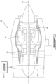
- FIG. 1 illustrates an example engine 100 of a type provided for use in subsonic flight, generally comprising in serial flow communication a fan 12 through which ambient air is propelled, a compressor section 14 for pressurizing the air, a combustor 16 in which the compressed air is mixed with fuel and ignited for generating an annular stream of hot combustion gases, and a turbine section 18 for extracting energy from the combustion gases.
- a longitudinal main engine axis 11 extends through the center of the engine 100.
- turbofan engine 100 is shown in Fig. 1 for exemplary purposes, it is to be understood that the engine 100 as described herein may alternately be another type of gas turbine engine, including for example turboshafts, turboprops, and turbojets, or another type of combustion engine, such as a Wankel engine or a reciprocating engine.
- the expression "combustor" should be understood to include any chamber within an engine in which combustion can occur.
- the engine 100 forms part of an aircraft.
- the engine 100 forms part of a vehicle for land or marine applications.
- the engine 100 is used in an industrial setting, for example for power generation or as an auxiliary power unit.
- Engine 100 may be powered in part or entirely by gaseous fuel.
- Engine 100 may also be a hybrid or bi-fuel propulsion system, in which two different fuel types (e.g. an alternative fuel such as hydrogen, as well as a traditional jet fuel) may be used.
- two different fuel types e.g. an alternative fuel such as hydrogen, as well as a traditional jet fuel
- Control of the operation of the engine 100 can be effected by one or more control systems, for example a controller 110, which is communicatively coupled to the engine 100.
- the operation of the engine 100 can be controlled by way of one or more actuators, mechanical linkages, hydraulic systems, and the like.
- the controller 110 can be coupled to the actuators, mechanical linkages, hydraulic systems, and the like, in any suitable fashion for effecting control of the engine 100.
- the controller 110 can modulate the position and orientation of variable geometry mechanisms within the engine 100, the bleed level of the engine 100, and fuel flow, based on predetermined schedules or algorithms.
- the controller 110 can be implemented as part of a full-authority digital engine controls (FADEC) or other similar device, including electronic engine control (EEC), engine control unit (ECU), electronic propeller control, propeller control unit, and the like.
- FADEC full-authority digital engine controls
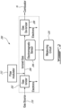
- flowmeter 200 for measuring the mass flow rate of a gaseous fluid.
- the flowmeter 200 measures gas flow in a manner similar to the external measurement of electric current, where charged particles (i.e. electrons) move in a fixed space and result in a magnetic field surrounding a conductor. This principle is reproduced in gas particles by the flowmeter 200, whereby a charged gas flows through a non-electrically conductive conduit 204 and an electromagnetic sensor 206 measures a resulting magnetic field.
- flowmeter 200 is configured for measuring the flow rate of gaseous fuel used in engine 100.
- the flowmeter 200 may be positioned upstream of combustor 16. Alternatively, the flowmeter 200 may be positioned elsewhere in the engine 100.
- the non-electrically conductive material may be, for example, an insulative material or a non-insulative material that is non-electrically conductive such as a semi-conductor material.
- the gaseous fluid is provided to a gas ionizer 202 from a gas source 210.
- the gas source 210 may be the engine's primary fuel tank. In other embodiments, the gas source 210 may be another source for the gas whose flow is to be measured.
- gas particles from the gas source 210 are sent to the gas ionizer 202 to impart a positive or negative charge to the gas, producing a charged gas (i.e. a plasma). If the gaseous fluid is already ionized, the gas ionizer 202 may be omitted.
- the positively or negatively charged gas is then directed through the conduit 204, where the electromagnetic sensor 206 is arranged to measure the magnetic field generated about the conduit by the passage of the ionized flow and to generate a signal, such as voltage or current, proportional to the magnetic field.
- the generated signal may then be used to determine the mass flow of the gas via a measuring circuit 220. In some cases, the measuring circuit 220 may be omitted, whereby the output of the flow meter is the signal generated by the electromagnetic sensor 206.
- the charged gas is sent to a de-ionizer 208 for neutralization after the magnetic field has been measured.
- gas ionizers 202 may be contemplated to ionize the gas molecules, utilizing methods such as electric discharge, laser ionization, or the application of very high electric or magnetic fields.
- electrons may be stripped away from the gas molecules, resulting in positively charged ions.
- electrons may be added to the gas molecules, resulting in positively charged ions.
- energy must be provided to either add or remove one or more electron from each gas particle, resulting in electrically charged gas particles, also referred to as gas ions or plasma.
- Power is supplied to the gas ionizer 202 in order to ionize the gas particle, for instance from a battery or other power source within engine 100.
- the power source may be dedicated to the flowmeter 200 or shared, for example a battery from a hybrid engine.
- the quantity of power required may depend on factors such as the type and quantity of gas being ionized.
- the electromagnetic sensor 206 may be a Hall effect sensor, an anisotropic magneto-resistive (AMR) sensor, a giant magnetoresistance (GMR) sensor, or a transformer.
- the flowmeter 200 may further include a flow modulator 212 upstream from the electromagnetic sensor 206 to pulse the gaseous fluid and produce the alternating current in the conduit 204.
- Other devices capable of measuring the magnitude of the magnetic field generated by the flow of ions through the conduit 204 and, in response, produce a proportional signal may be contemplated as well.
- the conduit 204 is made of a non-electrically conductive material.
- the gas de-ionizer 208 also referred to as a gas neutralizer, is operable to de-ionizer or neutralize the ionized gas after it has passed through the conduit 204 and the generated magnetic field is measured.
- a gas neutralizer operable to de-ionizer or neutralize the ionized gas after it has passed through the conduit 204 and the generated magnetic field is measured.
- Various means for neutralizing the gas i.e. adding electrons to the positively charged plasma or removing electrons from the negatively charged plasma, may be contemplated.
- the measurement circuit 220 is coupled to the electromagnetic sensor for receipt of the voltage generated by electromagnetic sensor 206 and conversion of this voltage to a mass flow of the ionized gaseous fluid flowing through the conduit 204.
- the mass flow rate of the gas is directly proportional to the outputted signal from the electromagnetic sensor 206, which itself is proportional to the magnitude of the magnetic field generated by the flow of ions through the conduit 204.
- various scale factors or ratios may be used to calculate the mass flow of the gas from the outputted signal.
- Y is the mass flow
- X is the measured parameter (in millivolts, volts, amps, milliamps, etc)
- M is a scale factor
- B is an offset.
- Any electronic component suitable for converting a measured signal to mass flow may be used, such as but not limited to a microcontroller, a field programmable gate array (FPGA), a complex programmable logic device (CPLD), and a field programmable analog array (FPAA).
- the measuring circuit 220 is integrated into the engine controller 110.
- the engine controller 110 may be configured to control the flow of the gaseous fuel based on the mass flow as measured by the flowmeter 200.
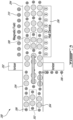
- gaseous hydrogen molecules 302 are directed through conduit 204 of flowmeter 200.
- Each hydrogen molecule 302, commonly referred to as H 2 emanating from the gas source 210 includes two positively charged protons 304 and two negatively charged electrons 306.
- the size of each hydrogen molecule 302 relative to the conduit 204 is highly exaggerated.
- power is supplied to the gas ionizer 202 and an electron 306 is stripped or removed from each hydrogen molecule 302, resulting in a plurality of positively charged hydrogen ions 308, also referred to as dihydrogen cations or hydrogen molecular ions (H 2 + ).
- Each hydrogen ion 308 includes two protons 304 and a single electron 306, resulting in an overall positive charge.
- the flow of hydrogen ions 308 through the conduit 204 creates a magnetic field 310 in the area around the conduit 204, which can be detected and measured by the electromagnetic sensor 206 (illustratively a Hall effect sensor).
- each molecule requires a certain amount of energy (i.e. ionization energy) to add or remove an electron from it.
- the measured ionization energy of H 2 is 1488 kJ/mol.
- the gas ionizer 202 must be set to a high enough level to saturate (i.e. add or strip electron(s) from each molecule) at the highest possible flow rate of the gas through conduit 204 to ensure that all of the gas molecules have been ionized. This will ensure the accuracy of the flowmeter 200, as unionized gas molecules will not generate a magnetic field 310 and thus not be accounted for by the electromagnetic sensor 206.
- the power level applied to the gas ionizer 202 may be adjusted, for instance, based on the type of fluid and the expected flow rate.
- the flowmeter 200 may be operable to measure a diverted portion of the gas by separating the gas flow into a main gas path 400 and a secondary gas path 404. For instance, if a substantial amount of power is needed to ionize an entire flow of gas in order to measure its mass flow via flowmeter 200, a portion of the gas glow may be separated and recombined for the purpose of flow measurement. A calculated ratio between the diverted gas flow and the undiverted gas flow may be used to estimate the mass flow of the entire gas flow..
- a flow divider 402 may split the gas into two streams: a first stream towards the flowmeter 200 via the secondary gas path 404 and a second stream continuing through the main gas path 400.
- the quantity of gas diverted through the secondary gas path 404 relative to the quantity of gas remaining in the main gas path 400 is used to estimate the mass flow of the entire gas flow.
- the flow divider 402 may include a pair of orifices, a first orifice with a larger surface area diverting gas towards the main gas path 400 and a second orifice with a smaller surface area diverting gas towards the flowmeter 200 via the secondary gas path 404.
- a ratio may be determined via the relative areas of the orifices.
- a ratio may be determined based on their relative diameters.
- the mass flow determined via the measuring circuit 220 may take into account the ratio of gas in the main gas path 400 vs gas in the secondary gas path 404 to calculate the mass flow of the entire flow of gas.
- an exemplary method 500 for measuring mass flow of a gaseous fluid may be performed to measure mass flow of gaseous fuel, such as for an engine, or to measure mass flow of any other gaseous fluid.
- the gaseous fluid is ionized to produce an ionized flow.
- the gaseous fluid may be gaseous hydrogen (H 2 ) acting as a fuel source for engine 100, and the gaseous fluid may be ionized by gas ionizer 202. Ionizing the gaseous fluid may be performed by adding or removing electrons to obtain a charged or ionized flow of gaseous fluid. If the flow is already ionized, step 502 may be omitted.
- the ionized flow of gaseous fluid is received in a non-electrically conductive conduit 204.
- Any non-electrically conductive material may be used for the conduit 204, such as fiberglass, rubber, plastics, and the like. It will be understood that the gaseous fluid may be ionized prior to receipt inside the conduit, concurrently with receipt into the conduit, or after receipt into the conduit. As such, the order of steps 502 and 504 is interchangeable.
- only a portion of the conduit 204 is made of non-electrically conductive material and receipt therein comprises receipt in the portion of the conduit made of non-electrically conductive material.
- a magnetic field 310 generated about the non-electrically conductive conduit 204 by the ionized flow is measured by the electromagnetic sensor 206, which may be for instance, one or more of a Hall effect sensor, an anisotropic magneto-resistive (AMR) sensor, a giant magnetoresistance (GMR) sensor, a transformer, induction coils, a magnetoimpedance (MI) sensor, a fluxgate sensor, an optical magnet sensor, an atomic magnetometer, and a superconducting quantum interference device (SQUID). Any sensor capable of detecting changes and disturbances in a magnetic field like flux, strength and direction may be used. In some embodiments, a combination of sensors of same or different types are used. A signal, such as voltage or current, proportional to the magnetic field is then generated by the electromagnetic sensor 206.
- the signal generated by the electromagnetic sensor 206 proportional to the magnetic field is converted to the mass flow of the gaseous fluid by the measuring circuit 220.
- the measuring circuit 220 forms part of the engine controller 110. In some embodiments, the measuring circuit is external to the engine controller 110 and communicatively coupled thereto.
- the ionized flow is neutralized by gas de-ionizer 208, by either adding or removing electron(s) to the charged gas.
- the flowmeter 200 is operable to measure the flow rate of a gaseous fluid without the use of dynamic components that are susceptible to the harsh realities that aerospace engines are subjected to, such as vibrations and severe thermal variations.
- the flowmeter 200 described herein does not require any components positioned in the flow of the gaseous fluid itself which may impact the momentum of the flow and delay the response times.
- the ionizer 202, de-ionizer 208, and electromagnetic sensor 206 may all be provided externally to the conduit 204.
- the measuring circuit 220 is implemented in a computing device 600, an example of which is illustrated in Fig. 6 .
- the measuring circuit 220 may include more computing devices 600 operable to exchange data.
- the computing devices 600 may be the same or different types of devices.
- the controller 110 may be implemented with one or more computing devices 600.
- the computing device 600 comprises a processing unit 602 and a memory 604 which has stored therein computer-executable instructions 606.
- the processing unit 602 may comprise any suitable devices configured to convert a given parameter such as voltage or current into mass flow.
- the processing unit 602 may comprise, for example, any type of general-purpose microprocessor or microcontroller, a digital signal processing (DSP) processor, a central processing unit (CPU), an integrated circuit, a field programmable gate array (FPGA), a reconfigurable processor, other suitably programmed or programmable logic circuits, or any combination thereof.
- DSP digital signal processing
- CPU central processing unit
- FPGA field programmable gate array
- reconfigurable processor other suitably programmed or programmable logic circuits, or any combination thereof.
- the memory 604 may comprise any suitable known or other machine-readable storage medium.
- the memory 604 may comprise non-transitory computer readable storage medium, for example, but not limited to, an electronic, magnetic, optical, electromagnetic, infrared, or semiconductor system, apparatus, or device, or any suitable combination of the foregoing.
- the memory 604 may include a suitable combination of any type of computer memory that is located either internally or externally to the device, for example random-access memory (RAM), read-only memory (ROM), compact disc read-only memory (CDROM), electro-optical memory, magnetooptical memory, erasable programmable read-only memory (EPROM), and electrically-erasable programmable read-only memory (EEPROM), Ferroelectric RAM (FRAM) or the like.
- Memory 604 may comprise any storage means (e.g., devices) suitable for retrievably storing machine-readable instructions 606 executable by processing unit 602.
- Computer-executable instructions 606 may be in many forms, including program modules, executed by one or more computers or other devices.
- program modules include routines, programs, objects, components, data structures, etc., that perform particular tasks or implement particular abstract data types.
- functionality of the program modules may be combined or distributed as desired in various embodiments.
- the embodiments described herein are implemented by physical computer hardware, including computing devices, servers, receivers, transmitters, processors, memory, displays, and networks.
- the embodiments described herein provide useful physical machines and particularly configured computer hardware arrangements.
- the embodiments described herein are directed to electronic machines and methods implemented by electronic machines adapted for processing and transforming electromagnetic signals which represent various types of information.
- the embodiments described herein pervasively and integrally relate to machines, and their uses; and the embodiments described herein have no meaning or practical applicability outside their use with computer hardware, machines, and various hardware components. Substituting the physical hardware particularly configured to implement various acts for non-physical hardware, using mental steps for example, may substantially affect the way the embodiments work.
- connection or “coupled to” may include both direct coupling (in which two elements that are coupled to each other contact each other) and indirect coupling (in which at least one additional element is located between the two elements).
- the technical solution of embodiments may be in the form of a software product.
- the software product may be stored in a non-volatile or non-transitory storage medium, which can be a compact disk read-only memory (CD-ROM), a USB flash disk, or a removable hard disk.
- the software product includes a number of instructions that enable a computer device (personal computer, server, or network device) to execute the methods provided by the embodiments.
Landscapes
- Physics & Mathematics (AREA)
- Fluid Mechanics (AREA)
- General Physics & Mathematics (AREA)
- Engineering & Computer Science (AREA)
- Electromagnetism (AREA)
- Aviation & Aerospace Engineering (AREA)
- Mechanical Engineering (AREA)
- General Engineering & Computer Science (AREA)
- Measuring Volume Flow (AREA)
Claims (12)
- Débitmètre (200) pour fluide gazeux comprenant :un conduit (204) composé d'un matériau non conducteur d'électricité pour le passage d'un flux ionisé du fluide gazeux à travers celui-ci ;un capteur électromagnétique (206) agencé pour mesurer un champ magnétique généré autour du conduit (204) par le passage du flux ionisé et générer un signal proportionnel au champ magnétique ;et caractérisé parun déioniseur (208) destiné à neutraliser le flux ionisé en aval du capteur électromagnétique (206).
- Débitmètre (200) selon la revendication 1, comprenant également un ioniseur (202) destiné à ioniser le fluide gazeux pour produire le flux ionisé.
- Débitmètre (200) selon la revendication 2, dans lequel l'ioniseur (202) est configuré pour extraire des électrons des molécules de gaz dans le fluide gazeux et le flux ionisé est chargé positivement.
- Débitmètre (200) selon la revendication 2, dans lequel l'ioniseur (202) est configuré pour ajouter des électrons aux molécules de gaz dans le fluide gazeux et le flux ionisé est chargé négativement.
- Débitmètre (200) selon l'une quelconque des revendications 1 à 4, dans lequel le capteur électromagnétique (206) comprend l'un quelconque d'un capteur à effet Hall, d'un capteur magnétorésistif anisotrope, d'un capteur à magnétorésistance géante et d'un transformateur.
- Débitmètre (200) selon l'une quelconque des revendications 1 à 5, comprenant également :un diviseur de débit (402) en amont du conduit (204) destiné à séparer le fluide gazeux en un premier flux et un second flux, dans lequel le premier flux s'écoule à travers le conduit (204) et le second flux s'écoule à l'extérieur du conduit (204) ; etun combinateur de débit (408) en aval du conduit (204) destiné à recombiner le premier flux et le second flux.
- Débitmètre (200) selon l'une quelconque des revendications 1 à 6, comprenant également :
un modulateur de débit (212) en amont du capteur électromagnétique (206) pour pulser le fluide gazeux et produire un courant alternatif dans le conduit (204). - Débitmètre (200) selon l'une quelconque des revendications 1 à 7, comprenant également un circuit de mesure (220) couplé au capteur électromagnétique (206) pour la réception du signal généré par le capteur électromagnétique (206) et la conversion du signal en un débit massique du fluide gazeux.
- Procédé de mesure du débit massique d'un fluide gazeux, le procédé comprenant :la réception d'un flux ionisé du fluide gazeux dans un conduit non conducteur d'électricité (204) ;la mesure d'un champ magnétique généré autour du conduit (204) par le flux ionisé et la génération d'un signal proportionnel au champ magnétique ;la conversion du signal proportionnel au champ magnétique en un débit massique du fluide gazeux ; et caractérisé par la neutralisation du flux ionisé après la mesure du champ magnétique.
- Procédé selon la revendication 9, comprenant également l'ionisation du fluide gazeux pour produire le flux ionisé.
- Procédé selon la revendication 9 ou 10, comprenant également :la séparation du fluide gazeux en un premier flux et un second flux, dans lequel le premier flux s'écoule à travers le conduit (204) et le second flux s'écoule à l'extérieur du conduit (204) ; etla recombinaison du premier flux et du second flux après la mesure du champ magnétique.
- Procédé selon l'une quelconque des revendications 9 à 11, comprenant également la pulsation du fluide gazeux pour produire un courant alternatif dans le conduit (204).
Applications Claiming Priority (1)
| Application Number | Priority Date | Filing Date | Title |
|---|---|---|---|
| US17/474,548 US12085428B2 (en) | 2021-09-14 | 2021-09-14 | Methods and devices for measuring mass flow of gaseous fluids |
Publications (2)
| Publication Number | Publication Date |
|---|---|
| EP4148397A1 EP4148397A1 (fr) | 2023-03-15 |
| EP4148397B1 true EP4148397B1 (fr) | 2025-06-25 |
Family
ID=83318769
Family Applications (1)
| Application Number | Title | Priority Date | Filing Date |
|---|---|---|---|
| EP22195725.1A Active EP4148397B1 (fr) | 2021-09-14 | 2022-09-14 | Procédés et dispositifs de mesure de débit massique de fluides gazeux |
Country Status (3)
| Country | Link |
|---|---|
| US (1) | US12085428B2 (fr) |
| EP (1) | EP4148397B1 (fr) |
| CA (1) | CA3171065A1 (fr) |
Family Cites Families (11)
| Publication number | Priority date | Publication date | Assignee | Title |
|---|---|---|---|---|
| US2149847A (en) * | 1937-07-15 | 1939-03-07 | Kolin Alexander | Apparatus for measuring fluid flow |
| US3842670A (en) | 1969-03-28 | 1974-10-22 | Nat Res Dev | Improvements in measuring the velocity of gases |
| US4152935A (en) | 1978-01-12 | 1979-05-08 | Nissan Motor Company, Limited | Mass flow measuring apparatus |
| FR2467404A1 (fr) | 1979-10-10 | 1981-04-17 | Renault | Capteur de mesure de la vitesse d'un gaz a ionisation |
| SU1636775A1 (ru) | 1988-05-27 | 1991-03-23 | Научно-производственное объединение "ЭНЕРГИЯ" | Способ определени электропроводности и скорости потока ионизированного газа и устройство дл его осуществлени |
| GB9205190D0 (en) * | 1992-03-10 | 1992-04-22 | Univ Sheffield | Flow circuit for a flow meter |
| DE10322550A1 (de) | 2003-05-20 | 2004-12-30 | Abb Patent Gmbh | Verfahren zum Betrieb einer Durchflussmesseinrichtung, sowie Durchflussmesseinrichtung selbst |
| PL1960743T3 (pl) | 2005-12-13 | 2017-06-30 | Sentec Limited | Licznik gazu |
| US20090166555A1 (en) | 2007-12-28 | 2009-07-02 | Olson Joseph C | RF electron source for ionizing gas clusters |
| FR3060125B1 (fr) | 2016-12-08 | 2018-12-07 | Office National D'etudes Et De Recherches Aerospatiales | Dispositif et procede de mesure d'une vitesse d'ecoulement de gaz |
| DE102018116918A1 (de) | 2018-07-12 | 2020-01-16 | Helmholtz-Zentrum Dresden - Rossendorf E.V. | Fluidik-Detektionssystem |
-
2021
- 2021-09-14 US US17/474,548 patent/US12085428B2/en active Active
-
2022
- 2022-08-24 CA CA3171065A patent/CA3171065A1/fr active Pending
- 2022-09-14 EP EP22195725.1A patent/EP4148397B1/fr active Active
Also Published As
| Publication number | Publication date |
|---|---|
| CA3171065A1 (fr) | 2023-03-14 |
| US20230078572A1 (en) | 2023-03-16 |
| EP4148397A1 (fr) | 2023-03-15 |
| US12085428B2 (en) | 2024-09-10 |
Similar Documents
| Publication | Publication Date | Title |
|---|---|---|
| Bityurin et al. | Assessment of a concept of advanced flow/flight control for hypersonic flights in atmosphere | |
| Conversano et al. | Magnetically shielded miniature Hall thruster: performance assessment and status update | |
| Coral et al. | Microwave power absorption to high energy electrons in the ECR ion thruster | |
| EP4148397B1 (fr) | Procédés et dispositifs de mesure de débit massique de fluides gazeux | |
| Bityurin et al. | Results of experiments on MHD hypersonic flow control | |
| Yagodnikov et al. | Diagnostics of rocket and jet engines through characteristics of the intrinsic electromagnetic field of combustion products | |
| Bityurin et al. | Study of MHD interaction in hypersonic flows | |
| Sheikin et al. | Scramjet with MHD bypass under" AJAX" concept | |
| Kava et al. | Numerical simulation of electron-beam powered plasma fueled engines | |
| Macheret et al. | Magnetohydrodynamic and electrohydrodynamic control of hypersonic flows of weakly ionized plasmas | |
| Gotoh et al. | Computational analysis of HVEPS scramjet MHD power generation | |
| Golovachov et al. | Numerical simulation of MGD flows in supersonic inlets | |
| Xu et al. | Direct Numerical Simulation of Low Rem Compressible Magnetohydrodynamic Isotropic Turbulence | |
| Chavers et al. | Status of magnetic nozzle and plasma detachment experiment | |
| Bityurin | A feasibility study and experimental evaluation on MHD acceleration for application to advanced propulsion and hypervelocity ground testing | |
| Vavilov et al. | Determination of the parameters of the microwave ion thruster by the calorimetric method | |
| Byrne et al. | Coupling of electrical and pressure facility effects in Hall effect thruster testing | |
| Kim et al. | A numerical model of a back powered channel for MHD generator application | |
| Merkle et al. | Computational simulations of power extraction in MHD channel | |
| Sweeney | Fundamental investigations of ion-sensing in gas turbines | |
| Woodside et al. | Numerical model of a back powered channel for MHD generator applications | |
| Takahashi et al. | Three-Dimensional Analysis of Power-Take-Off Regions of Experimental Scramjet Driven MHD Generator | |
| Schneider | Annular MHD Physics for Turbojet Energy Bypass | |
| CRAWFORD et al. | Performance potential and technology issues of MHD augmented hypersonic simulation facilities | |
| FUJINO et al. | Numerical simulation of magnetohydrodynamic heat shield in reentry flight with considering induced magnetic field |
Legal Events
| Date | Code | Title | Description |
|---|---|---|---|
| PUAI | Public reference made under article 153(3) epc to a published international application that has entered the european phase |
Free format text: ORIGINAL CODE: 0009012 |
|
| STAA | Information on the status of an ep patent application or granted ep patent |
Free format text: STATUS: THE APPLICATION HAS BEEN PUBLISHED |
|
| AK | Designated contracting states |
Kind code of ref document: A1 Designated state(s): AL AT BE BG CH CY CZ DE DK EE ES FI FR GB GR HR HU IE IS IT LI LT LU LV MC MK MT NL NO PL PT RO RS SE SI SK SM TR |
|
| STAA | Information on the status of an ep patent application or granted ep patent |
Free format text: STATUS: REQUEST FOR EXAMINATION WAS MADE |
|
| 17P | Request for examination filed |
Effective date: 20230913 |
|
| RBV | Designated contracting states (corrected) |
Designated state(s): AL AT BE BG CH CY CZ DE DK EE ES FI FR GB GR HR HU IE IS IT LI LT LU LV MC MK MT NL NO PL PT RO RS SE SI SK SM TR |
|
| GRAP | Despatch of communication of intention to grant a patent |
Free format text: ORIGINAL CODE: EPIDOSNIGR1 |
|
| STAA | Information on the status of an ep patent application or granted ep patent |
Free format text: STATUS: GRANT OF PATENT IS INTENDED |
|
| RIC1 | Information provided on ipc code assigned before grant |
Ipc: B64D 41/00 20060101ALN20250103BHEP Ipc: G01F 1/76 20060101ALI20250103BHEP Ipc: F01D 17/08 20060101ALI20250103BHEP Ipc: B64D 37/30 20060101ALI20250103BHEP Ipc: B64D 37/00 20060101ALI20250103BHEP Ipc: G01F 1/56 20060101AFI20250103BHEP |
|
| INTG | Intention to grant announced |
Effective date: 20250117 |
|
| GRAS | Grant fee paid |
Free format text: ORIGINAL CODE: EPIDOSNIGR3 |
|
| GRAA | (expected) grant |
Free format text: ORIGINAL CODE: 0009210 |
|
| STAA | Information on the status of an ep patent application or granted ep patent |
Free format text: STATUS: THE PATENT HAS BEEN GRANTED |
|
| AK | Designated contracting states |
Kind code of ref document: B1 Designated state(s): AL AT BE BG CH CY CZ DE DK EE ES FI FR GB GR HR HU IE IS IT LI LT LU LV MC MK MT NL NO PL PT RO RS SE SI SK SM TR |
|
| REG | Reference to a national code |
Ref country code: GB Ref legal event code: FG4D |
|
| REG | Reference to a national code |
Ref country code: CH Ref legal event code: EP |
|
| REG | Reference to a national code |
Ref country code: DE Ref legal event code: R096 Ref document number: 602022016359 Country of ref document: DE |
|
| REG | Reference to a national code |
Ref country code: CH Ref legal event code: EP |
|
| REG | Reference to a national code |
Ref country code: IE Ref legal event code: FG4D |
|
| PG25 | Lapsed in a contracting state [announced via postgrant information from national office to epo] |
Ref country code: FI Free format text: LAPSE BECAUSE OF FAILURE TO SUBMIT A TRANSLATION OF THE DESCRIPTION OR TO PAY THE FEE WITHIN THE PRESCRIBED TIME-LIMIT Effective date: 20250625 |
|
| PGFP | Annual fee paid to national office [announced via postgrant information from national office to epo] |
Ref country code: DE Payment date: 20250820 Year of fee payment: 4 |
|
| REG | Reference to a national code |
Ref country code: LT Ref legal event code: MG9D |
|
| PG25 | Lapsed in a contracting state [announced via postgrant information from national office to epo] |
Ref country code: NO Free format text: LAPSE BECAUSE OF FAILURE TO SUBMIT A TRANSLATION OF THE DESCRIPTION OR TO PAY THE FEE WITHIN THE PRESCRIBED TIME-LIMIT Effective date: 20250925 Ref country code: GR Free format text: LAPSE BECAUSE OF FAILURE TO SUBMIT A TRANSLATION OF THE DESCRIPTION OR TO PAY THE FEE WITHIN THE PRESCRIBED TIME-LIMIT Effective date: 20250926 |
|
| PG25 | Lapsed in a contracting state [announced via postgrant information from national office to epo] |
Ref country code: BG Free format text: LAPSE BECAUSE OF FAILURE TO SUBMIT A TRANSLATION OF THE DESCRIPTION OR TO PAY THE FEE WITHIN THE PRESCRIBED TIME-LIMIT Effective date: 20250625 |
|
| PG25 | Lapsed in a contracting state [announced via postgrant information from national office to epo] |
Ref country code: HR Free format text: LAPSE BECAUSE OF FAILURE TO SUBMIT A TRANSLATION OF THE DESCRIPTION OR TO PAY THE FEE WITHIN THE PRESCRIBED TIME-LIMIT Effective date: 20250625 |
|
| PGFP | Annual fee paid to national office [announced via postgrant information from national office to epo] |
Ref country code: AT Payment date: 20251020 Year of fee payment: 4 Ref country code: FR Payment date: 20250820 Year of fee payment: 4 |
|
| PG25 | Lapsed in a contracting state [announced via postgrant information from national office to epo] |
Ref country code: RS Free format text: LAPSE BECAUSE OF FAILURE TO SUBMIT A TRANSLATION OF THE DESCRIPTION OR TO PAY THE FEE WITHIN THE PRESCRIBED TIME-LIMIT Effective date: 20250925 |
|
| PG25 | Lapsed in a contracting state [announced via postgrant information from national office to epo] |
Ref country code: LV Free format text: LAPSE BECAUSE OF FAILURE TO SUBMIT A TRANSLATION OF THE DESCRIPTION OR TO PAY THE FEE WITHIN THE PRESCRIBED TIME-LIMIT Effective date: 20250625 |
|
| REG | Reference to a national code |
Ref country code: NL Ref legal event code: MP Effective date: 20250625 |
|
| PG25 | Lapsed in a contracting state [announced via postgrant information from national office to epo] |
Ref country code: NL Free format text: LAPSE BECAUSE OF FAILURE TO SUBMIT A TRANSLATION OF THE DESCRIPTION OR TO PAY THE FEE WITHIN THE PRESCRIBED TIME-LIMIT Effective date: 20250625 |
|
| PG25 | Lapsed in a contracting state [announced via postgrant information from national office to epo] |
Ref country code: PT Free format text: LAPSE BECAUSE OF FAILURE TO SUBMIT A TRANSLATION OF THE DESCRIPTION OR TO PAY THE FEE WITHIN THE PRESCRIBED TIME-LIMIT Effective date: 20251027 |
|
| REG | Reference to a national code |
Ref country code: AT Ref legal event code: MK05 Ref document number: 1806850 Country of ref document: AT Kind code of ref document: T Effective date: 20250625 |
|
| PG25 | Lapsed in a contracting state [announced via postgrant information from national office to epo] |
Ref country code: IS Free format text: LAPSE BECAUSE OF FAILURE TO SUBMIT A TRANSLATION OF THE DESCRIPTION OR TO PAY THE FEE WITHIN THE PRESCRIBED TIME-LIMIT Effective date: 20251025 |
|
| PG25 | Lapsed in a contracting state [announced via postgrant information from national office to epo] |
Ref country code: AT Free format text: LAPSE BECAUSE OF FAILURE TO SUBMIT A TRANSLATION OF THE DESCRIPTION OR TO PAY THE FEE WITHIN THE PRESCRIBED TIME-LIMIT Effective date: 20250625 Ref country code: SM Free format text: LAPSE BECAUSE OF FAILURE TO SUBMIT A TRANSLATION OF THE DESCRIPTION OR TO PAY THE FEE WITHIN THE PRESCRIBED TIME-LIMIT Effective date: 20250625 |
|
| PG25 | Lapsed in a contracting state [announced via postgrant information from national office to epo] |
Ref country code: CZ Free format text: LAPSE BECAUSE OF FAILURE TO SUBMIT A TRANSLATION OF THE DESCRIPTION OR TO PAY THE FEE WITHIN THE PRESCRIBED TIME-LIMIT Effective date: 20250625 |
|
| PG25 | Lapsed in a contracting state [announced via postgrant information from national office to epo] |
Ref country code: PL Free format text: LAPSE BECAUSE OF FAILURE TO SUBMIT A TRANSLATION OF THE DESCRIPTION OR TO PAY THE FEE WITHIN THE PRESCRIBED TIME-LIMIT Effective date: 20250625 |
|
| PG25 | Lapsed in a contracting state [announced via postgrant information from national office to epo] |
Ref country code: EE Free format text: LAPSE BECAUSE OF FAILURE TO SUBMIT A TRANSLATION OF THE DESCRIPTION OR TO PAY THE FEE WITHIN THE PRESCRIBED TIME-LIMIT Effective date: 20250625 |
|
| PG25 | Lapsed in a contracting state [announced via postgrant information from national office to epo] |
Ref country code: SK Free format text: LAPSE BECAUSE OF FAILURE TO SUBMIT A TRANSLATION OF THE DESCRIPTION OR TO PAY THE FEE WITHIN THE PRESCRIBED TIME-LIMIT Effective date: 20250625 |
|
| PG25 | Lapsed in a contracting state [announced via postgrant information from national office to epo] |
Ref country code: ES Free format text: LAPSE BECAUSE OF FAILURE TO SUBMIT A TRANSLATION OF THE DESCRIPTION OR TO PAY THE FEE WITHIN THE PRESCRIBED TIME-LIMIT Effective date: 20250625 |