EP4148336A1 - Ceiling embedded-type air conditioner - Google Patents
Ceiling embedded-type air conditioner Download PDFInfo
- Publication number
- EP4148336A1 EP4148336A1 EP20904233.2A EP20904233A EP4148336A1 EP 4148336 A1 EP4148336 A1 EP 4148336A1 EP 20904233 A EP20904233 A EP 20904233A EP 4148336 A1 EP4148336 A1 EP 4148336A1
- Authority
- EP
- European Patent Office
- Prior art keywords
- grille
- suction grille
- suction
- decorative panel
- dummy
- Prior art date
- Legal status (The legal status is an assumption and is not a legal conclusion. Google has not performed a legal analysis and makes no representation as to the accuracy of the status listed.)
- Granted
Links
Images




Classifications
-
- F—MECHANICAL ENGINEERING; LIGHTING; HEATING; WEAPONS; BLASTING
- F24—HEATING; RANGES; VENTILATING
- F24F—AIR-CONDITIONING; AIR-HUMIDIFICATION; VENTILATION; USE OF AIR CURRENTS FOR SCREENING
- F24F1/00—Room units for air-conditioning, e.g. separate or self-contained units or units receiving primary air from a central station
- F24F1/0007—Indoor units, e.g. fan coil units
- F24F1/0043—Indoor units, e.g. fan coil units characterised by mounting arrangements
- F24F1/0047—Indoor units, e.g. fan coil units characterised by mounting arrangements mounted in the ceiling or at the ceiling
-
- F—MECHANICAL ENGINEERING; LIGHTING; HEATING; WEAPONS; BLASTING
- F24—HEATING; RANGES; VENTILATING
- F24F—AIR-CONDITIONING; AIR-HUMIDIFICATION; VENTILATION; USE OF AIR CURRENTS FOR SCREENING
- F24F13/00—Details common to, or for air-conditioning, air-humidification, ventilation or use of air currents for screening
- F24F13/08—Air-flow control members, e.g. louvres, grilles, flaps or guide plates
- F24F13/082—Grilles, registers or guards
- F24F13/085—Grilles, registers or guards including an air filter
-
- F—MECHANICAL ENGINEERING; LIGHTING; HEATING; WEAPONS; BLASTING
- F24—HEATING; RANGES; VENTILATING
- F24F—AIR-CONDITIONING; AIR-HUMIDIFICATION; VENTILATION; USE OF AIR CURRENTS FOR SCREENING
- F24F13/00—Details common to, or for air-conditioning, air-humidification, ventilation or use of air currents for screening
- F24F13/20—Casings or covers
Definitions
- the present invention relates to an air-conditioner, and more specifically, relates to a ceiling embedded air-conditioner including a decorative panel attached to a lower portion of the ceiling embedded air-conditioner.
- a duct type unit has been employed as an indoor unit in a space where a design is considered to be important.
- a ceiling cassette type requiring no duct work has been increasingly demanded.
- a decorative panel taking the middle between the duct type unit and the typical ceiling cassette type in terms of design has been proposed.
- a structure in which a suction grille expands to the vicinity of a blow port provided at an outer peripheral portion of the decorative panel is preferred considering the design.
- a thermal insulation having a thickness of equal to or greater than a certain thickness needs to be provided for, e.g., preventing condensation caused by blowing of conditioned air.
- Fig. 8 illustrates a schematic structure of an indoor device 800 of a typical ceiling embedded air-conditioner.
- the typical indoor device 800 is configured such that a decorative panel 801 placed adjacent to a ceiling (not shown) is arranged on an indoor side.
- a blow port 802 is formed inside the decorative panel 801, and a wind deflector 806 is arranged inside the blow port 802 through a proper pivoting mechanism 807 and a proper drive mechanism.
- a heat exchanger 810 and a drain pan 811 are arranged in a body 809 of the indoor device 800.
- the heat exchanger 810 performs heat exchange between a heat exchange medium sent from an outdoor device (not shown) and indoor air.
- the conditioned air after heat exchange is blown into a room through the blow port 802, and conditions air in the room.
- the drain pan 811 is arranged below the heat exchanger 810 to receive drain water from the heat exchanger 810.
- Thermal insulations 805 for preventing condensation are arranged on both sides of the blow port 802, and a suction grille 803 extends to near the inner thermal insulation 805.
- the suction grille 803 includes an opening for introducing indoor air into the indoor device 800, and a filter (not shown) is placed on an indoor device 800 side of the suction grille 803.
- the suction grille 803 needs to be opened/closed.
- a hinge 808 engaging with the decorative panel 801 is arranged at an end portion of the suction grille 803.
- a knob arranged in the vicinity of an end portion of the suction grille 803 on the right side as viewed in the plane of paper is operated to disconnect the suction grille 803 from the decorative panel 801. Thereafter, when the hinge 808 is rotated relative to the decorative panel 801 by operator's operation, the suction grille 803 rotates clockwise downwardly as viewed in the plane of paper.
- the suction grille 803 expands to the vicinity of the blow port 802
- the suction grille 803 is increased in size as compared to the typical suction grille.
- the weight of the suction grille 803 increases, and there is a concern that when the same configuration is employed for a decorative panel with a lifting/lowering grille, the output of a suction grille lifting/lowering motor is insufficient.
- Patent Literature 1 describes a ceiling embedded air-conditioner for improving workability in an indoor device, the ceiling embedded air-conditioner including a suction grille provided on a design side of a decorative panel and side panels provided at the right and left of the suction grille.
- the side panels detachably attached to the decorative panel through the suction grille opened by turning can be detached.
- Patent Literature 1 can improve accessibility to the inside of the indoor device.
- the side panels not relating to the design are added, and for this reason, the design of the indoor device is degraded.
- the suction grille extends to near a blow port, and therefore, Patent Literature 1 is not intended to improve the design.
- Patent Literature 2 JP-A-2-171526 (Patent Literature 2) describes a combined air-conditioner configured such that a side grille is provided at one end of a front grille.
- Patent Literature 2 is not intended to improve the design of an indoor device of a ceiling embedded air-conditioner.
- the present invention has been made in view of the above-described problems, and an object of the present invention is to provide a ceiling embedded air-conditioner configured so that a suction grille can be shown large, opening/closing can be facilitated, and a suction grille structure can be decreased in weight regardless of an increase in the area of the suction grille.
- a ceiling embedded air-conditioner includes an indoor device having a fan, a fan motor, and a heat exchanger.
- the indoor device includes a decorative panel attached facing an air-conditioning space and having a suction port and a blow port and a grille attached to the decorative panel.
- the grille has a suction grille provided at the suction port and a dummy grille extending from at least one end portion of the suction grille and provided between the suction port and the blow port.
- the ceiling embedded air-conditioner including the suction grille structure with the improved design can be provided.
- Fig. 1 illustrates a schematic sectional view of an indoor device 100 of the exemplary embodiment.
- the indoor device 100 illustrated in Fig. 1 is an indoor device 100 of a ceiling embedded air-conditioner, and a housing 102 of the indoor device 100 houses a heat exchanger 103, a fan 105, and a fan motor 106 configured to drive the fan 105.
- Indoor air is sucked in the direction of an arrow A, flows toward the heat exchanger 103 along an air flow generated by the fan 105, and exchanges heat with a heat exchange medium circulating in the heat exchanger 103.
- the conditioned air after heat exchange is, in the direction of arrows B, discharged into a room as an exemplary air-conditioning space through a blow port 108.
- a drain pan 104 is arranged below the heat exchanger 103, and collects drain water, dirt and the like from the heat exchanger 103.
- a decorative panel 107 is placed on an indoor side of the housing 102.
- a grille 109 is detachably placed on the indoor side of the decorative panel 107.
- the grille 109 includes a dummy grille 109a arranged at least at one end portion and a suction grille 109b.
- the dummy grille 109a of the grille 109 extends adjacent to the blow port 108 for improving the design of the indoor device 100 on the indoor side.
- a phrase "adjacent to the blow port 108" means that the dummy grille 109a extends, with at least a width of equal to or greater than 1/2 of a width between the blow port 108 and the suction grille 109b, from an end portion of the suction grille 109b in a region between the blow port 108 and the suction grille 109b.
- the dummy grille 109a is detachably fixed to the decorative panel 107, and an attachment direction thereof is such a direction that the dummy grille 109a can be also fixed to, e.g., a position rotated 90° with respect to the decorative panel 107.
- One end portion of the suction grille 109b is coupled to one dummy grille 109a through a hinge mechanism, and the opposing end portion thereof is coupled to the decorative panel 107 through a latch mechanism.
- the suction grille 109b is fixed to the decorative panel 107.
- the suction grille 109b and the dummy grilles 109a arranged at both ends of the suction grille 109b increase the area of the grille 109, and reduce the weight of the suction grille 109b.
- the design of the indoor device 100 can be improved.
- a movable portion of the grille 109 can be decreased in weight, and operability can be improved.
- the blow port 108 is formed at an outer edge portion of the grille 109 of the decorative panel 107.
- thermal insulations 110 are arranged at inner and outer ends of the blow port 108. Conditioned air is blown in the direction of the arrows B through the blow port 108, and achieves air-conditioning in the room.
- the suction grille 109b of the grille 109 is, in the present exemplary embodiment, rotatably moved clockwise downwardly as viewed in the plane of paper such that the inside of the indoor device 100 is exposed. Accordingly, an access to the inside of the indoor device 100 can be made.
- Fig. 2 illustrates an exemplary form 200 in which the suction grille 109b of the indoor device 100 is opened in the exemplary embodiment.
- One end of the suction grille 109b engages with the dummy grille 109a through the hinge mechanism, and the other end of the suction grille 109b is held on the decorative panel 107 by the latch mechanism.
- the latch mechanism arranged on the right side as viewed in the plane of paper is released to open the suction grille 109b from one end thereof, and an operator rotates the suction grille 109b downwardly as viewed in the plane of paper while holding the movable end portion of the suction grille 109b.
- a hanging wire 109c of which one end is fixed to the decorative panel 107 is coupled to a center portion of the suction grille 109b, and the suction grille 109b is held by the hanging wire 109c after having turned to an acceptable range of the hanging wire 109c.
- the left end portion of the suction grille 109b as viewed in the plane of paper is turnably coupled to the dummy grille 109a through the hinge mechanism.
- the suction grille 109b rotates through the hinge mechanism of the dummy grille 109a in association with lowering of the right end portion of the suction grille 109b so that the suction grille 109b can rotatably move.
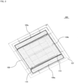
- Fig. 3 illustrates a suction grille structure 300 when the indoor device 100 of the exemplary embodiment is viewed from the indoor side.
- the grille 109 includes the suction grille 109b and the dummy grilles 109a arranged at both ends of the suction grille 109b.
- the grille 109 has a substantially square shape as viewed upwardly from the indoor side, and expands to a position adjacent to the blow port 108 formed at the edge portion of the decorative panel 107 on four sides thereof.
- the suction grille 109b arranged at a center portion of the grille 109 is in a rectangular shape having long sides in the right-left direction as viewed in the plane of paper in the illustrated exemplary embodiment.
- latch mechanisms 115 are formed at both short-side end portions of the suction grille 109b. The latch mechanisms 115 fix the suction grille 109b to the decorative panel 107.
- the suction grille 109b has a smaller area than the apparent area of the grille 109 and is decreased in weight, and therefore, the operability is improved.
- the dummy grille 109a is detachable from the decorative panel 107, and can respond to a change in the direction of extension of louvers of the grille 109 with respect to the decorative panel 107. Accordingly, the suction grille 109b can change an opening/closing direction thereof, and workability and maintainability are improved.
- Fig. 4 is an enlarged view of an internal structure 400 of the decorative panel 107 at a position indicated by an arrow C-C of Fig. 1 in a case where the decorative panel 107 is cut in a section in a direction parallel with the plane of paper.
- the exemplary embodiment illustrated in Fig. 4 corresponds to the end portion formed with the hinge mechanism.
- the blow port 108 is formed inside the decorative panel 107.
- a wind deflector 112 is movably held by a not-shown drive mechanism through a pivoting mechanism 113, thereby controlling the direction of conditioned air blown into the room.
- the thermal insulations 110 are arranged on both sides of the blow port 108, thereby preventing, e.g., condensation in the vicinity of the blow port 108.
- the dummy grille 109a is placed between the blow port 108 and the suction grille 109b in a region which is typically present as a space worsening the design, and therefore, the indoor-side design of the indoor device 100 is improved and the operability upon maintenance is improved.
- a filter 111 is placed on the suction grille 109b on an indoor device 100 side, and the louvers extending parallel with a louver structure of the dummy grille 109a is formed on the indoor side of the grille 109.
- unity of the dummy grille 109a and the suction grille 109b is improved.
- the dummy grille 109a of the present embodiment extends inwardly from a position in the vicinity of the blow port 108, and an inner end portion thereof is arranged to extend to the end portion of the suction grille 109b.
- a hinge 114 engaging with the inner end portion of the dummy grille 109a is formed.
- the suction grille 109b is held turnably about the dummy grille 109a in cooperation with a hinge receiving portion 114d formed at the dummy grille 109a.
- the hinge 114 of the present exemplary embodiment will be described.
- the hinge 114 includes a U-shaped structure having a substantially U-shaped section and including a tip end portion 114a extending to bend to the indoor side above the dummy grille 109a, a base portion 114b extending from an end surface of the suction grille 109b toward the indoor device side, and a coupling portion 114c coupling the tip end portion 114a and the base portion 114b.
- the hinge 114 of the exemplary embodiment is configured such that a second U-shaped structure having the same shape is also arranged on the near side as viewed in the plane of paper of Fig. 4 and both U-shaped structures in a pair are coupled to each other at the tip end portions 114a in the vertical direction as viewed in the plane of paper.
- Both U-shaped structures in a pair form, by the base portions 114b, an aperture (not shown) in the vertical direction as viewed in the plane of paper such that a hinge stopper 114e is housed between both U-shaped structures.
- the hinge receiving portion 114d for receiving the tip end portions 114a of the hinge 114 is formed at the dummy grille 109a, and the hinge stopper 114e is formed at the end portion on a suction grille 109b side.
- the hinge 114 is movable in the right-left direction as viewed in the plane of paper with the hinge stopper 114e being housed in the aperture.
- a beam structure formed integrally with the decorative panel 107 extends, above the hinge 114, in the vertical direction as viewed in the plane of paper, thereby restricting the amount of movement of the hinge 114 in the upper-lower direction as viewed in the plane of paper.
- Fig. 5 illustrates a schematic view of an internal structure 500 in a case where the suction grille 109b is opened for, e.g., maintenance.
- the suction grille 109b becomes rotatable by release of the latch mechanism formed at the opposing end portion.
- the hinge 114 in almost horizontal arrangement is drawn to the right side as viewed in the plane of paper, and thereafter, the suction grille 109b is drawn laterally to a position at which opposing surfaces of the tip end portions 114a of the hinge 114 and the hinge receiving portion 114d are adjacent to each other.
- the suction grille 109b rotates clockwise about the tip end portions 114a as a pivot point, and accordingly, rotation of the suction grille 109b is allowed.
- the suction grille 109b is lifted upwardly as viewed in the plane of paper, and accordingly, the aperture formed by the hinge 114 and the hinge stopper 114e are disengaged from each other and the suction grille 109b is detached from the decorative panel 107.
- the suction grille 109b is detachable from the decorative panel 107.
- the operator accesses the inside of the indoor device 100 to perform not only replacement and cleaning of the filter 111 but also maintenance and inspection of internal elements of the indoor device 100.
- the entire area of the grille 109 increases, the weight of the suction grille 109b is smaller than that corresponding to an apparent area.
- Fig. 6 is an enlarged view of an internal structure 600 of the end portion including the latch mechanisms 115 arranged on the opposing side of the end portion of the decorative panel 107 illustrated in Figs. 4 and 5 .
- the latch mechanism 115 illustrated in Fig. 6 corresponds to the internal structure 600 in the section as viewed in the direction of an arrow indicated by a cut line D-D along the vertical direction as viewed in the plane of paper of Fig. 1 when the decorative panel 107 is cut along the cut line D-D.
- the latch mechanism 115 illustrated in Fig. 6 corresponds to the internal structure 600 in the section as viewed in the direction of an arrow indicated by a cut line D-D along the vertical direction as viewed in the plane of paper of Fig. 1 when the decorative panel 107 is cut along the cut line D-D.
- the latch mechanisms 115 having the function of detachably holding the suction grille 109b on the decorative panel 107 are formed at both end portions of the suction grille 109b separated from each other in the direction of the cut line D-D of Fig. 1 .
- the blow port 108 is formed at the end portion of the decorative panel, and in the blow port 108, the wind deflector 112 is rotatably held by the pivoting mechanism 113. As in the embodiment illustrated in Figs. 4 and 5 , conditioned air can be blown into the room to condition indoor air.
- the thermal insulations are, as in the opposing end portion, arranged on both sides of the blow port 108, and the suction grille 109b extends below the thermal insulation 110 arranged inside.
- the suction grille 109b extends to a position adjacent to the blow port 108.
- the opposing end portion of the suction grille 109b similarly extends to the blow port 108 on the opposing side.
- the suction grille 109b is in the rectangular shape as illustrated in Fig. 3 .
- the latch mechanism 115 configured to lock the suction grille 109b in a coordinating matter is formed.
- the latch mechanism 115 includes an operation hook 115a, a housing space 115c, and an engagement portion 115b integrated with the decorative panel 107.
- An elastic body 115d for biasing the operation hook 115a is housed in the housing space 115c.
- the operation hook 115a has such a structure that the operation hook 115a extends outwardly along an upper surface of the suction grille 109b from a knob protruding from between the louvers of the suction grille 109b, bends upwardly at a proper position of the suction grille 109b, and extends again to bend outwardly.
- An end portion of the operation hook 115a on the opposite side of the knob forms an engagement claw 115e engaging with the decorative panel 107.
- the housing space 115c is defined by a portion of the operation hook 115a extending along the upper surface of the suction grille 109b and a protruding portion of the operation hook 115a standing from an inner surface of the suction grille 109b.
- the elastic body 115d as a spring for biasing the engagement claw 115e of the operation hook 115a such that the engagement claw 115e protrudes outwardly is arranged in the housing space 115c.
- the engagement claw 115e of the operation hook 115a is fitted in the engagement portion 115b formed at the decorative panel 107, thereby fixing the suction grille 109b.
- the operator first moves the operation hook 115a in the direction of an arrow E, and pulls the engagement claw 115e out of the engagement portion 115b, and rotates the suction grille 109b downwardly as viewed in the plane of paper. Thereafter, the operator rotates the suction grille 109b downwardly as viewed in the plane of paper, and as necessary, detaches the suction grille 109b so that the operator can access the inside of the indoor device 100.
- the hanging wire 109c illustrated in Fig. 2 is fixed to a proper position of the suction grille 109b.
- the suction grille 109b can be held at a proper position, and e.g., unintended dropping of the suction grille 109b can be prevented.
- a first variation is such a form that the dummy grille 109a is attached to the decorative panel 107 with the attachment direction of the dummy grille 109a being rotated, for example.
- the grille 109 is formed in the substantially square shape, but the portion excluding the dummy grilles 109a is formed in the substantially rectangular shape.
- the direction of attachment of the dummy grille 109a to the decorative panel 107 is rotated 90° so that the direction of extension of the louvers of the grille 109 can be changed. Consequently, the workability when the indoor device 100 is placed in the room can be improved considering the design.
- Fig. 7 illustrates an exemplary variation. Note that in description of the variation, the same reference numerals are used to represent members having functions common or identical to those of the above-described embodiment, and description thereof will be omitted.
- the variation illustrated in Fig. 7 is an embodiment in which the grille 109 of an indoor device 700 can be lifted/lowered by lifting/lowering motors 713 and hanging wires.
- the indoor device 700 illustrated in Fig. 7 houses, in the housing 102 of the indoor device 100, the heat exchanger 103, the fan 105, and the fan motor 106 configured to drive the fan 105.
- Indoor air flows in the direction of the arrow A, flows toward the heat exchanger 103 along the air flow generated by the fan 105, and exchanges heat with refrigerant circulating in the heat exchanger 103.
- the conditioned air after heat exchange is, in the direction of the arrows B, discharged into the room through the blow port 108.
- the drain pan 104 is arranged below the heat exchanger 103, and collects drain water from the heat exchanger 103.
- the decorative panel 107 is placed on the indoor side of the housing 102.
- the grille 109 is detachably placed on the indoor side of the decorative panel 107.
- the grille 109 includes the suction grille 109b liftably held by the lifting/lowering motors 713 and the dummy grilles 109a arranged at both ends of the suction grille 109b.
- a portion inside the dummy grilles 109a is formed as the suction grille 109b formed in a quadrangular shape, more specifically the rectangular shape, separately from the dummy grilles 109a. Accordingly, a housing portion 715 for housing the suction grille 109b is formed at a portion inside the dummy grilles 109a. Wire attachment portions 710a to 710d formed at proper positions at four corners of the suction grille 109b are formed at the suction grille 109b.
- FIG. 7 illustrates only the wire attachment portions 710a, 710b arranged on the near side as viewed in the plane of paper.
- the hanging wires 712 for liftably holding the suction grille 109b are fixed to the wire attachment portions 710a, 710b through a wire holding mechanism.
- the filter 111 is placed on the surface of the suction grille 109b facing the indoor device 100.
- the lifting/lowering motors 713 and drums 714 are, through a proper mount member, arranged inside the housing 102.
- the lifting/lowering motor 713 turns the drum 714 to lift/lower the suction grille 109b fixed to the other end of the hanging wire 712.
- the lifting/lowering motors 713 lift the suction grille 109b to a position at which the dummy grilles 109a and the suction grille 109b are integrated.
- the lifting/lowering motors 713 are arranged on the right and left sides in the housing 102 in the variation illustrated in Fig. 7 , but the lifting/lowering motor 713 may be arranged on one side in the housing 102 as in, e.g., the configuration of Patent Literature 1. Two of the hanging wires 712 on one side may be driven by one lifting/lowering motor 713, and the other two hanging wires 712 may be driven by another lifting/lowering motor 713 to be driven in synchronization with the one lifting/lowering motor 713. Alternatively, the four hanging wires 712 may be wound or unwound by the single lifting/lowering motor 713, or may be each wound or unwound by the independent lifting/lowering motors 713.
- the lifting/lowering motors 713 are started in response to a command from a remote controller (not shown) for controlling the indoor device 100 to lower the suction grille 109b to a predetermined height so that the operator can access the inside of the housing 102.
- the grille 109 is also formed to extend to near the blow port 108 formed at the decorative panel 107 on four sides thereof, considering the design.
- the grille 109 of the present embodiment increases the apparent area of the grille 109 as a whole, and improves the design.
- the grille 109 is configured separately as the dummy grilles 109a and the suction grille 109b, and therefore, weight reduction and space saving are achieved.
- the design is improved while the operability and workability of the suction grille 109b are improved.
- the dummy grilles 109a may be formed on four sides of the decorative panel 107, and the suction grille 109b may be further decreased in weight.
- the hinge mechanism and the latch mechanism for rotatably holding the suction grille 109b are not necessarily used. Instead, e.g., a stopper mechanism configured to stop rotation of the lifting/lowering motors 713 to prevent reverse rotation in a case where the suction grille 109b is lifted to a predetermined position by the lifting/lowering motors 713 can be added.
- a typical manual or electrical latch mechanism for fixing the suction grille 109b to the decorative panel 107 may be formed at the grille 109.
- the ceiling embedded air-conditioner configured so that the grille can be shown large, opening/closing can be facilitated, and the suction grille structure can be decreased in weight regardless of an increase in the area of the grille.
Landscapes
- Engineering & Computer Science (AREA)
- Chemical & Material Sciences (AREA)
- Combustion & Propulsion (AREA)
- Mechanical Engineering (AREA)
- General Engineering & Computer Science (AREA)
- Air Filters, Heat-Exchange Apparatuses, And Housings Of Air-Conditioning Units (AREA)
Abstract
Description
- The present invention relates to an air-conditioner, and more specifically, relates to a ceiling embedded air-conditioner including a decorative panel attached to a lower portion of the ceiling embedded air-conditioner.
- A duct type unit has been employed as an indoor unit in a space where a design is considered to be important. However, with a recent increased demand for construction of a building at low cost, a ceiling cassette type requiring no duct work has been increasingly demanded. In response to such a demand, a decorative panel taking the middle between the duct type unit and the typical ceiling cassette type in terms of design has been proposed.
- For a decorative panel of a ceiling embedded air-conditioner, a structure in which a suction grille expands to the vicinity of a blow port provided at an outer peripheral portion of the decorative panel is preferred considering the design. At the periphery of the blow port, a thermal insulation having a thickness of equal to or greater than a certain thickness needs to be provided for, e.g., preventing condensation caused by blowing of conditioned air.
-
Fig. 8 illustrates a schematic structure of anindoor device 800 of a typical ceiling embedded air-conditioner. The typicalindoor device 800 is configured such that adecorative panel 801 placed adjacent to a ceiling (not shown) is arranged on an indoor side. Ablow port 802 is formed inside thedecorative panel 801, and awind deflector 806 is arranged inside theblow port 802 through aproper pivoting mechanism 807 and a proper drive mechanism. Aheat exchanger 810 and adrain pan 811 are arranged in abody 809 of theindoor device 800. Theheat exchanger 810 performs heat exchange between a heat exchange medium sent from an outdoor device (not shown) and indoor air. The conditioned air after heat exchange is blown into a room through theblow port 802, and conditions air in the room. Thedrain pan 811 is arranged below theheat exchanger 810 to receive drain water from theheat exchanger 810. -
Thermal insulations 805 for preventing condensation are arranged on both sides of theblow port 802, and asuction grille 803 extends to near the innerthermal insulation 805. Thesuction grille 803 includes an opening for introducing indoor air into theindoor device 800, and a filter (not shown) is placed on anindoor device 800 side of thesuction grille 803. - Due to cleaning or replacement of the filter or maintenance of the
indoor device 800, thesuction grille 803 needs to be opened/closed. In the typicaldecorative panel 801, ahinge 808 engaging with thedecorative panel 801 is arranged at an end portion of thesuction grille 803. In response to a request such as maintenance, a knob arranged in the vicinity of an end portion of thesuction grille 803 on the right side as viewed in the plane of paper is operated to disconnect thesuction grille 803 from thedecorative panel 801. Thereafter, when thehinge 808 is rotated relative to thedecorative panel 801 by operator's operation, thesuction grille 803 rotates clockwise downwardly as viewed in the plane of paper. - In a case where an attempt is made to expand the
suction grille 803 to the vicinity of theblow port 802 in the configuration ofFig. 8 , it is difficult to ensure a space for providing thehinge 808 as the center of opening/closing due to the volume of thethermal insulations 805. For this reason, there is a problem that the operation of opening/closing thesuction grille 803 cannot be performed using a simple structure. On this point, aregion 804 formed between theblow port 802 and thesuction grille 803 can be taken as a region degrading a design in terms of the indoor-side design of thedecorative panel 801, and improvement of a hinge structure provides a margin for effective utilization. - In a case where the
suction grille 803 expands to the vicinity of theblow port 802, thesuction grille 803 is increased in size as compared to the typical suction grille. As a result, the weight of thesuction grille 803 increases, and there is a concern that when the same configuration is employed for a decorative panel with a lifting/lowering grille, the output of a suction grille lifting/lowering motor is insufficient. - Study has been conducted so far on various configurations for performing a work inside an indoor device. For example,
WO 2018/179136 A (Patent Literature 1) describes a ceiling embedded air-conditioner for improving workability in an indoor device, the ceiling embedded air-conditioner including a suction grille provided on a design side of a decorative panel and side panels provided at the right and left of the suction grille. In a state in which the decorative panel is attached to a body, the side panels detachably attached to the decorative panel through the suction grille opened by turning can be detached. - The indoor device described in
Patent Literature 1 can improve accessibility to the inside of the indoor device. However, the side panels not relating to the design are added, and for this reason, the design of the indoor device is degraded. Moreover, the suction grille extends to near a blow port, and therefore,Patent Literature 1 is not intended to improve the design. -
JP-A-2-171526 -
- Patent Literature 1:
WO 2018/179136 A - Patent Literature 2:
JP-A-2-171526 - The present invention has been made in view of the above-described problems, and an object of the present invention is to provide a ceiling embedded air-conditioner configured so that a suction grille can be shown large, opening/closing can be facilitated, and a suction grille structure can be decreased in weight regardless of an increase in the area of the suction grille.
- That is, according to the present invention, a ceiling embedded air-conditioner includes an indoor device having a fan, a fan motor, and a heat exchanger. The indoor device includes a decorative panel attached facing an air-conditioning space and having a suction port and a blow port and a grille attached to the decorative panel. The grille has a suction grille provided at the suction port and a dummy grille extending from at least one end portion of the suction grille and provided between the suction port and the blow port.
- According to the present invention, the ceiling embedded air-conditioner including the suction grille structure with the improved design can be provided.
-
-
Fig. 1 is a schematic sectional view of anindoor device 100 of an exemplary embodiment. -
Fig. 2 is a view illustrating anexemplary form 200 in which asuction grille 109b of theindoor device 100 is opened in the exemplary embodiment. -
Fig. 3 is a view illustrating asuction grille structure 300 when theindoor device 100 of the exemplary embodiment is viewed from an indoor side. -
Fig. 4 is an enlarged view illustrating aninternal structure 400 of adecorative panel 107 in a direction along an arrow C-C ofFig. 1 . -
Fig. 5 is a schematic view of aninternal structure 500 in a case where thesuction grille 109b is opened for, e.g., maintenance. -
Fig. 6 is an enlarged view of aninternal structure 600 of an end portion corresponding to thedecorative panel 107 illustrated inFigs. 4 and5 , the view being enlarged in the direction of a cut line D-D ofFig. 1 . -
Fig. 7 is a view illustrating an exemplary variation. -
Fig. 8 is a view illustrating a structure at an edge portion of anindoor device 800 of a typical ceiling embedded air-conditioner. - Hereinafter, the present invention will be described with reference to an exemplary embodiment, but is not limited to the embodiment described later. Moreover, the drawings are used for the sake of easy understanding of the present invention, and shall not be interpreted as those attached to limit the present invention. Further, a term "near," "vicinity," or "adjacent" will be used as a normal meaning understood as "near," "vicinity," or "adjacent" by those skilled in the art, and does not necessarily mean actual contact.
-
Fig. 1 illustrates a schematic sectional view of anindoor device 100 of the exemplary embodiment. Theindoor device 100 illustrated inFig. 1 is anindoor device 100 of a ceiling embedded air-conditioner, and ahousing 102 of theindoor device 100 houses aheat exchanger 103, afan 105, and afan motor 106 configured to drive thefan 105. Indoor air is sucked in the direction of an arrow A, flows toward theheat exchanger 103 along an air flow generated by thefan 105, and exchanges heat with a heat exchange medium circulating in theheat exchanger 103. - The conditioned air after heat exchange is, in the direction of arrows B, discharged into a room as an exemplary air-conditioning space through a
blow port 108. Adrain pan 104 is arranged below theheat exchanger 103, and collects drain water, dirt and the like from theheat exchanger 103. - A
decorative panel 107 is placed on an indoor side of thehousing 102. Agrille 109 is detachably placed on the indoor side of thedecorative panel 107. Thegrille 109 includes adummy grille 109a arranged at least at one end portion and asuction grille 109b. Thedummy grille 109a of thegrille 109 extends adjacent to theblow port 108 for improving the design of theindoor device 100 on the indoor side. - Note that in the preferred embodiment of the present disclosure, a phrase "adjacent to the
blow port 108" means that thedummy grille 109a extends, with at least a width of equal to or greater than 1/2 of a width between theblow port 108 and thesuction grille 109b, from an end portion of thesuction grille 109b in a region between theblow port 108 and thesuction grille 109b. Thedummy grille 109a is detachably fixed to thedecorative panel 107, and an attachment direction thereof is such a direction that thedummy grille 109a can be also fixed to, e.g., a position rotated 90° with respect to thedecorative panel 107. - One end portion of the
suction grille 109b is coupled to onedummy grille 109a through a hinge mechanism, and the opposing end portion thereof is coupled to thedecorative panel 107 through a latch mechanism. By thedummy grilles 109a and the latch mechanism, thesuction grille 109b is fixed to thedecorative panel 107. Thesuction grille 109b and thedummy grilles 109a arranged at both ends of thesuction grille 109b increase the area of thegrille 109, and reduce the weight of thesuction grille 109b. Thus, in the present exemplary embodiment, the design of theindoor device 100 can be improved. In addition, a movable portion of thegrille 109 can be decreased in weight, and operability can be improved. - The
blow port 108 is formed at an outer edge portion of thegrille 109 of thedecorative panel 107. For, e.g., preventing condensation,thermal insulations 110 are arranged at inner and outer ends of theblow port 108. Conditioned air is blown in the direction of the arrows B through theblow port 108, and achieves air-conditioning in the room. - Upon, e.g., filter replacement, cleaning, inspection, or component replacement for the
indoor device 100 illustrated inFig. 1 , thesuction grille 109b of thegrille 109 is, in the present exemplary embodiment, rotatably moved clockwise downwardly as viewed in the plane of paper such that the inside of theindoor device 100 is exposed. Accordingly, an access to the inside of theindoor device 100 can be made. -
Fig. 2 illustrates anexemplary form 200 in which thesuction grille 109b of theindoor device 100 is opened in the exemplary embodiment. One end of thesuction grille 109b engages with thedummy grille 109a through the hinge mechanism, and the other end of thesuction grille 109b is held on thedecorative panel 107 by the latch mechanism. In a case where thesuction grille 109b is opened in the exemplary embodiment illustrated inFig. 2 , the latch mechanism arranged on the right side as viewed in the plane of paper is released to open thesuction grille 109b from one end thereof, and an operator rotates thesuction grille 109b downwardly as viewed in the plane of paper while holding the movable end portion of thesuction grille 109b. - A
hanging wire 109c of which one end is fixed to thedecorative panel 107 is coupled to a center portion of thesuction grille 109b, and thesuction grille 109b is held by thehanging wire 109c after having turned to an acceptable range of thehanging wire 109c. - In the exemplary embodiment illustrated in
Fig. 2 , the left end portion of thesuction grille 109b as viewed in the plane of paper is turnably coupled to thedummy grille 109a through the hinge mechanism. Thesuction grille 109b rotates through the hinge mechanism of thedummy grille 109a in association with lowering of the right end portion of thesuction grille 109b so that thesuction grille 109b can rotatably move. -
Fig. 3 illustrates asuction grille structure 300 when theindoor device 100 of the exemplary embodiment is viewed from the indoor side. As illustrated inFig. 3 , thegrille 109 includes thesuction grille 109b and thedummy grilles 109a arranged at both ends of thesuction grille 109b. Thegrille 109 has a substantially square shape as viewed upwardly from the indoor side, and expands to a position adjacent to theblow port 108 formed at the edge portion of thedecorative panel 107 on four sides thereof. - Thus, the
suction grille 109b arranged at a center portion of thegrille 109 is in a rectangular shape having long sides in the right-left direction as viewed in the plane of paper in the illustrated exemplary embodiment. Moreover, in the exemplary embodiment illustrated inFig. 3 , latchmechanisms 115 are formed at both short-side end portions of thesuction grille 109b. Thelatch mechanisms 115 fix thesuction grille 109b to thedecorative panel 107. Thus, thesuction grille 109b has a smaller area than the apparent area of thegrille 109 and is decreased in weight, and therefore, the operability is improved. Thedummy grille 109a is detachable from thedecorative panel 107, and can respond to a change in the direction of extension of louvers of thegrille 109 with respect to thedecorative panel 107. Accordingly, thesuction grille 109b can change an opening/closing direction thereof, and workability and maintainability are improved. -
Fig. 4 is an enlarged view of aninternal structure 400 of thedecorative panel 107 at a position indicated by an arrow C-C ofFig. 1 in a case where thedecorative panel 107 is cut in a section in a direction parallel with the plane of paper. The exemplary embodiment illustrated inFig. 4 corresponds to the end portion formed with the hinge mechanism. As illustrated inFig. 4 , theblow port 108 is formed inside thedecorative panel 107. In theblow port 108, awind deflector 112 is movably held by a not-shown drive mechanism through apivoting mechanism 113, thereby controlling the direction of conditioned air blown into the room. - The
thermal insulations 110 are arranged on both sides of theblow port 108, thereby preventing, e.g., condensation in the vicinity of theblow port 108. In the present embodiment, thedummy grille 109a is placed between theblow port 108 and thesuction grille 109b in a region which is typically present as a space worsening the design, and therefore, the indoor-side design of theindoor device 100 is improved and the operability upon maintenance is improved. - A
filter 111 is placed on thesuction grille 109b on anindoor device 100 side, and the louvers extending parallel with a louver structure of thedummy grille 109a is formed on the indoor side of thegrille 109. Thus, unity of thedummy grille 109a and thesuction grille 109b is improved. - The
dummy grille 109a of the present embodiment extends inwardly from a position in the vicinity of theblow port 108, and an inner end portion thereof is arranged to extend to the end portion of thesuction grille 109b. At the outer end portion of thesuction grille 109b, ahinge 114 engaging with the inner end portion of thedummy grille 109a is formed. Thesuction grille 109b is held turnably about thedummy grille 109a in cooperation with ahinge receiving portion 114d formed at thedummy grille 109a. - The
hinge 114 of the present exemplary embodiment will be described. Thehinge 114 includes a U-shaped structure having a substantially U-shaped section and including atip end portion 114a extending to bend to the indoor side above thedummy grille 109a, abase portion 114b extending from an end surface of thesuction grille 109b toward the indoor device side, and acoupling portion 114c coupling thetip end portion 114a and thebase portion 114b. - Further, the
hinge 114 of the exemplary embodiment is configured such that a second U-shaped structure having the same shape is also arranged on the near side as viewed in the plane of paper ofFig. 4 and both U-shaped structures in a pair are coupled to each other at thetip end portions 114a in the vertical direction as viewed in the plane of paper. Both U-shaped structures in a pair form, by thebase portions 114b, an aperture (not shown) in the vertical direction as viewed in the plane of paper such that ahinge stopper 114e is housed between both U-shaped structures. - The
hinge receiving portion 114d for receiving thetip end portions 114a of thehinge 114 is formed at thedummy grille 109a, and thehinge stopper 114e is formed at the end portion on asuction grille 109b side. Thehinge 114 is movable in the right-left direction as viewed in the plane of paper with thehinge stopper 114e being housed in the aperture. A beam structure formed integrally with thedecorative panel 107 extends, above thehinge 114, in the vertical direction as viewed in the plane of paper, thereby restricting the amount of movement of thehinge 114 in the upper-lower direction as viewed in the plane of paper. -
Fig. 5 illustrates a schematic view of aninternal structure 500 in a case where thesuction grille 109b is opened for, e.g., maintenance. In this case, thesuction grille 109b becomes rotatable by release of the latch mechanism formed at the opposing end portion. In the case of moving thesuction grille 109b, thehinge 114 in almost horizontal arrangement is drawn to the right side as viewed in the plane of paper, and thereafter, thesuction grille 109b is drawn laterally to a position at which opposing surfaces of thetip end portions 114a of thehinge 114 and thehinge receiving portion 114d are adjacent to each other. - Thereafter, when the not-shown other end of the
suction grille 109b is moved downwardly as viewed in the plane of paper, thesuction grille 109b rotates clockwise about thetip end portions 114a as a pivot point, and accordingly, rotation of thesuction grille 109b is allowed. In a state in which thesuction grille 109b has been rotated to a predetermined position, thesuction grille 109b is lifted upwardly as viewed in the plane of paper, and accordingly, the aperture formed by thehinge 114 and thehinge stopper 114e are disengaged from each other and thesuction grille 109b is detached from thedecorative panel 107. With the above-described configuration, thesuction grille 109b is detachable from thedecorative panel 107. - In the state illustrated in
Fig. 2 or the state in which thesuction grille 109b is detached, the operator accesses the inside of theindoor device 100 to perform not only replacement and cleaning of thefilter 111 but also maintenance and inspection of internal elements of theindoor device 100. Although the entire area of thegrille 109 increases, the weight of thesuction grille 109b is smaller than that corresponding to an apparent area. Thus, the operability and the workability can be improved while the design is improved. -
Fig. 6 is an enlarged view of aninternal structure 600 of the end portion including thelatch mechanisms 115 arranged on the opposing side of the end portion of thedecorative panel 107 illustrated inFigs. 4 and5 . Note that thelatch mechanism 115 illustrated inFig. 6 corresponds to theinternal structure 600 in the section as viewed in the direction of an arrow indicated by a cut line D-D along the vertical direction as viewed in the plane of paper ofFig. 1 when thedecorative panel 107 is cut along the cut line D-D. On the side opposing the end portion of thedecorative panel 107 illustrated inFigs. 4 and5 , thelatch mechanisms 115 having the function of detachably holding thesuction grille 109b on thedecorative panel 107 are formed at both end portions of thesuction grille 109b separated from each other in the direction of the cut line D-D ofFig. 1 . - The structure of
Fig. 6 will be described. Theblow port 108 is formed at the end portion of the decorative panel, and in theblow port 108, thewind deflector 112 is rotatably held by thepivoting mechanism 113. As in the embodiment illustrated inFigs. 4 and5 , conditioned air can be blown into the room to condition indoor air. - The thermal insulations are, as in the opposing end portion, arranged on both sides of the
blow port 108, and thesuction grille 109b extends below thethermal insulation 110 arranged inside. For improving the design of thedecorative panel 107 on the indoor side, thesuction grille 109b extends to a position adjacent to theblow port 108. The opposing end portion of thesuction grille 109b similarly extends to theblow port 108 on the opposing side. In description of the exemplary embodiment, thesuction grille 109b is in the rectangular shape as illustrated inFig. 3 . - Across the end portion of the
suction grille 109b and the short-side end portion of thedecorative panel 107 facing thesuction grille 109b, thelatch mechanism 115 configured to lock thesuction grille 109b in a coordinating matter is formed. Thelatch mechanism 115 includes anoperation hook 115a, ahousing space 115c, and anengagement portion 115b integrated with thedecorative panel 107. Anelastic body 115d for biasing theoperation hook 115a is housed in thehousing space 115c. - The
operation hook 115a has such a structure that theoperation hook 115a extends outwardly along an upper surface of thesuction grille 109b from a knob protruding from between the louvers of thesuction grille 109b, bends upwardly at a proper position of thesuction grille 109b, and extends again to bend outwardly. An end portion of theoperation hook 115a on the opposite side of the knob forms anengagement claw 115e engaging with thedecorative panel 107. - The
housing space 115c is defined by a portion of theoperation hook 115a extending along the upper surface of thesuction grille 109b and a protruding portion of theoperation hook 115a standing from an inner surface of thesuction grille 109b. Theelastic body 115d as a spring for biasing theengagement claw 115e of theoperation hook 115a such that theengagement claw 115e protrudes outwardly is arranged in thehousing space 115c. - At a fixed position of the
suction grille 109b, theengagement claw 115e of theoperation hook 115a is fitted in theengagement portion 115b formed at thedecorative panel 107, thereby fixing thesuction grille 109b. In a case where the operator attempts to move thesuction grille 109b to access the inside of theindoor device 100, the operator first moves theoperation hook 115a in the direction of an arrow E, and pulls theengagement claw 115e out of theengagement portion 115b, and rotates thesuction grille 109b downwardly as viewed in the plane of paper. Thereafter, the operator rotates thesuction grille 109b downwardly as viewed in the plane of paper, and as necessary, detaches thesuction grille 109b so that the operator can access the inside of theindoor device 100. - The
hanging wire 109c illustrated inFig. 2 is fixed to a proper position of thesuction grille 109b. Thus, thesuction grille 109b can be held at a proper position, and e.g., unintended dropping of thesuction grille 109b can be prevented. - A first variation is such a form that the
dummy grille 109a is attached to thedecorative panel 107 with the attachment direction of thedummy grille 109a being rotated, for example. As illustrated inFig. 3 , thegrille 109 is formed in the substantially square shape, but the portion excluding thedummy grilles 109a is formed in the substantially rectangular shape. Thus, the direction of attachment of thedummy grille 109a to thedecorative panel 107 is rotated 90° so that the direction of extension of the louvers of thegrille 109 can be changed. Consequently, the workability when theindoor device 100 is placed in the room can be improved considering the design. -
Fig. 7 illustrates an exemplary variation. Note that in description of the variation, the same reference numerals are used to represent members having functions common or identical to those of the above-described embodiment, and description thereof will be omitted. The variation illustrated inFig. 7 is an embodiment in which thegrille 109 of anindoor device 700 can be lifted/lowered by lifting/loweringmotors 713 and hanging wires. - The
indoor device 700 illustrated inFig. 7 houses, in thehousing 102 of theindoor device 100, theheat exchanger 103, thefan 105, and thefan motor 106 configured to drive thefan 105. Indoor air flows in the direction of the arrow A, flows toward theheat exchanger 103 along the air flow generated by thefan 105, and exchanges heat with refrigerant circulating in theheat exchanger 103. - The conditioned air after heat exchange is, in the direction of the arrows B, discharged into the room through the
blow port 108. Thedrain pan 104 is arranged below theheat exchanger 103, and collects drain water from theheat exchanger 103. - The
decorative panel 107 is placed on the indoor side of thehousing 102. Thegrille 109 is detachably placed on the indoor side of thedecorative panel 107. Thegrille 109 includes thesuction grille 109b liftably held by the lifting/loweringmotors 713 and thedummy grilles 109a arranged at both ends of thesuction grille 109b. - A portion inside the
dummy grilles 109a is formed as thesuction grille 109b formed in a quadrangular shape, more specifically the rectangular shape, separately from thedummy grilles 109a. Accordingly, ahousing portion 715 for housing thesuction grille 109b is formed at a portion inside thedummy grilles 109a.Wire attachment portions 710a to 710d formed at proper positions at four corners of thesuction grille 109b are formed at thesuction grille 109b. - Note that
Fig. 7 illustrates only thewire attachment portions wires 712 for liftably holding thesuction grille 109b are fixed to thewire attachment portions filter 111 is placed on the surface of thesuction grille 109b facing theindoor device 100. - The lifting/lowering
motors 713 anddrums 714 are, through a proper mount member, arranged inside thehousing 102. The lifting/loweringmotor 713 turns thedrum 714 to lift/lower thesuction grille 109b fixed to the other end of thehanging wire 712. In normal operation of theindoor device 100, the lifting/loweringmotors 713 lift thesuction grille 109b to a position at which thedummy grilles 109a and thesuction grille 109b are integrated. - The lifting/lowering
motors 713 are arranged on the right and left sides in thehousing 102 in the variation illustrated inFig. 7 , but the lifting/loweringmotor 713 may be arranged on one side in thehousing 102 as in, e.g., the configuration ofPatent Literature 1. Two of the hangingwires 712 on one side may be driven by one lifting/loweringmotor 713, and the other two hangingwires 712 may be driven by another lifting/loweringmotor 713 to be driven in synchronization with the one lifting/loweringmotor 713. Alternatively, the four hangingwires 712 may be wound or unwound by the single lifting/loweringmotor 713, or may be each wound or unwound by the independent lifting/loweringmotors 713. - The following arrangement is made: upon, e.g., filter replacement, cleaning, inspection, or component replacement for the
indoor device 700, the lifting/loweringmotors 713 are started in response to a command from a remote controller (not shown) for controlling theindoor device 100 to lower thesuction grille 109b to a predetermined height so that the operator can access the inside of thehousing 102. - In the variation, the
grille 109 is also formed to extend to near theblow port 108 formed at thedecorative panel 107 on four sides thereof, considering the design. Thus, thegrille 109 of the present embodiment increases the apparent area of thegrille 109 as a whole, and improves the design. However, in the variation, thegrille 109 is configured separately as thedummy grilles 109a and thesuction grille 109b, and therefore, weight reduction and space saving are achieved. Thus, the design is improved while the operability and workability of thesuction grille 109b are improved. Note that in another variation, thedummy grilles 109a may be formed on four sides of thedecorative panel 107, and thesuction grille 109b may be further decreased in weight. - Note that in the variation, the hinge mechanism and the latch mechanism for rotatably holding the
suction grille 109b are not necessarily used. Instead, e.g., a stopper mechanism configured to stop rotation of the lifting/loweringmotors 713 to prevent reverse rotation in a case where thesuction grille 109b is lifted to a predetermined position by the lifting/loweringmotors 713 can be added. In another variation, a typical manual or electrical latch mechanism for fixing thesuction grille 109b to thedecorative panel 107 may be formed at thegrille 109. - In the variations described above, the ceiling embedded air-conditioner configured so that the grille can be shown large, opening/closing can be facilitated, and the suction grille structure can be decreased in weight regardless of an increase in the area of the grille.
-
- 100:
- indoor device
- 102:
- housing
- 103:
- heat exchanger
- 104:
- drain pan
- 105:
- fan
- 106:
- fan motor
- 107:
- decorative panel
- 108:
- blow port
- 109:
- grille
- 109a:
- dummy grille
- 109b:
- suction grille
- 109c:
- hanging wire
- 110:
- thermal insulation
- 114:
- hinge
- 114a:
- tip end portion
- 114b:
- base portion
- 114c:
- coupling portion
- 114d:
- hinge receiving portion
- 114e:
- hinge stopper
- 115:
- latch mechanism
Claims (5)
- A ceiling embedded air-conditioner comprising:an indoor device including a fan, a fan motor, and a heat exchanger,wherein the indoor device includes a decorative panel attached facing an air-conditioning space and having a suction port and a blow port and a grille attached to the decorative panel, andthe grille has a suction grille provided at the suction port and a dummy grille extending from at least one end portion of the suction grille and provided between the suction port and the blow port.
- The ceiling embedded air-conditioner according to claim 1, wherein
the suction grille is disposed between the dummy grilles. - The ceiling embedded air-conditioner according to claim 1, wherein
the dummy grille extends, with at least a width of equal to or greater than 1/2 of a width between the blow port and the suction grille, from an end portion of the suction grille. - The ceiling embedded air-conditioner according to claim 1, wherein
the suction grille is configured rotatably about the dummy grille. - The ceiling embedded air-conditioner according to claim 1, wherein
the indoor device includes, above the dummy grille, a hinge receiving portion configured to house a hinge capable of opening/closing the suction grille.
Applications Claiming Priority (1)
| Application Number | Priority Date | Filing Date | Title |
|---|---|---|---|
| PCT/JP2020/008105 WO2021171503A1 (en) | 2020-02-27 | 2020-02-27 | Ceiling embedded-type air conditioner |
Publications (3)
| Publication Number | Publication Date |
|---|---|
| EP4148336A1 true EP4148336A1 (en) | 2023-03-15 |
| EP4148336A4 EP4148336A4 (en) | 2024-01-03 |
| EP4148336B1 EP4148336B1 (en) | 2025-12-31 |
Family
ID=77490409
Family Applications (1)
| Application Number | Title | Priority Date | Filing Date |
|---|---|---|---|
| EP20904233.2A Active EP4148336B1 (en) | 2020-02-27 | 2020-02-27 | CEILING-INSIDE AIR CONDITIONING |
Country Status (4)
| Country | Link |
|---|---|
| EP (1) | EP4148336B1 (en) |
| JP (1) | JP7086283B2 (en) |
| CN (1) | CN113646591B (en) |
| WO (1) | WO2021171503A1 (en) |
Family Cites Families (10)
| Publication number | Priority date | Publication date | Assignee | Title |
|---|---|---|---|---|
| JPH0656266B2 (en) | 1988-12-23 | 1994-07-27 | 松下電器産業株式会社 | Combined air conditioner |
| JP3324676B2 (en) * | 1996-03-29 | 2002-09-17 | 株式会社富士通ゼネラル | Air conditioner |
| JP3145078B2 (en) * | 1997-07-07 | 2001-03-12 | 株式会社日立製作所 | Ceiling-mounted air conditioner |
| JP2000240967A (en) * | 1999-02-19 | 2000-09-08 | Fujitsu General Ltd | Top-mounted air conditioner |
| JP4224276B2 (en) * | 2002-10-15 | 2009-02-12 | 東芝キヤリア株式会社 | Embedded ceiling air conditioner |
| JP5401355B2 (en) | 2009-10-20 | 2014-01-29 | 日立アプライアンス株式会社 | Air conditioner indoor unit |
| JP6444224B2 (en) | 2015-03-06 | 2018-12-26 | 日立ジョンソンコントロールズ空調株式会社 | Air conditioner indoor unit |
| JP2017110826A (en) * | 2015-12-14 | 2017-06-22 | 三菱電機ビルテクノサービス株式会社 | Washable intermediate*high performance panel filter |
| US20200318853A1 (en) | 2017-03-29 | 2020-10-08 | Mitsubishi Electric Corporation | Ceiling-embedded air-conditioning apparatus |
| JP7161667B2 (en) * | 2018-03-30 | 2022-10-27 | 株式会社富士通ゼネラル | air conditioner |
-
2020
- 2020-02-27 JP JP2021518205A patent/JP7086283B2/en active Active
- 2020-02-27 EP EP20904233.2A patent/EP4148336B1/en active Active
- 2020-02-27 CN CN202080006588.5A patent/CN113646591B/en active Active
- 2020-02-27 WO PCT/JP2020/008105 patent/WO2021171503A1/en not_active Ceased
Also Published As
| Publication number | Publication date |
|---|---|
| EP4148336A4 (en) | 2024-01-03 |
| EP4148336B1 (en) | 2025-12-31 |
| CN113646591A (en) | 2021-11-12 |
| JP7086283B2 (en) | 2022-06-17 |
| CN113646591B (en) | 2022-12-16 |
| WO2021171503A1 (en) | 2021-09-02 |
| JPWO2021171503A1 (en) | 2021-09-02 |
Similar Documents
| Publication | Publication Date | Title |
|---|---|---|
| KR101781845B1 (en) | Indoor unit of air conditioner | |
| KR20040082957A (en) | Wall Mounted Air Conditioner | |
| JP2006300433A (en) | Air conditioner | |
| CN113203123B (en) | Wall-mounted air conditioner indoor unit and air conditioner | |
| EP4148336B1 (en) | CEILING-INSIDE AIR CONDITIONING | |
| JP5104993B1 (en) | Refrigeration unit outdoor unit | |
| JP2004301424A (en) | Air conditioner | |
| JP5201049B2 (en) | Bathroom ventilation dryer | |
| KR101093764B1 (en) | Multi-directional discharge air conditioner | |
| JP6538118B2 (en) | Air conditioner | |
| JP2001027428A (en) | Air conditioner | |
| JP3322589B2 (en) | Air conditioner | |
| JP3221288B2 (en) | Fan coil unit | |
| JP3443854B2 (en) | Air conditioner | |
| US20230243551A1 (en) | Indoor unit for an air conditioner | |
| US20250362053A1 (en) | Indoor unit of air conditioner | |
| JP2017003167A (en) | Ceiling embedded type air conditioner | |
| JPH0322654Y2 (en) | ||
| CN220958687U (en) | Ceiling machine and air conditioner | |
| JP2013096634A (en) | Air conditioner | |
| JP3306109B2 (en) | Air conditioner | |
| KR20070069537A (en) | Air conditioner | |
| WO2025120691A1 (en) | Ceiling-embedded air conditioner | |
| CN213237759U (en) | Air conditioner outdoor unit, air conditioner outdoor unit in pair suitable for building and building | |
| JP2005282949A (en) | Air conditioning device |
Legal Events
| Date | Code | Title | Description |
|---|---|---|---|
| STAA | Information on the status of an ep patent application or granted ep patent |
Free format text: STATUS: UNKNOWN |
|
| STAA | Information on the status of an ep patent application or granted ep patent |
Free format text: STATUS: THE INTERNATIONAL PUBLICATION HAS BEEN MADE |
|
| PUAI | Public reference made under article 153(3) epc to a published international application that has entered the european phase |
Free format text: ORIGINAL CODE: 0009012 |
|
| STAA | Information on the status of an ep patent application or granted ep patent |
Free format text: STATUS: REQUEST FOR EXAMINATION WAS MADE |
|
| 17P | Request for examination filed |
Effective date: 20210628 |
|
| AK | Designated contracting states |
Kind code of ref document: A1 Designated state(s): AL AT BE BG CH CY CZ DE DK EE ES FI FR GB GR HR HU IE IS IT LI LT LU LV MC MK MT NL NO PL PT RO RS SE SI SK SM TR |
|
| DAV | Request for validation of the european patent (deleted) | ||
| DAX | Request for extension of the european patent (deleted) | ||
| A4 | Supplementary search report drawn up and despatched |
Effective date: 20231204 |
|
| RIC1 | Information provided on ipc code assigned before grant |
Ipc: F24F 1/0047 20190101ALI20231128BHEP Ipc: F24F 13/20 20060101AFI20231128BHEP |
|
| GRAP | Despatch of communication of intention to grant a patent |
Free format text: ORIGINAL CODE: EPIDOSNIGR1 |
|
| STAA | Information on the status of an ep patent application or granted ep patent |
Free format text: STATUS: GRANT OF PATENT IS INTENDED |
|
| INTG | Intention to grant announced |
Effective date: 20250722 |
|
| GRAS | Grant fee paid |
Free format text: ORIGINAL CODE: EPIDOSNIGR3 |
|
| GRAA | (expected) grant |
Free format text: ORIGINAL CODE: 0009210 |
|
| STAA | Information on the status of an ep patent application or granted ep patent |
Free format text: STATUS: THE PATENT HAS BEEN GRANTED |
|
| AK | Designated contracting states |
Kind code of ref document: B1 Designated state(s): AL AT BE BG CH CY CZ DE DK EE ES FI FR GB GR HR HU IE IS IT LI LT LU LV MC MK MT NL NO PL PT RO RS SE SI SK SM TR |
|
| REG | Reference to a national code |
Ref country code: CH Ref legal event code: F10 Free format text: ST27 STATUS EVENT CODE: U-0-0-F10-F00 (AS PROVIDED BY THE NATIONAL OFFICE) Effective date: 20251231 Ref country code: GB Ref legal event code: FG4D |
|
| REG | Reference to a national code |
Ref country code: DE Ref legal event code: R096 Ref document number: 602020064969 Country of ref document: DE |
|
| REG | Reference to a national code |
Ref country code: IE Ref legal event code: FG4D |
|
| REG | Reference to a national code |
Ref country code: LT Ref legal event code: MG9D |
|
| PG25 | Lapsed in a contracting state [announced via postgrant information from national office to epo] |
Ref country code: NO Free format text: LAPSE BECAUSE OF FAILURE TO SUBMIT A TRANSLATION OF THE DESCRIPTION OR TO PAY THE FEE WITHIN THE PRESCRIBED TIME-LIMIT Effective date: 20260331 |
|
| PG25 | Lapsed in a contracting state [announced via postgrant information from national office to epo] |
Ref country code: HR Free format text: LAPSE BECAUSE OF FAILURE TO SUBMIT A TRANSLATION OF THE DESCRIPTION OR TO PAY THE FEE WITHIN THE PRESCRIBED TIME-LIMIT Effective date: 20251231 Ref country code: FI Free format text: LAPSE BECAUSE OF FAILURE TO SUBMIT A TRANSLATION OF THE DESCRIPTION OR TO PAY THE FEE WITHIN THE PRESCRIBED TIME-LIMIT Effective date: 20251231 |
|
| PG25 | Lapsed in a contracting state [announced via postgrant information from national office to epo] |
Ref country code: RS Free format text: LAPSE BECAUSE OF FAILURE TO SUBMIT A TRANSLATION OF THE DESCRIPTION OR TO PAY THE FEE WITHIN THE PRESCRIBED TIME-LIMIT Effective date: 20260331 |
|
| PGFP | Annual fee paid to national office [announced via postgrant information from national office to epo] |
Ref country code: FR Payment date: 20260226 Year of fee payment: 7 |
|
| PG25 | Lapsed in a contracting state [announced via postgrant information from national office to epo] |
Ref country code: LV Free format text: LAPSE BECAUSE OF FAILURE TO SUBMIT A TRANSLATION OF THE DESCRIPTION OR TO PAY THE FEE WITHIN THE PRESCRIBED TIME-LIMIT Effective date: 20251231 |
|
| PG25 | Lapsed in a contracting state [announced via postgrant information from national office to epo] |
Ref country code: BG Free format text: LAPSE BECAUSE OF FAILURE TO SUBMIT A TRANSLATION OF THE DESCRIPTION OR TO PAY THE FEE WITHIN THE PRESCRIBED TIME-LIMIT Effective date: 20251231 |
|
| REG | Reference to a national code |
Ref country code: NL Ref legal event code: MP Effective date: 20251231 |
|
| REG | Reference to a national code |
Ref country code: AT Ref legal event code: MK05 Ref document number: 1873650 Country of ref document: AT Kind code of ref document: T Effective date: 20251231 |
|
| PG25 | Lapsed in a contracting state [announced via postgrant information from national office to epo] |
Ref country code: NL Free format text: LAPSE BECAUSE OF FAILURE TO SUBMIT A TRANSLATION OF THE DESCRIPTION OR TO PAY THE FEE WITHIN THE PRESCRIBED TIME-LIMIT Effective date: 20251231 |
|
| PG25 | Lapsed in a contracting state [announced via postgrant information from national office to epo] |
Ref country code: LT Free format text: LAPSE BECAUSE OF FAILURE TO SUBMIT A TRANSLATION OF THE DESCRIPTION OR TO PAY THE FEE WITHIN THE PRESCRIBED TIME-LIMIT Effective date: 20251231 |
|
| PG25 | Lapsed in a contracting state [announced via postgrant information from national office to epo] |
Ref country code: SM Free format text: LAPSE BECAUSE OF FAILURE TO SUBMIT A TRANSLATION OF THE DESCRIPTION OR TO PAY THE FEE WITHIN THE PRESCRIBED TIME-LIMIT Effective date: 20251231 |
|
| PG25 | Lapsed in a contracting state [announced via postgrant information from national office to epo] |
Ref country code: ES Free format text: LAPSE BECAUSE OF FAILURE TO SUBMIT A TRANSLATION OF THE DESCRIPTION OR TO PAY THE FEE WITHIN THE PRESCRIBED TIME-LIMIT Effective date: 20251231 |
|
| PG25 | Lapsed in a contracting state [announced via postgrant information from national office to epo] |
Ref country code: PL Free format text: LAPSE BECAUSE OF FAILURE TO SUBMIT A TRANSLATION OF THE DESCRIPTION OR TO PAY THE FEE WITHIN THE PRESCRIBED TIME-LIMIT Effective date: 20251231 |
|
| PG25 | Lapsed in a contracting state [announced via postgrant information from national office to epo] |
Ref country code: IT Free format text: LAPSE BECAUSE OF FAILURE TO SUBMIT A TRANSLATION OF THE DESCRIPTION OR TO PAY THE FEE WITHIN THE PRESCRIBED TIME-LIMIT Effective date: 20251231 |
|
| PG25 | Lapsed in a contracting state [announced via postgrant information from national office to epo] |
Ref country code: AT Free format text: LAPSE BECAUSE OF FAILURE TO SUBMIT A TRANSLATION OF THE DESCRIPTION OR TO PAY THE FEE WITHIN THE PRESCRIBED TIME-LIMIT Effective date: 20251231 |
|
| PG25 | Lapsed in a contracting state [announced via postgrant information from national office to epo] |
Ref country code: EE Free format text: LAPSE BECAUSE OF FAILURE TO SUBMIT A TRANSLATION OF THE DESCRIPTION OR TO PAY THE FEE WITHIN THE PRESCRIBED TIME-LIMIT Effective date: 20251231 |
|
| PG25 | Lapsed in a contracting state [announced via postgrant information from national office to epo] |
Ref country code: IS Free format text: LAPSE BECAUSE OF FAILURE TO SUBMIT A TRANSLATION OF THE DESCRIPTION OR TO PAY THE FEE WITHIN THE PRESCRIBED TIME-LIMIT Effective date: 20260430 Ref country code: PT Free format text: LAPSE BECAUSE OF FAILURE TO SUBMIT A TRANSLATION OF THE DESCRIPTION OR TO PAY THE FEE WITHIN THE PRESCRIBED TIME-LIMIT Effective date: 20260430 |
|
| PG25 | Lapsed in a contracting state [announced via postgrant information from national office to epo] |
Ref country code: CZ Free format text: LAPSE BECAUSE OF FAILURE TO SUBMIT A TRANSLATION OF THE DESCRIPTION OR TO PAY THE FEE WITHIN THE PRESCRIBED TIME-LIMIT Effective date: 20251231 |
|
| PG25 | Lapsed in a contracting state [announced via postgrant information from national office to epo] |
Ref country code: SK Free format text: LAPSE BECAUSE OF FAILURE TO SUBMIT A TRANSLATION OF THE DESCRIPTION OR TO PAY THE FEE WITHIN THE PRESCRIBED TIME-LIMIT Effective date: 20251231 |
|
| PG25 | Lapsed in a contracting state [announced via postgrant information from national office to epo] |
Ref country code: SE Free format text: LAPSE BECAUSE OF FAILURE TO SUBMIT A TRANSLATION OF THE DESCRIPTION OR TO PAY THE FEE WITHIN THE PRESCRIBED TIME-LIMIT Effective date: 20251231 |