EP4148331A1 - Abdeckung für eine klimaanlage für versiegelte gehäuse - Google Patents
Abdeckung für eine klimaanlage für versiegelte gehäuse Download PDFInfo
- Publication number
- EP4148331A1 EP4148331A1 EP22195739.2A EP22195739A EP4148331A1 EP 4148331 A1 EP4148331 A1 EP 4148331A1 EP 22195739 A EP22195739 A EP 22195739A EP 4148331 A1 EP4148331 A1 EP 4148331A1
- Authority
- EP
- European Patent Office
- Prior art keywords
- cover
- support
- frame
- air conditioner
- wall
- Prior art date
- Legal status (The legal status is an assumption and is not a legal conclusion. Google has not performed a legal analysis and makes no representation as to the accuracy of the status listed.)
- Granted
Links
Images



Classifications
-
- F—MECHANICAL ENGINEERING; LIGHTING; HEATING; WEAPONS; BLASTING
- F24—HEATING; RANGES; VENTILATING
- F24F—AIR-CONDITIONING; AIR-HUMIDIFICATION; VENTILATION; USE OF AIR CURRENTS FOR SCREENING
- F24F1/00—Room units for air-conditioning, e.g. separate or self-contained units or units receiving primary air from a central station
- F24F1/06—Separate outdoor units, e.g. outdoor unit to be linked to a separate room comprising a compressor and a heat exchanger
- F24F1/56—Casing or covers of separate outdoor units, e.g. fan guards
-
- F—MECHANICAL ENGINEERING; LIGHTING; HEATING; WEAPONS; BLASTING
- F24—HEATING; RANGES; VENTILATING
- F24F—AIR-CONDITIONING; AIR-HUMIDIFICATION; VENTILATION; USE OF AIR CURRENTS FOR SCREENING
- F24F13/00—Details common to, or for air-conditioning, air-humidification, ventilation or use of air currents for screening
- F24F13/20—Casings or covers
-
- F—MECHANICAL ENGINEERING; LIGHTING; HEATING; WEAPONS; BLASTING
- F24—HEATING; RANGES; VENTILATING
- F24F—AIR-CONDITIONING; AIR-HUMIDIFICATION; VENTILATION; USE OF AIR CURRENTS FOR SCREENING
- F24F1/00—Room units for air-conditioning, e.g. separate or self-contained units or units receiving primary air from a central station
- F24F1/0007—Indoor units, e.g. fan coil units
-
- F—MECHANICAL ENGINEERING; LIGHTING; HEATING; WEAPONS; BLASTING
- F24—HEATING; RANGES; VENTILATING
- F24F—AIR-CONDITIONING; AIR-HUMIDIFICATION; VENTILATION; USE OF AIR CURRENTS FOR SCREENING
- F24F1/00—Room units for air-conditioning, e.g. separate or self-contained units or units receiving primary air from a central station
- F24F1/06—Separate outdoor units, e.g. outdoor unit to be linked to a separate room comprising a compressor and a heat exchanger
- F24F1/56—Casing or covers of separate outdoor units, e.g. fan guards
- F24F1/58—Separate protective covers for outdoor units, e.g. solar guards, snow shields or camouflage
-
- F—MECHANICAL ENGINEERING; LIGHTING; HEATING; WEAPONS; BLASTING
- F24—HEATING; RANGES; VENTILATING
- F24F—AIR-CONDITIONING; AIR-HUMIDIFICATION; VENTILATION; USE OF AIR CURRENTS FOR SCREENING
- F24F2221/00—Details or features not otherwise provided for
- F24F2221/52—Weather protecting means, e.g. against wind, rain or snow
Definitions
- Enclosures are often used in various industries to conceal, protect, and retain electrical components.
- the electrical components within the enclosure must be maintained at a particular temperature and may require an air conditioner for the enclosure.
- Air conditioner covers can help to prevent ingress of water or other environmental material into an air conditioner or an associated enclosure.
- the cover can include a first side wall, a second side wall, and a top wall that at least partly surround an interior compartment of the cover that can be sized to receive an air conditioner.
- the first side wall can be on an opposite side of the interior compartment from the second side wall.
- a tab can extend from the top wall of the cover into the interior compartment of the cover and arranged to engage the air conditioner to retain the cover on the air conditioner.
- a first side clip can extend obliquely from the first side wall of the cover into the interior compartment and can be arranged to engage the air conditioner to retain the cover on the air conditioner.
- a second side clip can extend obliquely from the second side wall of the cover into the interior compartment and can be arranged to engage the air conditioner to retain the cover on the air conditioner.
- An air intake opening can be configured for air flow into the interior compartment.
- the first side clip can be a first angled tab configured to seat on an edge of a support plate of the air conditioner adjacent to the first side wall within the interior compartment.
- the second side clip can be a second angled tab configured to seat on the edge of the support plate of the air conditioner adjacent to the second side wall within the interior compartment.
- the first and second side clips can angle obliquely away from the first and second side walls, respectively, toward an open bottom end of the cover and can be configured to engage the air conditioner to secure the cover against lateral movement without use of separate fasteners.
- the tab can extend perpendicularly from the top wall and can be configured to be removably received in a bracket opening on a bracket of the air conditioner within the interior compartment to secure the cover against lateral and downward movement without use of fasteners.
- the bracket opening can be arranged adjacent to the top wall.
- the cover can include a front wall that defines the air intake opening into the interior compartment.
- a shroud forward of the front wall can define an internal shroud area in communication with the air intake opening, and an air inlet opening of the shroud that opens into the internal shroud area.
- a support shelf can extend from the front wall into the internal shroud area adjacent a retention frame. The support shelf can be arranged to support filter media relative to gravity adjacent to the retention frame. The retention frame can be arranged to support filter media relative to air flow into the interior compartment from the internal shroud area.
- a filter guide can be disposed within the internal shroud area (e.g., above a support shelf).
- the filter guide can be angled downwardly toward the air inlet opening to guide filter media toward the air intake opening defined by the front wall of the cover as the filter media can be received upwardly into the internal shroud area.
- the filter guide can be integrally formed with the front wall of the cover.
- the front wall can define an air filter recess adjacent to the air intake opening.
- the retention frame can extend across the air filter recess so that the retention frame can be spaced apart from the air intake opening by a flow gap.
- the covered air conditioner can include a cover (e.g., with one or more features as described above), and a frame.
- the frame can be configured to attach to an enclosure to support air conditioning components adjacent to an air-exchange opening of the enclosure.
- One or more side support brackets can be arranged to extend from the frame away from the enclosure when the frame is attached to the enclosure.
- the one or more side support brackets can define a first support side wall and a second support side wall opposite the first support side wall.
- a top support bracket arranged to extend away from the enclosure when the frame is attached to the enclosure.
- the top support bracket can have a top support wall that defines a top support bracket opening.
- the cover can be removably attachable to the frame of the air conditioner to cover air conditioning components.
- the cover can include a cover top wall, a first cover side wall, and a second cover side wall, opposite the first cover side wall, that at least partly define an interior compartment configured to receive the air conditioning components.
- a tab can extend from the cover top wall and can be received in the top support bracket opening of the top support bracket to secure the cover against movement in a first direction relative to the frame.
- a first side clip can extend from the first cover side wall and can be slidably seated on the first support side wall of the one or more side support brackets to secure the cover against movement in a second direction relative to the frame, the second direction being different than the first direction.
- a second side clip can extend from the second cover side wall and can be slidably seated on the second support wall of the one or more side support brackets to secure the cover against movement in the second direction.
- the top support wall of the top support bracket can be adjacent to and can extend in parallel with a top frame wall of the frame.
- an air conditioning component can include a fan supported by the top support bracket.
- the cover can include an air intake opening surrounded by an annular flange.
- the annular flange can be aligned with an annular rim of the fan when the cover is removably attached to the frame, to define an air intake passage of the air conditioner.
- the one or more side support brackets can extend from a bottom portion of the frame and support a drainage grate.
- the cover can include a shroud arranged to extend away from the enclosure when the cover is removably attached to the frame.
- the shroud can define an air inlet opening of the cover that opens in a downward direction relative to the cover top wall.
- a first portion of a front wall of the cover can be below the air inlet opening and can angle downwardly away from the interior compartment.
- a second portion of the front wall of the cover can be below the first portion of the front wall, and can include one or more fastener openings to secure the cover to the one or more side support brackets of the frame.
- Some examples of the disclosed technology can include a method for attaching a cover to an air conditioner for an enclosure.
- a cover can be positioned to align an interior compartment of the cover with a frame of the air conditioner, the frame being secured to the enclosure.
- the cover can include a first side wall, a second side wall opposite the first side wall, and a top wall that together at least partly define the interior compartment.
- the cover can define an air intake opening that permits air flow into the interior compartment.
- the cover can be lowered onto the frame to: engage an opening defined on a top support wall of a first support bracket of the frame with a tab extending from the top wall of the cover into the interior compartment; engage a first support side wall of one or more side support brackets of the frame with a first side clip of the cover, the first side clip extending obliquely from the first side wall of the cover into the interior compartment; and engage a second support side wall of the one or more side support brackets that can be opposite the first support side wall with a second side clip of the cover, the second side clip extending obliquely from the second side wall of the cover into the interior compartment.
- the first side clip can engage a first top edge of the first support side wall and the second side clip can engage a second top edge of the second support side wall.
- the first side clip when the tab of the cover is received in the opening of the top support wall of the first support bracket, can extend along an interior side of the first support side wall of the one or more side support brackets and the second side clip can extend along an interior side of the second support side wall of the one or more side support brackets.
- the cover after the cover is lowered onto the frame, the cover can be supported by the top support wall of the first support bracket relative to the frame, the first and second side clips prevent movement of the cover downward or laterally relative to the frame, and the tab can prevent movement of the cover toward or away from the enclosure.
- a front wall of the cover can be secured to a front support wall of the one or more side support brackets with one or more fasteners.
- top As used herein, unless otherwise limited or defined, discussion of particular directions is provided by example only, with regard to particular examples or relevant illustrations. For example, discussion of "top,” “front,” or “back” features is generally intended as a description only of the orientation of such features relative to a reference frame of a particular example or illustration. Correspondingly, for example, a “top” feature may sometimes be disposed below a “bottom” feature (and so on), in some arrangements or examples. Further, references to particular rotational or other movements (e.g., counterclockwise rotation) is generally intended as a description only of movement relative a reference frame of a particular example of illustration.
- cover for an air conditioner for an enclosure in which the cover is configured to be removably attachable to a frame of the air conditioner.
- the context and particulars of this discussion are presented as examples only.
- examples of the disclosed technology can be configured in various ways, including with other shapes and arrangements of elements.
- examples of the disclosed technology can be used for other types of air conditioners or enclosures or for other types of removable cover applications other than for use with an air conditioner for an enclosure.
- enclosures can retain electrical components, which can generate undesirable heat within the interior volume of the enclosure.
- This heat removal can generally be accomplished by configuring an air conditioner to cool the interior volume of the enclosure.
- one or more air conditioners may be installed at one or more inlets of the enclosure.
- the air conditioners are stacked in series or are installed in tight spaces in which access to certain sides of the air conditioner is limited.
- air conditioners require routine maintenance and service over the life cycle of the air conditioner which often requires removal of an outer cover of the air conditioner by a technician.
- a cover for an air conditioner that secures to the frame using no fasteners or with easily accessible fasteners would be beneficial.
- a cover can be provided that can removably attach to a frame of the air conditioner without any fasteners to be installed.
- a cover can be provided that can removably attach to a frame of the air conditioner and secured to the frame using a reduced number of fasteners as compared to conventional designs (e.g., with only fasteners located on the front of the cover, or without fasteners on one or both lateral sides of the cover).
- This general arrangement can be beneficial in many contexts. For example, such configurations may require a user to loosen only one or more fasteners that are easily accessible (e.g., may not require the removal of fasteners at the lateral sides or at the top of the air conditioner).
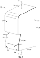
- FIG. 1 illustrates an example cover 100 according to an example of the present disclosed technology, which collectively defines an interior compartment 102 sized to receive an air conditioner.
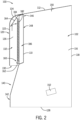
- the cover 100 includes a front wall 110, a top wall 112, a left (or first) side wall 114, and a right (or second) side wall 116 (see FIG. 2 ).
- the top wall 112 is angled downward toward the front wall 110, as may assist in shedding of water or other material.
- a rear side 118 and a bottom side 128 of the cover 100 are open (see FIG. 3 ), including as may allow air flow into or out of an air-exchange opening of an enclosure (not shown) or drainage (e.g., of condensate) out of the cover 100.
- FIG. 2 is a cross-sectional view taken along line 2-2 of FIG. 1
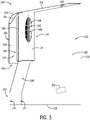
- FIG. 3 shows the example cover 100 of FIG. 1 in a sectional view so that the left side wall 114 is removed.
- a tab 150 is disposed on the top wall 112 of the cover 100 at a distance from the rear side 118 of the cover 100. In some cases, this distance may be greater than a corresponding depth of a frame of the air conditioner, as also further discussed below. Further, in the illustrated example, at least a portion of the tab 150 extends perpendicular to the angled top wall 112.
- a right (or second) side clip 152 is integrally formed or otherwise connected with the right side wall 116 of the cover 100
- a left (or first) side clip 154 is integrally formed or otherwise connected with the left side wall 114 (shown in FIG. 4 ) of the cover 100.
- An air intake opening 148 is disposed on an upper portion 146 of the front wall 110 of the cover 100.
- a shroud can be included on the front wall of, or otherwise extend from, the cover.
- a shroud 120 is disposed on the front wall 110 of the cover 100 and defines an air inlet opening 130 of the cover 100.
- the shroud 120 includes a front wall 122, a top wall 124, a right (or second) side wall 126, and a left (or first) side wall (not shown) that together define an internal shroud area 132 that provides communication between the air inlet opening 130 and the air intake opening 148.
- the shroud 120 extends over the air intake opening 148 and the air inlet opening 130 of the shroud 120 is disposed at a distance below the air intake opening 148 disposed along the front wall 110.
- a portion of the front wall below the air inlet opening can be angled.
- the front wall 110 includes a first bottom portion 140 and a second bottom portion 142 that is adjacent to the bottom side 128 of the cover 100. At least the first bottom portion 140 of the front wall 110 is angled downward from the air inlet opening 130. Further, one or more fastener holes 144 are disposed on the second bottom portion 142 of the front wall 110. In some cases, it may thus be useful for the second bottom portion 142 to extend at a different angle than the first bottom portion 140 (e.g., vertically).
- an air filter recess for filter media can be included in front of the air inlet opening and within the shroud.
- a filter recess 160 is formed by the upper portion 146 of the front wall 110 to receive and provide flow through filter media (e.g., an air filter 184, as illustrated).
- a support shelf configured as a filter bracket 162 is included at a bottom of the filter recess 160 to support the filter media relative to gravity in front of the air intake opening 148.
- Two or more filter brackets 162 can be included to secure larger air filters within the filter recess 160.
- the filter brackets 162 are formed as elbow tabs, although other configurations are possible. As also shown in FIG.
- a retention frame e.g., a grating 182 as shown
- a retention frame can be arranged adjacent to the filter bracket 162 or another support shelf to support the filter media relative to air flow from the air inlet opening 130, through the internal area of the shroud 120, and then through the air intake opening 148 and into the interior compartment 102.
- any variety of forms of a shelf can be similarly arranged to support filter media (e.g., discrete shelf sections like the brackets 162, a similarly contoured shelf that extends continuously over a larger width of the cover, an integrally bent lip of a larger front wall of a cover, etc.).
- retention frames that are differently configured than the grating 182 (e.g., different gratings, screens, louvered structures, etc.) can be similarly located in other examples to similarly support filter media relative to air flow into the interior compartment of the relevant cover.
- a filter guide 164 is disposed at an angle between the top wall 124 and the front wall 122 of the shroud 120.
- the filter guide 164 assists a user in installing the air filter 184 into the filter recess 160 and onto the filter bracket 162 within the shroud 120.
- the angled inclination of the filter guide 164 can help to direct the top of the air filter 184 appropriately inward toward the air intake opening 148, as illustrated with arrows in FIG. 2 .
- a filter guide can also be integrally formed with a cover to provide improved manufacturing efficiency and other structural advantages.
- the filter guide 164 can extend integrally from a top end of the front wall 110 of the cover 100.
- Recessed portions of a cover wall can also provide improved air flow into the interior compartment of the cover.
- the recessed upper portion 146 of the front wall 110 can provide a flow gap 186 that separates the grating 182 from the air intake opening 148.
- the flow gap 186 can be at least as wide as a distance between upstream and downstream faces of the air filter 184 as installed. As a result, more efficient air flow through the air filter 184 and into the interior compartment 102 can be achieved than may result from conventional designs.
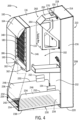
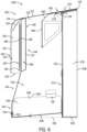
- FIGS. 4-6 show an example air conditioner 200 for an enclosure (not shown) including the example cover 100 of FIGS. 1-3 removably attached to a frame 210.
- the frame 210 includes a front wall 212, a rear wall 208, a top wall 214, a left (or first) side wall 216, a right (second) side wall 218, and a bottom wall 220 (see FIG. 4 ).
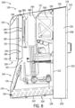
- the frame 210 can be configured to be attached to a side wall of an enclosure to surround and sealingly enclose air inlet or outlet openings for the enclosure, as well as certain equipment of the air conditioner 200 (e.g., an evaporator coil and associated fan as shown in FIG. 8 ).
- a sealing gasket e.g., gasket 222 of FIG. 8
- one or more support brackets can be connected to a frame to removably support the cover 100 or other covers according to examples of the disclosed technology.
- a bracket 260 is attached to the front wall 212 of the frame 210, adjacent to the top wall 214 of the frame 210.
- the bracket 260 includes a bracket top wall 262 that is aligned with and parallel to the top wall 214 of the frame 210.
- An opening (e.g., elongate slot) 270 is disposed on the bracket top wall 262 and is configured to receive the tab 150 of the cover 100 to removably secure the cover 100 to the frame 210.
- an opening for a tab of a cover can be disposed on the top wall 214 of the frame 210.
- use of an opening on a separate bracket may be useful in some cases, including when a frame of an air conditioner is intended to seal certain components against leakage (e.g., as shown) so that inclusion of an opening might require careful sealing arrangements.
- an air conditioner e.g., a bracket on the frame 210) can include two or more openings and a cover can include two or more corresponding tabs.
- the bracket 260 can be integrally formed with the front wall 212 of the frame 210.
- Another support bracket configured as a support tray 230 in the illustrated example, also extends from the front wall 212 and is disposed adjacent to the bottom wall 220 (see FIG. 4 ) of the frame 210.
- the support tray 230 is formed primarily from planar metal sheet segments, including a front wall 232, a left side wall 234, and a right side wall 236, and also includes a drainage grate 242 disposed on a bottom wall 238 of the support tray 230.
- the support tray 230 is integrally formed with the frame 210.
- other bracket arrangements are also possible, including with two separate side support brackets providing support structures similar to the side walls 234, 236 of the support tray 230.
- the right side clip 152 of the cover 100 is configured to mechanically (e.g., slidably) engage (e.g., seat on) a right upper interior surface 248 of the right side wall 236 of the support tray 230, as formed by a right (or second) top edge 250 of the sheet metal plate that provides the right side wall 236 in the illustrated example.
- the left side clip 154 (see FIG. 4 ) of the cover 100 is configured to mechanically (e.g., slidably) engage (e.g., seat on) a left upper surface 246 of the left side wall 234 of the support tray 230, as formed by a left (or first) top edge 252 of the sheet metal plate that provides the left side wall 234 in the illustrated example.
- side clips of a cover can extend obliquely relative to gravity or relative to a side wall of a cover.
- the clips 152, 154 extend generally linearly along planes that are obliquely angled relative to gravity and the side walls 114, 116, although obliquely directed curved clips are also possible.
- obliquely extending side clips can be easily and reliably engaged with supportive structures of a frame during installation, while providing substantial holding strength.
- obliquely angled clips can assist in alignment and reliably securement of shrouds even though operators may not have visual confirmation of the precise location of the clips or related frame structures (e.g., due to the enclosed nature of the interior compartment 102).
- two or more left side clips 154 can engage the left side wall 234 of the support tray 230 and two or more right side clips 152 can engage the right side wall 236 of the support tray 230.
- side clips of a cover may not necessarily engage a support tray or other lower support bracket when a cover is supported on an upper support bracket (e.g., the bracket 260), but may still generally extend to interior sides of side walls of the lower support bracket to prevent excessive lateral movement of the cover or to remedy (e.g., prevent or correct) excessive deformation of the relevant side walls of the cover.
- the side walls 234,236 of the support tray 230 can include one or more openings that can be configured to receive free ends of the side clips 152, 154 of the cover 100.
- the left and right side walls 216, 218 of the frame 210 can include one or more openings can be configured to receive free ends of the side clips 152, 154 of the cover 100.
- the tab 150 of the cover 100 engages the opening 270 of the frame 210 (i.e., on the bracket 260) and the left and right side clips 154, 152 of the cover 100 are slidably moved to the interior sides of the left and right side walls 234, 236 of the support tray 230 along the left and right upper surfaces 246, 248, respectively.
- the top wall 112 of the cover 100 contacts the top wall 214 of the frame 210
- the left and right side walls 114, 116 of the cover 100 contact the left and right side walls 216, 218 of the frame 210
- the front wall 110 of the cover 100 contacts the front wall 232 of the support tray 230 of the frame 210.
- the cover 100 can be securely supported against gravity at least by the support bracket 260 and the frame 210, and the tab 150 and the side clips 154, 152 can help to prevent excessive movement of the cover 100 relative to the frame 210 (e.g., in forward and lateral directions) while still allowing the cover 100 to be removed from the air conditioner 200 by being simply lifted off of the frame 210.
- fastener receivers 244 are disposed on the front wall 232 of the support tray 230 and are configured to align with the fastener holes 144 of the cover 100 when the cover 100 is removably attached to the frame 210.
- the fastener receivers 244 are threaded holes configured to receive screws 254 inserted through the fastener holes 144 to secure the front wall 110 of the cover 100 to the front wall 232 of the support tray 230 of the frame 210.
- Other fastening structures known in the art can be used to secure the cover 100 to the frame 210, including holes as formed or shaped by self-tapping screws.
- one or more fastener holes 144 of the cover 100 are disposed on the left and right side walls 114, 116 of the cover 100 and one or more fastener receivers 244 are disposed on the left and right side walls 216, 218 of the frame 210 to secure the cover 100 to the frame 210.
- FIG. 7 shows a detailed view of the tab 150 of the cover 100 engaged with the opening 270 of the bracket 260 of the frame 210.
- the bracket top wall 262 is parallel to the top wall 214 of the frame 210 and is offset from the top wall 214 of the frame 210 by a distance greater than or equal to a thickness T of an upper portion 274 of the tab 150.
- the upper portion 274 of the tab 150 may not prevent the cover 100 from sitting flushly on the top wall 214 of the frame 210.
- a lower portion 272 of the tab 150 contacts a front surface 278 of the opening 270 and, in the illustrated example, is disposed at an angle of 90 degrees relative to the upper portion 274 of the tab 150.
- the lower portion 272 of the tab 150 can help to prevent the cover 100 from sliding along the frame 210 after installation.
- the lower portion 272 of the tab 150 can be disposed at other angles relative to the upper portion 274 of the tab 150 (e.g., in a range of about 90 to 145 degrees).
- the upper portion 274 of the tab 150 can have a thickness T that is less than or greater than a thickness of the lower portion 272 of the tab 150.
- the tab 150 (or at least the lower portion 272) can be rotatably moveable relative to the top wall 112 of the cover 100.
- the tab 150 can be arranged along the cover 100 so as to be located clear of an enclosed portion of the frame 210 (e.g., as partly bounded by the top wall 214 of the frame 210, which can supportively contact the top wall 112 of the cover).
- the tab 150 can be arranged farther away from the rear side 118 of the cover 100 than a thickness of the enclosed portion of the frame 210 along the same direction.
- the opening 270 can be arranged to be clear of the enclosed portion of the frame 210 and may not need to be sealed against ingress of material into the enclosure.
- a bracket can extend forward of an enclosed portion of a frame to define an opening (e.g., a laterally elongate slot, as illustrated) to receive a tab of a cover.
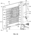
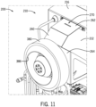
- FIGS. 8-11 illustrate another example configuration of the air conditioner 200 according to the disclosed technology.
- a flange can be arranged on an interior side of a front wall of the cover 100, so that the cover 100 can be easily and reliably installed to provide efficient air flow to cool the air conditioner 200.
- the air conditioner 200 includes a fan 380 disposed on a front surface 264 of the bracket 260.
- the fan 380 is configured to be in fluid connection with the air intake opening 148 and the air inlet opening 130 of the cover 100 when the cover 100 is removably attached to the frame 210.
- the air intake opening 148 includes an annular flange 460 extending from the front wall 110 towards the rear of the cover 100.
- the annular flange 460 can be integrally formed with or otherwise secured to the front wall 110 of the cover 100.
- the annular flange 460 is configured to be moved into alignment with an annular rim 386 (see FIG. 11 ) included on the fan 380 of the air conditioner 200, when the cover 100 is removably attached to the frame 210, to collectively define an air intake passage 390 of the air conditioner 200 (see, e.g., FIG. 8 ) that extends into the interior compartment 102 from the air intake opening 148.
- devices or systems disclosed herein can be utilized, manufactured, or installed using methods embodying aspects of the disclosed technology.
- any description herein of particular features, capabilities, or intended purposes of a device or system is generally intended to include disclosure of a method of using such devices for the intended purposes, of a method of otherwise implementing such capabilities, of a method of manufacturing relevant components of such a device or system (or the device or system as a whole), and of a method of installing disclosed (or otherwise known) components to support such purposes or capabilities.
- discussion herein of any method of manufacturing or using for a particular device or system, including installing the device or system is intended to inherently include disclosure, as examples of the disclosed technology, of the utilized features and implemented capabilities of such device or system.
- some examples can include a method by which a user can removably attach the cover 100 to the frame 210 of the air conditioner 200.
- a user With the left and right side walls 114, 116 of the cover 100 aligned with the left and right side walls 216, 218 of the frame 210, respectively, a user can lower the cover 100 onto the frame 210 towards the support tray 230 of the frame 210.
- the user While the user lowers the cover 100 onto the frame 210, the user inserts the tab 150 of the cover 100 into the opening 270 of the frame 210 and aligns the free ends of the side clips 152, 154 of the cover 100 to be located to the interior of the side walls 234, 236, respectively, of the support tray 230 of the frame 210. It should be understood that it is contemplated that the method described above can be reversed to detach the cover 100 from the frame 210 of the air conditioner 200.
- a list preceded by "one or more” (and variations thereon) and including “or” to separate listed elements indicates options of one or more of any or all of the listed elements.
- the phrases “one or more of A, B, or C" and “at least one of A, B, or C” indicate options of: one or more A; one or more B; one or more C; one or more A and one or more B; one or more B and one or more C; one or more A and one or more C; and one or more A, one or more B, and one or more C.
- a list preceded by "a plurality of' (and variations thereon) and including “or” to separate listed elements indicates options of multiple instances of any or all of the listed elements.
- phrases "a plurality of A, B, or C" and “two or more of A, B, or C” indicate options of: one or more A and one or more B; one or more B and one or more C; one or more A and one or more C; and one or more A, one or more B, and one or more C.
- integral and derivatives thereof (e.g., “integrally") describe elements that are manufactured as a single piece without fasteners, adhesive, or the like to secure separate components together.
- an element stamped, cast, or otherwise molded as a single-piece component from a single piece of sheet metal or using a single mold, without rivets, screws, or adhesive to hold separately formed pieces together is an integral (and integrally formed) element.
- an element formed from multiple pieces that are separately formed initially then later connected together is not an integral (or integrally formed) element.
Landscapes
- Engineering & Computer Science (AREA)
- Chemical & Material Sciences (AREA)
- Combustion & Propulsion (AREA)
- Mechanical Engineering (AREA)
- General Engineering & Computer Science (AREA)
- Air Filters, Heat-Exchange Apparatuses, And Housings Of Air-Conditioning Units (AREA)
Applications Claiming Priority (1)
| Application Number | Priority Date | Filing Date | Title |
|---|---|---|---|
| US202163243862P | 2021-09-14 | 2021-09-14 |
Publications (3)
| Publication Number | Publication Date |
|---|---|
| EP4148331A1 true EP4148331A1 (de) | 2023-03-15 |
| EP4148331C0 EP4148331C0 (de) | 2026-01-28 |
| EP4148331B1 EP4148331B1 (de) | 2026-01-28 |
Family
ID=83355643
Family Applications (1)
| Application Number | Title | Priority Date | Filing Date |
|---|---|---|---|
| EP22195739.2A Active EP4148331B1 (de) | 2021-09-14 | 2022-09-14 | Abdeckung für eine klimaanlage für versiegelte gehäuse |
Country Status (2)
| Country | Link |
|---|---|
| US (1) | US20230081004A1 (de) |
| EP (1) | EP4148331B1 (de) |
Families Citing this family (2)
| Publication number | Priority date | Publication date | Assignee | Title |
|---|---|---|---|---|
| CN214415871U (zh) * | 2020-12-09 | 2021-10-19 | 深圳市安拓浦科技有限公司 | 壁挂式空气净化机 |
| CN116944863A (zh) * | 2023-08-30 | 2023-10-27 | 浙江优亿医疗器械股份有限公司 | 医疗训练台车壳体安装结构的组装方法 |
Citations (5)
| Publication number | Priority date | Publication date | Assignee | Title |
|---|---|---|---|---|
| CN1880858A (zh) * | 2005-06-15 | 2006-12-20 | Lg电子株式会社 | 除湿机 |
| US20090145153A1 (en) * | 2007-12-11 | 2009-06-11 | Moynihan John P | Air conditioner cover |
| US20160102885A1 (en) * | 2014-10-10 | 2016-04-14 | Solarcity Corporation | Vent cover assembly for use with roof-mounted photovoltaic systems |
| CN110906457A (zh) * | 2019-12-31 | 2020-03-24 | 广东美的制冷设备有限公司 | 窗式空调器 |
| CN111623507A (zh) * | 2020-06-30 | 2020-09-04 | 广东美的制冷设备有限公司 | 空气消毒机的壳体及具有其的空气消毒机 |
Family Cites Families (3)
| Publication number | Priority date | Publication date | Assignee | Title |
|---|---|---|---|---|
| SE351287B (de) * | 1970-02-26 | 1972-11-20 | Svenska Flaektfabriken Ab | |
| DE102010001319A1 (de) * | 2010-01-28 | 2011-08-18 | YIT Germany GmbH, 80992 | Luftdurchlass mit einem Gehäuse sowie ein Deckensegel mit Luftdurchlass |
| DE102010016488B4 (de) * | 2010-04-16 | 2013-09-05 | Rittal Gmbh & Co. Kg | Abdeckung für eine Klimatisierungseinrichtung |
-
2022
- 2022-09-14 US US17/944,955 patent/US20230081004A1/en active Pending
- 2022-09-14 EP EP22195739.2A patent/EP4148331B1/de active Active
Patent Citations (5)
| Publication number | Priority date | Publication date | Assignee | Title |
|---|---|---|---|---|
| CN1880858A (zh) * | 2005-06-15 | 2006-12-20 | Lg电子株式会社 | 除湿机 |
| US20090145153A1 (en) * | 2007-12-11 | 2009-06-11 | Moynihan John P | Air conditioner cover |
| US20160102885A1 (en) * | 2014-10-10 | 2016-04-14 | Solarcity Corporation | Vent cover assembly for use with roof-mounted photovoltaic systems |
| CN110906457A (zh) * | 2019-12-31 | 2020-03-24 | 广东美的制冷设备有限公司 | 窗式空调器 |
| CN111623507A (zh) * | 2020-06-30 | 2020-09-04 | 广东美的制冷设备有限公司 | 空气消毒机的壳体及具有其的空气消毒机 |
Also Published As
| Publication number | Publication date |
|---|---|
| US20230081004A1 (en) | 2023-03-16 |
| EP4148331C0 (de) | 2026-01-28 |
| EP4148331B1 (de) | 2026-01-28 |
Similar Documents
| Publication | Publication Date | Title |
|---|---|---|
| US6264713B1 (en) | Media filter assembly having replaceable filter element | |
| EP4148331A1 (de) | Abdeckung für eine klimaanlage für versiegelte gehäuse | |
| US7418826B2 (en) | Low-sweat condensate pan | |
| CN112752928A (zh) | 空调 | |
| EP3118535B1 (de) | Klimaanlage | |
| US20070169494A1 (en) | Method and system for vertical coil condensate disposal | |
| US20070169501A1 (en) | Condensate pan internal corner design | |
| EP4075936A1 (de) | Klimaanlage für abgedichtete gehäuse | |
| JPH0534569B2 (de) | ||
| US10512866B2 (en) | Filter housing for filter fan | |
| US6324859B1 (en) | Indoor unit of an air conditioner | |
| US12320559B2 (en) | Interchangeable heat exchanger access panel with accessory mounting capability | |
| US20070169493A1 (en) | Condensate shield with fastener-free attachment for multi-poise furnace coils | |
| CN100594343C (zh) | 用于蒸发器单元的凝结水排水配置 | |
| SK8581Y1 (sk) | Montážne usporiadanie na upevnenie expanznej nádoby | |
| US6199393B1 (en) | Compact indoor unit of an air conditioner | |
| CN220229545U (zh) | 一种滤网模组以及风管机 | |
| EP3367008B1 (de) | Ausseneinheit für klimaanlage | |
| JP2025089563A (ja) | 室内機 | |
| CN115628476B (zh) | 室内机及空调器 | |
| KR100945627B1 (ko) | 공조기 증발기 유닛 및 팬 코일 | |
| CN100565022C (zh) | 空调的室内单元 | |
| WO2009133909A1 (ja) | 空気調和機の室内ユニット | |
| CN215109374U (zh) | 一种风冷空气压缩机箱体 | |
| CN222187295U (zh) | 接水盘组件和空气源热泵空调 |
Legal Events
| Date | Code | Title | Description |
|---|---|---|---|
| PUAI | Public reference made under article 153(3) epc to a published international application that has entered the european phase |
Free format text: ORIGINAL CODE: 0009012 |
|
| STAA | Information on the status of an ep patent application or granted ep patent |
Free format text: STATUS: THE APPLICATION HAS BEEN PUBLISHED |
|
| AK | Designated contracting states |
Kind code of ref document: A1 Designated state(s): AL AT BE BG CH CY CZ DE DK EE ES FI FR GB GR HR HU IE IS IT LI LT LU LV MC MK MT NL NO PL PT RO RS SE SI SK SM TR |
|
| STAA | Information on the status of an ep patent application or granted ep patent |
Free format text: STATUS: REQUEST FOR EXAMINATION WAS MADE |
|
| 17P | Request for examination filed |
Effective date: 20230915 |
|
| RBV | Designated contracting states (corrected) |
Designated state(s): AL AT BE BG CH CY CZ DE DK EE ES FI FR GB GR HR HU IE IS IT LI LT LU LV MC MK MT NL NO PL PT RO RS SE SI SK SM TR |
|
| STAA | Information on the status of an ep patent application or granted ep patent |
Free format text: STATUS: EXAMINATION IS IN PROGRESS |
|
| 17Q | First examination report despatched |
Effective date: 20240410 |
|
| GRAP | Despatch of communication of intention to grant a patent |
Free format text: ORIGINAL CODE: EPIDOSNIGR1 |
|
| STAA | Information on the status of an ep patent application or granted ep patent |
Free format text: STATUS: GRANT OF PATENT IS INTENDED |
|
| INTG | Intention to grant announced |
Effective date: 20250902 |
|
| GRAS | Grant fee paid |
Free format text: ORIGINAL CODE: EPIDOSNIGR3 |
|
| GRAA | (expected) grant |
Free format text: ORIGINAL CODE: 0009210 |
|
| STAA | Information on the status of an ep patent application or granted ep patent |
Free format text: STATUS: THE PATENT HAS BEEN GRANTED |
|
| AK | Designated contracting states |
Kind code of ref document: B1 Designated state(s): AL AT BE BG CH CY CZ DE DK EE ES FI FR GB GR HR HU IE IS IT LI LT LU LV MC MK MT NL NO PL PT RO RS SE SI SK SM TR |
|
| REG | Reference to a national code |
Ref country code: CH Ref legal event code: F10 Free format text: ST27 STATUS EVENT CODE: U-0-0-F10-F00 (AS PROVIDED BY THE NATIONAL OFFICE) Effective date: 20260128 Ref country code: GB Ref legal event code: FG4D |
|
| REG | Reference to a national code |
Ref country code: DE Ref legal event code: R096 Ref document number: 602022029161 Country of ref document: DE |
|
| REG | Reference to a national code |
Ref country code: IE Ref legal event code: FG4D |
|
| U01 | Request for unitary effect filed |
Effective date: 20260213 |
|
| U07 | Unitary effect registered |
Designated state(s): AT BE BG DE DK EE FI FR IT LT LU LV MT NL PT RO SE SI Effective date: 20260220 |