EP4148236A1 - Verstellanordnung für verstellschaufeln einer strömungsmaschine - Google Patents
Verstellanordnung für verstellschaufeln einer strömungsmaschine Download PDFInfo
- Publication number
- EP4148236A1 EP4148236A1 EP22192081.2A EP22192081A EP4148236A1 EP 4148236 A1 EP4148236 A1 EP 4148236A1 EP 22192081 A EP22192081 A EP 22192081A EP 4148236 A1 EP4148236 A1 EP 4148236A1
- Authority
- EP
- European Patent Office
- Prior art keywords
- lever
- adjusting
- ring
- coupling
- rod
- Prior art date
- Legal status (The legal status is an assumption and is not a legal conclusion. Google has not performed a legal analysis and makes no representation as to the accuracy of the status listed.)
- Pending
Links
- 230000008878 coupling Effects 0.000 claims abstract description 62
- 238000010168 coupling process Methods 0.000 claims abstract description 62
- 238000005859 coupling reaction Methods 0.000 claims abstract description 62
- 230000005540 biological transmission Effects 0.000 description 8
- 239000007789 gas Substances 0.000 description 8
- 238000002485 combustion reaction Methods 0.000 description 5
- 239000003350 kerosene Substances 0.000 description 2
- 238000000034 method Methods 0.000 description 2
- 239000000567 combustion gas Substances 0.000 description 1
- 230000001419 dependent effect Effects 0.000 description 1
- 239000000203 mixture Substances 0.000 description 1
- 239000000725 suspension Substances 0.000 description 1
- 238000011144 upstream manufacturing Methods 0.000 description 1
Images


Classifications
-
- F—MECHANICAL ENGINEERING; LIGHTING; HEATING; WEAPONS; BLASTING
- F01—MACHINES OR ENGINES IN GENERAL; ENGINE PLANTS IN GENERAL; STEAM ENGINES
- F01D—NON-POSITIVE DISPLACEMENT MACHINES OR ENGINES, e.g. STEAM TURBINES
- F01D17/00—Regulating or controlling by varying flow
- F01D17/10—Final actuators
- F01D17/12—Final actuators arranged in stator parts
- F01D17/14—Final actuators arranged in stator parts varying effective cross-sectional area of nozzles or guide conduits
- F01D17/16—Final actuators arranged in stator parts varying effective cross-sectional area of nozzles or guide conduits by means of nozzle vanes
- F01D17/162—Final actuators arranged in stator parts varying effective cross-sectional area of nozzles or guide conduits by means of nozzle vanes for axial flow, i.e. the vanes turning around axes which are essentially perpendicular to the rotor centre line
-
- F—MECHANICAL ENGINEERING; LIGHTING; HEATING; WEAPONS; BLASTING
- F01—MACHINES OR ENGINES IN GENERAL; ENGINE PLANTS IN GENERAL; STEAM ENGINES
- F01D—NON-POSITIVE DISPLACEMENT MACHINES OR ENGINES, e.g. STEAM TURBINES
- F01D7/00—Rotors with blades adjustable in operation; Control thereof
-
- F—MECHANICAL ENGINEERING; LIGHTING; HEATING; WEAPONS; BLASTING
- F01—MACHINES OR ENGINES IN GENERAL; ENGINE PLANTS IN GENERAL; STEAM ENGINES
- F01D—NON-POSITIVE DISPLACEMENT MACHINES OR ENGINES, e.g. STEAM TURBINES
- F01D17/00—Regulating or controlling by varying flow
- F01D17/20—Devices dealing with sensing elements or final actuators or transmitting means between them, e.g. power-assisted
-
- F—MECHANICAL ENGINEERING; LIGHTING; HEATING; WEAPONS; BLASTING
- F01—MACHINES OR ENGINES IN GENERAL; ENGINE PLANTS IN GENERAL; STEAM ENGINES
- F01D—NON-POSITIVE DISPLACEMENT MACHINES OR ENGINES, e.g. STEAM TURBINES
- F01D9/00—Stators
- F01D9/02—Nozzles; Nozzle boxes; Stator blades; Guide conduits, e.g. individual nozzles
- F01D9/04—Nozzles; Nozzle boxes; Stator blades; Guide conduits, e.g. individual nozzles forming ring or sector
- F01D9/041—Nozzles; Nozzle boxes; Stator blades; Guide conduits, e.g. individual nozzles forming ring or sector using blades
-
- F—MECHANICAL ENGINEERING; LIGHTING; HEATING; WEAPONS; BLASTING
- F02—COMBUSTION ENGINES; HOT-GAS OR COMBUSTION-PRODUCT ENGINE PLANTS
- F02C—GAS-TURBINE PLANTS; AIR INTAKES FOR JET-PROPULSION PLANTS; CONTROLLING FUEL SUPPLY IN AIR-BREATHING JET-PROPULSION PLANTS
- F02C9/00—Controlling gas-turbine plants; Controlling fuel supply in air- breathing jet-propulsion plants
- F02C9/16—Control of working fluid flow
- F02C9/20—Control of working fluid flow by throttling; by adjusting vanes
-
- F—MECHANICAL ENGINEERING; LIGHTING; HEATING; WEAPONS; BLASTING
- F04—POSITIVE - DISPLACEMENT MACHINES FOR LIQUIDS; PUMPS FOR LIQUIDS OR ELASTIC FLUIDS
- F04D—NON-POSITIVE-DISPLACEMENT PUMPS
- F04D29/00—Details, component parts, or accessories
- F04D29/40—Casings; Connections of working fluid
- F04D29/52—Casings; Connections of working fluid for axial pumps
- F04D29/54—Fluid-guiding means, e.g. diffusers
- F04D29/56—Fluid-guiding means, e.g. diffusers adjustable
- F04D29/563—Fluid-guiding means, e.g. diffusers adjustable specially adapted for elastic fluid pumps
-
- F—MECHANICAL ENGINEERING; LIGHTING; HEATING; WEAPONS; BLASTING
- F05—INDEXING SCHEMES RELATING TO ENGINES OR PUMPS IN VARIOUS SUBCLASSES OF CLASSES F01-F04
- F05D—INDEXING SCHEME FOR ASPECTS RELATING TO NON-POSITIVE-DISPLACEMENT MACHINES OR ENGINES, GAS-TURBINES OR JET-PROPULSION PLANTS
- F05D2220/00—Application
- F05D2220/30—Application in turbines
- F05D2220/32—Application in turbines in gas turbines
- F05D2220/323—Application in turbines in gas turbines for aircraft propulsion, e.g. jet engines
-
- F—MECHANICAL ENGINEERING; LIGHTING; HEATING; WEAPONS; BLASTING
- F05—INDEXING SCHEMES RELATING TO ENGINES OR PUMPS IN VARIOUS SUBCLASSES OF CLASSES F01-F04
- F05D—INDEXING SCHEME FOR ASPECTS RELATING TO NON-POSITIVE-DISPLACEMENT MACHINES OR ENGINES, GAS-TURBINES OR JET-PROPULSION PLANTS
- F05D2250/00—Geometry
- F05D2250/90—Variable geometry
-
- F—MECHANICAL ENGINEERING; LIGHTING; HEATING; WEAPONS; BLASTING
- F05—INDEXING SCHEMES RELATING TO ENGINES OR PUMPS IN VARIOUS SUBCLASSES OF CLASSES F01-F04
- F05D—INDEXING SCHEME FOR ASPECTS RELATING TO NON-POSITIVE-DISPLACEMENT MACHINES OR ENGINES, GAS-TURBINES OR JET-PROPULSION PLANTS
- F05D2260/00—Function
- F05D2260/50—Kinematic linkage, i.e. transmission of position
-
- F—MECHANICAL ENGINEERING; LIGHTING; HEATING; WEAPONS; BLASTING
- F05—INDEXING SCHEMES RELATING TO ENGINES OR PUMPS IN VARIOUS SUBCLASSES OF CLASSES F01-F04
- F05D—INDEXING SCHEME FOR ASPECTS RELATING TO NON-POSITIVE-DISPLACEMENT MACHINES OR ENGINES, GAS-TURBINES OR JET-PROPULSION PLANTS
- F05D2260/00—Function
- F05D2260/50—Kinematic linkage, i.e. transmission of position
- F05D2260/56—Kinematic linkage, i.e. transmission of position using cams or eccentrics
-
- F—MECHANICAL ENGINEERING; LIGHTING; HEATING; WEAPONS; BLASTING
- F05—INDEXING SCHEMES RELATING TO ENGINES OR PUMPS IN VARIOUS SUBCLASSES OF CLASSES F01-F04
- F05D—INDEXING SCHEME FOR ASPECTS RELATING TO NON-POSITIVE-DISPLACEMENT MACHINES OR ENGINES, GAS-TURBINES OR JET-PROPULSION PLANTS
- F05D2270/00—Control
- F05D2270/60—Control system actuates means
- F05D2270/66—Mechanical actuators
Definitions
- the present invention relates to an adjustment arrangement for adjusting adjustable vanes of a turbomachine.
- the turbomachine can, for example, be a jet engine, e.g. B. a turbofan engine. Functionally, the turbomachine is divided into compressor, combustion chamber and turbine. In the case of the jet engine, for example, the air drawn in is compressed by the compressor and burned in the downstream combustion chamber with added kerosene. The resulting hot gas, a mixture of combustion gas and air, flows through the downstream turbine and is expanded in the process.
- Both the compressor and the turbine are usually made up of several stages, each with a stator (vane ring) and a rotor (rotor blade ring).
- Blade rings with adjustable blades are used in compressors and turbines of turbomachines.
- An adjustment arrangement for adjusting the blades can include an adjustment ring, which can be rotated about a ring axis or longitudinal axis of the turbomachine, with this rotary movement then being coupled to the individual blades of the blade ring, e.g transfer the respective adjustable vane.
- the present application focuses on the upstream mechanism, namely the gear for adjusting the adjusting ring. This allows the adjustment ring to be moved in the direction of rotation, i.e. rotated a little around its ring axis.
- the present invention is based on the technical problem of specifying an advantageous adjustment arrangement for adjustable vanes of a turbomachine.
- this is achieved with the adjustment arrangement according to claim 1 .
- this has a lever and a connecting rod which couples the lever to the adjusting ring.
- a coupling rod is provided, which is used for coupling to one or more other blade rings with adjustable blades, ie can create a simultaneous adjustment across the individual stages.
- the coupling rod couples to a power arm of the lever, which is rotatably mounted at a pivot point, with its load arm being coupled to the connecting rod and thus to the adjusting ring.
- An offset, in particular an axial offset, of the coupling rod is converted via the lever into an at least partial circumferential offset of the push rod and thus a rotation of the adjusting ring.
- the coupling rod and the push rod are arranged on different sides of the lever, so that the coupling rod and the push rod do not intersect, for example when viewed radially.
- this can allow for an essentially planar arrangement of the gearing that is tangential to the adjusting ring, which can be advantageous, for example, with regard to the introduction of force and accuracy and, for example, can also reduce joint wear.
- first coupling point of the connecting rod in which it couples to the adjusting ring
- second coupling point in which the connecting rod is coupled to the lever
- these two points are on the same viewed in the radial direction, since the two rods do not cross arranged side of the coupling rod.
- the "on opposite sides of the lever" arrangement may be such that the connecting rod is located at one end of the lever and the push rod at the opposite end of the lever extends away from the lever and the connecting rod.
- the terms “axial”, “radial” and “circumferential” and the associated directions relate to the ring axis, about which the adjusting ring can be adjusted with the gear, i.e. rotated.
- This ring axis typically coincides with a longitudinal axis of the module or of the turbomachine, about which, for example, its rotor blade rings rotate during operation.
- the adjustable blades are distributed circumferentially, and several adjustable blade rings can follow one another in an axially offset manner. With the adjustment, the angle of attack of the adjustable vanes can be changed, for example as a function of the operating state of the turbomachine.
- the connecting rod is tilted by a maximum of 10° with respect to a plane spanned by the lever. Further upper limits can, for example, be at most 8°, 6°, 4° or 2°.
- the tilting of the push rod relative to the plane is preferably within a corresponding interval, also taking into account any angular deflection that may result as a result of the adjustment.
- the tilting can also be at 0° (the push rod is in the plane), at least in a zero position of the adjusting ring.
- the level spanned by the lever can contain, for example, its pivot point and the coupling points to the connecting rod and the coupling rod.
- For the tilting of the connecting rod relative to this plane is then, for example, based on a connecting straight line placed in the connecting rod, which connects its coupling points (to the adjusting ring and to the lever) with one another.
- the push rod itself can also have a curved course, but it preferably extends in a straight line.
- the coupling rod lies in a plane spanned by the lever; reference is made to the above paragraphs with regard to the definition of the plane, which is preferably combined with the essentially non-tilted push rod.
- the coupling rod lies in a plane spanned by the lever; reference is made to the above paragraphs with regard to the definition of the plane, which is preferably combined with the essentially non-tilted push rod.
- an overall straight structure can be achieved (reduced wear and increased accuracy).
- This also makes it possible, for example, to reduce an oblique load on the push or coupling rod, which could otherwise lead to a higher weight of the rod(s) or also the lever in the structural-mechanical design.
- the transmission can preferably have further levers and push rods, which are assigned to different blade rings or stages in an axially offset manner on the coupling rod.
- these levers can lie in a common plane (that is, their coupling and pivot points lie in the same plane).
- the coupling rod for connecting the rims or steps has an at least partially axial extension, preferably it is parallel to the axial direction.
- said plane, which contains the coupling rod and the lever or levers, is parallel to the axis.
- the lever or levers can, for example, also be formed with a kink or a curve, with the two coupling points and the pivot point nevertheless spanning a plane.
- the lever is an overall planar component, which more preferably also applies to the levers of the other rings or steps.
- the push rod is essentially parallel to a tangent to the adjusting ring.
- This tangent is in a first Coupling point, in which the push rod is coupled to the adjusting ring, placed on the adjusting ring.
- the push rod that is "substantially parallel" to the tangent can be tilted, for example, by a maximum of 10°, 8°, 6° or 4° relative to the tangent.
- the push rod is preferably located at a corresponding interval over the adjustment path, ie also taking into account any angular offset as a result of the adjustment. In any case, in a zero position of the adjusting ring, the angle can also be 0°.
- the first coupling point is radially spaced at most 3 cm from the adjusting ring.
- this suspension point can also be arranged, for example, on a pin protruding radially outwards on the adjusting ring and accordingly be offset a little radially outwards.
- the first coupling point is preferably as close as possible to the ring, for example offset radially outwards by a maximum of 2.5 cm, 2 cm, 1.5 cm, 1 cm or 0.5 cm in the order in which they are named, which means, for example Allow additional deformation moments to be reduced on the ring.
- At least one of the coupling points of the connecting rod is formed by a ball joint, ie the first coupling point (to the adjusting ring) and/or the second coupling point (to the lever).
- a ball joint ie the first coupling point (to the adjusting ring) and/or the second coupling point (to the lever).
- the adjustment arrangement can preferably have an actuator, in particular a linear actuator, in addition to the gear mechanism.
- This can be arranged in such a way that its adjustment path has an axial component, preferably lies parallel to the axis.
- the actuator can then preferably be coupled to one of the levers assigned to the different rings or steps, in which case the adjustment can then be transferred from this lever to the other levers with the coupling rod.
- the actuator is arranged in a preferred embodiment in such a way that, viewed in the axial direction, it is on a straight line with the lever and the connecting rod lies. This straight line is preferably tangential to the adjusting ring, compare the comments above.
- adjustment rings are provided, which are associated with axially offset blade rings (in each case for adjusting the respective adjustment blades).
- a second adjustment ring which is connected to the coupling rod via a second push rod and a second lever in such a way that the second lever converts an offset of the coupling rod, in particular an axial offset, into an offset of the second push rod, in particular a circumferential offset.
- the axially consecutive levers differ in their load arms and/or their force arms, preferably both.
- the load arm can, for example, determine how far the respective push rod and thus the respective adjusting ring is offset, with this offset being able to decrease in an adjustable compressor, for example, from axially front to axially rear.
- the power arm can be used to measure the force with which the adjustment is made and thus the torque that is applied.
- the invention also relates to a module of a turbomachine, in particular a compressor module.
- the module has a plurality of rotor blade rings, each of which is equipped with adjustable blades, which can in particular be adjustable guide blade rings.
- An adjusting ring is assigned to each adjustable vane ring, these adjusting rings being connected to one another via the transmission described here.
- the individual adjustable vanes can then preferably each be coupled to the respective adjustment ring with an adjusting lever, so that its rotational offset rotates the adjustable vanes via the lever, ie changes their angle of attack.
- the invention also relates to a turbomachine with an adjustment arrangement disclosed here or a module just mentioned, preferably an aircraft engine, particularly preferably a turbofan engine. Furthermore, the invention relates the use of an adjustment arrangement described here for adjusting adjustable adjustable vanes.
- FIG 1 shows a turbomachine 1, specifically a turbofan engine, in an axial section.
- the turbomachine 1 is functionally divided into a compressor 1a, a combustion chamber 1b and a turbine 1c. Both the compressor 1a and the turbine 1c are each constructed of multiple stages. Each of the stages consists of a ring of guide vanes 5 and a ring of rotor blades 6 .
- the reference numeral 7 designates the gas duct, ie the compressor gas duct in the case of the compressor 1a or the hot gas duct in the case of the turbine 1c.
- the intake air is compressed, it is then in the downstream combustion chamber 1b burned with added kerosene.
- the hot gas flows through the hot-gas duct and thereby drives the moving blade rings 6 which rotate about a ring axis 2 .
- ⁇ guide vane rings 5 of the compressor 1a are equipped with adjustable vanes 10, which can be adjusted to adapt the angle of attack.
- the adjustment axis, not shown here, of a respective adjustment vane 10 lies essentially radially to the ring axis 2, which coincides with a longitudinal axis of the turbomachine.
- FIG 2 shows an adjustment arrangement 20 according to the invention, with which the adjustable vanes 10 can be adjusted. It has an adjusting ring 21, with each guide vane ring 5 being assigned a respective adjusting ring 21 and these adjusting rings 21 being offset axially with respect to one another, ie spaced apart from one another in an axial direction 22.
- the adjusting rings 21 can be rotated, namely offset in the direction of rotation 26, via a gear mechanism 25, which is described in detail below.
- This rotational offset 27 of the adjusting ring 21 is transferred to the respective adjusting blade 10 via a respective lever 28 (not shown in detail), which results in the change in the flow angle described.
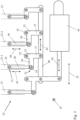
- figure 3 shows the gear 25 in a radial plan view, which in the present example is designed for the simultaneous actuation of four axially consecutive vane rings 5.
- the corresponding adjustment rings 21 are indicated by dashed lines.
- the adjustment mechanism is discussed below as an example using the second adjustment ring 21 from the left (hereinafter also "first adjustment ring 21.1”), and this applies analogously to the other adjustment rings 21.
- a push rod 30 is provided for coupling to the adjusting ring 21 , which is coupled to the adjusting ring 21 at a first coupling point 31 and to a lever 33 at a second coupling point 32 .
- the coupling points 31, 32 are each implemented via a ball joint 34.
- the lever 33 is rotatably mounted at a pivot point 35 and has a load arm 36 and a force arm 37 .
- the push rod 30 is coupled to the load arm 36, while a coupling rod 40 is coupled to the force arm 37. This extends along the axial direction 22 and connects the individual guide vane rings 5 to one another.
- An axial offset 42 can be generated by an actuator 41 and transferred to the coupling rod 40, this axial offset 42 being converted into an offset 43 of the push rod 30 by the rotatable mounting of the lever 33, as a result of which the adjusting ring 21 is rotated.
- the lever 33 is arranged between the coupling rod 40 and the push rod 30 , the latter extending away from the lever 33 , facing away from the coupling rod 40 . Accordingly, the push rod 30 is arranged completely on one side of the lever 33, both coupling points 31, 32 are in the radial view (looking at it in the radial direction 47) on the same side.
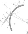
- the entire transmission 25 can thus be aligned essentially tangentially to the adjusting ring 21, compare figure 2 for illustration.
- the plane 45 spanned by the lever 33 can be seen schematically; this plane and thus the lever 33 as well as the connecting rod 30 lie essentially parallel to a tangent 46.
- a second lever 53 is also referenced as an example, which also has a load arm 56 and a force arm 57 and is rotatably mounted at a pivot point 55 .
- the second lever 53 is also connected to the coupling rod 40 and converts the axial offset 42 into an offset 58 of the second connecting rod 59 and thus of the associated adjusting ring 21 ("second adjusting ring 21.2").
- the levers 33, 53 differ in the respective dimensioning of the load arm 36, 56 and the power arm 37, 57.
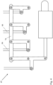
- FIG 4 shows for comparison a transmission 65 not designed according to the invention, in which the connecting rods 66 do not extend away from the coupling rod 76, but rather cross it in the radial view.
- the transmission 65 is therefore designed with a kink, which is shown in the axial view figure 5 becomes clear.
- the connecting rods 66 are deflected by an angle 77 in relation to the rest of the transmission 65, which results in an oblique introduction of force, which is prone to wear and can result in inaccuracies.
Landscapes
- Engineering & Computer Science (AREA)
- Mechanical Engineering (AREA)
- General Engineering & Computer Science (AREA)
- Chemical & Material Sciences (AREA)
- Combustion & Propulsion (AREA)
- Physics & Mathematics (AREA)
- Fluid Mechanics (AREA)
- Structures Of Non-Positive Displacement Pumps (AREA)
Abstract
Description
- Die vorliegende Erfindung betrifft eine Verstellanordnung zum Verstellen von Verstellschaufeln einer Strömungsmaschine.
- Bei der Strömungsmaschine kann es sich bspw. um ein Strahltriebwerk handeln, z. B. um ein Mantelstromtriebwerk. Funktional gliedert sich die Strömungsmaschine in Verdichter, Brennkammer und Turbine. Etwa im Falle des Strahltriebwerks wird angesaugte Luft vom Verdichter komprimiert und in der nachgelagerten Brennkammer mit hinzugemischtem Kerosin verbrannt. Das entstehende Heißgas, eine Mischung aus Verbrennungsgas und Luft, durchströmt die nachgelagerte Turbine und wird dabei expandiert. Sowohl der Verdichter als auch die Turbine ist in der Regel aus mehreren Stufen mit jeweils einem Stator (Leitschaufelkranz) und einem Rotor (Laufschaufelkranz) aufgebaut.
- Schaufelkränze mit verstellbaren Schaufeln werden in Verdichtern und Turbinen von Strömungsmaschinen benutzt. Eine Verstellanordnung zum Verstellen der Schaufeln kann einen Verstellring umfassen, der um eine Ringachse bzw. Längsachse der Strömungsmaschine drehbar ist, wobei diese Drehbewegung dann auf die einzelnen Schaufeln des Schaufelkranzes gekoppelt wird, bspw. mit umlaufend verteilten Verstellhebeln, die jeweils den Umlaufversatz des Verstellrings auf die jeweilige Verstellschaufel übertragen. Die vorliegende Anmeldung richtet sich schwerpunktmäßig auf den vorgelagerten Mechanismus, nämlich das Getriebe zum Verstellen des Verstellrings. Damit lässt sich der Verstellring in Umlaufrichtung versetzen, also ein Stück weit um seine Ringachse drehen.
- Der vorliegenden Erfindung liegt das technische Problem zugrunde, eine vorteilhafte Verstellanordnung für Verstellschaufeln einer Strömungsmaschine anzugeben.
- Dies wird erfindungsgemäß mit der Verstellanordnung gemäß Anspruch 1 gelöst. Diese weist zusätzlich zu dem Verstellring einen Hebel und eine Schubstange auf, die den Hebel an den Verstellring koppelt. Ferner ist eine Koppelstange vorgesehen, die der Kopplung an einen oder mehrere weitere Schaufelkränze mit Verstellschaufeln dient, also über die einzelnen Stufen hinweg eine simultane Verstellung schaffen kann. Die Koppelstange koppelt dabei an einen Kraftarm des in einem Drehpunkt drehbar gelagerten Hebels, wobei dessen Lastarm an die Schubstange und damit den Verstellring koppelt.
- Über den Hebel wird ein Versatz, insbesondere Axialversatz, der Koppelstange in einen zumindest anteiligen Umlaufversatz der Schubstange und damit eine Verdrehung des Verstellrings umgesetzt. Die Koppel- und die Schubstange sind dabei auf unterschiedlichen Seiten des Hebels angeordnet, sodass sich die Koppel- und die Schubstange bspw. radial betrachtet nicht kreuzen. Dies kann, wie nachstehend im Einzelnen diskutiert, eine für sich im Wesentlichen plane und dabei zum Verstellring tangentiale Anordnung des Getriebes ermöglichen, was bspw. hinsichtlich der Krafteinleitung und Genauigkeit von Vorteil sein und bspw. auch Gelenkverschleiß reduzieren kann.
- Betrachtet man einen ersten Koppelpunkt der Schubstange, in dem diese an den Verstellring koppelt, und einen zweiten Koppelpunkt, in dem die Schubstange an den Hebel gekoppelt ist, so sind diese beiden Punkte in Radialrichtung betrachtet, da die beiden Stangen sich nicht kreuzen, auf derselben Seite der Koppelstange angeordnet. Dies ermöglicht die im Wesentlichen plane Anordnung. Axial betrachtet kann die Anordnung "auf unterschiedlichen Seiten des Hebels" bspw. dahingehen, dass die Koppelstange an einem Ende des Hebels angeordnet ist und sich die Schubstange am entgegengesetzten Ende des Hebels von diesem und der Koppelstange weg erstreckt.
- Bevorzugte Ausführungsformen finden sich in den abhängigen Ansprüchen und der gesamten Offenbarung, wobei in der Darstellung der Merkmale nicht immer im Einzelnen zwischen Vorrichtungs- und Verfahrens- bzw. Verwendungsaspekten unterschieden wird; jedenfalls implizit ist die Offenbarung hinsichtlich sämtlicher Anspruchskategorien zu lesen. Ferner ist sie stets sowohl auf die Verstellanordnung als auch auf ein Modul bzw. eine Strömungsmaschine mit einer solchen Verstellanordnung zu lesen.
- Die Angaben "axial", "radial" und "umlaufend", sowie die zugehörigen Richtungen (Axialrichtung etc.) beziehen sich im Rahmen dieser Offenbarung auf die Ringachse, um welche der Verstellring mit dem Getriebe verstellbar, also drehbar ist. Diese Ringachse fällt typischerweise mit einer Längsachse des Moduls bzw. der Strömungsmaschine zusammen, um die im Betrieb bspw. dessen bzw. deren Laufschaufelkränze rotieren. Innerhalb eines jeweiligen Schaufelkranzes, insbesondere Leitschaufelkranzes, sind die Verstellschaufeln umlaufend verteilt angeordnet, und axial versetzt können mehrere verstellbare Schaufelkränze aufeinanderfolgen. Mit der Verstellung kann der Anströmwinkel der Verstellschaufeln verändert werden, bspw. in Abhängigkeit vom Betriebszustand der Strömungsmaschine.
- Gemäß einer bevorzugten Ausführungsform ist die Schubstange gegenüber einer Ebene, die der Hebel aufspannt, um den Betrag nach höchstens 10° verkippt. Weitere Obergrenzen können bspw. bei dem Betrag nach höchstens 8°, 6°, 4° bzw. 2° liegen. Bevorzugt liegt die Verkippung der Schubstange zur Ebene auch unter Berücksichtigung einer etwaigen Winkelauslenkung, die sich infolge der Verstellung ergeben kann, innerhalb eines entsprechenden Intervalls. Die Verkippung kann auch bei 0° liegen (Schubstange liegt in der Ebene), jedenfalls in einer Null-Stellung des Verstellrings. Mit der im Wesentlichen verkippungsfreien Anbindung zwischen Schubstange und Hebel kann z. B. eine vergleichsweise geradlinige Krafteinleitung erreicht werden, was den Verschleiß reduzieren und bspw. auch die Genauigkeit erhöhen kann.
- Im Einzelnen kann die von dem Hebel aufgespannte Ebene bspw. dessen Drehpunkt, sowie die Koppelpunkte zu der Schubstange und der Koppelstange beinhalten. Für die Verkippung der Schubstange gegenüber dieser Ebene wird dann bspw. eine in die Schubstange gelegte Verbindungsgerade zugrunde gelegt, die deren Koppelpunkte (zum Verstellring und zum Hebel) miteinander verbindet. Im Allgemeinen kann die Schubstange an sich also auch einen gewölbten Verlauf haben, bevorzugt erstreckt sie sich jedoch geradlinig.
- In bevorzugter Ausgestaltung liegt die Koppelstange in einer von dem Hebel aufgespannten Ebene, es wird auf die vorstehenden Absätze bezüglich der Definition der Ebene verwiesen, was bevorzugt mit der im Wesentlichen unverkippten Schubstange kombiniert ist. Damit kann bspw. in axialer Richtung betrachtet ein insgesamt geradliniger Aufbau erreicht werden (verringerter Verschleiß und erhöhte Genauigkeit). Damit lässt sich bspw. auch eine schräge Belastung der Schub- bzw. Koppelstange verringern, die anderenfalls bei der strukturmechanischen Auslegung zu einem höheren Gewicht der Stange(n) bzw. auch des Hebels führen könnte.
- Wie nachstehend im Einzelnen diskutiert, kann das Getriebe bevorzugt weitere Hebel und Schubstangen aufweisen, die an der Koppelstange axial versetzt unterschiedlichen Schaufelkränzen bzw. Stufen zugeordnet sind. Besonders bevorzugt können diese Hebel in einer gemeinsamen Ebene liegen (ihre Koppel- und Drehpunkte also in derselben Ebene liegen). Generell hat die Koppelstange zum Verbinden der Kränze bzw. Stufen eine zumindest anteilig axiale Erstreckung, bevorzugt liegt sie parallel zur Axialrichtung. Entsprechend liegt dann in bevorzugter Ausgestaltung auch besagte Ebene, welche die Koppelstange und den oder die Hebel beinhaltet, achsparallel.
- Im Allgemeinen kann der bzw. können die Hebel bspw. auch mit einem Knick oder einer Krümmung geformt sein, wobei die beiden Koppelpunkte und der Drehpunkt trotzdem eine Ebene aufspannen. In bevorzugter Ausgestaltung ist der Hebel jedoch ein insgesamt planes Bauteil, was weiter bevorzugt auch für die Hebel der anderen Kränze bzw. Stufen gilt.
- Gemäß einer bevorzugten Ausführungsform liegt die Schubstange im Wesentlichen parallel zu einer Tangente an den Verstellring. Diese Tangente wird in einem ersten Koppelpunkt, in dem die Schubstange an den Verstellring gekoppelt ist, an den Verstellring gelegt. Die zur Tangente "im Wesentlichen parallele" Schubstange kann bspw. um den Betrag nach höchstens 10°, 8°, 6° bzw. 4° gegenüber der Tangente verkippt sein. Bevorzugt liegt die Schubstange über den Verstellweg hinweg in einem entsprechenden Intervall, also auch unter Berücksichtigung eines etwaigen Winkelversatzes infolge der Verstellung. Jedenfalls in einer Null-Stellung des Verstellrings kann der Winkel auch 0° betragen.
- Gemäß einer bevorzugten Ausführungsform ist der erste Koppelpunkt radial höchstens 3 cm von dem Verstellring beabstandet. Im Allgemeinen kann dieser Aufhängungspunkt also bspw. auch an einem am Verstellring nach radial außen hervortretenden Zapfen angeordnet sein und dementsprechend ein Stück weit nach radial außen versetzt liegen. Bevorzugt liegt der erste Koppelpunkt jedoch möglichst nah am Ring, etwa um in der Reihenfolge der Nennung zunehmend bevorzugt höchstens 2,5 cm, 2 cm, 1,5 cm, 1 cm bzw. 0,5 cm nach radial außen versetzt, womit sich bspw. zusätzliche Verformungsmomente auf den Ring reduzieren lassen.
- Gemäß einer bevorzugten Ausführungsform wird zumindest einer der Koppelpunkte der Schubstange von einem Kugelgelenk gebildet, also der erste Koppelpunkt (zum Verstellring) und/oder der zweite Koppelunkt (zum Hebel). Dies kann in der kinematischen Detailgestaltung Freiheiten eröffnen, wobei die "geradlinige" Belastung der Kugelgelenke, die sich aus dem vorliegenden Gegenstand ergibt, deren Verschleiß reduzieren kann.
- Generell kann die Verstellanordnung zusätzlich zu dem Getriebe bevorzugt einen Aktor aufweisen, insbesondere einen Linearaktor. Dieser kann derart angeordnet sein, dass sein Verstellweg eine Axialkomponente hat, bevorzugt achsparallel liegt. Der Aktor kann dann bevorzugt an einen der den unterschiedlichen Kränzen bzw. Stufen zugeordneten Hebel koppeln, wobei die Verstellung von diesem Hebel auf die anderen Hebel dann mit der Koppelstange übertragen werden kann. Unabhängig von diesen Details ist der Aktor in bevorzugter Ausgestaltung derart angeordnet, dass er in axialer Richtung betrachtet mit dem Hebel und der Schubstange auf einer Geraden liegt. Diese Gerade liegt bevorzugt tangential zum Verstellring, vergleiche die vorstehenden Anmerkungen.
- Wie bereits erwähnt, sind in bevorzugter Ausgestaltung mehrere Verstellringe vorgesehen, die axial versetzten Schaufelkränzen zugeordnet sind (jeweils zum Verstellen der jeweiligen Verstellschaufeln). Konkret kann es also einen zweiten Verstellring geben, der über eine zweite Schubstange und einen zweiten Hebel mit der Koppelstange derart verbunden ist, dass der zweite Hebel einen Versatz der Koppelstange, insbesondere einen Axialversatz, in einen Versatz der zweiten Schubstange umsetzt, insbesondere einen Umlaufversatz.
- Gemäß einer bevorzugten Ausführungsform unterscheiden sich die axial aufeinanderfolgenden Hebel in ihren Lastarmen und/oder ihren Kraftarmen, bevorzugt beides. Der Lastarm kann bspw. bestimmen, wie weit die jeweilige Schubstange und damit der jeweiligen Verstellring versetzt wird, wobei dieser Versatz in einem verstellbaren Verdichter bspw. von axial vorne nach axial hinten abnehmen kann. Über den Kraftarm kann sich bemessen, mit welcher Kraft verstellt und damit welches Drehmoment aufgebracht wird.
- Die Erfindung betrifft auch ein Modul einer Strömungsmaschine, insbesondere ein Verdichtermodul. Das Modul weist mehrere Laufschaufelkränze auf, die jeweils mit verstellbaren Schaufeln ausgestattet sind, wobei es sich insbesondere um verstellbare Leitschaufelkränze handeln kann. Jedem verstellbaren Schaufelkranz ist dabei ein Verstellring zugeordnet, wobei diese Verstellringe über das vorliegend beschriebenen Getriebe miteinander verbunden sind. Die einzelnen Verstellschaufeln können dann bevorzugt jeweils mit einem Verstellhebel an den jeweiligen Verstellring koppeln, sodass dessen Drehversatz über die Hebel die Verstellschaufeln verdreht, also deren Anströmwinkel ändert.
- Die Erfindung betrifft auch eine Strömungsmaschine mit einer vorliegend offenbarten Verstellanordnung bzw. einem eben erwähnten Modul, bevorzugt ein Flugtriebwerk, besonders bevorzugt ein Mantelstromtriebwerk. Ferner betrifft die Erfindung die Verwendung einer vorliegend beschriebenen Verstellanordnung zum Verstellen von verstellbaren Verstellschaufeln.
- Im Folgenden wird die Erfindung anhand eines Ausführungsbeispiels näher erläutert, wobei die einzelnen Merkmale im Rahmen der nebengeordneten Ansprüche auch in anderer Kombination erfindungswesentlich sein können und auch weiterhin nicht im Einzelnen zwischen den unterschiedlichen Anspruchskategorien unterschieden wird.
- Im Einzelnen zeigt
- Figur 1
- eine Strömungsmaschine, nämlich ein Flugtriebwerk in einem Axialschnitt;
- Figur 2
- eine erfindungsgemäße Verstellanordnung in einer Axialansicht;
- Figur 3
- einen Teil der Verstellanordnung gemäß
Figur 2 in einer Radialansicht; - Figur 4
- zum Vergleich eine nicht erfindungsgemäße Anordnung mit sich kreuzenden Koppel- und Schubstangen;
- Figur 5
- die nicht erfindungsgemäße Anordnung gemäß
Figur 4 in einer Axialansicht. -
Figur 1 zeigt eine Strömungsmaschine 1, konkret ein Mantelstromtriebwerk, in einem Axialschnitt. Die Strömungsmaschine 1 gliedert sich funktional in Verdichter 1a, Brennkammer 1b und Turbine 1c. Sowohl der Verdichter 1a als auch die Turbine 1c sind jeweils aus mehreren Stufen aufgebaut. Jede der Stufen setzt sich aus einem Leitschaufelkranz 5 und einem Laufschaufelkranz 6 zusammen. Das Bezugszeichen 7 bezeichnet den Gaskanal, also den Verdichtergaskanal im Falle des Verdichters 1a bzw. den Heißgaskanal im Falle der Turbine 1c. Im Verdichtergaskanal wird die angesaugte Luft komprimiert, sie wird dann in der nachgelagerten Brennkammer 1b mit hinzugemischten Kerosin verbrannt. Das Heißgas durchströmt den Heißgaskanal und treibt dabei die Laufschaufelkränze 6 an, die um eine Ringachse 2 rotieren. - Im vorliegenden Beispiel sind mehrere Leitschaufelkränze 5 des Verdichters 1a mit Verstellschaufeln 10 ausgestattet, diese lassen sich zur Anpassung des Anströmwinkels verstellen. Die hier nicht gezeigte Verstellachse einer jeweiligen Verstellschaufel 10 liegt dabei jeweils im Wesentlichen radial zur Ringachse 2, die mit einer Längsachse der Strömungsmaschine zusammenfällt.
-
Figur 2 zeigt eine erfindungsgemäße Verstellanordnung 20, mit der sich die Verstellschaufeln 10 verstellen lassen. Sie weist einen Verstellring 21 auf, wobei jedem Leitschaufelkranz 5 ein jeweiliger Verstellring 21 zugeordnet ist und diese Verstellringe 21 axial zueinander versetzt sind, also in einer Axialrichtung 22 zueinander beabstandet. Über ein nachstehend im Detail geschildertes Getriebe 25 können die Verstellringe 21 verdreht, nämlich in Umlaufrichtung 26 versetzt werden. Dieser Umlaufversatz 27 des Verstellrings 21 wird über einen jeweiligen Hebel 28 auf die jeweilige Verstellschaufel 10 übertragen (nicht im Einzelnen dargestellt), was die geschilderte Veränderung des Anströmwinkels ergibt. -
Figur 3 zeigt in einer radialen Aufsicht das Getriebe 25, das im vorliegenden Beispiel zur simultanen Betätigung von vier axial aufeinanderfolgenden Leitschaufelkränzen 5 ausgelegt ist. Die entsprechenden Verstellringe 21 sind strichliert angedeutet. Der Verstellmechanismus wird im Folgenden exemplarisch anhand des zweiten Verstellrings 21 von links diskutiert (nachfolgend auch "erster Verstellring 21.1"), für die anderen Verstellringe 21 gilt dies analog. Zur Kopplung an den Verstellring 21 ist eine Schubstange 30 vorgesehen, die in einem ersten Koppelpunkt 31 an den Verstellring 21 und in einem zweiten Koppelpunkt 32 an einen Hebel 33 koppelt. Die Koppelpunkte 31, 32 sind dabei jeweils über ein Kugelgelenk 34 realisiert. - Der Hebel 33 ist in einem Drehpunkt 35 drehbar gelagert und weist einen Lastarm 36 sowie einen Kraftarm 37 auf. An den Lastarm 36 ist die Schubstange 30 gekoppelt, an den Kraftarm 37 hingegen eine Koppelstange 40. Diese erstreckt sich entlang der Axialrichtung 22 und verbindet die einzelnen Leitschaufelkränze 5 miteinander. Mit einem Aktor 41 lässt sich ein Axialversatz 42 erzeugen und auf die Koppelstange 40 übertragen, wobei dieser Axialversatz 42 durch die drehbare Lagerung des Hebels 33 in einen Versatz 43 der Schubstange 30 umgesetzt wird, infolgedessen also der Verstellring 21 verdreht wird.
- Der Hebel 33 ist zwischen der Koppelstange 40 und der Schubstange 30 angeordnet, letztere erstreckt sich der Koppelstange 40 abgewandt vom Hebel 33 weg. Dementsprechend ist die Schubstange 30 vollständig auf einer Seite des Hebels 33 angeordnet, beide Koppelpunkte 31, 32 liegen in der Radialansicht (in Radialrichtung 47 darauf blickend) auf derselben Seite. Dies erlaubt eine insgesamt plane Anordnung der Schubstange 30, des Hebels 33 und der Koppelstange 40. Das gesamte Getriebe 25 lässt sich damit im Wesentlichen tangential zum Verstellring 21 ausrichten, vergleiche
Figur 2 zur Illustration. Dort ist die vom Hebel 33 aufgespannte Ebene 45 schematisch zu erkennen, diese und damit der Hebel 33 sowie auch die Schubstange 30 liegen im Wesentlichen parallel zu einer Tangente 46. - Exemplarisch ist ferner ein zweiter Hebel 53 referenziert, der ebenfalls einen Lastarm 56 sowie einen Kraftarm 57 aufweist und in einem Drehpunkt 55 drehbar gelagert ist. Der zweite Hebel 53 ist ebenfalls mit der Koppelstange 40 verbunden und setzt den Axialversatz 42 in einen Versatz 58 der zweiten Schubstange 59 und damit des zugeordneten Verstellrings 21 um ("zweiter Verstellring 21.2"). Die Hebel 33, 53 unterscheiden sich dabei in der jeweiligen Bemessung von Lastarm 36, 56 und Kraftarm 37, 57.
-
Figur 4 zeigt zum Vergleich ein nicht erfindungsgemäß gestaltetes Getriebe 65, bei dem sich die Schubstangen 66 nicht von der Koppelstange 76 weg erstrecken, sondern diese in der Radialansicht kreuzen. Das Getriebe 65 ist deshalb mit einem Knick ausgeführt, was in der Axialansicht gemäßFigur 5 deutlich wird. Die Schubstangen 66 sind gegenüber dem übrigen Getriebe 65 um einen Winkel 77 ausgelenkt, was eine schräge Krafteinleitung ergibt, die verschleißträchtig ist und Ungenauigkeiten zur Folge haben kann.BEZUGSZEICHENLISTE Strömungsmaschine 1 Verdichter 1a Brennkammer 1b Turbine 1c Ringachse 2 Schaufelkranz (Leitschaufelkranz) 5 Laufschaufelkranz 6 Gaskanal 7 Verstellschaufel 10 Verstellanordnung 20 Verstellringe 21 Erster Verstellring 21.1 Zweiter Verstellring 21.2 Axialrichtung 22 Umlaufrichtung 26 Umlaufversatz 27 Getriebe 25 Verstellhebel 28 Schubstange 30, 54 Koppelpunkt 31, 32 Hebel 33 Kugelgelenk 34 Lastarm 36, 56 Kraftarm 37, 57 Koppelstange 40 Aktor 41 Axialversatz 42 Versatz (Schubstange) 43 Aufgespannte Ebene 45 Tangente 46 Radialrichtung 47 Hebel 53 Drehpunkt 55 Versatz 58 Schubstange 59 Getriebe 65 Schubstange 66 Koppelstange 76 Winkel 77
Claims (13)
- Verstellanordnung (20) zum Verstellen von Verstellschaufeln (10) einer Strömungsmaschine (1), miteinem Verstellring (21) zur Kopplung an die Verstellschaufeln (10) eines Schaufelkranzes (5), undeinem Getriebe (25), welches eine Koppelstange (40) zur Kopplung an einen weiteren Schaufelkranz (5), sowie einen Hebel (33) und eine Schubstange (30) aufweist,wobei der Hebel (33) in einem Drehpunkt (35) drehbar gelagert ist und einen Lastarm (36) sowie einen Kraftarm (37) aufweist,wobei der Lastarm (36) des Hebels (33) an die Schubstange (30) und sein Kraftarm (37) an die Koppelstange (40) gekoppelt ist, sodass ein Versatz (42) der Koppelstange (40) über den Hebel (33) und die Schubstange (30) in eine Drehung des Verstellrings (21) um dessen Ringachse (2) umgesetzt wird,und wobei die Koppelstange (40) und die Schubstange (30) auf unterschiedlichen Seiten des Hebels (33) angeordnet sind.
- Verstellanordnung (20) nach Anspruch 1, bei welcher die Schubstange (30) gegenüber einer von dem Hebel (33) aufgespannten Ebene (45) um den Betrag nach höchstens 10° verkippt ist.
- Verstellanordnung (20) nach Anspruch 1 oder 2, bei welcher die Koppelstange (40) in einer von dem Hebel (33) aufgespannten Ebene (45) liegt.
- Verstellanordnung (20) nach einem der vorstehenden Ansprüche, bei welcher der Hebel (33) ein insgesamt planes Bauteil ist.
- Verstellanordnung (20) nach einem der vorstehenden Ansprüche, bei welcher die Schubstange (30) zu einer Tangente (46), die in einem ersten Koppelpunkt (31), in dem die Schubstange (30) an den Verstellring (21) gekoppelt ist, an den Verstellring (21) gelegt wird, um den Betrag nach höchstens 10° verkippt ist.
- Verstellanordnung (20) nach einem der vorstehenden Ansprüche, bei welcher ein erster Koppelpunkt (31), in dem die Schubstange (30) an den Verstellring (21) gekoppelt ist, um radial höchstens 3 cm von dem Verstellring (21) beabstandet ist.
- Verstellanordnung (20) nach einem der vorstehenden Ansprüche, bei welcher die Schubstange (30) in einem ersten Koppelpunkt (31) an den Verstellring (21) gekoppelt ist und in einem zweiten Koppelpunkt (32) an den Hebel (33) gekoppelt ist, wobei zumindest einer der Koppelpunkte (31, 32) von einem Kugelgelenk (34) gebildet wird.
- Verstellanordnung (20) nach einem der vorstehenden Ansprüche, mit einem Aktor (41) zum Verstellen des Hebels (33) und der Schubstange (30), wobei der Aktor (41), der Hebel (33) und die Schubstange (30) axial betrachtet auf einer Geraden liegen.
- Verstellanordnung (20) nach einem der vorstehenden Ansprüche, mit einem zweiten Verstellring (21.2), der zur Kopplung an Verstellschaufeln (10) eines weiteren Schaufelkranzes (5) vorgesehen ist, wobei die Verstellringe (21, 21.2) axial versetzt sind und die Koppelstange (40) die axial versetzten Verstellringe (21, 21.2) miteinander koppelt.
- Verstellanordnung (20) nach Anspruch 9, bei welcher der zweite Verstellring (21.2) über eine zweite Schubstange (54) und einen zweiten Hebel (53) mit der Koppelstange (40) verbunden ist, wobei der zweite Hebel (53) in einem Drehpunkt (55) drehbar gelagert ist und einen Lastarm (56) sowie einen Kraftarm (57) aufweist, wobei sich der Lastarm (56) und/oder der Kraftarm (57) des zweiten Hebels (53) von dem ersten Hebel (33) unterscheiden.
- Modul (1a, 1b) mit Leitschaufelkränzen (5), die jeweils verstellbare Verstellschaufeln (10) aufweisen, und mit einer Verstellanordnung (20) nach Anspruch 9 oder 10, wobei die Verstellschaufeln (10) eines jeweiligen Leitschaufelkranzes (5) jeweils über einen Verstellhebel (28) an einen jeweiligen Verstellring (21) gekoppelt sind.
- Strömungsmaschine (1), insbesondere Flugtriebwerk, mit einer Verstellanordnung (20) nach einem der Ansprüche 1 bis 10 oder einem Modul nach Anspruch 11.
- Verwendung einer Verstellanordnung (20) nach einem der Ansprüche 1 bis 10 oder eines Moduls (1a, 1b) nach Anspruch 11 oder einer Strömungsmaschine (1) nach Anspruch 12 zum Verstellen von verstellbaren Verstellschaufeln (10).
Applications Claiming Priority (1)
| Application Number | Priority Date | Filing Date | Title |
|---|---|---|---|
| DE102021123772.6A DE102021123772A1 (de) | 2021-09-14 | 2021-09-14 | Verstellanordnung für verstellschaufeln einer strömungsmaschine |
Publications (1)
| Publication Number | Publication Date |
|---|---|
| EP4148236A1 true EP4148236A1 (de) | 2023-03-15 |
Family
ID=83081333
Family Applications (1)
| Application Number | Title | Priority Date | Filing Date |
|---|---|---|---|
| EP22192081.2A Pending EP4148236A1 (de) | 2021-09-14 | 2022-08-25 | Verstellanordnung für verstellschaufeln einer strömungsmaschine |
Country Status (3)
| Country | Link |
|---|---|
| US (1) | US11891918B2 (de) |
| EP (1) | EP4148236A1 (de) |
| DE (1) | DE102021123772A1 (de) |
Families Citing this family (1)
| Publication number | Priority date | Publication date | Assignee | Title |
|---|---|---|---|---|
| DE102023112223A1 (de) | 2023-05-10 | 2024-11-14 | MTU Aero Engines AG | Kupplungsvorrichtung zum Verbinden von zwei Wellen, Verstellsystem zur Verstellung von variablen Verdichterstufen eines Axialverdichters einer Strömungsmaschine, Axialverdichter für eine Strömungsmaschine, sowie Strömungsmaschine |
Citations (7)
| Publication number | Priority date | Publication date | Assignee | Title |
|---|---|---|---|---|
| US2858062A (en) * | 1955-01-24 | 1958-10-28 | Gen Electric | Variable stator mechanism |
| FR1246176A (fr) * | 1959-01-03 | 1960-11-18 | Entwicklungsbau Pirna Veb | Compresseur axial |
| US2999630A (en) * | 1957-08-08 | 1961-09-12 | Gen Electric | Compressor |
| US5692879A (en) * | 1995-09-27 | 1997-12-02 | Societe Nationale D'etude Et De Construction De Moteurs D'aviation Snecma | Control device for a stage of blades with variable pitch |
| US6398483B1 (en) * | 1999-06-10 | 2002-06-04 | Snecma Moteurs | Protection device for protecting control mechanism of inlet guide-vanes of turbojet engine |
| US20050129510A1 (en) * | 2003-06-20 | 2005-06-16 | Snecma Moteurs | Variable pitch device for two blade stages fixed onto a turbojet |
| EP1724471A2 (de) * | 2005-05-17 | 2006-11-22 | Snecma | Kontrollsystem für verstellbaren Statorschaufelstufen einer Turbomaschine |
Family Cites Families (10)
| Publication number | Priority date | Publication date | Assignee | Title |
|---|---|---|---|---|
| US2933234A (en) * | 1954-12-28 | 1960-04-19 | Gen Electric | Compressor stator assembly |
| US3861822A (en) | 1974-02-27 | 1975-01-21 | Gen Electric | Duct with vanes having selectively variable pitch |
| US3873230A (en) | 1974-04-10 | 1975-03-25 | United Aircraft Corp | Stator vane actuating mechanism |
| US4295784A (en) | 1979-09-26 | 1981-10-20 | United Technologies Corporation | Variable stator |
| US4720237A (en) | 1986-02-24 | 1988-01-19 | United Technologies Corporation | Unison ring actuator assembly |
| JPH0219698A (ja) * | 1988-07-07 | 1990-01-23 | Hitachi Ltd | ベーンコントロール装置 |
| DE3913102C1 (de) | 1989-04-21 | 1990-05-31 | Mtu Muenchen Gmbh | |
| US9394804B2 (en) * | 2012-01-24 | 2016-07-19 | Florida Institute Of Technology | Apparatus and method for rotating fluid controlling vanes in small turbine engines and other applications |
| DE102016212767A1 (de) | 2016-07-13 | 2018-01-18 | MTU Aero Engines AG | Verstellbares Turbomaschinen-Schaufelgitter |
| US11105219B2 (en) | 2019-07-03 | 2021-08-31 | Raytheon Technologies Corporation | Vane angle system accuracy improvement |
-
2021
- 2021-09-14 DE DE102021123772.6A patent/DE102021123772A1/de active Pending
-
2022
- 2022-08-25 EP EP22192081.2A patent/EP4148236A1/de active Pending
- 2022-09-12 US US17/931,345 patent/US11891918B2/en active Active
Patent Citations (7)
| Publication number | Priority date | Publication date | Assignee | Title |
|---|---|---|---|---|
| US2858062A (en) * | 1955-01-24 | 1958-10-28 | Gen Electric | Variable stator mechanism |
| US2999630A (en) * | 1957-08-08 | 1961-09-12 | Gen Electric | Compressor |
| FR1246176A (fr) * | 1959-01-03 | 1960-11-18 | Entwicklungsbau Pirna Veb | Compresseur axial |
| US5692879A (en) * | 1995-09-27 | 1997-12-02 | Societe Nationale D'etude Et De Construction De Moteurs D'aviation Snecma | Control device for a stage of blades with variable pitch |
| US6398483B1 (en) * | 1999-06-10 | 2002-06-04 | Snecma Moteurs | Protection device for protecting control mechanism of inlet guide-vanes of turbojet engine |
| US20050129510A1 (en) * | 2003-06-20 | 2005-06-16 | Snecma Moteurs | Variable pitch device for two blade stages fixed onto a turbojet |
| EP1724471A2 (de) * | 2005-05-17 | 2006-11-22 | Snecma | Kontrollsystem für verstellbaren Statorschaufelstufen einer Turbomaschine |
Also Published As
| Publication number | Publication date |
|---|---|
| DE102021123772A1 (de) | 2023-03-16 |
| US11891918B2 (en) | 2024-02-06 |
| US20230077444A1 (en) | 2023-03-16 |
Similar Documents
| Publication | Publication Date | Title |
|---|---|---|
| EP3283733B1 (de) | Leitschaufelverstellvorrichtung und strömungsmaschine | |
| EP3283732B1 (de) | Leitschaufelverstellvorrichtung und strömungsmaschine | |
| EP3269941B1 (de) | Verstellbares schaufelgitter für eine turbomaschine | |
| CH702692B1 (de) | Variable Leitschaufel und Verfahren zur Beseitigung einer aerodynamischen Erregung. | |
| DE102014104318A1 (de) | Strömungsmanipulationsanordnung für einen Turbinenauslassdiffusor | |
| EP2650490A2 (de) | Leitschaufelverstellvorrichtung einer Gasturbine | |
| DE102011000143A1 (de) | Verfahren und Einrichtung für eine segmentierte Turbinenschaufelanordnung | |
| DE102019200885A1 (de) | Leitgitter für eine Strömungsmaschine | |
| CH709266B1 (de) | Turbinenschaufel und Verfahren zum Auswuchten eines Spitzendeckbandes einer Turbinenschaufel und Gasturbine. | |
| DE102007050916A1 (de) | Verfahren und Vorrichtung zum Zusammenbau von Gasturbinen-Triebwerken | |
| EP1624192A1 (de) | Verdichterschaufel für einen Verdichter und Verdichter | |
| EP2730751B1 (de) | Leitschaufelverstellvorrichtung einer Gasturbine | |
| EP4148236A1 (de) | Verstellanordnung für verstellschaufeln einer strömungsmaschine | |
| EP3176386B1 (de) | Innenringsystem, zugehöriger innenring, zwichengehäuse und strömungsmaschine | |
| EP4230846B1 (de) | Hebel zum verstellen einer verstellschaufel | |
| WO2022128354A1 (de) | Schaufelbauteil, verfahren zu dessen herstellung und gasturbine | |
| WO2005045202A1 (de) | Vorrichtung zum verstellen von leitschaufeln eines turbotriebwerks | |
| DE10352789B4 (de) | Gasturbine | |
| DE102011052037A1 (de) | Strömungsteileranordnung für Dampfturboantrieb und Verfahren | |
| DE19909899A1 (de) | Schaufeln mit veränderbarer Profilgeometrie | |
| EP3219921B1 (de) | Verstellbare turbomaschinen-leitschaufel, turbomaschine und verfahren zum herstellen | |
| DE102004026365B4 (de) | Einrichtung zur Unwuchtkompensation | |
| DE102022112652A1 (de) | Vorrichtung zum synchronen Verstellen einer Vielzahl von variablen Verdichterstufen für einen Axialverdichter einer Strömungsmaschine, sowie eine Strömungsmaschine | |
| EP3636880A1 (de) | Turbinenrad | |
| DE102023127736A1 (de) | Leitschaufelverstellvorrichtung und Strömungsmaschine |
Legal Events
| Date | Code | Title | Description |
|---|---|---|---|
| PUAI | Public reference made under article 153(3) epc to a published international application that has entered the european phase |
Free format text: ORIGINAL CODE: 0009012 |
|
| STAA | Information on the status of an ep patent application or granted ep patent |
Free format text: STATUS: THE APPLICATION HAS BEEN PUBLISHED |
|
| AK | Designated contracting states |
Kind code of ref document: A1 Designated state(s): AL AT BE BG CH CY CZ DE DK EE ES FI FR GB GR HR HU IE IS IT LI LT LU LV MC MK MT NL NO PL PT RO RS SE SI SK SM TR |
|
| STAA | Information on the status of an ep patent application or granted ep patent |
Free format text: STATUS: REQUEST FOR EXAMINATION WAS MADE |
|
| 17P | Request for examination filed |
Effective date: 20230915 |
|
| RBV | Designated contracting states (corrected) |
Designated state(s): AL AT BE BG CH CY CZ DE DK EE ES FI FR GB GR HR HU IE IS IT LI LT LU LV MC MK MT NL NO PL PT RO RS SE SI SK SM TR |
|
| STAA | Information on the status of an ep patent application or granted ep patent |
Free format text: STATUS: EXAMINATION IS IN PROGRESS |
|
| 17Q | First examination report despatched |
Effective date: 20250102 |