EP4148223B1 - Federbelastete türschwelle - Google Patents
Federbelastete türschwelle Download PDFInfo
- Publication number
- EP4148223B1 EP4148223B1 EP21195645.3A EP21195645A EP4148223B1 EP 4148223 B1 EP4148223 B1 EP 4148223B1 EP 21195645 A EP21195645 A EP 21195645A EP 4148223 B1 EP4148223 B1 EP 4148223B1
- Authority
- EP
- European Patent Office
- Prior art keywords
- ramp
- ramp member
- door threshold
- floor
- link
- Prior art date
- Legal status (The legal status is an assumption and is not a legal conclusion. Google has not performed a legal analysis and makes no representation as to the accuracy of the status listed.)
- Active
Links
Images


Classifications
-
- E—FIXED CONSTRUCTIONS
- E06—DOORS, WINDOWS, SHUTTERS, OR ROLLER BLINDS IN GENERAL; LADDERS
- E06B—FIXED OR MOVABLE CLOSURES FOR OPENINGS IN BUILDINGS, VEHICLES, FENCES OR LIKE ENCLOSURES IN GENERAL, e.g. DOORS, WINDOWS, BLINDS, GATES
- E06B1/00—Border constructions of openings in walls, floors, or ceilings; Frames to be rigidly mounted in such openings
- E06B1/70—Sills; Thresholds
-
- E—FIXED CONSTRUCTIONS
- E06—DOORS, WINDOWS, SHUTTERS, OR ROLLER BLINDS IN GENERAL; LADDERS
- E06B—FIXED OR MOVABLE CLOSURES FOR OPENINGS IN BUILDINGS, VEHICLES, FENCES OR LIKE ENCLOSURES IN GENERAL, e.g. DOORS, WINDOWS, BLINDS, GATES
- E06B7/00—Special arrangements or measures in connection with doors or windows
- E06B7/16—Sealing arrangements on wings or parts co-operating with the wings
- E06B7/18—Sealing arrangements on wings or parts co-operating with the wings by means of movable edgings, e.g. draught sealings additionally used for bolting, e.g. by spring force or with operating lever
- E06B7/20—Sealing arrangements on wings or parts co-operating with the wings by means of movable edgings, e.g. draught sealings additionally used for bolting, e.g. by spring force or with operating lever automatically withdrawn when the wing is opened, e.g. by means of magnetic attraction, a pin or an inclined surface, especially for sills
-
- E—FIXED CONSTRUCTIONS
- E06—DOORS, WINDOWS, SHUTTERS, OR ROLLER BLINDS IN GENERAL; LADDERS
- E06B—FIXED OR MOVABLE CLOSURES FOR OPENINGS IN BUILDINGS, VEHICLES, FENCES OR LIKE ENCLOSURES IN GENERAL, e.g. DOORS, WINDOWS, BLINDS, GATES
- E06B7/00—Special arrangements or measures in connection with doors or windows
- E06B7/16—Sealing arrangements on wings or parts co-operating with the wings
- E06B7/18—Sealing arrangements on wings or parts co-operating with the wings by means of movable edgings, e.g. draught sealings additionally used for bolting, e.g. by spring force or with operating lever
- E06B7/20—Sealing arrangements on wings or parts co-operating with the wings by means of movable edgings, e.g. draught sealings additionally used for bolting, e.g. by spring force or with operating lever automatically withdrawn when the wing is opened, e.g. by means of magnetic attraction, a pin or an inclined surface, especially for sills
- E06B7/205—Sealing arrangements on wings or parts co-operating with the wings by means of movable edgings, e.g. draught sealings additionally used for bolting, e.g. by spring force or with operating lever automatically withdrawn when the wing is opened, e.g. by means of magnetic attraction, a pin or an inclined surface, especially for sills with sealing strip mounted on sill
Definitions
- the present disclosure relates to a door threshold, and especially to a door threshold being moveable between two positions.
- a standard threshold for a door has an appearance adapted to function based on the requirements that apply regarding, among other things, sealing and fire requirements.
- the edge that exists to meet these requirements is unfortunately an obstacle for wheelchair users.
- the society should be accessible to all. Regardless of functional ability, it must be possible to be involved in society. There may be regulations on easily remedied obstacles in the built environment that states that entrances, balconies, terraces and patios must be accessible, which means that they should be designed without level differences, unless there is a need for a threshold for humidity or climate reasons. However, this should be as low as possible and be phased. Moisture safety has historically largely been handled at openings in a building with the help of level differences between the wet and the dry side. The issue of accessibility means in these situations that the possibility of level differences is limited, i.e. opportunities for threshold and plinth, which gives a built-in conflict in the design of the building.
- the solution needs to be adapted for requirements and directives; adapted for passage with a wheelchair; and adjustable to be able to mount the threshold regardless of conditions.
- the provided solution may meet the requirements to function as a standard threshold in its basic position and then be converted into a solution adapted for wheelchairs when a wheelchair is to pass.
- a door threshold for arrangement below a door at a doorway wherein the doorway is located between a first floor or ground surface and a second floor or ground surface, the first floor or ground surface having a height difference to the second floor or ground surface.
- the door threshold comprises a bottom member configured to, when in use, be arranged on a horizontal bottom surface of the doorway; a first ramp member configured to, at a first end of the first ramp member, when in use, be in contact with the first floor or ground surface; a second ramp member configured to, when in use, extend from the bottom member towards the second floor or ground surface; a spring member in a first end attached to the bottom member; and a link member in a first end rotatably attached to a second end of the first ramp member and in a second end connected to a second end of the spring member.
- the spring member provides a biasing force to the first ramp member towards a resting state, and when a force is applied on the first ramp member, the first ramp member moves towards a down pressed position by rotating around the first end of the first ramp member.
- the first ramp member may extend from the first floor or ground surface towards a door in the doorway, when the door is closed.
- the first ramp member may then extend in as an upward sloping ramp towards the door.
- the closed door may then be closed to, or adjacent to, the upward end of the first ramp member.
- the second ramp member may extend towards the second floor or ground surface.
- the height difference between the first and second floor or ground surfaces may be provided in the doorway such that the first floor or ground surface may be arranged higher than the second floor or ground surface.
- the first floor or ground surface may be at an inside of a house or room, and the second floor or ground surface may at an outside of a house or room.
- the door threshold In the resting position, when nothing or no one passes through the doorway, the door threshold may provide the function of a standard door threshold in terms of fulfilling the requirements of e.g. sealing at a doorway.
- the first ramp member When someone passes the doorway, either by foot, wheelchair or other equipment, the first ramp member may be pressed downward to a down pressed position. In the down pressed position, the second end of the first ramp member may be moved in the vertical direction to be at substantially the same height as the closest end of the second ramp member. The second end moving towards the down pressed position may be provided by the first ramp member rotating around the first end of the first ramp member. The first end being in contact, fixed or moveable relative to the first floor or ground surface. The door threshold may thereby provide a smooth movement of any wheel based equipment passing.
- the door threshold may provide an effective way of enabling a smooth passing through the doorway at the same time as e.g. sealing requirements are fulfilled. Further, the door threshold may provide a solution of a flexible threshold that remains arrangeable in a doorway without any need for damage or modification of the door or door lining.
- the door threshold may be mounted in both new installations (new building/room) and as replacement of a previous door threshold in an existing doorway.
- the door threshold may be mounted in an integrated manner with the door lining.
- the first ramp member When moving from the resting position towards the down pressed position, the first ramp member rotates around the first end of the first ramp member. In the resting position there may be a height difference in the vertical direction between the second end of the first ramp member and the second end of second ramp member (i.e. the end of the second ramp member being located closest to the first ramp member). In the down pressed position, the height difference between said second ends of the ramp members may be reduced or said second ends of the ramp member may be at substantially the same height. In one embodiment, the down pressed position may be a horizontal position wherein the first ramp member extends substantially horizontally, e.g. in parallel with the first and/or second floor or ground surface.
- the force to the first ramp member may be directed, at least partly, downward in a vertical direction.
- the first ramp member may then move downward in the vertical direction towards the down pressed position. At least a part of the first ramp member may move downward towards the down pressed position. It may be one end of the first ramp member moving in the vertical direction relative the other end.
- the horizontal bottom surface may be floor or ground surface between the first and second floor or ground surfaces.
- the bottom surface may be a portion of one of the first and second floor or ground surfaces, preferably the second floor or ground surface, located in the doorway.
- the second ramp member may extend towards the second floor or ground surface all the way to be in contact with the second floor or ground surface.
- the second ramp member may be configured to be attached to a door sill extending to be in contact with the second floor or ground surface.
- the door sill may provide a flexible extension to the second floor or ground surface, flexible depending on how the second floor or ground surface is configured.
- the second ramp member may be configured to be fixed to and/or to rest on the second floor or ground surface and/or the bottom surface.
- the spring member may be attached directly or indirectly to the bottom member.
- the spring member may be rotatably attached at the first end to the bottom member so as to be capable of rotating relative to the bottom member when the first ramp member is moved towards the down pressed position.
- the spring member may be connected to the bottom member in a hinge like manner.
- the spring member may provide the connection between the bottom member configured to be fixed to the bottom surface, and the moving members of the door threshold, i.e. the first ramp member and the link member.
- the spring member may be rotatably attached to the link member. The spring member may thereby control the movement of the link member, and provide stability to the arrangement of the link member and the first ramp member.
- the spring member may be configured to control movement of the link member, and thereby also the first ramp member, in the vertical direction and/or the horizontal direction (throughgoing direction).
- the spring member may be attached to the bottom member at a location closer to the first floor or ground surface than a location where the spring member is attached to the link member.
- the spring member may have a longitudinal extension from the first end of the bottom member towards the second ramp member and/or with an angle to the bottom surface, said angle being between 0-60 degrees depending on the position of the first ramp member.
- the spring member and the link member may be configured such that, when a force is applied on the first ramp member such that the first ramp member moves towards the down pressed position, the first ramp member may further move towards the second ramp member in a horizontal direction (throughgoing direction).
- the first ramp member may not be fixed to the first floor or ground surface.
- the first ramp member When the first ramp member is pressed downward towards the down pressed position, the first ramp member may further move in a horizontal direction to move closer to the second ramp member.
- the horizontal direction may be a direction perpendicular to the vertical direction.
- the horizontal direction may further be referred to as a throughgoing direction, i.e. the direction along which the doorway may be passed.
- the horizontal direction may be in parallel to the first floor or ground surface, and/or the second floor or ground surface.
- the first end of the first ramp member may be configured to be fixed to the first floor or ground surface in the horizontal direction.
- the first may be configured to be rotatable relative to the first floor or ground surface, but not moveable in the horizontal direction.
- the door threshold may comprise a plurality of spring members.
- the plurality of spring member may be distributed along the longitudinal extension of the door threshold.
- the longitudinal extension may be in a longitudinal direction of the width of the doorway in which the door threshold is configured to be arranged.
- a horizontal distance between the first ramp member and the second ramp member may be reduced.
- the horizontal distance may be seen as a gap between the two ramp members.
- the first ramp member When being moved downward towards the down pressed position, the first ramp member may further move towards the second ramp member such that said horizontal distance may be reduced.
- the horizontal distance may be reduced to zero or close to zero.
- the horizontal distance, along the horizontal or throughgoing direction may be between 1-5 cm, or preferably between 1-2 cm.
- the horizontal distance may be reduced towards 0-1 cm. With a reduced horizontal distance, the door threshold's surface may be smooth and easy to pass for e.g. a wheelchair.
- the door threshold may further comprise a flexible sealing member arranged to cover a gap between the link member and the second ramp member.
- the horizontal distance between the first ramp member and the second ramp member may provide a gap which may be sealed by the sealing member.
- the sealing member may provide a safety function, such that nothing may be clamped between the members of the door threshold when the first ramp member is moved. It may further prevent dirt or objects to reach down, into the door threshold, interfering with the function of the door threshold.
- the sealing member may be made of a flexible material, such as rubber or a flexible plastic, such that it may follow the movement of the members of the door threshold. When the horizontal distance between the ramp members are reduced, the sealing member may be bent, compressed and/or moved to follow the movement, and keep the sealing function.
- the sealing member may in a first end be arranged to the second ramp member and in a second end be arranged to the second end of the link member.
- the sealing member may thereby follow the movement of the link member.
- the sealing member may, when the first ramp member is in the down pressed position, be pressed between the first ramp member and the second ramp member at the end of the sealing member that is attached to the second ramp member.
- the other end of the sealing member may follow the link member moving below the first ramp member.
- the second ramp member may be attached, at a first end, to the bottom member, and the sealing member may be attached to the bottom member at the location where the second ramp member is attached to the bottom member.
- the second ramp member may be attached to the bottom member at the location where a top surface of the second ramp member ends.
- the sealing member may be attached to the second ramp member.
- the bottom member and the second ramp member may be integrally formed. The sealing member may then be attached at the location where the top surface of the second ramp member ends, and the portion forming the function of the bottom member begins.
- the second end of the first ramp member and a second end of the second ramp member may be at substantially the same height in a vertical direction.
- the transition between the ramp members may then be as smooth as possible, preventing a significant vertical step when moving between the two ramp members.
- the link member when the first ramp member is in the resting position, extends in a substantially vertical direction.
- the link member may then constitute a vertical portion of the door threshold facing a side surface of the door when the door is closed. This may fulfil necessary requirements of a door threshold at a doorway when the door is closed.
- the link member may extend in the vertical direction from the second end of the first ramp member in direction towards the bottom member.
- the first ramp member may be configured to, when being moved towards the down pressed position, rotate around the first end of the first ramp member, at the same time as the first end moves along the first floor or ground surface in a horizontal direction.
- the horizontal direction may be a throughgoing direction through the doorway, a direction perpendicular to the vertical direction.
- the link member when the first ramp member is moved towards the down pressed position, may be configured to rotate in a rotational direction towards a bottom side of the first ramp member.
- the link member may thereby move from a substantially vertical extension in the resting position, rotating into under the first ramp member when moving towards the down pressed position.
- the spring member is a plate spring.
- the plate spring may provide the necessary spring force to the resting position of the first ramp member at the same time as keeping the connection to the link member.
- the function of the plate spring member may further control the movement of the link member to rotate relative to the first ramp member when the first ramp member moves towards the down pressed position.
- the connection of the spring member between the bottom member and the link member further provides the first ramp member's movement in the horizontal direction towards the second ramp member.
- the bottom member may have a horizontal portion extending between a first end and a second end, wherein the second ramp portion is attached to the second end of the horizontal portion, and the spring member is attached to the first end of the horizontal portion.
- the bottom member may further comprise a vertical portion extending from the second end of the horizontal portion vertically upwards.
- the second ramp member may be fixed to the upward end of the vertical portion, thereby attached to the horizontal portion via the vertical portion.
- the bottom member and the second ramp member may be integrally formed such that the second ramp member is a continuing portion from the vertical portion.
- the bottom member and the second ramp member may thereby form a fixed portion of the door threshold, fixed, when in use, relative to the floor or ground surfaces, and the spring member, link member and first ramp member may constitute moveable portions of the door threshold, moveable relative to the fixed portion and, when in use, the floor or ground surfaces.
- the second floor or ground surface may have a lower height in a vertical direction than the first floor or ground surface.
- the door threshold may further comprise a link arm arranged between the bottom member and the link member.
- the link arm may provide an improved stability between the bottom member and the moving parts, e.g. the first ramp member and the link member. Together with the spring member, the link arm may control the movement of the link member.
- the link arm may in a first end be rotatably arranged to the first end of the bottom member, and in a second end rotatably arranged to the link member.
- the link arm may be fixed relative to the bottom member in the horizontal direction, thereby causing, together with the spring member, the link member to rotate relative to the first ramp member when the first ramp member moves towards the down pressed position.
- the link arm may be rotatably attached to the bottom member in a hinge like manner.
- the biasing force provided by the spring member to move the first ramp member towards the resting position may also affect the link arm.
- the link arm and the spring member may have a common rotatable attachment to the bottom member.
- the link arm may be rotatably attached to the link member in a hinge like manner.
- the door threshold may comprise a plurality of link arms. The number of link arms may be equal to the number of spring members.
- the link arms may be distributed along the door threshold's longitudinal extension.
- the link arm may, at its second end attached to the link member, be split into two ends both attached to the link member. Both ends may be rotatably attached to the link member. The split second end of the link arm may provide extra stability to the connection and movement of the link member.
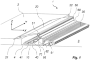
- Fig. 1 illustrates a door threshold 1 according to an embodiment of the invention.
- the door threshold 1 is arranged at a doorway between a first floor surface 2 and a second floor surface 3.
- the doorway may be between inside and outside of a building, wherein the first floor surface 2 may be at the inside of the building and the second floor surface 3 may be at the outside of the building.
- the first floor surface 2 is at a higher level in a vertical direction than the second floor surface 3.
- the door threshold 1 has a longitudinal extension in a direction Y corresponding to the width direction of the doorway.
- the door threshold 1 further extends along the floor surfaces 2, 3 in a throughgoing direction X (may also be referred to a horizontal direction), corresponding to the direction along which the doorway is passed.
- a vertical or height direction Z may further be defined as a direction perpendicular to any of the floor surfaces 2, 3.
- the door threshold 1 comprises a first ramp member 20 extending, at a first end 21, from the first floor surface 2 towards a door 5 of the doorway (see fig. 2a ). In a resting position, as illustrated in figs. 1 , 2a and 3a , the first ramp member 20 extends from the first floor surface 2 sloping upwards towards the door 5, along the throughgoing direction X.
- the door threshold 1 further comprises a second ramp member 30 extending sloping downwards towards the second floor surface 3.
- the first and/or second floor surfaces 2, 3 may alternatively be ground surfaces.
- the second ramp member 30 may either extend all the way to be in contact with the second floor surface 3, or comprise, as illustrated in figs. 2-3 , a door sill 31.
- the door sill 31 is attached to the second ramp member 30 and extends to provide a ramp all the way to the second floor surface 3.
- the door threshold 1 further comprises a bottom member 10.
- the bottom member 10 is configured to be arranged on a bottom surface 4 of the doorway.
- the bottom surface 4 is a horizontal surface between the first and second floor surfaces 2, 3, and at least partly below the door 5 when the door is closed.
- the bottom surface 4 may be a part of the second floor surface 3, and/or parallel to the floor surfaces 2, 3.
- the second ramp member 30 is attached to the bottom member 10. In the illustrated embodiment, the second ramp member 30 is integrally formed with the bottom member 10.
- the door threshold 1 further comprises a spring member 40 and a link member 50.
- the link member 50 has a first end 51 at which it is rotatably attached to a second end 22 of the first ramp member 20.
- the second end 22 of the first ramp member 20 is an end opposite to the first end 21 along the throughgoing direction X.
- the spring member 40 is attached at a first end 41 to the bottom member 10 at a first end 11 of the bottom member 10.
- the first end 11 of the bottom member 10 is an end in the throughgoing direction X remote from the second ramp member 30.
- the spring member 40 is at a second end 42 attached to a second end 52 of the link member 50.
- the first end 51 of the link member 50 is rotatably attached to the second end 22 of the first ramp member 20.
- the connection between the first ramp member 20 and the link member 50 is formed in a hinge like manner along the longitudinal direction Y of the two members 20, 50.
- the spring member 40 provides a biasing force on the link member 50 such that the first ramp member 20 in a resting state extends in the sloping upwards direction.
- the link member 50 extends towards the bottom member 10 and/or the bottom surface 4 along the height direction Z.
- the sloping upwards first ramp member 20 together with the downward extending link member 50 thereby provides, in the resting state, a sealing that fulfills the requirements in terms of climate and safety.
- a sealing member 60 is arranged between the second end 52 of the link member 50 and the second ramp member 30.
- the sealing member 60 is made of a flexible material, such as rubber or soft plastics material.
- the first ramp member 20 When a force is applied to the first ramp member 20, such as when the door threshold 1 is stepped on or when pushed down by a wheelchair, the first ramp member 20 is moved to a down pressed position as seen in figs. 2b and 2c . In the down pressed position the first ramp member 20 is, in the illustrated embodiment, in a substantially horizontal position. The second end 22 of the first ramp member 20 is then at substantially the same height in the vertical direction Z as a second end 32 of the second ramp member 30. This provides a smooth path through the doorway and over the door threshold 1.
- Fig. 2b illustrates the embodiment wherein the first end 21 of the first ramp member 20 is fixed in the horizontal direction X relative to the first floor surface 2.
- the second end 22 of the first ramp member 20 is moved in the vertical direction Z to the down pressed position as illustrated in fig. 2b .
- the spring member 40 is compressed.
- the gap 7 between the second end 22 of the first ramp member 20 and the second end of the second ramp member 30 is substantially the same in the horizontal direction as in the resting position.
- Fig. 2c illustrates the embodiment wherein the first ramp member 20, when the first ramp member 20 is pushed to the down pressed position, also moves in the horizontal direction X.
- the link member 50 rotates in the rotational direction A1. The rotation takes place such that the second end 52 of the link member 50 rotates towards a bottom side 23 of the first ramp member 20.
- the bottom side 23 is the side opposite a door facing side, or user visible side, of the first ramp member 20.
- the spring 40 is compressed.
- the spring 40 is configured such that it provides the rotation of the link member 50 in the direction A1.
- the spring 40 is a blade spring.
- the gap 7 between the second end 22 of the first ramp member 20 and the second end 32 of the second ramp member 30 is, when the first ramp member 20 is in the down pressed position, reduced.
- the first ramp member 20 is pushed towards the down pressed position, the second end 22 of the first ramp member 20 moves downward in the vertical direction Z, towards the bottom member 10, and the whole first ramp member 20 moves along the throughgoing direction X towards the second ramp member 30.
- a reduction of the gap 7, provided by the first ramp member 20 moving along the throughgoing direction X provides a smooth transition between the first ramp member 20 and the second ramp member 30. A passing by for instance a wheelchair through the doorway is thereby facilitated.
- the movement of the first ramp member 20 towards the down pressed position may further be described as a rotation of the first ramp member 20 around the first end 21 of the first ramp member 20 at the same time as the first end 21, i.e. the point of rotation, moves along the first floor or ground surface 2 in the throughgoing direction X.
- the sealing member 60 is, when the first ramp member 20 is in the down pressed position bent to keep sealing the gap 7 and follow the movement of the link member 50.
- the gap 7 is thereby kept sealed irrespective if the first ramp member 20 moves in the throughgoing direction X or not.
- the spring member 40 forces the first ramp member 20, via the link member 50, back to the resting position as seen in fig. 2a .
- the first ramp member 20 thereby also moves back to the original position along the throughgoing direction X in the embodiment wherein the first ramp member 20 is horizontally moveable relative to the first floor surface 2.
- the sealing member 60 follows the movement of the link member 50 to seal the increased gap 7.
- Figs. 3a and 3b illustrate an embodiment wherein the door threshold 1 further comprises a link arm 70.
- the link arm 70 is rotatably connected at a first end 71 to the first end 11 of the bottom member 10.
- the link arm 70 is in a second end 72 connected to the link member 50.
- the link arm 70 having a fixed length, further controls the rotational movement along direction A1 of the link member 50.
- the link arm 70 is connected, at the second end 72, to the link member 50 at two positions. Both at the second end 52 of the link member 50 and a center location of the link member 50, between the first and second ends 51, 52 of the link member 50. This further controls the rotational behavior of the link member 50 when the first ramp member 20 is pushed downward in the vertical direction Z.
- the link arm 70 is rotatably connected to the link member 50 at the one or two connection points.
- the bottom member 10 is fixed to the bottom surface 4 of the doorway.
- the connections of the spring member 40 and/or the link arm 70 between the bottom member 10 and the link member 50 causes the first ramp member 20 to move along the throughgoing direction X, towards the second ramp member 30, when being moved towards the down pressed position.
- Fig. 4 illustrates an embodiment in which the door threshold 1 comprises a plurality of spring members 40 and a plurality of link arms 70.
- the spring members 40 and link arms 70 are evenly distributed along the longitudinal direction Y of the door threshold 1.
Landscapes
- Engineering & Computer Science (AREA)
- Civil Engineering (AREA)
- Structural Engineering (AREA)
- Specific Sealing Or Ventilating Devices For Doors And Windows (AREA)
Claims (15)
- Türschwelle (1) zur Anordnung unter einer Tür (5) an einer Türöffnung, wobei sich die Türöffnung zwischen einem ersten Boden oder einer ersten Bodenfläche (2) und einem zweiten Boden oder einer zweiten Bodenfläche (3) befindet, wobei der erste Boden oder die erste Bodenfläche (2) einen Höhenunterschied zu dem zweiten Boden oder der zweiten Bodenfläche (3) aufweist, wobei die Türschwelle (1) umfasst:ein unteres Element (10), das eingerichtet ist, um im Gebrauch auf einer horizontalen unteren Fläche (4) der Türöffnung angeordnet zu sein;ein erstes Rampenelement (20), das eingerichtet ist, um im Gebrauch an einem ersten Ende (21) des ersten Rampenelements mit dem ersten Boden oder der ersten Bodenfläche (2) in Kontakt zu sein;ein zweites Rampenelement (30), das eingerichtet ist, sich im Gebrauch in Richtung des zweiten Bodens oder der zweiten Bodenfläche (3) zu erstrecken;ein Federelement (40), das in einem ersten Ende (41) an dem unteren Element (10) angebracht ist;ein Verbindungselement (50), das in einem ersten Ende (51) drehbar an dem ersten Rampenelement (20) angebracht ist und in einem zweiten Ende (52) mit einem zweiten Ende (42) des Federelements (40) verbunden ist;wobei das Federelement (40) über das Verbindungselement (50) eine Vorspannkraft auf das erste Rampenelement (20) in Richtung einer Ruheposition aufbringt; undwobei, wenn eine Kraft auf das erste Rampenelement (20) ausgeübt wird, sich das erste Rampenelement durch Drehung um das erste Ende (21) des ersten Rampenelements (20) in Richtung einer nach unten gedrückten Position bewegt.
- Türschwelle (1) nach Anspruch 1, wobei das Federelement (40) und das Verbindungselement (50) derart eingerichtet sind, dass, wenn eine Kraft auf das erste Rampenelement (20) derart ausgeübt wird, dass sich das erste Rampenelement in Richtung der nach unten gedrückten Position bewegt, sich das erste Rampenelement ferner in Richtung des zweiten Rampenelements in einer horizontalen Richtung (X) bewegt.
- Türschwelle (1) nach Anspruch 1 oder 2, wobei, wenn das erste Rampenelement (20) aus der Ruheposition in Richtung der nach unten gedrückten Position bewegt wird, ein horizontaler Abstand zwischen dem ersten Rampenelement (20) und dem zweiten Rampenelement (30) verringert wird.
- Türschwelle (1) nach einem der vorhergehenden Ansprüche, ferner umfassend ein flexibles Dichtungselement (60), das angeordnet ist, um einen Spalt (7) zwischen dem Verbindungselement (50) und dem zweiten Rampenelement (30) abzudecken.
- Türschwelle (1) nach Anspruch 4, wobei das Dichtungselement (60) in einem ersten Ende (61) an dem zweiten Rampenelement (30) angeordnet ist und in einem zweiten Ende (62) an dem zweiten Ende (52) des Verbindungselements (50) angeordnet ist.
- Türschwelle (1) nach Anspruch 4 oder 5, wobei das zweite Rampenelement (30) an einem zweiten Ende (32) an dem unteren Element (10) angebracht ist und das Dichtungselement (50) an dem unteren Element (10) an der Stelle angebracht ist, an der das zweite Rampenelement (30) an dem unteren Element (10) angebracht ist.
- Türschwelle (1) nach einem der vorhergehenden Ansprüche, wobei, wenn sich das erste Rampenelement (20) in der nach unten gedrückten Position befindet, das zweite Ende (22) des ersten Rampenelements (20) und ein zweites Ende (32) des zweiten Rampenelements (30) in einer vertikalen Richtung (Z) im Wesentlichen auf der gleichen Höhe liegen.
- Türschwelle (1) nach einem der vorhergehenden Ansprüche, wobei sich das Verbindungselement (50), wenn sich das erste Rampenelement (20) in der Ruheposition befindet, in eine im Wesentlichen vertikale Richtung (Z) erstreckt.
- Türschwelle (1) nach einem der Ansprüche 2-3, wobei das erste Rampenelement (20) eingerichtet ist, um, wenn es in Richtung der nach unten gedrückten Position bewegt wird, sich um das erste Ende (21) des ersten Rampenelements (20) zu drehen, so dass sich das erste Ende (21) entlang des ersten Bodens oder der ersten Bodenfläche (2) in einer horizontalen Richtung (X) bewegt.
- Türschwelle (1) nach einem der Ansprüche 2-3, 9, wobei das Verbindungselement (50) eingerichtet ist, um, wenn das erste Rampenelement (20) in Richtung der nach unten gedrückten Position bewegt wird, in einer Richtung (A1) zu einer unteren Seite (23) des ersten Rampenelements (20) zu drehen.
- Türschwelle (1) nach einem der vorhergehenden Ansprüche, wobei das Federelement (40) eine Tellerfeder ist.
- Türschwelle nach einem der vorhergehenden Ansprüche, wobei das untere Element (10) einen horizontalen Abschnitt aufweist, der sich zwischen einem ersten Ende (11) und einem zweiten Ende erstreckt, wobei das zweite Rampenelement (30) an dem zweiten Ende des horizontalen Abschnitts angebracht ist und das Federelement (40) an dem ersten Ende (11) des horizontalen Abschnitts angebracht ist.
- Türschwelle (1) nach einem der vorhergehenden Ansprüche, wobei der zweite Boden oder die zweite Bodenfläche (3) in einer vertikalen Richtung (Z) eine geringere Höhe aufweist als der erste Boden oder die erste Bodenfläche (2).
- Türschwelle nach einem der vorhergehenden Ansprüche, ferner umfassend einen Verbindungsarm (70), der zwischen dem unteren Element (10) und dem Verbindungselement (50) angeordnet ist.
- Türschwelle (1) nach Anspruch 14, wobei der Verbindungsarm (70) in einem ersten Ende (71) drehbar an dem ersten Ende (11) des unteren Elements (10) angebracht ist und in einem zweiten Ende (72) drehbar an dem Verbindungselement (50) angebracht ist.
Priority Applications (1)
| Application Number | Priority Date | Filing Date | Title |
|---|---|---|---|
| EP21195645.3A EP4148223B1 (de) | 2021-09-09 | 2021-09-09 | Federbelastete türschwelle |
Applications Claiming Priority (1)
| Application Number | Priority Date | Filing Date | Title |
|---|---|---|---|
| EP21195645.3A EP4148223B1 (de) | 2021-09-09 | 2021-09-09 | Federbelastete türschwelle |
Publications (3)
| Publication Number | Publication Date |
|---|---|
| EP4148223A1 EP4148223A1 (de) | 2023-03-15 |
| EP4148223B1 true EP4148223B1 (de) | 2024-06-05 |
| EP4148223C0 EP4148223C0 (de) | 2024-06-05 |
Family
ID=77710459
Family Applications (1)
| Application Number | Title | Priority Date | Filing Date |
|---|---|---|---|
| EP21195645.3A Active EP4148223B1 (de) | 2021-09-09 | 2021-09-09 | Federbelastete türschwelle |
Country Status (1)
| Country | Link |
|---|---|
| EP (1) | EP4148223B1 (de) |
Families Citing this family (2)
| Publication number | Priority date | Publication date | Assignee | Title |
|---|---|---|---|---|
| DK181582B1 (en) * | 2023-03-31 | 2024-06-07 | Excellent Holding Aps | Bridge structure and method of providing a smooth transition way across a threshold by means of the bridge structure |
| EP4471246A1 (de) * | 2023-05-29 | 2024-12-04 | Meglio of Sweden AB | Türschwelle |
Family Cites Families (3)
| Publication number | Priority date | Publication date | Assignee | Title |
|---|---|---|---|---|
| US8813427B2 (en) * | 2012-05-17 | 2014-08-26 | Quanex Corporation | Threshold assembly having a rail and a drainage element |
| US9528314B2 (en) * | 2015-05-20 | 2016-12-27 | Endura Products, Inc. | Entryway with articulating threshold |
| US11085229B2 (en) * | 2018-07-23 | 2021-08-10 | Endura Products, Llc | Threshold and threshold cap assembly |
-
2021
- 2021-09-09 EP EP21195645.3A patent/EP4148223B1/de active Active
Also Published As
| Publication number | Publication date |
|---|---|
| EP4148223C0 (de) | 2024-06-05 |
| EP4148223A1 (de) | 2023-03-15 |
Similar Documents
| Publication | Publication Date | Title |
|---|---|---|
| EP4148223A1 (de) | Federbelastete türschwelle | |
| US6973753B2 (en) | Sliding door system | |
| US7320496B2 (en) | Sealing arrangement for a transit vehicle | |
| CA2928089C (en) | Entryway with articulating threshold | |
| US8615930B2 (en) | Lifting device adapted to be mounted in an openable structure | |
| RU2714630C2 (ru) | Дверная или оконная петля | |
| EP3147445B1 (de) | Tür oder fenster | |
| US9453368B2 (en) | Door seal assembly | |
| CA2285835C (en) | Hinge mechanism | |
| US6766562B1 (en) | Extendible hinge | |
| US7350636B2 (en) | Door assembly for a chute system | |
| JP2024096510A (ja) | 戸板密着機構及びそれを含む戸 | |
| EP4471246A1 (de) | Türschwelle | |
| KR101778077B1 (ko) | 출입문용 방범 도어 | |
| US5271124A (en) | Hinge suitable for use in a roof window assembly | |
| KR101028141B1 (ko) | 공동주택용 복도 창문의 자동개폐장치 | |
| US20240035321A1 (en) | Window opening control device | |
| JP3486272B2 (ja) | 扉下部の隙間遮蔽装置 | |
| KR101705342B1 (ko) | 건축물용 소방용 방화문 | |
| KR20220162576A (ko) | 방충망이 창틀로부터 이탈하는 것을 방지하는 틀 구조 | |
| KR102146102B1 (ko) | 다용도 자동 창문 개폐 장치 | |
| EP1650393A1 (de) | Schutzelement für eine Tür | |
| US10329818B2 (en) | Hinge assembly | |
| KR102963648B1 (ko) | 방화문용 화재 감지 오토 클로저 시스템 | |
| KR200254820Y1 (ko) | 도어의 하부공간 차단장치 |
Legal Events
| Date | Code | Title | Description |
|---|---|---|---|
| PUAI | Public reference made under article 153(3) epc to a published international application that has entered the european phase |
Free format text: ORIGINAL CODE: 0009012 |
|
| STAA | Information on the status of an ep patent application or granted ep patent |
Free format text: STATUS: THE APPLICATION HAS BEEN PUBLISHED |
|
| AK | Designated contracting states |
Kind code of ref document: A1 Designated state(s): AL AT BE BG CH CY CZ DE DK EE ES FI FR GB GR HR HU IE IS IT LI LT LU LV MC MK MT NL NO PL PT RO RS SE SI SK SM TR |
|
| STAA | Information on the status of an ep patent application or granted ep patent |
Free format text: STATUS: REQUEST FOR EXAMINATION WAS MADE |
|
| 17P | Request for examination filed |
Effective date: 20230907 |
|
| RBV | Designated contracting states (corrected) |
Designated state(s): AL AT BE BG CH CY CZ DE DK EE ES FI FR GB GR HR HU IE IS IT LI LT LU LV MC MK MT NL NO PL PT RO RS SE SI SK SM TR |
|
| GRAP | Despatch of communication of intention to grant a patent |
Free format text: ORIGINAL CODE: EPIDOSNIGR1 |
|
| STAA | Information on the status of an ep patent application or granted ep patent |
Free format text: STATUS: GRANT OF PATENT IS INTENDED |
|
| RIC1 | Information provided on ipc code assigned before grant |
Ipc: E06B 1/70 20060101AFI20240117BHEP |
|
| INTG | Intention to grant announced |
Effective date: 20240212 |
|
| GRAS | Grant fee paid |
Free format text: ORIGINAL CODE: EPIDOSNIGR3 |
|
| GRAA | (expected) grant |
Free format text: ORIGINAL CODE: 0009210 |
|
| STAA | Information on the status of an ep patent application or granted ep patent |
Free format text: STATUS: THE PATENT HAS BEEN GRANTED |
|
| AK | Designated contracting states |
Kind code of ref document: B1 Designated state(s): AL AT BE BG CH CY CZ DE DK EE ES FI FR GB GR HR HU IE IS IT LI LT LU LV MC MK MT NL NO PL PT RO RS SE SI SK SM TR |
|
| REG | Reference to a national code |
Ref country code: CH Ref legal event code: EP |
|
| REG | Reference to a national code |
Ref country code: DE Ref legal event code: R096 Ref document number: 602021014022 Country of ref document: DE |
|
| REG | Reference to a national code |
Ref country code: IE Ref legal event code: FG4D |
|
| U01 | Request for unitary effect filed |
Effective date: 20240627 |
|
| U07 | Unitary effect registered |
Designated state(s): AT BE BG DE DK EE FI FR IT LT LU LV MT NL PT SE SI Effective date: 20240705 |
|
| U20 | Renewal fee for the european patent with unitary effect paid |
Year of fee payment: 4 Effective date: 20240731 |
|
| PG25 | Lapsed in a contracting state [announced via postgrant information from national office to epo] |
Ref country code: HR Free format text: LAPSE BECAUSE OF FAILURE TO SUBMIT A TRANSLATION OF THE DESCRIPTION OR TO PAY THE FEE WITHIN THE PRESCRIBED TIME-LIMIT Effective date: 20240605 |
|
| PG25 | Lapsed in a contracting state [announced via postgrant information from national office to epo] |
Ref country code: GR Free format text: LAPSE BECAUSE OF FAILURE TO SUBMIT A TRANSLATION OF THE DESCRIPTION OR TO PAY THE FEE WITHIN THE PRESCRIBED TIME-LIMIT Effective date: 20240906 |
|
| PG25 | Lapsed in a contracting state [announced via postgrant information from national office to epo] |
Ref country code: ES Free format text: LAPSE BECAUSE OF FAILURE TO SUBMIT A TRANSLATION OF THE DESCRIPTION OR TO PAY THE FEE WITHIN THE PRESCRIBED TIME-LIMIT Effective date: 20240605 |
|
| PG25 | Lapsed in a contracting state [announced via postgrant information from national office to epo] |
Ref country code: NO Free format text: LAPSE BECAUSE OF FAILURE TO SUBMIT A TRANSLATION OF THE DESCRIPTION OR TO PAY THE FEE WITHIN THE PRESCRIBED TIME-LIMIT Effective date: 20240905 Ref country code: HR Free format text: LAPSE BECAUSE OF FAILURE TO SUBMIT A TRANSLATION OF THE DESCRIPTION OR TO PAY THE FEE WITHIN THE PRESCRIBED TIME-LIMIT Effective date: 20240605 Ref country code: GR Free format text: LAPSE BECAUSE OF FAILURE TO SUBMIT A TRANSLATION OF THE DESCRIPTION OR TO PAY THE FEE WITHIN THE PRESCRIBED TIME-LIMIT Effective date: 20240906 Ref country code: ES Free format text: LAPSE BECAUSE OF FAILURE TO SUBMIT A TRANSLATION OF THE DESCRIPTION OR TO PAY THE FEE WITHIN THE PRESCRIBED TIME-LIMIT Effective date: 20240605 Ref country code: RS Free format text: LAPSE BECAUSE OF FAILURE TO SUBMIT A TRANSLATION OF THE DESCRIPTION OR TO PAY THE FEE WITHIN THE PRESCRIBED TIME-LIMIT Effective date: 20240905 |
|
| PG25 | Lapsed in a contracting state [announced via postgrant information from national office to epo] |
Ref country code: PL Free format text: LAPSE BECAUSE OF FAILURE TO SUBMIT A TRANSLATION OF THE DESCRIPTION OR TO PAY THE FEE WITHIN THE PRESCRIBED TIME-LIMIT Effective date: 20240605 |
|
| PG25 | Lapsed in a contracting state [announced via postgrant information from national office to epo] |
Ref country code: IS Free format text: LAPSE BECAUSE OF FAILURE TO SUBMIT A TRANSLATION OF THE DESCRIPTION OR TO PAY THE FEE WITHIN THE PRESCRIBED TIME-LIMIT Effective date: 20241005 |
|
| PG25 | Lapsed in a contracting state [announced via postgrant information from national office to epo] |
Ref country code: CZ Free format text: LAPSE BECAUSE OF FAILURE TO SUBMIT A TRANSLATION OF THE DESCRIPTION OR TO PAY THE FEE WITHIN THE PRESCRIBED TIME-LIMIT Effective date: 20240605 |
|
| PG25 | Lapsed in a contracting state [announced via postgrant information from national office to epo] |
Ref country code: RO Free format text: LAPSE BECAUSE OF FAILURE TO SUBMIT A TRANSLATION OF THE DESCRIPTION OR TO PAY THE FEE WITHIN THE PRESCRIBED TIME-LIMIT Effective date: 20240605 Ref country code: SK Free format text: LAPSE BECAUSE OF FAILURE TO SUBMIT A TRANSLATION OF THE DESCRIPTION OR TO PAY THE FEE WITHIN THE PRESCRIBED TIME-LIMIT Effective date: 20240605 |
|
| PG25 | Lapsed in a contracting state [announced via postgrant information from national office to epo] |
Ref country code: SM Free format text: LAPSE BECAUSE OF FAILURE TO SUBMIT A TRANSLATION OF THE DESCRIPTION OR TO PAY THE FEE WITHIN THE PRESCRIBED TIME-LIMIT Effective date: 20240605 |
|
| PG25 | Lapsed in a contracting state [announced via postgrant information from national office to epo] |
Ref country code: SM Free format text: LAPSE BECAUSE OF FAILURE TO SUBMIT A TRANSLATION OF THE DESCRIPTION OR TO PAY THE FEE WITHIN THE PRESCRIBED TIME-LIMIT Effective date: 20240605 Ref country code: SK Free format text: LAPSE BECAUSE OF FAILURE TO SUBMIT A TRANSLATION OF THE DESCRIPTION OR TO PAY THE FEE WITHIN THE PRESCRIBED TIME-LIMIT Effective date: 20240605 Ref country code: RO Free format text: LAPSE BECAUSE OF FAILURE TO SUBMIT A TRANSLATION OF THE DESCRIPTION OR TO PAY THE FEE WITHIN THE PRESCRIBED TIME-LIMIT Effective date: 20240605 Ref country code: PL Free format text: LAPSE BECAUSE OF FAILURE TO SUBMIT A TRANSLATION OF THE DESCRIPTION OR TO PAY THE FEE WITHIN THE PRESCRIBED TIME-LIMIT Effective date: 20240605 Ref country code: IS Free format text: LAPSE BECAUSE OF FAILURE TO SUBMIT A TRANSLATION OF THE DESCRIPTION OR TO PAY THE FEE WITHIN THE PRESCRIBED TIME-LIMIT Effective date: 20241005 Ref country code: CZ Free format text: LAPSE BECAUSE OF FAILURE TO SUBMIT A TRANSLATION OF THE DESCRIPTION OR TO PAY THE FEE WITHIN THE PRESCRIBED TIME-LIMIT Effective date: 20240605 |
|
| PLBE | No opposition filed within time limit |
Free format text: ORIGINAL CODE: 0009261 |
|
| STAA | Information on the status of an ep patent application or granted ep patent |
Free format text: STATUS: NO OPPOSITION FILED WITHIN TIME LIMIT |
|
| PG25 | Lapsed in a contracting state [announced via postgrant information from national office to epo] |
Ref country code: MC Free format text: LAPSE BECAUSE OF FAILURE TO SUBMIT A TRANSLATION OF THE DESCRIPTION OR TO PAY THE FEE WITHIN THE PRESCRIBED TIME-LIMIT Effective date: 20240605 |
|
| REG | Reference to a national code |
Ref country code: CH Ref legal event code: PL |
|
| 26N | No opposition filed |
Effective date: 20250306 |
|
| PG25 | Lapsed in a contracting state [announced via postgrant information from national office to epo] |
Ref country code: CH Free format text: LAPSE BECAUSE OF NON-PAYMENT OF DUE FEES Effective date: 20240930 |
|
| PG25 | Lapsed in a contracting state [announced via postgrant information from national office to epo] |
Ref country code: IE Free format text: LAPSE BECAUSE OF NON-PAYMENT OF DUE FEES Effective date: 20240909 |
|
| U20 | Renewal fee for the european patent with unitary effect paid |
Year of fee payment: 5 Effective date: 20250815 |
|
| PG25 | Lapsed in a contracting state [announced via postgrant information from national office to epo] |
Ref country code: CY Free format text: LAPSE BECAUSE OF FAILURE TO SUBMIT A TRANSLATION OF THE DESCRIPTION OR TO PAY THE FEE WITHIN THE PRESCRIBED TIME-LIMIT; INVALID AB INITIO Effective date: 20210909 |
|
| PG25 | Lapsed in a contracting state [announced via postgrant information from national office to epo] |
Ref country code: HU Free format text: LAPSE BECAUSE OF FAILURE TO SUBMIT A TRANSLATION OF THE DESCRIPTION OR TO PAY THE FEE WITHIN THE PRESCRIBED TIME-LIMIT; INVALID AB INITIO Effective date: 20210909 |