EP4148191A1 - Rotary construction machine - Google Patents
Rotary construction machine Download PDFInfo
- Publication number
- EP4148191A1 EP4148191A1 EP21821312.2A EP21821312A EP4148191A1 EP 4148191 A1 EP4148191 A1 EP 4148191A1 EP 21821312 A EP21821312 A EP 21821312A EP 4148191 A1 EP4148191 A1 EP 4148191A1
- Authority
- EP
- European Patent Office
- Prior art keywords
- slewing
- boom
- leading end
- pump
- capacity
- Prior art date
- Legal status (The legal status is an assumption and is not a legal conclusion. Google has not performed a legal analysis and makes no representation as to the accuracy of the status listed.)
- Pending
Links
Images



Classifications
-
- E—FIXED CONSTRUCTIONS
- E02—HYDRAULIC ENGINEERING; FOUNDATIONS; SOIL SHIFTING
- E02F—DREDGING; SOIL-SHIFTING
- E02F3/00—Dredgers; Soil-shifting machines
- E02F3/04—Dredgers; Soil-shifting machines mechanically-driven
- E02F3/28—Dredgers; Soil-shifting machines mechanically-driven with digging tools mounted on a dipper- or bucket-arm, i.e. there is either one arm or a pair of arms, e.g. dippers, buckets
- E02F3/36—Component parts
- E02F3/42—Drives for dippers, buckets, dipper-arms or bucket-arms
- E02F3/43—Control of dipper or bucket position; Control of sequence of drive operations
- E02F3/435—Control of dipper or bucket position; Control of sequence of drive operations for dipper-arms, backhoes or the like
-
- E—FIXED CONSTRUCTIONS
- E02—HYDRAULIC ENGINEERING; FOUNDATIONS; SOIL SHIFTING
- E02F—DREDGING; SOIL-SHIFTING
- E02F3/00—Dredgers; Soil-shifting machines
- E02F3/04—Dredgers; Soil-shifting machines mechanically-driven
- E02F3/96—Dredgers; Soil-shifting machines mechanically-driven with arrangements for alternate or simultaneous use of different digging elements
- E02F3/965—Dredgers; Soil-shifting machines mechanically-driven with arrangements for alternate or simultaneous use of different digging elements of metal-cutting or concrete-crushing implements
-
- E—FIXED CONSTRUCTIONS
- E02—HYDRAULIC ENGINEERING; FOUNDATIONS; SOIL SHIFTING
- E02F—DREDGING; SOIL-SHIFTING
- E02F3/00—Dredgers; Soil-shifting machines
- E02F3/04—Dredgers; Soil-shifting machines mechanically-driven
- E02F3/28—Dredgers; Soil-shifting machines mechanically-driven with digging tools mounted on a dipper- or bucket-arm, i.e. there is either one arm or a pair of arms, e.g. dippers, buckets
- E02F3/36—Component parts
- E02F3/40—Dippers; Buckets ; Grab devices, e.g. manufacturing processes for buckets, form, geometry or material of buckets
- E02F3/413—Dippers; Buckets ; Grab devices, e.g. manufacturing processes for buckets, form, geometry or material of buckets with grabbing device
- E02F3/4135—Dippers; Buckets ; Grab devices, e.g. manufacturing processes for buckets, form, geometry or material of buckets with grabbing device with grabs mounted directly on a boom
-
- E—FIXED CONSTRUCTIONS
- E02—HYDRAULIC ENGINEERING; FOUNDATIONS; SOIL SHIFTING
- E02F—DREDGING; SOIL-SHIFTING
- E02F3/00—Dredgers; Soil-shifting machines
- E02F3/04—Dredgers; Soil-shifting machines mechanically-driven
- E02F3/28—Dredgers; Soil-shifting machines mechanically-driven with digging tools mounted on a dipper- or bucket-arm, i.e. there is either one arm or a pair of arms, e.g. dippers, buckets
- E02F3/36—Component parts
- E02F3/42—Drives for dippers, buckets, dipper-arms or bucket-arms
- E02F3/425—Drive systems for dipper-arms, backhoes or the like
-
- E—FIXED CONSTRUCTIONS
- E02—HYDRAULIC ENGINEERING; FOUNDATIONS; SOIL SHIFTING
- E02F—DREDGING; SOIL-SHIFTING
- E02F3/00—Dredgers; Soil-shifting machines
- E02F3/04—Dredgers; Soil-shifting machines mechanically-driven
- E02F3/96—Dredgers; Soil-shifting machines mechanically-driven with arrangements for alternate or simultaneous use of different digging elements
- E02F3/966—Dredgers; Soil-shifting machines mechanically-driven with arrangements for alternate or simultaneous use of different digging elements of hammer-type tools
-
- E—FIXED CONSTRUCTIONS
- E02—HYDRAULIC ENGINEERING; FOUNDATIONS; SOIL SHIFTING
- E02F—DREDGING; SOIL-SHIFTING
- E02F9/00—Component parts of dredgers or soil-shifting machines, not restricted to one of the kinds covered by groups E02F3/00 - E02F7/00
- E02F9/08—Superstructures; Supports for superstructures
- E02F9/10—Supports for movable superstructures mounted on travelling or walking gears or on other superstructures
- E02F9/12—Slewing or traversing gears
- E02F9/121—Turntables, i.e. structure rotatable about 360°
- E02F9/123—Drives or control devices specially adapted therefor
-
- E—FIXED CONSTRUCTIONS
- E02—HYDRAULIC ENGINEERING; FOUNDATIONS; SOIL SHIFTING
- E02F—DREDGING; SOIL-SHIFTING
- E02F9/00—Component parts of dredgers or soil-shifting machines, not restricted to one of the kinds covered by groups E02F3/00 - E02F7/00
- E02F9/20—Drives; Control devices
- E02F9/22—Hydraulic or pneumatic drives
- E02F9/2221—Control of flow rate; Load sensing arrangements
- E02F9/2225—Control of flow rate; Load sensing arrangements using pressure-compensating valves
- E02F9/2228—Control of flow rate; Load sensing arrangements using pressure-compensating valves including an electronic controller
-
- E—FIXED CONSTRUCTIONS
- E02—HYDRAULIC ENGINEERING; FOUNDATIONS; SOIL SHIFTING
- E02F—DREDGING; SOIL-SHIFTING
- E02F9/00—Component parts of dredgers or soil-shifting machines, not restricted to one of the kinds covered by groups E02F3/00 - E02F7/00
- E02F9/20—Drives; Control devices
- E02F9/22—Hydraulic or pneumatic drives
- E02F9/2221—Control of flow rate; Load sensing arrangements
- E02F9/2232—Control of flow rate; Load sensing arrangements using one or more variable displacement pumps
- E02F9/2235—Control of flow rate; Load sensing arrangements using one or more variable displacement pumps including an electronic controller
-
- E—FIXED CONSTRUCTIONS
- E02—HYDRAULIC ENGINEERING; FOUNDATIONS; SOIL SHIFTING
- E02F—DREDGING; SOIL-SHIFTING
- E02F9/00—Component parts of dredgers or soil-shifting machines, not restricted to one of the kinds covered by groups E02F3/00 - E02F7/00
- E02F9/20—Drives; Control devices
- E02F9/22—Hydraulic or pneumatic drives
- E02F9/2221—Control of flow rate; Load sensing arrangements
- E02F9/2239—Control of flow rate; Load sensing arrangements using two or more pumps with cross-assistance
- E02F9/2242—Control of flow rate; Load sensing arrangements using two or more pumps with cross-assistance including an electronic controller
-
- E—FIXED CONSTRUCTIONS
- E02—HYDRAULIC ENGINEERING; FOUNDATIONS; SOIL SHIFTING
- E02F—DREDGING; SOIL-SHIFTING
- E02F9/00—Component parts of dredgers or soil-shifting machines, not restricted to one of the kinds covered by groups E02F3/00 - E02F7/00
- E02F9/20—Drives; Control devices
- E02F9/22—Hydraulic or pneumatic drives
- E02F9/2278—Hydraulic circuits
- E02F9/2292—Systems with two or more pumps
-
- E—FIXED CONSTRUCTIONS
- E02—HYDRAULIC ENGINEERING; FOUNDATIONS; SOIL SHIFTING
- E02F—DREDGING; SOIL-SHIFTING
- E02F9/00—Component parts of dredgers or soil-shifting machines, not restricted to one of the kinds covered by groups E02F3/00 - E02F7/00
- E02F9/20—Drives; Control devices
- E02F9/22—Hydraulic or pneumatic drives
- E02F9/2278—Hydraulic circuits
- E02F9/2296—Systems with a variable displacement pump
-
- E—FIXED CONSTRUCTIONS
- E02—HYDRAULIC ENGINEERING; FOUNDATIONS; SOIL SHIFTING
- E02F—DREDGING; SOIL-SHIFTING
- E02F9/00—Component parts of dredgers or soil-shifting machines, not restricted to one of the kinds covered by groups E02F3/00 - E02F7/00
- E02F9/26—Indicating devices
-
- E—FIXED CONSTRUCTIONS
- E02—HYDRAULIC ENGINEERING; FOUNDATIONS; SOIL SHIFTING
- E02F—DREDGING; SOIL-SHIFTING
- E02F3/00—Dredgers; Soil-shifting machines
- E02F3/04—Dredgers; Soil-shifting machines mechanically-driven
- E02F3/96—Dredgers; Soil-shifting machines mechanically-driven with arrangements for alternate or simultaneous use of different digging elements
- E02F3/963—Arrangements on backhoes for alternate use of different tools
-
- E—FIXED CONSTRUCTIONS
- E02—HYDRAULIC ENGINEERING; FOUNDATIONS; SOIL SHIFTING
- E02F—DREDGING; SOIL-SHIFTING
- E02F9/00—Component parts of dredgers or soil-shifting machines, not restricted to one of the kinds covered by groups E02F3/00 - E02F7/00
- E02F9/20—Drives; Control devices
- E02F9/22—Hydraulic or pneumatic drives
- E02F9/2278—Hydraulic circuits
- E02F9/2285—Pilot-operated systems
-
- F—MECHANICAL ENGINEERING; LIGHTING; HEATING; WEAPONS; BLASTING
- F15—FLUID-PRESSURE ACTUATORS; HYDRAULICS OR PNEUMATICS IN GENERAL
- F15B—SYSTEMS ACTING BY MEANS OF FLUIDS IN GENERAL; FLUID-PRESSURE ACTUATORS, e.g. SERVOMOTORS; DETAILS OF FLUID-PRESSURE SYSTEMS, NOT OTHERWISE PROVIDED FOR
- F15B11/00—Servomotor systems without provision for follow-up action; Circuits therefor
- F15B11/16—Servomotor systems without provision for follow-up action; Circuits therefor with two or more servomotors
- F15B11/17—Servomotor systems without provision for follow-up action; Circuits therefor with two or more servomotors using two or more pumps
-
- F—MECHANICAL ENGINEERING; LIGHTING; HEATING; WEAPONS; BLASTING
- F15—FLUID-PRESSURE ACTUATORS; HYDRAULICS OR PNEUMATICS IN GENERAL
- F15B—SYSTEMS ACTING BY MEANS OF FLUIDS IN GENERAL; FLUID-PRESSURE ACTUATORS, e.g. SERVOMOTORS; DETAILS OF FLUID-PRESSURE SYSTEMS, NOT OTHERWISE PROVIDED FOR
- F15B2211/00—Circuits for servomotor systems
- F15B2211/20—Fluid pressure source, e.g. accumulator or variable axial piston pump
- F15B2211/205—Systems with pumps
- F15B2211/2053—Type of pump
- F15B2211/20546—Type of pump variable capacity
-
- F—MECHANICAL ENGINEERING; LIGHTING; HEATING; WEAPONS; BLASTING
- F15—FLUID-PRESSURE ACTUATORS; HYDRAULICS OR PNEUMATICS IN GENERAL
- F15B—SYSTEMS ACTING BY MEANS OF FLUIDS IN GENERAL; FLUID-PRESSURE ACTUATORS, e.g. SERVOMOTORS; DETAILS OF FLUID-PRESSURE SYSTEMS, NOT OTHERWISE PROVIDED FOR
- F15B2211/00—Circuits for servomotor systems
- F15B2211/20—Fluid pressure source, e.g. accumulator or variable axial piston pump
- F15B2211/205—Systems with pumps
- F15B2211/20576—Systems with pumps with multiple pumps
-
- F—MECHANICAL ENGINEERING; LIGHTING; HEATING; WEAPONS; BLASTING
- F15—FLUID-PRESSURE ACTUATORS; HYDRAULICS OR PNEUMATICS IN GENERAL
- F15B—SYSTEMS ACTING BY MEANS OF FLUIDS IN GENERAL; FLUID-PRESSURE ACTUATORS, e.g. SERVOMOTORS; DETAILS OF FLUID-PRESSURE SYSTEMS, NOT OTHERWISE PROVIDED FOR
- F15B2211/00—Circuits for servomotor systems
- F15B2211/30—Directional control
- F15B2211/305—Directional control characterised by the type of valves
- F15B2211/3056—Assemblies of multiple valves
- F15B2211/30565—Assemblies of multiple valves having multiple valves for a single output member, e.g. for creating higher valve function by use of multiple valves like two 2/2-valves replacing a 5/3-valve
-
- F—MECHANICAL ENGINEERING; LIGHTING; HEATING; WEAPONS; BLASTING
- F15—FLUID-PRESSURE ACTUATORS; HYDRAULICS OR PNEUMATICS IN GENERAL
- F15B—SYSTEMS ACTING BY MEANS OF FLUIDS IN GENERAL; FLUID-PRESSURE ACTUATORS, e.g. SERVOMOTORS; DETAILS OF FLUID-PRESSURE SYSTEMS, NOT OTHERWISE PROVIDED FOR
- F15B2211/00—Circuits for servomotor systems
- F15B2211/30—Directional control
- F15B2211/305—Directional control characterised by the type of valves
- F15B2211/3056—Assemblies of multiple valves
- F15B2211/3059—Assemblies of multiple valves having multiple valves for multiple output members
- F15B2211/30595—Assemblies of multiple valves having multiple valves for multiple output members with additional valves between the groups of valves for multiple output members
-
- F—MECHANICAL ENGINEERING; LIGHTING; HEATING; WEAPONS; BLASTING
- F15—FLUID-PRESSURE ACTUATORS; HYDRAULICS OR PNEUMATICS IN GENERAL
- F15B—SYSTEMS ACTING BY MEANS OF FLUIDS IN GENERAL; FLUID-PRESSURE ACTUATORS, e.g. SERVOMOTORS; DETAILS OF FLUID-PRESSURE SYSTEMS, NOT OTHERWISE PROVIDED FOR
- F15B2211/00—Circuits for servomotor systems
- F15B2211/30—Directional control
- F15B2211/32—Directional control characterised by the type of actuation
- F15B2211/327—Directional control characterised by the type of actuation electrically or electronically
-
- F—MECHANICAL ENGINEERING; LIGHTING; HEATING; WEAPONS; BLASTING
- F15—FLUID-PRESSURE ACTUATORS; HYDRAULICS OR PNEUMATICS IN GENERAL
- F15B—SYSTEMS ACTING BY MEANS OF FLUIDS IN GENERAL; FLUID-PRESSURE ACTUATORS, e.g. SERVOMOTORS; DETAILS OF FLUID-PRESSURE SYSTEMS, NOT OTHERWISE PROVIDED FOR
- F15B2211/00—Circuits for servomotor systems
- F15B2211/30—Directional control
- F15B2211/32—Directional control characterised by the type of actuation
- F15B2211/329—Directional control characterised by the type of actuation actuated by fluid pressure
-
- F—MECHANICAL ENGINEERING; LIGHTING; HEATING; WEAPONS; BLASTING
- F15—FLUID-PRESSURE ACTUATORS; HYDRAULICS OR PNEUMATICS IN GENERAL
- F15B—SYSTEMS ACTING BY MEANS OF FLUIDS IN GENERAL; FLUID-PRESSURE ACTUATORS, e.g. SERVOMOTORS; DETAILS OF FLUID-PRESSURE SYSTEMS, NOT OTHERWISE PROVIDED FOR
- F15B2211/00—Circuits for servomotor systems
- F15B2211/30—Directional control
- F15B2211/36—Pilot pressure sensing
-
- F—MECHANICAL ENGINEERING; LIGHTING; HEATING; WEAPONS; BLASTING
- F15—FLUID-PRESSURE ACTUATORS; HYDRAULICS OR PNEUMATICS IN GENERAL
- F15B—SYSTEMS ACTING BY MEANS OF FLUIDS IN GENERAL; FLUID-PRESSURE ACTUATORS, e.g. SERVOMOTORS; DETAILS OF FLUID-PRESSURE SYSTEMS, NOT OTHERWISE PROVIDED FOR
- F15B2211/00—Circuits for servomotor systems
- F15B2211/60—Circuit components or control therefor
- F15B2211/63—Electronic controllers
- F15B2211/6303—Electronic controllers using input signals
- F15B2211/6306—Electronic controllers using input signals representing a pressure
- F15B2211/6309—Electronic controllers using input signals representing a pressure the pressure being a pressure source supply pressure
-
- F—MECHANICAL ENGINEERING; LIGHTING; HEATING; WEAPONS; BLASTING
- F15—FLUID-PRESSURE ACTUATORS; HYDRAULICS OR PNEUMATICS IN GENERAL
- F15B—SYSTEMS ACTING BY MEANS OF FLUIDS IN GENERAL; FLUID-PRESSURE ACTUATORS, e.g. SERVOMOTORS; DETAILS OF FLUID-PRESSURE SYSTEMS, NOT OTHERWISE PROVIDED FOR
- F15B2211/00—Circuits for servomotor systems
- F15B2211/60—Circuit components or control therefor
- F15B2211/63—Electronic controllers
- F15B2211/6303—Electronic controllers using input signals
- F15B2211/6306—Electronic controllers using input signals representing a pressure
- F15B2211/6313—Electronic controllers using input signals representing a pressure the pressure being a load pressure
-
- F—MECHANICAL ENGINEERING; LIGHTING; HEATING; WEAPONS; BLASTING
- F15—FLUID-PRESSURE ACTUATORS; HYDRAULICS OR PNEUMATICS IN GENERAL
- F15B—SYSTEMS ACTING BY MEANS OF FLUIDS IN GENERAL; FLUID-PRESSURE ACTUATORS, e.g. SERVOMOTORS; DETAILS OF FLUID-PRESSURE SYSTEMS, NOT OTHERWISE PROVIDED FOR
- F15B2211/00—Circuits for servomotor systems
- F15B2211/60—Circuit components or control therefor
- F15B2211/63—Electronic controllers
- F15B2211/6303—Electronic controllers using input signals
- F15B2211/6306—Electronic controllers using input signals representing a pressure
- F15B2211/6316—Electronic controllers using input signals representing a pressure the pressure being a pilot pressure
-
- F—MECHANICAL ENGINEERING; LIGHTING; HEATING; WEAPONS; BLASTING
- F15—FLUID-PRESSURE ACTUATORS; HYDRAULICS OR PNEUMATICS IN GENERAL
- F15B—SYSTEMS ACTING BY MEANS OF FLUIDS IN GENERAL; FLUID-PRESSURE ACTUATORS, e.g. SERVOMOTORS; DETAILS OF FLUID-PRESSURE SYSTEMS, NOT OTHERWISE PROVIDED FOR
- F15B2211/00—Circuits for servomotor systems
- F15B2211/60—Circuit components or control therefor
- F15B2211/665—Methods of control using electronic components
- F15B2211/6652—Control of the pressure source, e.g. control of the swash plate angle
-
- F—MECHANICAL ENGINEERING; LIGHTING; HEATING; WEAPONS; BLASTING
- F15—FLUID-PRESSURE ACTUATORS; HYDRAULICS OR PNEUMATICS IN GENERAL
- F15B—SYSTEMS ACTING BY MEANS OF FLUIDS IN GENERAL; FLUID-PRESSURE ACTUATORS, e.g. SERVOMOTORS; DETAILS OF FLUID-PRESSURE SYSTEMS, NOT OTHERWISE PROVIDED FOR
- F15B2211/00—Circuits for servomotor systems
- F15B2211/70—Output members, e.g. hydraulic motors or cylinders or control therefor
- F15B2211/705—Output members, e.g. hydraulic motors or cylinders or control therefor characterised by the type of output members or actuators
- F15B2211/7051—Linear output members
- F15B2211/7053—Double-acting output members
-
- F—MECHANICAL ENGINEERING; LIGHTING; HEATING; WEAPONS; BLASTING
- F15—FLUID-PRESSURE ACTUATORS; HYDRAULICS OR PNEUMATICS IN GENERAL
- F15B—SYSTEMS ACTING BY MEANS OF FLUIDS IN GENERAL; FLUID-PRESSURE ACTUATORS, e.g. SERVOMOTORS; DETAILS OF FLUID-PRESSURE SYSTEMS, NOT OTHERWISE PROVIDED FOR
- F15B2211/00—Circuits for servomotor systems
- F15B2211/70—Output members, e.g. hydraulic motors or cylinders or control therefor
- F15B2211/705—Output members, e.g. hydraulic motors or cylinders or control therefor characterised by the type of output members or actuators
- F15B2211/7058—Rotary output members
-
- F—MECHANICAL ENGINEERING; LIGHTING; HEATING; WEAPONS; BLASTING
- F15—FLUID-PRESSURE ACTUATORS; HYDRAULICS OR PNEUMATICS IN GENERAL
- F15B—SYSTEMS ACTING BY MEANS OF FLUIDS IN GENERAL; FLUID-PRESSURE ACTUATORS, e.g. SERVOMOTORS; DETAILS OF FLUID-PRESSURE SYSTEMS, NOT OTHERWISE PROVIDED FOR
- F15B2211/00—Circuits for servomotor systems
- F15B2211/70—Output members, e.g. hydraulic motors or cylinders or control therefor
- F15B2211/71—Multiple output members, e.g. multiple hydraulic motors or cylinders
- F15B2211/7135—Combinations of output members of different types, e.g. single-acting cylinders with rotary motors
-
- F—MECHANICAL ENGINEERING; LIGHTING; HEATING; WEAPONS; BLASTING
- F15—FLUID-PRESSURE ACTUATORS; HYDRAULICS OR PNEUMATICS IN GENERAL
- F15B—SYSTEMS ACTING BY MEANS OF FLUIDS IN GENERAL; FLUID-PRESSURE ACTUATORS, e.g. SERVOMOTORS; DETAILS OF FLUID-PRESSURE SYSTEMS, NOT OTHERWISE PROVIDED FOR
- F15B2211/00—Circuits for servomotor systems
- F15B2211/70—Output members, e.g. hydraulic motors or cylinders or control therefor
- F15B2211/71—Multiple output members, e.g. multiple hydraulic motors or cylinders
- F15B2211/7142—Multiple output members, e.g. multiple hydraulic motors or cylinders the output members being arranged in multiple groups
Definitions
- the present invention relates to a slewing-type construction machine such as a hydraulic excavator.
- a slewing-type construction machine such as a hydraulic excavator generally includes a lower travelling body, an upper slewing body slewably mounted on the lower travelling body, a working device including a boom tiltably connected to the upper slewing body, a boom cylinder receiving a supply of hydraulic oil discharged from a first hydraulic pump to raise and lower the boom, a slewing motor receiving a supply of the hydraulic fluid discharged from a second hydraulic pump to slew the upper slewing body, and a confluence switch valve (a boom-accelerating control valve) permitting a confluence of a part of the hydraulic fluid discharged from the second pump with the hydraulic fluid supplied from the first hydraulic pump to the boom cylinder to thereby accelerate the boom raising operation.
- a confluence switch valve a boom-accelerating control valve
- the confluence switch valve is switched to permit a confluence of a part of the hydraulic fluid discharged from the second pump with the hydraulic fluid supplied from the first hydraulic pump to the boom cylinder when a slewing and boom raising manipulation action is performed, the slewing and boom raising manipulation action including the slewing manipulation and the boom raising manipulation.
- a flow rate distribution control part controls a regulator so that a first pump has a discharge flow rate higher than a second pump at a start of the combined operation, and controls the regulator so as to reduce a discharge flow difference as a difference between the respective pump discharge pressures detected by first pump pressure detection means and second pump pressure detection means increases after the slewing becomes steady.
- the working device in the slewing-type construction machine as described above includes a leading end attachment that is selected from a plurality of leading end attachments that are a bucket, a grapple, a crusher, a breaker, a fork, and the like.
- the leading end attachments are configured to be replaceable with one another according to the work content.
- the conventional slewing-type construction machine as described above involves a problem that replacement of a leading end attachment of the working device with another leading end attachment having a weight different from that of the former leading end attachment changes the weight of the working device, and consequently leads to an unbalance between the operation of the boom cylinder and the operation of the slewing motor when the slewing and boom raising manipulation action is performed.
- a specific explanation will be made below.
- An object of the present invention is to provide a slewing-type construction machine that can keep the balance between an operation of a slewing motor and an operation of a boom cylinder from changing when a slewing and boom raising manipulation action is performed, irrespective of a change in the weight of a working device caused by a replacement of a leading end attachment.
- a slewing-type construction machine to be provided includes: a base body; an upper slewing body slewably mounted on the base body; a working device including a boom tiltably connected to the upper slewing body, and a leading end attachment that is selected from a plurality of leading end attachments having different weights from one another; a first hydraulic pump having a variable capacity for discharging hydraulic fluid; a second hydraulic pump having a variable capacity for discharging hydraulic fluid; a boom cylinder receiving a supply of the hydraulic fluid discharged from the first hydraulic pump to raise and lower the boom; a boom control device, in response to a boom raising manipulation causing the boom to move in a rising direction, controlling a flow rate of the hydraulic fluid supplied from the first hydraulic pump to the boom cylinder; a slewing motor receiving a supply of the hydraulic fluid discharged from the second hydraulic pump to slew the upper slewing body; a slewing control device, in response to a slewing manipulation causing the upper slewing
- FIG. 1 is a side view showing a hydraulic excavator 100, which is an exemplary slewing-type construction machine according to the embodiment.
- the hydraulic excavator 100 includes a lower travelling body 1 capable of travelling on the ground, an upper slewing body 2 mounted on the lower travelling body 1 slewably about a vertical axis Z, and a working device 3 mounted on the upper slewing body 2.
- a front portion of the upper slewing body 2 in a front-rear direction is provided with a cab serving as an operating room, and is mounted with the working device 3, whereas a rear portion is provided with an engine room and is mounted with a counterweight.
- the working device 3 includes a boom 4, an arm 5, and a leading end attachment that is selected from a plurality of leading end attachments.
- the hydraulic excavator 100 further includes a boom cylinder 7, an arm cylinder 8, and a leading end attachment cylinder 9.
- the boom 4 includes a base end portion supported at a front end of the upper slewing body 2 tiltably, i.e., swingably in an upper and lower direction about a horizontal axis, and a leading end portion on the opposite thereto.
- the arm 5 includes a base end portion connected to the leading end portion of the boom 4 swingably about the horizontal axis, and a leading end portion on the opposite thereto.
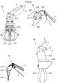
- the leading end attachments include, for example, a bucket 6 shown in FIG. 1 , and a grapple 6A, a crusher 6B, a breaker 6C, and a fork 6D that are shown in FIG. 2 .
- the leading end attachments 6, 6A, 6B, 6C, and 6D are configured to be replaceable with one another, and one of the leading end attachments 6, 6A, 6B, 6C, and 6D is selectively included in the working device 3. Since the leading end attachments 6, 6A, 6B, 6C, and 6D are used for work purposes different from one another, the respective configurations are greatly different, and their respective weights are thus different from one another.
- the bucket 6 shown in FIG. 1 is a leading end attachment adapted for performing, for example, an excavation work in a work site.
- the bucket 6 is swingably attached to the leading end portion of the arm 5.
- the grapple 6A shown in FIG. 2 is a leading end attachment adapted for gripping and transporting scrap in a scrapyard and the like, for example.
- the grapple 6A has a bracket 61A attached to the leading end portion of the arm 5, a grapple main body 62A supported by the bracket 61A, and a plurality of claws 63A (four claws 63A in FIG. 2 ) supported by the grapple main body 62A.
- the crusher 6B is a leading end attachment adapted for performing a demolishing work of a concrete building and the like, for example.
- the crusher 6B has a bracket 61B attached to the leading end portion of the arm 5, a crusher main body 62B supported by the bracket 61B, and a pair of crushing arms 63B supported by the crusher main body 62B.
- the breaker 6C is a leading end attachment adapted for excavating bedrock, splitting rock, and crushing concrete, and the like, for example.
- the breaker 6C has a bracket 61C attached to the leading end portion of the arm 5, a breaker main body 62C supported by the bracket 61C, and a chisel 63C that is supported by the breaker main body 62C and is reciprocable in the axial directions thereof.
- the fork 6D is a leading end attachment adapted for gripping an object to be transported, for example.
- the fork 6D has a bracket 61D attached to the leading end portion of the arm 5, a fork main body 62D supported by the bracket 61D, and a pair of opening and closing arms 63D supported by the fork main body 62D.
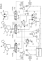
- FIG. 3 is a diagram showing a hydraulic circuit included in the hydraulic excavator 100.
- FIG. 4 is a block diagram showing a configuration of a controller 50 connected to the hydraulic circuit.
- the hydraulic excavator 100 includes a first hydraulic pump 11, a second hydraulic pump 12, a pilot pump 13, a first regulator 11A, a second regulator 12A, a boom control device 20, a slewing motor 10, a slewing control device 30, a confluence switch valve 40, a confluence pilot valve 80, an arm control device, a leading end attachment control device 70, a boom operating pressure detection part 41, a slewing operating pressure detection part 42, a boom raising manipulation detection part 43, a slewing manipulation detection part 44, a leading end attachment manipulation detection part 45, and a controller 50.
- Each of the first hydraulic pump 11 and the second hydraulic pump 12 is a variable capacity hydraulic pump, in which the pump capacity is regulable.
- the first regulator 11A regulates, in response to an input of a capacity instruction signal that is an electric signal from the controller 50, a first pump capacity meaning a pump capacity of the first hydraulic pump 11 to a capacity corresponding to the capacity instruction signal.
- the second regulator 12A regulates, in response to an input of a capacity instruction signal that is an electric signal from the controller 50, a second pump capacity meaning a pump capacity of the second hydraulic pump 12 to a capacity corresponding to the capacity instruction signal.
- the first hydraulic pump 11, the second hydraulic pump 12, and the pilot pump 13 are driven by an unillustrated engine to thereby respectively discharge the hydraulic fluid in a tank.
- the boom cylinder 7 is a hydraulic actuator that operates to raise and lower the boom 4 upon receiving a supply of hydraulic fluid discharged from the first hydraulic pump 11.
- the boom cylinder 7 has a bottom chamber 7a and a rod chamber 7b on the opposite thereto.
- the boom cylinder 7 extends upon a supply of the hydraulic fluid to the bottom chamber 7a to move the boom 4 in the boom raising direction, and concurrently discharge the hydraulic fluid from the rod chamber 7b.
- the boom cylinder 7 retracts upon a supply of the hydraulic fluid to the rod chamber 7b to move the boom 4 in a boom lowering direction, and concurrently discharge the hydraulic fluid from the bottom chamber 7a.
- the boom control device 20 controls, in response to either a boom raising manipulation causing the boom 4 to move in a rising direction or a boom lowering manipulation operation causing the boom 4 to move in a lowering direction, a direction and a flow rate of the hydraulic fluid supplied from the first hydraulic pump 11 to the boom cylinder 7.
- the boom control device 20 includes a boom control valve 21 and a boom manipulating device 22.
- the boom control valve 21 is arranged between the first hydraulic pump 11 and the boom cylinder 7, and is opened and closed in such a manner as to change the direction and the flow rate of the hydraulic fluid supplied from the first hydraulic pump 11 to the boom cylinder 7.
- the boom control valve 21 includes a pilot-operated three-position directional switch valve including a boom raising pilot port 21a and a boom lowering pilot port 21b.
- the boom control valve 21 When no pilot pressure is input to either the boom raising pilot port 21a or the boom lowering pilot port 21b, the boom control valve 21 is kept at a neutral position, and blocks the flow of the hydraulic fluid in a fluid passage between the first hydraulic pump 11 and the boom cylinder 7.
- the fluid passage between the first hydraulic pump 11 and the boom control valve 21 is provided with an unillustrated relief valve.
- the boom control valve 21 shifts from the neutral position to a boom raising position in a stroke commensurate with a magnitude of the boom raising pilot pressure.
- the valve is thus opened in such a manner as to permit the supply of the hydraulic fluid from the first hydraulic pump 11 to the bottom chamber 7a of the boom cylinder 7 at a flow rate corresponding to the stroke, and the discharge of the hydraulic fluid from the rod chamber 7b of the boom cylinder 7. This drives the boom cylinder 7 in the boom raising direction at a speed corresponding to the boom raising pilot pressure.
- the boom control valve 21 shifts from the neutral position to a boom lowering position in a stroke commensurate with a magnitude of the boom lowering pilot pressure.
- the valve is thus opened in such a manner as to permit the supply of the hydraulic fluid from the first hydraulic pump 11 to the rod chamber 7b of the boom cylinder 7 at a flow rate corresponding to the stroke, and the discharge of the hydraulic fluid from the bottom chamber 7a of the boom cylinder 7. This drives the boom cylinder 7 in the boom lowering direction at a speed corresponding to the boom lowering pilot pressure.
- the boom manipulating device 22 operates, in response to either the boom raising manipulation causing the boom 4 to move in the rising direction or the boom lowering manipulation causing the boom 4 to move in the lowering direction, in such a manner as to permit the input of the pilot pressure corresponding to the manipulation from the pilot pump 13 to the boom control valve 21.
- the boom manipulating device 22 includes a boom manipulating lever 23 and a boom remote control valve 24.
- the boom manipulating lever 23 is a member rotatable in response to either the boom raising manipulation or the boom lowering manipulation by an operator.
- the boom raising manipulation and the boom lowering manipulation cause the boom manipulating lever 23 to rotate in directions opposite to each other.
- the boom remote control valve 24 is a pilot valve that is arranged between the pilot pump 13 and the pair of pilot ports 21a, 21b.
- FIG. 3 an illustration of a fluid passage connecting the pilot pump 13 and the boom remote control valve 24 is omitted.
- the boom remote control valve 24 When the boom manipulating lever 23 is not operated and is placed at a neutral position, the boom remote control valve 24 is closed to block the flow of the hydraulic fluid in the fluid passage between the pilot pump 13 and the pair of pilot ports 21a, 21b.
- the boom remote control valve 24 is opened in such a manner as to permit the input of a pilot pressure commensurate with the manipulation amount of the one manipulation from the pilot pump 13 to one of the pair of pilot ports 21a and 21b of the boom control valve 21 that corresponds to a direction of the one manipulation.
- the slewing motor 10 is a hydraulic motor that operates to slew the upper slewing body 2 upon receiving a supply of the hydraulic fluid discharged from the second hydraulic pump 12.
- the slewing motor 10 has an unillustrated output shaft that rotates upon receiving the supply of the hydraulic fluid discharged from the second hydraulic pump 12, and the output shaft is connected to the upper slewing body 2 to slew the upper slewing body 2 to both the directions or leftward and rightward.
- the slewing motor 10 has a first port 10a and a second port 10b, receives the supply of the hydraulic fluid at one of the ports to rotate the output shaft in a direction corresponding to the one port, and discharge the hydraulic fluid from the other port.
- the slewing control device 30 controls, in response to a slewing manipulation causing the upper slewing body 2 to slew, the direction and flow rate of the hydraulic fluid supplied from the second hydraulic pump 12 to the slewing motor 10.
- the slewing control device 30 includes a slewing control valve 31 and a slewing manipulating device 32.
- the slewing control valve 31 is arranged between the second hydraulic pump 12 and the slewing motor 10.
- the slewing control valve 31 selectively directs the hydraulic fluid used to drive the slewing motor 10 from the second hydraulic pump 12 to either the first port 10a or the second port 10b of the slewing motor 10, and controls a slewing flow rate meaning a flow rate of the hydraulic fluid supplied to the slewing motor 10.
- the slewing control valve 31 is a three-position pilot switch valve, and has a pair of slewing pilot ports 31a, 31b.
- the slewing control valve 31 When the pilot pressures supplied to the pair of slewing pilot ports 31a, 31b are zero or minute, the slewing control valve 31 is kept at a neutral position, and blocks the flow of the hydraulic fluid in a fluid passage between the second hydraulic pump 12 and the slewing motor 10.
- the fluid passage between the second hydraulic pump 12 and the slewing control valve 31 is provided with an unillustrated relief valve.
- the slewing control valve 31 shifts from the neutral position to a direction corresponding to the slewing pilot port in a stroke commensurate with a magnitude of the pilot pressure. This causes the slewing motor 10 to operate in a direction and at a speed corresponding the stroke.
- the slewing manipulating device 32 operates, in response to a slewing manipulation causing the upper slewing body 2 to slew, in such a manner as to permit that the pilot pressure corresponding to the slewing manipulation is selectively supplied from the pilot pump 13 to either one of the pair of slewing pilot ports 3 1a, 3 1b of the slewing control valve 31.
- the slewing manipulating device 32 includes a slewing manipulating lever 33 and a slewing remote control valve 34.
- the slewing manipulating lever 33 is a member rotatable in response to the slewing manipulation by an operator.
- the slewing remote control valve 34 is a pilot valve arranged between the pilot pump 13 and the pair of slewing pilot ports 31a, 31b.
- FIG. 3 an illustration of a fluid passage connecting the pilot pump 13 and the slewing remote control valve 34 is omitted.
- the slewing remote control valve 34 When the slewing manipulating lever 33 is not operated and is placed at a neutral position, the slewing remote control valve 34 is closed to block the flow of the hydraulic fluid in the fluid passage between the pilot pump 13 and the pair of slewing pilot ports 31a, 31b.
- the slewing remote control valve 34 is opened in such a manner as to permit the input of a pilot pressure commensurate with the slewing manipulation from the pilot pump 13 to one of the pair of slewing pilot ports 31a, 31b of the slewing control valve 31 that corresponds to a direction of the slewing manipulation.
- the confluence switch valve 40 is configured to be switchable between a permission state of permitting a confluence of at least a part of the hydraulic fluid discharged from the second hydraulic pump 12 with the hydraulic fluid supplied from the first hydraulic pump 11 to the bottom chamber 7a of the boom cylinder 7 and a suspension state of suspending the confluence of the hydraulic fluid discharged from the second hydraulic pump 12 with the hydraulic fluid supplied from the first hydraulic pump 11 to the bottom chamber 7a of the boom cylinder 7.
- the confluence switch valve 40 is configured to direct the hydraulic fluid used to accelerate the movement of the boom 4 in the rising direction, in addition to the hydraulic fluid supplied from the first hydraulic pump 11 to the bottom chamber 7a of the boom cylinder 7, from the second hydraulic pump 12 to the bottom chamber 7a of the boom cylinder 7, and to regulate the flow rate of the hydraulic fluid.
- the confluence switch valve 40 is a two-position pilot switch valve, and has one acceleration pilot port 40a.
- the confluence switch valve 40 When the pilot pressure supplied to the acceleration pilot port 40a is zero or minute, the confluence switch valve 40 is kept at a neutral position, and blocks the flow of the hydraulic fluid in a fluid passage between the second hydraulic pump 12 and the boom cylinder 7.
- the confluence switch valve 40 shifts from the neutral position to a boom raising acceleration position in a stroke commensurate with a magnitude of the pilot pressure.
- the confluence pilot valve 80 includes, for example, a solenoid valve (e.g., a proportional pressure reducing valve or an inversely proportional pressure reducing valve) having a solenoid 80a, and is configured to reduce the pressure of the hydraulic fluid discharged from the pilot pump 13 to a pressure corresponding to an instruction signal (electric signal) input to the solenoid 80a, and to input the reduced pressure to the acceleration pilot port 40a of the confluence switch valve 40.
- a solenoid valve e.g., a proportional pressure reducing valve or an inversely proportional pressure reducing valve
- the arm cylinder 8 shown in FIG. 1 is a hydraulic actuator that operates to raise and lower the arm 5 upon receiving a supply of hydraulic fluid discharged from the second hydraulic pump 12.
- the leading end attachment cylinder 9 shown in FIGS. 1 and 3 is hydraulic actuator that operates to swing the leading end attachment upon receiving a supply of hydraulic fluid discharged from the first hydraulic pump 11.
- the arm control device is a device adapted for operating the arm 5.
- FIG. 3 an illustration of the arm control device is omitted.
- the leading end attachment control device 70 is a device adapted for operating a leading end attachment such as the bucket 6.
- the leading end attachment control device 70 controls, in response to a leading end attachment manipulation causing the leading end attachment included in the working device 3 to swing, a direction and a flow rate of hydraulic fluid supplied from the first hydraulic pump 11 to the leading end attachment cylinder 9.
- the leading end attachment control device 70 includes a leading end attachment control valve 71 and a leading end attachment manipulating device 72.
- the leading end attachment control valve 71 is arranged between the first hydraulic pump 11 and the leading end attachment cylinder 9, and is opened and closed in such a manner as to change the direction and the flow rate of the hydraulic fluid supplied from the first hydraulic pump 11 to the leading end attachment cylinder 9.
- the leading end attachment control valve 71 includes three position direction change valve of a pilot operation type including a pair of pilot ports 71a, 71b.
- the leading end attachment control valve 71 When no pilot pressure is input to the pair of pilot ports 71a, 71b, the leading end attachment control valve 71 is kept at a neutral position, and blocks the flow of the hydraulic fluid in a fluid passage between the first hydraulic pump 11 and the leading end attachment cylinder 9.
- the fluid passage between the first hydraulic pump 11 and the leading end attachment control valve 71 is provided with an unillustrated relief valve.
- the leading end attachment control valve 71 shifts from the neutral position in a stroke commensurate with a magnitude of the pilot pressure to be thereby opened in such a manner as to permit the supply of the hydraulic fluid from the first hydraulic pump 11 to one of the bottom chamber 9a and the rod chamber 9b of the leading end attachment cylinder 9 at a flow rate corresponding to the stroke, and the discharge of the hydraulic fluid from the other of the bottom chamber 9a and the rod chamber 9b of the leading end attachment cylinder 9.
- This drives the leading end attachment cylinder 9 at a speed corresponding to the pilot pressure.
- the leading end attachment manipulating device 72 operates, in response to an attachment manipulation causing the leading end attachment to operate, in such a manner as to permit the input of the pilot pressure corresponding to the attachment manipulation from the pilot pump 13 to the leading end attachment control valve 71.
- the leading end attachment manipulating device 72 includes a leading end attachment manipulating lever 73 and a leading end attachment remote control valve 74.
- the leading end attachment manipulating lever 73 is a member rotatable in response to the attachment manipulation by an operator.
- the leading end attachment remote control valve 74 is a pilot valve arranged between the pilot pump 13 and the pair of pilot ports 71a, 71b.
- FIG. 3 an illustration of a fluid passage connecting the pilot pump 13 and the leading end attachment remote control valve 74 is omitted.
- the leading end attachment remote control valve 74 When the leading end attachment manipulating lever 73 is not operated and is placed at a neutral position, the leading end attachment remote control valve 74 is closed to block the flow of the hydraulic fluid in the fluid passage between the pilot pump 13 and the pair of pilot ports 71a, 71b.
- the leading end attachment remote control valve 74 is opened in such a manner as to permit the input of a pilot pressure commensurate with the manipulation amount of the attachment manipulation from the pilot pump 13 to one of the pair of pilot ports 71a, 71b of the leading end attachment control valve 71 that corresponds to a direction of the attachment manipulation.
- the boom operating pressure detection part 41 detects a boom operating pressure corresponding to an operating pressure of the boom cylinder 7.
- a pressure sensor 41 capable of detecting a pressure in the bottom chamber 7a of the boom cylinder 7.
- the boom operating pressure detection part 41 detects a pressure in a fluid passage between the boom control valve 21 and the bottom chamber 7a of the boom cylinder 7.
- the boom operating pressure detection part 41 may detect, for example, a pressure in the fluid passage at a position between a portion connected with a secondary side fluid passage of the confluence switch valve 40 and the bottom chamber 7a.
- the boom operating pressure detection part 41 generates a boom operating pressure detection signal corresponding to the pressure in the bottom chamber 7a of the boom cylinder 7.
- the boom operating pressure detection signal is input to the controller 50.
- a pressure sensor 46 capable of detecting a discharge pressure of the first hydraulic pump 11.
- the pressure sensor 46 may detect, for example, a pressure in a fluid passage connecting the first hydraulic pump 11 and the boom control valve 21 at a position between a portion connected with a primary side fluid passage of the leading end attachment control valve 71 and the first hydraulic pump 11.
- the slewing operating pressure detection part 42 detects a slewing operating pressure corresponding to an operating pressure of the slewing motor 10.
- a pressure sensor 42 capable of detecting the slewing operating pressure.
- the slewing operating pressure detection part 42 is arranged in the hydraulic circuit, for example, at a position allowing the detection of a discharge pressure of the second hydraulic pump 12.
- the slewing operating pressure detection part 42 may detect, for example, a pressure in a fluid passage between the second hydraulic pump 12 and the slewing control valve 31.
- the slewing operating pressure detection part 42 may detect, for example, a pressure in the fluid passage at a position between a portion connected with a primary side fluid passage of the confluence switch valve 40 and the second hydraulic pump 12.
- the slewing operating pressure detection part 42 generates a slewing operating pressure detection signal corresponding to the slewing operating pressure.
- the slewing operating pressure detection signal is input to the controller 50.
- the slewing operating pressure detection part 42 there may be provided, for example, a pair of pressure sensors capable of detecting a motor pressure difference in the slewing motor 10.
- one of the pair of pressure sensors detects, for example, a pressure in a fluid passage connecting the first port 10a of the slewing motor 10 and the slewing control valve 31, and the other of the pair of pressure sensors detects, for example, a pressure in a fluid passage connecting the second port 10b of the slewing motor 10 and the slewing control valve 31.
- the boom raising manipulation detection part 43 there may be provided, for example, a sensor for detecting that the boom raising manipulation is applied to the boom control device 20.
- the boom raising manipulation detection part 43 generates a boom raising pilot pressure detection signal corresponding to the boom raising pilot pressure.
- the boom raising pilot pressure detection signal is input to the controller 50.
- the slewing manipulation detection part 44 there may be provided, for example, a sensor for detecting that the slewing manipulation is applied to the slewing control device 30.
- the slewing manipulation detection part 44 there are provided, for example, a pair of pressure sensors 44A, 44B for detecting the respective pilot pressures (slewing pilot pressures) input from the slewing remote control valve 34 to the pair of slewing pilot ports 31a, 31b of the slewing control valve 31.
- Each of the pair of pressure sensors 44A, 44B generates a slewing pilot pressure detection signal corresponding to a slewing pilot pressure.
- the slewing pilot pressure detection signal is input to the controller 50.
- leading end attachment manipulation detection part 45 there may be provided, for example, a sensor for detecting that the attachment manipulation is applied to the leading end attachment control device 70.
- the leading end attachment manipulation detection part 45 there are provided, for example, a pair of pressure sensors 45A, 45B for detecting the respective pilot pressures (leading end attachment pilot pressures) input from the leading end attachment remote control valve 74 to the pair of pilot ports 71a, 71b of the leading end attachment control valve 71.
- Each of the pair of pressure sensors 45A, 45B generates a leading end attachment pilot pressure detection signal corresponding to a leading end attachment pilot pressure.
- the leading end attachment pilot pressure detection signal is input to the controller 50.
- the controller 50 includes, for example, a computer including a CPU, memory, and the like.
- the controller 50 includes a confluence control part 51, a pump capacity control part 52, and a storage part 53.
- the confluence control part 51 controls the confluence switch valve 40 to be in the permission state when the non-slewing and boom raising manipulation action, in which the boom raising manipulation is applied to the boom control device 20 and the slewing manipulation is not applied to the slewing control device 30, is performed.
- the confluence control part 51 controls the confluence switch valve 40 to be in the suspension state when the slewing and boom raising manipulation action, in which the boom raising manipulation is applied to the boom control device 20 and the slewing manipulation is concurrently applied to the slewing control device 30, is performed.
- the non-slewing and boom raising manipulation action may include a boom single manipulation action in which only the boom raising manipulation is performed.
- the non-slewing and boom raising manipulation action may include a combined manipulation action in which the boom raising manipulation and a manipulation for actuating the arm 5 are concurrently performed.
- the non-slewing and boom raising manipulation action may include a combined manipulation action in which the boom raising manipulation and a manipulation for actuating the leading end attachment are concurrently performed.
- the non-slewing and boom raising manipulation action may include a combined manipulation action in which the boom raising manipulation and a manipulation for actuating a travelling device of the lower travelling body 1 are concurrently performed.
- the non-slewing and boom raising manipulation action is not required to include the single manipulation action and all the combined manipulation actions, but may be enough to include only a part of the manipulation actions.
- the controller 50 when the non-slewing and boom manipulation action is performed, the controller 50 does not receive an input of the slewing pilot pressure detection signal from the slewing manipulation detection part 44, but receives an input of the boom raising pilot pressure detection signal from the boom raising manipulation detection part 43.
- the confluence control part 51 controls the confluence switch valve 40 to be in the permission state. Specifically, the confluence control part 51 outputs an instruction signal corresponding to the boom raising pilot pressure detection signal. The instruction signal is input to the solenoid 80a of the confluence pilot valve 80.
- the pressure of the hydraulic fluid discharged from the pilot pump 13 is reduced to a pilot pressure corresponding to the boom raising pilot pressure detection signal at the confluence pilot valve 80, and the pilot pressure is input to the acceleration pilot port 40a of the confluence switch valve 40.
- the confluence switch valve 40 shifts from the neutral position to the boom raising acceleration position in a stroke commensurate with a magnitude of the pilot pressure. This allows at least a part of the hydraulic fluid from the second hydraulic pump 12 to be supplied to the bottom chamber 7a of the boom cylinder 7 at a flow rate corresponding to the stroke, to thereby flow together with the hydraulic fluid supplied from the first hydraulic pump 11 to the bottom chamber 7a.
- the controller 50 receives an input of the boom raising pilot pressure detection signal from the boom raising manipulation detection part 43, and concurrently receives an input of the slewing pilot pressure detection signal from the slewing manipulation detection part 44.
- the confluence control part 51 controls the confluence switch valve 40 to be in the suspension state.
- the confluence control part 51 controls the confluence pilot valve 80 in such a manner as not to supply a certain pilot pressure or more to the acceleration pilot port 40a of the confluence switch valve 40.
- the confluence control part 51 inputs to the solenoid 80a of the confluence pilot valve 80 an instruction signal that instructs not to supply a certain pilot pressure or more to the acceleration pilot port 40a. Accordingly, no hydraulic fluid discharged from the pilot pump 13 is input to the acceleration pilot port 40a of the confluence switch valve 40. Therefore, the confluence switch valve 40 is placed at the neutral position (in the suspension state). Consequently, the hydraulic fluid discharged from the second hydraulic pump 12 neither flows together with the hydraulic fluid supplied from the first hydraulic pump 11 to the bottom chamber 7a nor is supplied to the bottom chamber 7a of the boom cylinder 7.
- the confluence switch valve 40 when the non-slewing and boom raising manipulation action is performed, the confluence switch valve 40 is placed in the permission state, which permits a confluence of at least a part of the hydraulic fluid discharged from the second hydraulic pump 12 with the hydraulic fluid supplied from the first hydraulic pump 11 to the boom cylinder 7. Consequently, the boom raising operation is accelerated.
- the confluence switch valve 40 when the slewing and boom raising manipulation action is performed, the confluence switch valve 40 is placed in the suspension state, and the hydraulic fluid discharged from the second hydraulic pump 12 is thus kept from joining the hydraulic fluid supplied from the first hydraulic pump 11 to the boom cylinder 7.
- the pump capacity control part 52 performs the following capacity control on the basis of an operating pressure difference resulting from the subtraction of the slewing operating pressure detected by the slewing operating pressure detection part 42 from the boom operating pressure detected by the boom operating pressure detection part 41.
- the capacity control includes a control of regulating a pump capacity of the first hydraulic pump 11 (the first pump capacity) and a pump capacity of the second hydraulic pump 12 (the second pump capacity) respectively in such a manner that the first pump capacity increases and the second pump capacity decreases as the operating pressure difference increases, and a control of regulating the first pump capacity and the second pump capacity respectively in such a manner that the first pump capacity decreases and the second pump capacity increases as the operating pressure difference decreases.
- this embodiment makes it possible that, when the slewing and boom raising manipulation action is performed, the hydraulic fluid is supplied from the first hydraulic pump 11 and the second hydraulic pump 12 to the boom cylinder 7 and the slewing motor 10 at flow rates responsive to the respective loads applied to the boom cylinder 7 and the slewing motor 10. This consequently facilitates the maintenance of a balance between the operation of the boom cylinder 7 and the operation of the slewing motor 10 when the slewing and boom raising manipulation action is performed.
- the storage part 53 stores a map representing a preset relationship between the operating pressure difference, the first pump capacity, and the second pump capacity.
- FIG. 5 is a graph showing an exemplary map stored in the storage part 53.
- the pump capacity control part 52 outputs, in the capacity control, a first capacity instruction signal that is an electric signal for setting the first pump capacity to a pump capacity corresponding to the operating pressure difference in a map shown in FIG. 5 , for example, and outputs a second capacity instruction signal that is an electric signal for setting the second pump capacity to a pump capacity corresponding to the operating pressure difference in the map.
- the first capacity instruction signal output from the pump capacity control part 52 is input to the first regulator 11A, whereby the first pump capacity is regulated to a capacity corresponding to the first capacity instruction signal.
- the second capacity instruction signal output from the pump capacity control part 52 is input to the second regulator 12A, whereby the second pump capacity is regulated to a capacity corresponding to the second capacity instruction signal.
- the first pump capacity and the second pump capacity are respectively regulated according to an increase and a decrease in the operating pressure difference on the basis of the map when the slewing and boom raising manipulation action is performed. Therefore, the capacity control can be stably executed according to the map.
- the map shown in FIG. 5 is drawn such that each of the first pump capacity q1 and the second pump capacity q2 has a constant value in a region where the operating pressure difference is equal to or smaller than a preset value Pc.
- the map is drawn such that the first pump capacity q1 increases and the second pump capacity q2 decreases as the operating pressure difference increases in a region where the operating pressure difference is greater than the value Pc.
- the pump capacity control part 52 performs a control of regulating the first pump capacity q1 and the second pump capacity q2 respectively in such a manner that the first pump capacity q1 increases and the second pump capacity q2 decreases as the operating pressure difference increases, and a control of regulating the first pump capacity q1 and the second pump capacity q2 respectively in such a manner that the first pump capacity q1 decreases and the second pump capacity q2 increases as the operating pressure difference decreases.
- the pump capacity control part 52 does not perform the above-described control even with an increase or a decrease in the operating pressure difference.
- each of the first pump capacity q1 and the second pump capacity q2 is maintained at a constant value.
- the value Pc in the map shown in FIG. 5 may be determined substantially as specified below.
- the value Pc may be determined such that the region where the operating pressure difference is equal to or smaller than the value Pc substantially corresponds to a slewing acceleration state representing a state where the slewing operation of the upper slewing body 2 is accelerated, and the region where the operating pressure difference is greater than the value Pc substantially corresponds to a steady slew state representing a state where the slewing operation of the upper slewing body 2 is out of the slewing acceleration state (or a state approaching the steady slew state).
- the operating pressure difference is likely to be equal to or smaller than the value Pc for a duration of the slewing acceleration state (slewing acceleration duration) of the upper slewing body 2 in a time period from a time point at which the slewing and boom raising manipulation is started to a time point at which the slewing and boom raising manipulation is finished. Therefore, the use of the map shown in FIG. 5 can prevent an excessive reduction of the first pump capacity q1 for the duration of the slewing acceleration. Consequently, the configuration can prevent an occurrence of a situation in which the operation of the boom cylinder slows down excessively for the duration of the slewing acceleration.
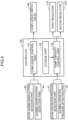
- FIG. 6 is a flowchart showing an arithmetic control operation executed by the controller 50.
- the controller 50 starts the hydraulic excavator 100 upon receiving an input of a signal associated with a turn of a start key on by the operator in a cab of the hydraulic excavator 100 (Step S1).
- the controller 50 reads various signals to be input from a plurality of sensors to the controller 50 (Step S2).
- the controller 50 outputs various instruction signals to operate the hydraulic excavator 100 on the basis of various read signals (Step S3). Consequently, various operations are executed by the hydraulic excavator 100.
- the confluence control part 51 of the controller 50 determines whether the boom raising manipulation is applied to the boom control device 20 (Step S4). Specifically, when no boom raising pilot pressure detection signal is input from the boom raising manipulation detection part 43 to the controller 50, the confluence control part 51 determines that the boom raising manipulation is not performed (NO in Step S4), and outputs, to a solenoid 80a of the confluence pilot valve 80, an instruction signal that instructs not to supply the pilot pressure to the acceleration pilot port 40a. Consequently, no hydraulic fluid discharged from the pilot pump 13 is input to the acceleration pilot port 40a of the confluence switch valve 40. The confluence switch valve 40 is thus placed at the neutral position, i.e., in the suspension state (Step S9).
- the confluence control part 51 determines that the boom raising manipulation is performed (YES in Step S4).
- the confluence control part 51 determines whether the slewing manipulation is applied to the slewing control device 30 (Step S5). Specifically, when no slewing pilot pressure detection signal is input from the slewing manipulation detection part 44 to the controller 50, the confluence control part 51 determines that the slewing manipulation is not performed (NO in Step S5).
- Step S5 the operator performs the non-slewing and boom raising manipulation action in which the boom raising manipulation is performed but the slewing manipulation is not performed.
- the confluence control part 51 outputs the instruction signal corresponding to the boom raising pilot pressure detection signal.
- the instruction signal is input to the solenoid 80a of the confluence pilot valve 80. Consequently, the pressure of the hydraulic fluid discharged from the pilot pump 13 is reduced to a pilot pressure corresponding to the boom raising pilot pressure detection signal at the confluence pilot valve 80, and the pilot pressure is input to the acceleration pilot port 40a of the confluence switch valve 40.
- the confluence switch valve 40 shifts from the neutral position to the boom raising acceleration position in a stroke commensurate with a magnitude of the pilot pressure. Specifically, the confluence switch valve 40 is switched to the permission state (Step S8).
- the confluence control part 51 determines that the slewing manipulation is performed (YES in Step S5).
- Step S5 the operator performs the slewing and boom raising manipulation action in which the boom raising manipulation is performed and the slewing manipulation is concurrently performed.
- the confluence control part 51 outputs to the solenoid 80a of the confluence pilot valve 80 the instruction signal that instructs not to supply the pilot pressure to the acceleration pilot port 40a. Consequently, no hydraulic fluid discharged from the pilot pump 13 is input to the acceleration pilot port 40a of the confluence switch valve 40.
- the confluence switch valve 40 is thus at the neutral position, i.e., in the suspension state (Step S6).
- the pump capacity control part 52 of the controller 50 executes the capacity control on the basis of the operating pressure difference, i.e., a value obtained by subtracting the slewing operating pressure detected by the slewing operating pressure detection part 42 from the boom operating pressure detected by the boom operating pressure detection part 41.
- the pump capacity control part 52 outputs a first capacity instruction signal for setting the first pump capacity to a pump capacity corresponding to the operating pressure difference in the map shown in FIG. 5 , and outputs a second capacity instruction signal for setting the second pump capacity to a pump capacity corresponding to the operating pressure difference in the map (Step S7).
- the first pump capacity is regulated to a capacity corresponding to the first capacity instruction signal
- the second pump capacity is regulated to a capacity corresponding to the second capacity instruction signal.
- FIG. 7 is a block diagram showing a configuration of the controller 50 connected to a hydraulic circuit in a hydraulic excavator which is a modification of the embodiment.
- FIG. 8 is a graph showing an exemplary map stored in a storage part 53 of the controller 50 in the modification.
- the modified hydraulic excavator differs from the hydraulic excavator 100 according to the embodiment described above with reference to FIGS. 1 to 6 in that it further includes a leading end attachment determination part having an image taking device 47 and an image determination section 54 as shown in FIG. 7 . Further, the modified hydraulic excavator differs from the hydraulic excavator 100 according to the embodiment described above with reference to FIGS. 1 to 6 in that the storage part 53 stores a plurality of maps as shown in FIG. 8 .
- the differences will be mainly described. Apart from the differences, the configuration of the modified hydraulic excavator is the same as the configuration of the hydraulic excavator 100 according to the embodiment shown in FIGS. 1 to 6 .
- the image taking device 47 acquires a site image that is an image of a work site where the hydraulic excavator 100 works.
- the site image is an image including at least the leading end attachment (the leading end attachment actually included in the working device 3).
- Image data acquired by the image taking device 47 is input to the controller 50.
- the image determination section 54 determines, on the basis of the image data input to the controller 50, which leading end attachment among the leading end attachments 6, 6A, 6B, 6C, and 6D is actually included in the working device 3.
- the image determination section 54 may determine the leading end attachment included in the working device 3 by detecting the leading end attachment included in the image through, for example, Template Matching. Further, the image determination section 54 may determine which leading end attachment among the leading end attachments 6, 6A, 6B, 6C, and 6D coincides with the leading end attachment included in the site image by inputting the image data to a multilayered neural network machine-learned through Deep Learning. Further, the image determination section 54 may determine the leading end attachment included in the working device 3 on the basis of a marker for recognition disposed in advance on each of the leading end attachments.
- a map is individually drawn in advance for each of the leading end attachments 6, 6A, 6B, 6C, and 6D as shown in FIG. 8 .
- the maps respectively corresponding to the leading end attachments 6, 6A, 6B, 6C, and 6D are drawn such that a straight line representing a relationship between the operating pressure difference and the first pump capacity q1 has a gradient smaller as the weight of the leading end attachment increases.
- the maps are drawn such that a straight line representing a relationship between the operating pressure difference and the second pump capacity q2 has a gradient greater (i.e., such that the gradient denoting a negative value has a smaller absolute value) as the weight of the leading end attachment increases.
- the modification including the maps drawn as shown in FIG. 8 can prevent an occurrence of a situation where the second pump capacity excessively decreases due to an increase in the operating pressure difference caused by a leading end attachment having a relatively large weight selectively mounted among the leading end attachments when the upper slewing body 2 reaches the steady slew state.
- the maps are not limited to the specific one shown in FIG. 8 , but may be properly drawn in such a manner as to prevent a change in the balance between an operation of a slewing motor and an operation of a boom cylinder when the slewing and boom raising manipulation action is performed due to a variation in the weight of the working device.
- a restriction for a horsepower control is likely to be relieved, consequently increasing, in this case, a degree of freedom in the setting of a map.
- a work content is variable depending on the type of the leading end attachment. Therefore, the maps may be drawn in consideration of these factors.
- the pump capacity control part 52 outputs the capacity instruction signals for setting the first pump capacity and the second pump capacity to respective pump capacities corresponding to the operating pressure difference on the basis of the map that corresponds to the leading end attachment determined, among the maps, by the image determination section 54.
- the modification in which a map is drawn for each of the leading end attachments having different weights from one another, enables a more finely calibrated capacity control optimal for a weight of each of the leading end attachments. Additionally, in the modification, the leading end attachment actually included in the working device 3 is determined by the leading end attachment determination part. Therefore, for example, the leading end attachment can be identified through the determination by the leading end attachment determination part without requiring the operator of the hydraulic excavator 100 to perform an input work for identifying the leading end attachment included in the working device 3. This enables a reduction of burden on the operator.
- the present invention is not limited to the embodiments described above.
- the present invention may include the following configurations, for example.
- the slewing-type construction machine is the hydraulic excavator 100, but it is not limited thereto.
- This invention may be applicable to a wide range of construction machines which include an upper slewing body slewably mounted on a base body and utilize hydraulic fluid as a main drive power.
- the base body is not limited to the self-propellable one, e.g., a lower travelling body of the hydraulic excavator 100, but may be a member fixedly attached to the ground or a structure.
- the map is drawn such that each of the first pump capacity q1 and the second pump capacity q2 has a constant value in a region where the operating pressure difference is equal to or smaller than a preset value Pc as shown in FIG. 5 , but is not limited to this configuration.
- the map may be drawn such that the first pump capacity q1 increases and the second pump capacity q2 decreases as the operating pressure difference increases in the region where the operating pressure difference is equal to or smaller than the preset value Pc as well.
- the map is drawn such that the first pump capacity q1 is larger than the second pump capacity q2 in the region where the operating pressure difference is equal to or smaller than the preset value Pc as shown in FIG. 5 , but is not limited to this configuration.
- the map may be drawn such that the first pump capacity q1 is smaller than the second pump capacity q2, or such that the first pump capacity q1 has the same value as the second pump capacity q2 in the region where the operating pressure difference is equal to or smaller than the preset value Pc.
- the map is drawn such that the relationship (characteristics) between the operating pressure difference, the first pump capacity q1, and the second pump capacity q2 is represented by a straight line as shown in FIG. 5 , but is not limited to this configuration, and may be properly drawn according to characteristics of a target construction machine.
- the map may be drawn such that the relationship (characteristics) between the operating pressure difference, the first pump capacity q1, and the second pump capacity q2 is represented by a curve, or such that the relationship (characteristics) is represented by a combination of a straight line and a curve.
- a map is individually drawn for each of the leading end attachments 6, 6A, 6B, 6C, and 6D, but the map is not limited to this configuration.
- a map (first map) representing a relationship between the operating pressure difference, the first pump capacity, and the second pump capacity in one leading end attachment (first leading end attachment) among the leading end attachments 6, 6A, 6B, 6C, and 6D is drawn in advance
- a map (second map) representing a relationship between the operating pressure difference, the first pump capacity, and the second pump capacity in another leading end attachment (second leading end attachment) among the leading end attachments 6, 6A, 6B, 6C, and 6D is drawn in advance.
- a map is not particularly required to be drawn, and the first map or the second map may be used.
- the leading end attachment determination part includes the image taking device 47 and the image determination section 54, but is not limited to this configuration.
- the leading end attachment determination part may include, for example, a reception section for receiving an input by the operator of the construction machine for identifying the leading end attachment included in the working device, and an input information determination section for determining on the basis of the input information received by the reception section which of the leading end attachments is included.
- the slewing-type construction machine includes the confluence pilot valve 80 (solenoid valve).
- the confluence pilot valve 80 is not essential, but is omittable. In a case of the omission of the confluence pilot valve 80, when the boom raising manipulation is applied to the boom manipulating lever 23, a pilot pressure from the boom remote control valve 24 may be input to the acceleration pilot port 40a of the confluence switch valve 40.
- the control valve is placed in the permission state when no pilot pressure is input from the slewing remote control valve 34, i.e., when the non-slewing and boom raising manipulation action is performed, and the control valve is switched to the suspension state when a pilot pressure is input from the slewing remote control valve 34, i.e., when the slewing and boom raising manipulation action is performed.
- This modification enables a cost reduction owing to the omission of the solenoid valve.
- the boom control device and the slewing control device include hydraulic control devices (hydraulic operation devices), but are not limited thereto, and may include electric control devices (electric operation devices).
- hydraulic control devices hydraulic operation devices
- electric control devices electric operation devices
- the manipulating levers 23, 33 when the manipulating levers 23, 33 are manipulated, primary pilot pressures from the pilot pump 13 are reduced according to respective manipulation amounts of the manipulating levers, and the reduced pilot pressures are thus output from the remote control valves 24, 34.
- the output pilot pressures are input to the pilot ports of the control valves 21, 31.
- the respective manipulation amounts of the manipulating levers 23, 33 are converted into electric signals, and are input to the controller 50.
- the controller 50 inputs instruction currents commensurate with the respective operation amounts to proportional solenoid valves.
- the proportional solenoid valves are arranged between the pilot pump 13 and a pair of pilot ports of each of the control valves 21, 31.
- the proportional solenoid valves allows pilot pressures corresponding to the instruction currents to flow
- a slewing-type construction machine that can keep the balance between an operation of a slewing motor and an operation of a boom cylinder from changing when a slewing and boom raising manipulation action is performed, irrespective of a change in the weight of a working device caused by a replacement of a leading end attachment.
- a slewing-type construction machine to be provided includes: a base body; an upper slewing body slewably mounted on the base body; a working device including a boom tiltably connected to the upper slewing body, and a leading end attachment that is selected from a plurality of leading end attachments having different weights from one another; a first hydraulic pump having a variable capacity for discharging hydraulic fluid; a second hydraulic pump having a variable capacity for discharging hydraulic fluid; a boom cylinder receiving a supply of the hydraulic fluid discharged from the first hydraulic pump to raise and lower the boom; a boom control device, in response to a boom raising manipulation causing the boom to move in a rising direction, controlling a flow rate of the hydraulic fluid supplied from the first hydraulic pump to the boom cylinder; a slewing motor receiving a supply of the hydraulic fluid discharged from the second hydraulic pump to slew the upper slewing body; a slewing control device, in response to a slewing manipulation causing the upper slewing
- the confluence switch valve is set in the permission state when the non-slewing and boom raising manipulation action, in which the boom raising manipulation is performed but the slewing manipulation is not performed, is performed. Therefore, at least a part of hydraulic fluid discharged from the second hydraulic pump flows together with hydraulic fluid supplied from the first hydraulic pump to the boom cylinder. Consequently, the boom raising operation is accelerated.
- the confluence switch valve is set in the suspension state when the slewing and boom raising manipulation action is performed. Therefore, the hydraulic fluid discharged from the second hydraulic pump is kept from flowing together with the hydraulic fluid supplied from the first hydraulic pump to the boom cylinder.
- a slewing motor side circuit being a circuit connecting the second hydraulic pump and the slewing motor is isolated from a boom cylinder side circuit being a circuit connecting the first hydraulic pump and the boom cylinder.
- the following control is executed when the slewing and boom raising manipulation action is performed in order to facilitate the maintenance of a balance between an operation of the boom cylinder and an operation of the slewing motor when the slewing and boom raising manipulation action is performed.
- the first pump capacity and the second pump capacity are regulated on the basis of the operating pressure difference when the slewing and boom raising manipulation action is performed.
- the first pump capacity and the second pump capacity are respectively regulated in such a manner that the first pump capacity increases and the second pump capacity decreases as the operating pressure difference increases, and in such a manner that the first pump capacity decreases and the second pump capacity increases as the operating pressure difference decreases.
- the hydraulic fluid is supplied from the first pump and the second hydraulic pump to the boom cylinder and the slewing motor at flow rates responsive to the respective loads applied to the boom cylinder and the slewing motor.
- This consequently facilitates the maintenance of a balance between an operation of the boom cylinder and an operation of the slewing motor when the slewing and boom raising manipulation action is performed.
- the first pump capacity and the second pump capacity are regulated on the basis of the operating pressure difference upon separation of the slewing motor side circuit from the boom cylinder side circuit when the slewing and boom raising manipulation action is performed.
- the balance between an operation of the slewing motor and an operation of the boom cylinder can be kept from changing when the slewing and boom raising manipulation action is performed, irrespective of a change in the weight of the working device due to a replacement of the leading end attachment.
- the slewing-type construction machine further includes a storage part for storing at least one map representing a preset relationship between the operating pressure difference, the first pump capacity, and the second pump capacity, and the pump capacity control part regulates, in the capacity control, the first pump capacity and the second pump capacity to respective pump capacities corresponding to the operating pressure difference using the at least one map.
- the first pump capacity and the second pump capacity are respectively regulated according to an increase and a decrease in the operating pressure difference on the basis of the at least one preset map when the slewing and boom raising manipulation action is performed. This enables a stable execution of the capacity control according to the at least one map.
- the leading end attachments include a first leading end attachment and a second leading end attachment having different weights from one another
- the at least one map includes a first map on the first leading end attachment representing a preset relationship between the operating pressure difference, the first pump capacity, and the second pump capacity, and a second map on the second leading end attachment representing a preset relationship between the operating pressure difference, the first pump capacity, and the second pump capacity
- the pump capacity control part executes the capacity control using the first map when the working device includes the first leading end attachment, and executes the capacity control using the second map when the working device includes the second leading end attachment.
- the slewing-type construction machine further includes a leading end attachment determination part for determining which of the first leading end attachment and the second leading end attachment the working device includes, and the pump capacity control part executes the capacity control using either the first map or the second map that corresponds to a leading end attachment determined to be included in the working device by the leading end attachment determination part.
- the leading end attachment actually included in the working device is determined by the leading end attachment determination part. Therefore, for example, the leading end attachment can be identified through the determination by the leading end attachment determination part without requiring the operator of the construction machine to perform an input work for identifying the leading end attachment included in the working device. This enables a reduction of burden on the operator.
- the leading end attachment determination part includes an image taking device for taking an image including the leading end attachment included in the working device, and an image determination section for determining, on the basis of the image taken by the image taking device, which of the first leading end attachment and the second leading end attachment is included.
- the image determination section can determine the leading end attachment actually included in the working device on the basis of the image taken by the image taking device.
Landscapes
- Engineering & Computer Science (AREA)
- General Engineering & Computer Science (AREA)
- Structural Engineering (AREA)
- Mining & Mineral Resources (AREA)
- Civil Engineering (AREA)
- Mechanical Engineering (AREA)
- Physics & Mathematics (AREA)
- Fluid Mechanics (AREA)
- Operation Control Of Excavators (AREA)
- Fluid-Pressure Circuits (AREA)
Abstract
Description
- The present invention relates to a slewing-type construction machine such as a hydraulic excavator.
- For example, as disclosed in
Patent Literature 1, a slewing-type construction machine such as a hydraulic excavator generally includes a lower travelling body, an upper slewing body slewably mounted on the lower travelling body, a working device including a boom tiltably connected to the upper slewing body, a boom cylinder receiving a supply of hydraulic oil discharged from a first hydraulic pump to raise and lower the boom, a slewing motor receiving a supply of the hydraulic fluid discharged from a second hydraulic pump to slew the upper slewing body, and a confluence switch valve (a boom-accelerating control valve) permitting a confluence of a part of the hydraulic fluid discharged from the second pump with the hydraulic fluid supplied from the first hydraulic pump to the boom cylinder to thereby accelerate the boom raising operation. - In the construction machine of
Patent Literature 1, the confluence switch valve is switched to permit a confluence of a part of the hydraulic fluid discharged from the second pump with the hydraulic fluid supplied from the first hydraulic pump to the boom cylinder when a slewing and boom raising manipulation action is performed, the slewing and boom raising manipulation action including the slewing manipulation and the boom raising manipulation. - In a hydraulic control circuit in a construction machine of
Patent Literature 2, when boom raising detection means and slewing detection means detect a combined operation of the boom raising and slewing, a flow rate distribution control part controls a regulator so that a first pump has a discharge flow rate higher than a second pump at a start of the combined operation, and controls the regulator so as to reduce a discharge flow difference as a difference between the respective pump discharge pressures detected by first pump pressure detection means and second pump pressure detection means increases after the slewing becomes steady. - Generally, the working device in the slewing-type construction machine as described above includes a leading end attachment that is selected from a plurality of leading end attachments that are a bucket, a grapple, a crusher, a breaker, a fork, and the like. Specifically, the leading end attachments are configured to be replaceable with one another according to the work content.
- The conventional slewing-type construction machine as described above involves a problem that replacement of a leading end attachment of the working device with another leading end attachment having a weight different from that of the former leading end attachment changes the weight of the working device, and consequently leads to an unbalance between the operation of the boom cylinder and the operation of the slewing motor when the slewing and boom raising manipulation action is performed. A specific explanation will be made below.
- For example, when a leading end attachment of the working device is replaced with another leading end attachment having a weight higher than that of the former leading end attachment, the weight of the working device increases, and then the operating pressure of the boom cylinder rises compared with that before the replacement of the leading end attachment. As a result, when the slewing and boom raising manipulation action is performed, the operating pressure of the slewing motor rises as well. When the operating pressure of the slewing motor rises, the acceleration rate of the slewing motor rises. Specifically, in the conventional slewing-type construction machine, when the slewing and boom raising manipulation action is performed, the operation of the slewing motor is considerably affected by the operating pressure rise in the boom cylinder that is caused by an increase in the weight of the working device.
-
- Patent Literature 1:
Japanese Unexamined Patent Publication No. SHO 62-253825 - Patent Literature 2:
Japanese Unexamined Patent Publication No. 2005-83427 - An object of the present invention is to provide a slewing-type construction machine that can keep the balance between an operation of a slewing motor and an operation of a boom cylinder from changing when a slewing and boom raising manipulation action is performed, irrespective of a change in the weight of a working device caused by a replacement of a leading end attachment.
- A slewing-type construction machine to be provided includes: a base body; an upper slewing body slewably mounted on the base body; a working device including a boom tiltably connected to the upper slewing body, and a leading end attachment that is selected from a plurality of leading end attachments having different weights from one another; a first hydraulic pump having a variable capacity for discharging hydraulic fluid; a second hydraulic pump having a variable capacity for discharging hydraulic fluid; a boom cylinder receiving a supply of the hydraulic fluid discharged from the first hydraulic pump to raise and lower the boom; a boom control device, in response to a boom raising manipulation causing the boom to move in a rising direction, controlling a flow rate of the hydraulic fluid supplied from the first hydraulic pump to the boom cylinder; a slewing motor receiving a supply of the hydraulic fluid discharged from the second hydraulic pump to slew the upper slewing body; a slewing control device, in response to a slewing manipulation causing the upper slewing body to slew, controlling a direction and a flow rate of the hydraulic fluid supplied from the second hydraulic pump to the slewing motor; a confluence switch valve switchable between a permission state of permitting a confluence of at least a part of the hydraulic fluid discharged from the second hydraulic pump with the hydraulic fluid supplied from the first hydraulic pump to the boom cylinder and a suspension state of suspending the confluence of the hydraulic fluid; a boom operating pressure detection part for detecting a boom operating pressure corresponding to an operating pressure of the boom cylinder; a slewing operating pressure detection part for detecting a slewing operating pressure corresponding to an operating pressure of the slewing motor; a confluence control part for controlling the confluence switch valve to be in the permission state when a non-slewing and boom raising manipulation action in which the boom raising manipulation is applied to the boom control device and the slewing manipulation is not applied to the slewing control device is performed, and controlling the confluence switch valve to be in the suspension state when a slewing and boom raising manipulation action in which the boom raising manipulation is applied to the boom control device and the slewing manipulation is concurrently applied to the slewing control device is performed; and a pump capacity control part for executing a capacity control when the slewing and boom raising manipulation action is performed, the capacity control including a control of regulating a first pump capacity meaning a pump capacity of the first hydraulic pump and a second pump capacity meaning a pump capacity of the second hydraulic pump respectively in such a manner that the first pump capacity increases and the second pump capacity decreases as an operating pressure difference resulting from the subtraction of the slewing operating pressure from the boom operating pressure increases, and a control of regulating the first pump capacity and the second pump capacity respectively in such a manner that the first pump capacity decreases and the second pump capacity increases as the operating pressure difference decreases.
-
-
FIG. 1 is a side view showing a slewing-type construction machine according to an embodiment, the slewing-type construction machine including a bucket as a leading end attachment. -
FIG. 2 shows other exemplary leading end attachments. -
FIG. 3 is a diagram showing a hydraulic circuit included in the slewing-type construction machine. -
FIG. 4 is a block diagram showing a configuration of a controller connected to the hydraulic circuit. -
FIG. 5 is a graph showing an exemplary map stored in a storage part of the controller. -
FIG. 6 is a flowchart showing an arithmetic control operation executed by the controller. -
FIG. 7 is a block diagram showing a configuration of a controller connected to a hydraulic circuit in a slewing-type construction machine which is a modification of the embodiment. -
FIG. 8 is a graph showing another exemplary map stored in a storage part of the controller in the modification. - Hereinafter, an embodiment of the present invention will be described with reference to the drawings.
FIG. 1 is a side view showing ahydraulic excavator 100, which is an exemplary slewing-type construction machine according to the embodiment. - The
hydraulic excavator 100 includes alower travelling body 1 capable of travelling on the ground, anupper slewing body 2 mounted on thelower travelling body 1 slewably about a vertical axis Z, and a workingdevice 3 mounted on theupper slewing body 2. A front portion of theupper slewing body 2 in a front-rear direction is provided with a cab serving as an operating room, and is mounted with theworking device 3, whereas a rear portion is provided with an engine room and is mounted with a counterweight. - The
working device 3 includes aboom 4, anarm 5, and a leading end attachment that is selected from a plurality of leading end attachments. Thehydraulic excavator 100 further includes aboom cylinder 7, anarm cylinder 8, and a leadingend attachment cylinder 9. - The
boom 4 includes a base end portion supported at a front end of theupper slewing body 2 tiltably, i.e., swingably in an upper and lower direction about a horizontal axis, and a leading end portion on the opposite thereto. Thearm 5 includes a base end portion connected to the leading end portion of theboom 4 swingably about the horizontal axis, and a leading end portion on the opposite thereto. - The leading end attachments include, for example, a
bucket 6 shown inFIG. 1 , and agrapple 6A, acrusher 6B, abreaker 6C, and afork 6D that are shown inFIG. 2 . The leadingend attachments end attachments working device 3. Since the leadingend attachments - The
bucket 6 shown inFIG. 1 is a leading end attachment adapted for performing, for example, an excavation work in a work site. Thebucket 6 is swingably attached to the leading end portion of thearm 5. - The
grapple 6A shown inFIG. 2 is a leading end attachment adapted for gripping and transporting scrap in a scrapyard and the like, for example. Thegrapple 6A has abracket 61A attached to the leading end portion of thearm 5, a grapplemain body 62A supported by thebracket 61A, and a plurality ofclaws 63A (fourclaws 63A inFIG. 2 ) supported by the grapplemain body 62A. - The
crusher 6B is a leading end attachment adapted for performing a demolishing work of a concrete building and the like, for example. Thecrusher 6B has abracket 61B attached to the leading end portion of thearm 5, a crushermain body 62B supported by thebracket 61B, and a pair of crushingarms 63B supported by the crushermain body 62B. - The
breaker 6C is a leading end attachment adapted for excavating bedrock, splitting rock, and crushing concrete, and the like, for example. Thebreaker 6C has abracket 61C attached to the leading end portion of thearm 5, a breakermain body 62C supported by thebracket 61C, and achisel 63C that is supported by the breakermain body 62C and is reciprocable in the axial directions thereof. - The
fork 6D is a leading end attachment adapted for gripping an object to be transported, for example. Thefork 6D has abracket 61D attached to the leading end portion of thearm 5, a forkmain body 62D supported by thebracket 61D, and a pair of opening and closingarms 63D supported by the forkmain body 62D. -
FIG. 3 is a diagram showing a hydraulic circuit included in thehydraulic excavator 100.FIG. 4 is a block diagram showing a configuration of acontroller 50 connected to the hydraulic circuit. As shown inFIGS. 3 and4 , thehydraulic excavator 100 includes a first hydraulic pump 11, a secondhydraulic pump 12, apilot pump 13, afirst regulator 11A, asecond regulator 12A, aboom control device 20, aslewing motor 10, aslewing control device 30, aconfluence switch valve 40, aconfluence pilot valve 80, an arm control device, a leading endattachment control device 70, a boom operatingpressure detection part 41, a slewing operatingpressure detection part 42, a boom raisingmanipulation detection part 43, a slewingmanipulation detection part 44, a leading end attachmentmanipulation detection part 45, and acontroller 50. - Each of the first hydraulic pump 11 and the second
hydraulic pump 12 is a variable capacity hydraulic pump, in which the pump capacity is regulable. Thefirst regulator 11A regulates, in response to an input of a capacity instruction signal that is an electric signal from thecontroller 50, a first pump capacity meaning a pump capacity of the first hydraulic pump 11 to a capacity corresponding to the capacity instruction signal. Similarly, thesecond regulator 12A regulates, in response to an input of a capacity instruction signal that is an electric signal from thecontroller 50, a second pump capacity meaning a pump capacity of the secondhydraulic pump 12 to a capacity corresponding to the capacity instruction signal. The first hydraulic pump 11, the secondhydraulic pump 12, and thepilot pump 13 are driven by an unillustrated engine to thereby respectively discharge the hydraulic fluid in a tank. - The
boom cylinder 7 is a hydraulic actuator that operates to raise and lower theboom 4 upon receiving a supply of hydraulic fluid discharged from the first hydraulic pump 11. Theboom cylinder 7 has abottom chamber 7a and arod chamber 7b on the opposite thereto. Theboom cylinder 7 extends upon a supply of the hydraulic fluid to thebottom chamber 7a to move theboom 4 in the boom raising direction, and concurrently discharge the hydraulic fluid from therod chamber 7b. Conversely, theboom cylinder 7 retracts upon a supply of the hydraulic fluid to therod chamber 7b to move theboom 4 in a boom lowering direction, and concurrently discharge the hydraulic fluid from thebottom chamber 7a. - The
boom control device 20 controls, in response to either a boom raising manipulation causing theboom 4 to move in a rising direction or a boom lowering manipulation operation causing theboom 4 to move in a lowering direction, a direction and a flow rate of the hydraulic fluid supplied from the first hydraulic pump 11 to theboom cylinder 7. Theboom control device 20 includes aboom control valve 21 and a boom manipulating device 22. - The
boom control valve 21 is arranged between the first hydraulic pump 11 and theboom cylinder 7, and is opened and closed in such a manner as to change the direction and the flow rate of the hydraulic fluid supplied from the first hydraulic pump 11 to theboom cylinder 7. Specifically, theboom control valve 21 includes a pilot-operated three-position directional switch valve including a boom raisingpilot port 21a and a boom loweringpilot port 21b. - When no pilot pressure is input to either the boom raising
pilot port 21a or the boom loweringpilot port 21b, theboom control valve 21 is kept at a neutral position, and blocks the flow of the hydraulic fluid in a fluid passage between the first hydraulic pump 11 and theboom cylinder 7. The fluid passage between the first hydraulic pump 11 and theboom control valve 21 is provided with an unillustrated relief valve. - When a boom raising pilot pressure is input to the boom raising
pilot port 21a, theboom control valve 21 shifts from the neutral position to a boom raising position in a stroke commensurate with a magnitude of the boom raising pilot pressure. The valve is thus opened in such a manner as to permit the supply of the hydraulic fluid from the first hydraulic pump 11 to thebottom chamber 7a of theboom cylinder 7 at a flow rate corresponding to the stroke, and the discharge of the hydraulic fluid from therod chamber 7b of theboom cylinder 7. This drives theboom cylinder 7 in the boom raising direction at a speed corresponding to the boom raising pilot pressure. - When a boom lowering pilot pressure is input to the boom lowering
pilot port 21b, theboom control valve 21 shifts from the neutral position to a boom lowering position in a stroke commensurate with a magnitude of the boom lowering pilot pressure. The valve is thus opened in such a manner as to permit the supply of the hydraulic fluid from the first hydraulic pump 11 to therod chamber 7b of theboom cylinder 7 at a flow rate corresponding to the stroke, and the discharge of the hydraulic fluid from thebottom chamber 7a of theboom cylinder 7. This drives theboom cylinder 7 in the boom lowering direction at a speed corresponding to the boom lowering pilot pressure. - The boom manipulating device 22 operates, in response to either the boom raising manipulation causing the
boom 4 to move in the rising direction or the boom lowering manipulation causing theboom 4 to move in the lowering direction, in such a manner as to permit the input of the pilot pressure corresponding to the manipulation from thepilot pump 13 to theboom control valve 21. - Specifically, the boom manipulating device 22 includes a boom manipulating lever 23 and a boom remote control valve 24.
- The boom manipulating lever 23 is a member rotatable in response to either the boom raising manipulation or the boom lowering manipulation by an operator. The boom raising manipulation and the boom lowering manipulation cause the boom manipulating lever 23 to rotate in directions opposite to each other.
- The boom remote control valve 24 is a pilot valve that is arranged between the
pilot pump 13 and the pair ofpilot ports FIG. 3 , an illustration of a fluid passage connecting thepilot pump 13 and the boom remote control valve 24 is omitted. - When the boom manipulating lever 23 is not operated and is placed at a neutral position, the boom remote control valve 24 is closed to block the flow of the hydraulic fluid in the fluid passage between the
pilot pump 13 and the pair ofpilot ports pilot pump 13 to one of the pair ofpilot ports boom control valve 21 that corresponds to a direction of the one manipulation. - The slewing
motor 10 is a hydraulic motor that operates to slew theupper slewing body 2 upon receiving a supply of the hydraulic fluid discharged from the secondhydraulic pump 12. The slewingmotor 10 has an unillustrated output shaft that rotates upon receiving the supply of the hydraulic fluid discharged from the secondhydraulic pump 12, and the output shaft is connected to theupper slewing body 2 to slew theupper slewing body 2 to both the directions or leftward and rightward. Specifically, the slewingmotor 10 has afirst port 10a and asecond port 10b, receives the supply of the hydraulic fluid at one of the ports to rotate the output shaft in a direction corresponding to the one port, and discharge the hydraulic fluid from the other port. - The slewing
control device 30 controls, in response to a slewing manipulation causing theupper slewing body 2 to slew, the direction and flow rate of the hydraulic fluid supplied from the secondhydraulic pump 12 to the slewingmotor 10. The slewingcontrol device 30 includes a slewingcontrol valve 31 and aslewing manipulating device 32. - The slewing
control valve 31 is arranged between the secondhydraulic pump 12 and the slewingmotor 10. The slewingcontrol valve 31 selectively directs the hydraulic fluid used to drive the slewingmotor 10 from the secondhydraulic pump 12 to either thefirst port 10a or thesecond port 10b of the slewingmotor 10, and controls a slewing flow rate meaning a flow rate of the hydraulic fluid supplied to the slewingmotor 10. The slewingcontrol valve 31 is a three-position pilot switch valve, and has a pair of slewingpilot ports 31a, 31b. - When the pilot pressures supplied to the pair of slewing
pilot ports 31a, 31b are zero or minute, the slewingcontrol valve 31 is kept at a neutral position, and blocks the flow of the hydraulic fluid in a fluid passage between the secondhydraulic pump 12 and the slewingmotor 10. The fluid passage between the secondhydraulic pump 12 and the slewingcontrol valve 31 is provided with an unillustrated relief valve. - When a certain pilot pressure or more is supplied to one of the pair of slewing
pilot ports 31a, 31b, the slewingcontrol valve 31 shifts from the neutral position to a direction corresponding to the slewing pilot port in a stroke commensurate with a magnitude of the pilot pressure. This causes the slewingmotor 10 to operate in a direction and at a speed corresponding the stroke. - The
slewing manipulating device 32 operates, in response to a slewing manipulation causing theupper slewing body 2 to slew, in such a manner as to permit that the pilot pressure corresponding to the slewing manipulation is selectively supplied from thepilot pump 13 to either one of the pair of slewingpilot ports 3 1a, 3 1b of the slewingcontrol valve 31. - Specifically, the
slewing manipulating device 32 includes a slewing manipulating lever 33 and a slewingremote control valve 34. - The slewing manipulating lever 33 is a member rotatable in response to the slewing manipulation by an operator.
- The slewing
remote control valve 34 is a pilot valve arranged between thepilot pump 13 and the pair of slewingpilot ports 31a, 31b. InFIG. 3 , an illustration of a fluid passage connecting thepilot pump 13 and the slewingremote control valve 34 is omitted. - When the slewing manipulating lever 33 is not operated and is placed at a neutral position, the slewing
remote control valve 34 is closed to block the flow of the hydraulic fluid in the fluid passage between thepilot pump 13 and the pair of slewingpilot ports 31a, 31b. On the other hand, when the slewing manipulation is applied to the slewing manipulating lever 33, the slewingremote control valve 34 is opened in such a manner as to permit the input of a pilot pressure commensurate with the slewing manipulation from thepilot pump 13 to one of the pair of slewingpilot ports 31a, 31b of the slewingcontrol valve 31 that corresponds to a direction of the slewing manipulation. - The confluence switch
valve 40 is configured to be switchable between a permission state of permitting a confluence of at least a part of the hydraulic fluid discharged from the secondhydraulic pump 12 with the hydraulic fluid supplied from the first hydraulic pump 11 to thebottom chamber 7a of theboom cylinder 7 and a suspension state of suspending the confluence of the hydraulic fluid discharged from the secondhydraulic pump 12 with the hydraulic fluid supplied from the first hydraulic pump 11 to thebottom chamber 7a of theboom cylinder 7. - The confluence switch
valve 40 is configured to direct the hydraulic fluid used to accelerate the movement of theboom 4 in the rising direction, in addition to the hydraulic fluid supplied from the first hydraulic pump 11 to thebottom chamber 7a of theboom cylinder 7, from the secondhydraulic pump 12 to thebottom chamber 7a of theboom cylinder 7, and to regulate the flow rate of the hydraulic fluid. - The confluence switch
valve 40 is a two-position pilot switch valve, and has oneacceleration pilot port 40a. When the pilot pressure supplied to theacceleration pilot port 40a is zero or minute, theconfluence switch valve 40 is kept at a neutral position, and blocks the flow of the hydraulic fluid in a fluid passage between the secondhydraulic pump 12 and theboom cylinder 7. When a certain pilot pressure or more is supplied to theacceleration pilot port 40a, theconfluence switch valve 40 shifts from the neutral position to a boom raising acceleration position in a stroke commensurate with a magnitude of the pilot pressure. This allows at least a part of the hydraulic fluid from the secondhydraulic pump 12 to flow, at a flow rate corresponding to the stroke, together with the hydraulic fluid supplied from the first hydraulic pump 11 to thebottom chamber 7a, to be thereby supplied to thebottom chamber 7a of theboom cylinder 7. This accelerates the drive of theboom cylinder 7 in the boom raising direction (rising direction) with an intensity commensurate with the stroke. - The
confluence pilot valve 80 includes, for example, a solenoid valve (e.g., a proportional pressure reducing valve or an inversely proportional pressure reducing valve) having asolenoid 80a, and is configured to reduce the pressure of the hydraulic fluid discharged from thepilot pump 13 to a pressure corresponding to an instruction signal (electric signal) input to thesolenoid 80a, and to input the reduced pressure to theacceleration pilot port 40a of theconfluence switch valve 40. - The
arm cylinder 8 shown inFIG. 1 is a hydraulic actuator that operates to raise and lower thearm 5 upon receiving a supply of hydraulic fluid discharged from the secondhydraulic pump 12. The leadingend attachment cylinder 9 shown inFIGS. 1 and3 is hydraulic actuator that operates to swing the leading end attachment upon receiving a supply of hydraulic fluid discharged from the first hydraulic pump 11. - The arm control device is a device adapted for operating the
arm 5. InFIG. 3 , an illustration of the arm control device is omitted. - The leading end
attachment control device 70 is a device adapted for operating a leading end attachment such as thebucket 6. The leading endattachment control device 70 controls, in response to a leading end attachment manipulation causing the leading end attachment included in the workingdevice 3 to swing, a direction and a flow rate of hydraulic fluid supplied from the first hydraulic pump 11 to the leadingend attachment cylinder 9. The leading endattachment control device 70 includes a leading endattachment control valve 71 and a leading endattachment manipulating device 72. - The leading end
attachment control valve 71 is arranged between the first hydraulic pump 11 and the leadingend attachment cylinder 9, and is opened and closed in such a manner as to change the direction and the flow rate of the hydraulic fluid supplied from the first hydraulic pump 11 to the leadingend attachment cylinder 9. Specifically, the leading endattachment control valve 71 includes three position direction change valve of a pilot operation type including a pair ofpilot ports - When no pilot pressure is input to the pair of
pilot ports attachment control valve 71 is kept at a neutral position, and blocks the flow of the hydraulic fluid in a fluid passage between the first hydraulic pump 11 and the leadingend attachment cylinder 9. The fluid passage between the first hydraulic pump 11 and the leading endattachment control valve 71 is provided with an unillustrated relief valve. - When a pilot pressure is input to either one of the pair of
pilot ports attachment control valve 71 shifts from the neutral position in a stroke commensurate with a magnitude of the pilot pressure to be thereby opened in such a manner as to permit the supply of the hydraulic fluid from the first hydraulic pump 11 to one of thebottom chamber 9a and therod chamber 9b of the leadingend attachment cylinder 9 at a flow rate corresponding to the stroke, and the discharge of the hydraulic fluid from the other of thebottom chamber 9a and therod chamber 9b of the leadingend attachment cylinder 9. This drives the leadingend attachment cylinder 9 at a speed corresponding to the pilot pressure. - The leading end
attachment manipulating device 72 operates, in response to an attachment manipulation causing the leading end attachment to operate, in such a manner as to permit the input of the pilot pressure corresponding to the attachment manipulation from thepilot pump 13 to the leading endattachment control valve 71. - Specifically, the leading end
attachment manipulating device 72 includes a leading endattachment manipulating lever 73 and a leading end attachmentremote control valve 74. - The leading end
attachment manipulating lever 73 is a member rotatable in response to the attachment manipulation by an operator. - The leading end attachment
remote control valve 74 is a pilot valve arranged between thepilot pump 13 and the pair ofpilot ports FIG. 3 , an illustration of a fluid passage connecting thepilot pump 13 and the leading end attachmentremote control valve 74 is omitted. - When the leading end
attachment manipulating lever 73 is not operated and is placed at a neutral position, the leading end attachmentremote control valve 74 is closed to block the flow of the hydraulic fluid in the fluid passage between thepilot pump 13 and the pair ofpilot ports attachment manipulating lever 73, the leading end attachmentremote control valve 74 is opened in such a manner as to permit the input of a pilot pressure commensurate with the manipulation amount of the attachment manipulation from thepilot pump 13 to one of the pair ofpilot ports attachment control valve 71 that corresponds to a direction of the attachment manipulation. - The boom operating
pressure detection part 41 detects a boom operating pressure corresponding to an operating pressure of theboom cylinder 7. In this embodiment, as the boom operatingpressure detection part 41, there is provided apressure sensor 41 capable of detecting a pressure in thebottom chamber 7a of theboom cylinder 7. The boom operatingpressure detection part 41 detects a pressure in a fluid passage between theboom control valve 21 and thebottom chamber 7a of theboom cylinder 7. Specifically, the boom operatingpressure detection part 41 may detect, for example, a pressure in the fluid passage at a position between a portion connected with a secondary side fluid passage of theconfluence switch valve 40 and thebottom chamber 7a. The boom operatingpressure detection part 41 generates a boom operating pressure detection signal corresponding to the pressure in thebottom chamber 7a of theboom cylinder 7. The boom operating pressure detection signal is input to thecontroller 50. - As the boom operating
pressure detection part 41, there may be provided, for example, apressure sensor 46 capable of detecting a discharge pressure of the first hydraulic pump 11. Thepressure sensor 46 may detect, for example, a pressure in a fluid passage connecting the first hydraulic pump 11 and theboom control valve 21 at a position between a portion connected with a primary side fluid passage of the leading endattachment control valve 71 and the first hydraulic pump 11. - The slewing operating
pressure detection part 42 detects a slewing operating pressure corresponding to an operating pressure of the slewingmotor 10. In this embodiment, as the slewing operatingpressure detection part 42, there is provided apressure sensor 42 capable of detecting the slewing operating pressure. Specifically, the slewing operatingpressure detection part 42 is arranged in the hydraulic circuit, for example, at a position allowing the detection of a discharge pressure of the secondhydraulic pump 12. The slewing operatingpressure detection part 42 may detect, for example, a pressure in a fluid passage between the secondhydraulic pump 12 and the slewingcontrol valve 31. More specifically, the slewing operatingpressure detection part 42 may detect, for example, a pressure in the fluid passage at a position between a portion connected with a primary side fluid passage of theconfluence switch valve 40 and the secondhydraulic pump 12. The slewing operatingpressure detection part 42 generates a slewing operating pressure detection signal corresponding to the slewing operating pressure. The slewing operating pressure detection signal is input to thecontroller 50. - As the slewing operating
pressure detection part 42, there may be provided, for example, a pair of pressure sensors capable of detecting a motor pressure difference in the slewingmotor 10. In this case, one of the pair of pressure sensors detects, for example, a pressure in a fluid passage connecting thefirst port 10a of the slewingmotor 10 and the slewingcontrol valve 31, and the other of the pair of pressure sensors detects, for example, a pressure in a fluid passage connecting thesecond port 10b of the slewingmotor 10 and the slewingcontrol valve 31. - As the boom raising
manipulation detection part 43, there may be provided, for example, a sensor for detecting that the boom raising manipulation is applied to theboom control device 20. In this embodiment, as the boom raisingmanipulation detection part 43, there is provided, for example, a pressure sensor for detecting a pilot pressure (a boom raising pilot pressure) input from the boom remote control valve 24 to thepilot port 21a of theboom control valve 21. The boom raisingmanipulation detection part 43 generates a boom raising pilot pressure detection signal corresponding to the boom raising pilot pressure. The boom raising pilot pressure detection signal is input to thecontroller 50. - As the slewing
manipulation detection part 44, there may be provided, for example, a sensor for detecting that the slewing manipulation is applied to theslewing control device 30. In this embodiment, as the slewingmanipulation detection part 44, there are provided, for example, a pair ofpressure sensors 44A, 44B for detecting the respective pilot pressures (slewing pilot pressures) input from the slewingremote control valve 34 to the pair of slewingpilot ports 31a, 31b of the slewingcontrol valve 31. Each of the pair ofpressure sensors 44A, 44B generates a slewing pilot pressure detection signal corresponding to a slewing pilot pressure. The slewing pilot pressure detection signal is input to thecontroller 50. - As the leading end attachment
manipulation detection part 45, there may be provided, for example, a sensor for detecting that the attachment manipulation is applied to the leading endattachment control device 70. In this embodiment, as the leading end attachmentmanipulation detection part 45, there are provided, for example, a pair ofpressure sensors 45A, 45B for detecting the respective pilot pressures (leading end attachment pilot pressures) input from the leading end attachmentremote control valve 74 to the pair ofpilot ports attachment control valve 71. Each of the pair ofpressure sensors 45A, 45B generates a leading end attachment pilot pressure detection signal corresponding to a leading end attachment pilot pressure. The leading end attachment pilot pressure detection signal is input to thecontroller 50. - The
controller 50 includes, for example, a computer including a CPU, memory, and the like. Thecontroller 50 includes aconfluence control part 51, a pumpcapacity control part 52, and astorage part 53. - The confluence control
part 51 controls theconfluence switch valve 40 to be in the permission state when the non-slewing and boom raising manipulation action, in which the boom raising manipulation is applied to theboom control device 20 and the slewing manipulation is not applied to theslewing control device 30, is performed. The confluence controlpart 51 controls theconfluence switch valve 40 to be in the suspension state when the slewing and boom raising manipulation action, in which the boom raising manipulation is applied to theboom control device 20 and the slewing manipulation is concurrently applied to theslewing control device 30, is performed. - For example, the non-slewing and boom raising manipulation action may include a boom single manipulation action in which only the boom raising manipulation is performed. The non-slewing and boom raising manipulation action may include a combined manipulation action in which the boom raising manipulation and a manipulation for actuating the
arm 5 are concurrently performed. The non-slewing and boom raising manipulation action may include a combined manipulation action in which the boom raising manipulation and a manipulation for actuating the leading end attachment are concurrently performed. The non-slewing and boom raising manipulation action may include a combined manipulation action in which the boom raising manipulation and a manipulation for actuating a travelling device of the lower travellingbody 1 are concurrently performed. Here, the non-slewing and boom raising manipulation action is not required to include the single manipulation action and all the combined manipulation actions, but may be enough to include only a part of the manipulation actions. - In this embodiment, when the non-slewing and boom manipulation action is performed, the
controller 50 does not receive an input of the slewing pilot pressure detection signal from the slewingmanipulation detection part 44, but receives an input of the boom raising pilot pressure detection signal from the boom raisingmanipulation detection part 43. In this case, the confluence controlpart 51 controls theconfluence switch valve 40 to be in the permission state. Specifically, the confluence controlpart 51 outputs an instruction signal corresponding to the boom raising pilot pressure detection signal. The instruction signal is input to thesolenoid 80a of theconfluence pilot valve 80. Accordingly, the pressure of the hydraulic fluid discharged from thepilot pump 13 is reduced to a pilot pressure corresponding to the boom raising pilot pressure detection signal at theconfluence pilot valve 80, and the pilot pressure is input to theacceleration pilot port 40a of theconfluence switch valve 40. When the pilot pressure is input, theconfluence switch valve 40 shifts from the neutral position to the boom raising acceleration position in a stroke commensurate with a magnitude of the pilot pressure. This allows at least a part of the hydraulic fluid from the secondhydraulic pump 12 to be supplied to thebottom chamber 7a of theboom cylinder 7 at a flow rate corresponding to the stroke, to thereby flow together with the hydraulic fluid supplied from the first hydraulic pump 11 to thebottom chamber 7a. - Alternatively, when the slewing and boom manipulation action is performed, the
controller 50 receives an input of the boom raising pilot pressure detection signal from the boom raisingmanipulation detection part 43, and concurrently receives an input of the slewing pilot pressure detection signal from the slewingmanipulation detection part 44. In this case, the confluence controlpart 51 controls theconfluence switch valve 40 to be in the suspension state. Specifically, the confluence controlpart 51 controls theconfluence pilot valve 80 in such a manner as not to supply a certain pilot pressure or more to theacceleration pilot port 40a of theconfluence switch valve 40. More specifically, in a case where there is provided an inversely proportional valve as theconfluence pilot valve 80, the confluence controlpart 51 inputs to thesolenoid 80a of theconfluence pilot valve 80 an instruction signal that instructs not to supply a certain pilot pressure or more to theacceleration pilot port 40a. Accordingly, no hydraulic fluid discharged from thepilot pump 13 is input to theacceleration pilot port 40a of theconfluence switch valve 40. Therefore, theconfluence switch valve 40 is placed at the neutral position (in the suspension state). Consequently, the hydraulic fluid discharged from the secondhydraulic pump 12 neither flows together with the hydraulic fluid supplied from the first hydraulic pump 11 to thebottom chamber 7a nor is supplied to thebottom chamber 7a of theboom cylinder 7. - As described above, in this embodiment, when the non-slewing and boom raising manipulation action is performed, the
confluence switch valve 40 is placed in the permission state, which permits a confluence of at least a part of the hydraulic fluid discharged from the secondhydraulic pump 12 with the hydraulic fluid supplied from the first hydraulic pump 11 to theboom cylinder 7. Consequently, the boom raising operation is accelerated. On the other hand, when the slewing and boom raising manipulation action is performed, theconfluence switch valve 40 is placed in the suspension state, and the hydraulic fluid discharged from the secondhydraulic pump 12 is thus kept from joining the hydraulic fluid supplied from the first hydraulic pump 11 to theboom cylinder 7. In other words, when the slewing and boom raising manipulation action is performed, a circuit connecting the secondhydraulic pump 12 and the slewingmotor 10 is isolated from a circuit connecting the first hydraulic pump 11 and theboom cylinder 7. This makes it possible to reduce the influence of the operating pressure of theboom cylinder 7 on the operation of the slewingmotor 10 when the slewing and boom raising manipulation action is performed, even in a case where the leading end attachment is replaced with a leading end attachment having a weight different therefrom. - When the slewing and boom raising manipulation action is performed, the pump
capacity control part 52 performs the following capacity control on the basis of an operating pressure difference resulting from the subtraction of the slewing operating pressure detected by the slewing operatingpressure detection part 42 from the boom operating pressure detected by the boom operatingpressure detection part 41. The capacity control includes a control of regulating a pump capacity of the first hydraulic pump 11 (the first pump capacity) and a pump capacity of the second hydraulic pump 12 (the second pump capacity) respectively in such a manner that the first pump capacity increases and the second pump capacity decreases as the operating pressure difference increases, and a control of regulating the first pump capacity and the second pump capacity respectively in such a manner that the first pump capacity decreases and the second pump capacity increases as the operating pressure difference decreases. - Accordingly, this embodiment makes it possible that, when the slewing and boom raising manipulation action is performed, the hydraulic fluid is supplied from the first hydraulic pump 11 and the second
hydraulic pump 12 to theboom cylinder 7 and the slewingmotor 10 at flow rates responsive to the respective loads applied to theboom cylinder 7 and the slewingmotor 10. This consequently facilitates the maintenance of a balance between the operation of theboom cylinder 7 and the operation of the slewingmotor 10 when the slewing and boom raising manipulation action is performed. - The
storage part 53 stores a map representing a preset relationship between the operating pressure difference, the first pump capacity, and the second pump capacity.FIG. 5 is a graph showing an exemplary map stored in thestorage part 53. - The pump
capacity control part 52 outputs, in the capacity control, a first capacity instruction signal that is an electric signal for setting the first pump capacity to a pump capacity corresponding to the operating pressure difference in a map shown inFIG. 5 , for example, and outputs a second capacity instruction signal that is an electric signal for setting the second pump capacity to a pump capacity corresponding to the operating pressure difference in the map. The first capacity instruction signal output from the pumpcapacity control part 52 is input to thefirst regulator 11A, whereby the first pump capacity is regulated to a capacity corresponding to the first capacity instruction signal. Similarly, the second capacity instruction signal output from the pumpcapacity control part 52 is input to thesecond regulator 12A, whereby the second pump capacity is regulated to a capacity corresponding to the second capacity instruction signal. - As described above, in this embodiment, the first pump capacity and the second pump capacity are respectively regulated according to an increase and a decrease in the operating pressure difference on the basis of the map when the slewing and boom raising manipulation action is performed. Therefore, the capacity control can be stably executed according to the map.
- In this embodiment, the map shown in
FIG. 5 is drawn such that each of the first pump capacity q1 and the second pump capacity q2 has a constant value in a region where the operating pressure difference is equal to or smaller than a preset value Pc. On the other hand, the map is drawn such that the first pump capacity q1 increases and the second pump capacity q2 decreases as the operating pressure difference increases in a region where the operating pressure difference is greater than the value Pc. Accordingly, in a case where the operating pressure difference is greater than Pc when the slewing and boom raising manipulation action is performed, the pumpcapacity control part 52 performs a control of regulating the first pump capacity q1 and the second pump capacity q2 respectively in such a manner that the first pump capacity q1 increases and the second pump capacity q2 decreases as the operating pressure difference increases, and a control of regulating the first pump capacity q1 and the second pump capacity q2 respectively in such a manner that the first pump capacity q1 decreases and the second pump capacity q2 increases as the operating pressure difference decreases. On the other hand, in a case where the operating pressure difference is equal to or smaller than Pc when the slewing and boom raising manipulation action is performed, the pumpcapacity control part 52 does not perform the above-described control even with an increase or a decrease in the operating pressure difference. Thus, each of the first pump capacity q1 and the second pump capacity q2 is maintained at a constant value. Advantages of using the map shown inFIG. 5 are described below. - The value Pc in the map shown in
FIG. 5 may be determined substantially as specified below. In a case where the slewing and boom raising manipulation action is performed, the value Pc may be determined such that the region where the operating pressure difference is equal to or smaller than the value Pc substantially corresponds to a slewing acceleration state representing a state where the slewing operation of theupper slewing body 2 is accelerated, and the region where the operating pressure difference is greater than the value Pc substantially corresponds to a steady slew state representing a state where the slewing operation of theupper slewing body 2 is out of the slewing acceleration state (or a state approaching the steady slew state). In this case, the operating pressure difference is likely to be equal to or smaller than the value Pc for a duration of the slewing acceleration state (slewing acceleration duration) of theupper slewing body 2 in a time period from a time point at which the slewing and boom raising manipulation is started to a time point at which the slewing and boom raising manipulation is finished. Therefore, the use of the map shown inFIG. 5 can prevent an excessive reduction of the first pump capacity q1 for the duration of the slewing acceleration. Consequently, the configuration can prevent an occurrence of a situation in which the operation of the boom cylinder slows down excessively for the duration of the slewing acceleration. -
FIG. 6 is a flowchart showing an arithmetic control operation executed by thecontroller 50. - For example, the
controller 50 starts thehydraulic excavator 100 upon receiving an input of a signal associated with a turn of a start key on by the operator in a cab of the hydraulic excavator 100 (Step S1). - Subsequently, the
controller 50 reads various signals to be input from a plurality of sensors to the controller 50 (Step S2). - Thereafter, the
controller 50 outputs various instruction signals to operate thehydraulic excavator 100 on the basis of various read signals (Step S3). Consequently, various operations are executed by thehydraulic excavator 100. - Subsequently, the confluence control
part 51 of thecontroller 50 determines whether the boom raising manipulation is applied to the boom control device 20 (Step S4). Specifically, when no boom raising pilot pressure detection signal is input from the boom raisingmanipulation detection part 43 to thecontroller 50, the confluence controlpart 51 determines that the boom raising manipulation is not performed (NO in Step S4), and outputs, to asolenoid 80a of theconfluence pilot valve 80, an instruction signal that instructs not to supply the pilot pressure to theacceleration pilot port 40a. Consequently, no hydraulic fluid discharged from thepilot pump 13 is input to theacceleration pilot port 40a of theconfluence switch valve 40. The confluence switchvalve 40 is thus placed at the neutral position, i.e., in the suspension state (Step S9). - On the other hand, when the boom raising pilot pressure detection signal is input from the boom raising
manipulation detection part 43 to thecontroller 50, the confluence controlpart 51 determines that the boom raising manipulation is performed (YES in Step S4). - Subsequently, the confluence control
part 51 determines whether the slewing manipulation is applied to the slewing control device 30 (Step S5). Specifically, when no slewing pilot pressure detection signal is input from the slewingmanipulation detection part 44 to thecontroller 50, the confluence controlpart 51 determines that the slewing manipulation is not performed (NO in Step S5). - In the case of NO in Step S5, the operator performs the non-slewing and boom raising manipulation action in which the boom raising manipulation is performed but the slewing manipulation is not performed. In this case, the confluence control
part 51 outputs the instruction signal corresponding to the boom raising pilot pressure detection signal. The instruction signal is input to thesolenoid 80a of theconfluence pilot valve 80. Consequently, the pressure of the hydraulic fluid discharged from thepilot pump 13 is reduced to a pilot pressure corresponding to the boom raising pilot pressure detection signal at theconfluence pilot valve 80, and the pilot pressure is input to theacceleration pilot port 40a of theconfluence switch valve 40. When the pilot pressure is input, theconfluence switch valve 40 shifts from the neutral position to the boom raising acceleration position in a stroke commensurate with a magnitude of the pilot pressure. Specifically, theconfluence switch valve 40 is switched to the permission state (Step S8). - On the other hand, when the slewing pilot pressure detection signal is input from the slewing
manipulation detection part 44 to thecontroller 50, the confluence controlpart 51 determines that the slewing manipulation is performed (YES in Step S5). - In the case of YES in Step S5, the operator performs the slewing and boom raising manipulation action in which the boom raising manipulation is performed and the slewing manipulation is concurrently performed. In this case, the confluence control
part 51 outputs to thesolenoid 80a of theconfluence pilot valve 80 the instruction signal that instructs not to supply the pilot pressure to theacceleration pilot port 40a. Consequently, no hydraulic fluid discharged from thepilot pump 13 is input to theacceleration pilot port 40a of theconfluence switch valve 40. The confluence switchvalve 40 is thus at the neutral position, i.e., in the suspension state (Step S6). - Subsequently, the pump
capacity control part 52 of thecontroller 50 executes the capacity control on the basis of the operating pressure difference, i.e., a value obtained by subtracting the slewing operating pressure detected by the slewing operatingpressure detection part 42 from the boom operating pressure detected by the boom operatingpressure detection part 41. Specifically, the pumpcapacity control part 52 outputs a first capacity instruction signal for setting the first pump capacity to a pump capacity corresponding to the operating pressure difference in the map shown inFIG. 5 , and outputs a second capacity instruction signal for setting the second pump capacity to a pump capacity corresponding to the operating pressure difference in the map (Step S7). Accordingly, the first pump capacity is regulated to a capacity corresponding to the first capacity instruction signal, and the second pump capacity is regulated to a capacity corresponding to the second capacity instruction signal. -
FIG. 7 is a block diagram showing a configuration of thecontroller 50 connected to a hydraulic circuit in a hydraulic excavator which is a modification of the embodiment.FIG. 8 is a graph showing an exemplary map stored in astorage part 53 of thecontroller 50 in the modification. - The modified hydraulic excavator differs from the
hydraulic excavator 100 according to the embodiment described above with reference toFIGS. 1 to 6 in that it further includes a leading end attachment determination part having animage taking device 47 and animage determination section 54 as shown inFIG. 7 . Further, the modified hydraulic excavator differs from thehydraulic excavator 100 according to the embodiment described above with reference toFIGS. 1 to 6 in that thestorage part 53 stores a plurality of maps as shown inFIG. 8 . Hereinafter, the differences will be mainly described. Apart from the differences, the configuration of the modified hydraulic excavator is the same as the configuration of thehydraulic excavator 100 according to the embodiment shown inFIGS. 1 to 6 . - The
image taking device 47 acquires a site image that is an image of a work site where thehydraulic excavator 100 works. The site image is an image including at least the leading end attachment (the leading end attachment actually included in the working device 3). Image data acquired by theimage taking device 47 is input to thecontroller 50. - The
image determination section 54 determines, on the basis of the image data input to thecontroller 50, which leading end attachment among the leadingend attachments device 3. Theimage determination section 54 may determine the leading end attachment included in the workingdevice 3 by detecting the leading end attachment included in the image through, for example, Template Matching. Further, theimage determination section 54 may determine which leading end attachment among the leadingend attachments image determination section 54 may determine the leading end attachment included in the workingdevice 3 on the basis of a marker for recognition disposed in advance on each of the leading end attachments. - In the modification, a map is individually drawn in advance for each of the
leading end attachments FIG. 8 . In the embodiment shown inFIG. 8 , for example, the maps respectively corresponding to theleading end attachments - When the
upper slewing body 2 reaches the steady slew state while the slewing and boom raising manipulation action is performed, the slewing operating pressure decreases. Therefore, when the workingdevice 3 includes a leading end attachment having a large weight, the operating pressure difference is liable to increase. Therefore, the modification including the maps drawn as shown inFIG. 8 can prevent an occurrence of a situation where the second pump capacity excessively decreases due to an increase in the operating pressure difference caused by a leading end attachment having a relatively large weight selectively mounted among the leading end attachments when theupper slewing body 2 reaches the steady slew state. - The maps are not limited to the specific one shown in
FIG. 8 , but may be properly drawn in such a manner as to prevent a change in the balance between an operation of a slewing motor and an operation of a boom cylinder when the slewing and boom raising manipulation action is performed due to a variation in the weight of the working device. For example, when theupper slewing body 2 reaches the steady slew state and the slewing operating pressure decreases, a restriction for a horsepower control (horsepower limiting control) is likely to be relieved, consequently increasing, in this case, a degree of freedom in the setting of a map. Besides, a work content is variable depending on the type of the leading end attachment. Therefore, the maps may be drawn in consideration of these factors. - In the modification, the pump
capacity control part 52 outputs the capacity instruction signals for setting the first pump capacity and the second pump capacity to respective pump capacities corresponding to the operating pressure difference on the basis of the map that corresponds to the leading end attachment determined, among the maps, by theimage determination section 54. - The modification, in which a map is drawn for each of the leading end attachments having different weights from one another, enables a more finely calibrated capacity control optimal for a weight of each of the leading end attachments. Additionally, in the modification, the leading end attachment actually included in the working
device 3 is determined by the leading end attachment determination part. Therefore, for example, the leading end attachment can be identified through the determination by the leading end attachment determination part without requiring the operator of thehydraulic excavator 100 to perform an input work for identifying the leading end attachment included in the workingdevice 3. This enables a reduction of burden on the operator. - The present invention is not limited to the embodiments described above. The present invention may include the following configurations, for example.
- In the embodiments, the slewing-type construction machine is the
hydraulic excavator 100, but it is not limited thereto. This invention may be applicable to a wide range of construction machines which include an upper slewing body slewably mounted on a base body and utilize hydraulic fluid as a main drive power. The base body is not limited to the self-propellable one, e.g., a lower travelling body of thehydraulic excavator 100, but may be a member fixedly attached to the ground or a structure. - In the embodiment, the map is drawn such that each of the first pump capacity q1 and the second pump capacity q2 has a constant value in a region where the operating pressure difference is equal to or smaller than a preset value Pc as shown in
FIG. 5 , but is not limited to this configuration. The map may be drawn such that the first pump capacity q1 increases and the second pump capacity q2 decreases as the operating pressure difference increases in the region where the operating pressure difference is equal to or smaller than the preset value Pc as well. - Further, in the embodiment, the map is drawn such that the first pump capacity q1 is larger than the second pump capacity q2 in the region where the operating pressure difference is equal to or smaller than the preset value Pc as shown in
FIG. 5 , but is not limited to this configuration. The map may be drawn such that the first pump capacity q1 is smaller than the second pump capacity q2, or such that the first pump capacity q1 has the same value as the second pump capacity q2 in the region where the operating pressure difference is equal to or smaller than the preset value Pc. - Further, in the embodiment, the map is drawn such that the relationship (characteristics) between the operating pressure difference, the first pump capacity q1, and the second pump capacity q2 is represented by a straight line as shown in
FIG. 5 , but is not limited to this configuration, and may be properly drawn according to characteristics of a target construction machine. For example, the map may be drawn such that the relationship (characteristics) between the operating pressure difference, the first pump capacity q1, and the second pump capacity q2 is represented by a curve, or such that the relationship (characteristics) is represented by a combination of a straight line and a curve. - Further, in the modification shown in
FIG. 8 , a map is individually drawn for each of theleading end attachments end attachments end attachments end attachments - In the embodiment, the leading end attachment determination part includes the
image taking device 47 and theimage determination section 54, but is not limited to this configuration. The leading end attachment determination part may include, for example, a reception section for receiving an input by the operator of the construction machine for identifying the leading end attachment included in the working device, and an input information determination section for determining on the basis of the input information received by the reception section which of the leading end attachments is included. - The slewing-type construction machine according to the embodiment includes the confluence pilot valve 80 (solenoid valve). Here, the
confluence pilot valve 80 is not essential, but is omittable. In a case of the omission of theconfluence pilot valve 80, when the boom raising manipulation is applied to the boom manipulating lever 23, a pilot pressure from the boom remote control valve 24 may be input to theacceleration pilot port 40a of theconfluence switch valve 40. In this case, there may be provided, between the boom remote control valve 24 and theacceleration pilot port 40a of theconfluence switch valve 40, a control valve switchable between a permission state of permitting an input of a pilot pressure from the boom remote control valve 24 to theacceleration pilot port 40a of theconfluence switch valve 40 and a suspension state of suspending the input of the pilot pressure. It may be appreciated that the control valve is placed in the permission state when no pilot pressure is input from the slewingremote control valve 34, i.e., when the non-slewing and boom raising manipulation action is performed, and the control valve is switched to the suspension state when a pilot pressure is input from the slewingremote control valve 34, i.e., when the slewing and boom raising manipulation action is performed. This modification enables a cost reduction owing to the omission of the solenoid valve. - In the embodiment, the boom control device and the slewing control device include hydraulic control devices (hydraulic operation devices), but are not limited thereto, and may include electric control devices (electric operation devices). Specifically, in the embodiment including a hydraulic control device, when the manipulating levers 23, 33 are manipulated, primary pilot pressures from the
pilot pump 13 are reduced according to respective manipulation amounts of the manipulating levers, and the reduced pilot pressures are thus output from theremote control valves 24, 34. The output pilot pressures are input to the pilot ports of thecontrol valves controller 50. Thecontroller 50 inputs instruction currents commensurate with the respective operation amounts to proportional solenoid valves. The proportional solenoid valves are arranged between thepilot pump 13 and a pair of pilot ports of each of thecontrol valves - As described above, according to the present disclosure, there is provided a slewing-type construction machine that can keep the balance between an operation of a slewing motor and an operation of a boom cylinder from changing when a slewing and boom raising manipulation action is performed, irrespective of a change in the weight of a working device caused by a replacement of a leading end attachment.
- A slewing-type construction machine to be provided includes: a base body; an upper slewing body slewably mounted on the base body; a working device including a boom tiltably connected to the upper slewing body, and a leading end attachment that is selected from a plurality of leading end attachments having different weights from one another; a first hydraulic pump having a variable capacity for discharging hydraulic fluid; a second hydraulic pump having a variable capacity for discharging hydraulic fluid; a boom cylinder receiving a supply of the hydraulic fluid discharged from the first hydraulic pump to raise and lower the boom; a boom control device, in response to a boom raising manipulation causing the boom to move in a rising direction, controlling a flow rate of the hydraulic fluid supplied from the first hydraulic pump to the boom cylinder; a slewing motor receiving a supply of the hydraulic fluid discharged from the second hydraulic pump to slew the upper slewing body; a slewing control device, in response to a slewing manipulation causing the upper slewing body to slew, controlling a direction and a flow rate of the hydraulic fluid supplied from the second hydraulic pump to the slewing motor; a confluence switch valve switchable between a permission state of permitting a confluence of at least a part of the hydraulic fluid discharged from the second hydraulic pump with the hydraulic fluid supplied from the first hydraulic pump to the boom cylinder and a suspension state of suspending the confluence of the hydraulic fluid; a boom operating pressure detection part for detecting a boom operating pressure corresponding to an operating pressure of the boom cylinder; a slewing operating pressure detection part for detecting a slewing operating pressure corresponding to an operating pressure of the slewing motor; a confluence control part for controlling the confluence switch valve to be in the permission state when a non-slewing and boom raising manipulation action in which the boom raising manipulation is applied to the boom control device and the slewing manipulation is not applied to the slewing control device is performed, and controlling the confluence switch valve to be in the suspension state when a slewing and boom raising manipulation action in which the boom raising manipulation is applied to the boom control device and the slewing manipulation is concurrently applied to the slewing control device is performed; and a pump capacity control part for executing a capacity control when the slewing and boom raising manipulation action is performed, the capacity control including a control of regulating a first pump capacity meaning a pump capacity of the first hydraulic pump and a second pump capacity meaning a pump capacity of the second hydraulic pump respectively in such a manner that the first pump capacity increases and the second pump capacity decreases as an operating pressure difference resulting from the subtraction of the slewing operating pressure from the boom operating pressure increases, and a control of regulating the first pump capacity and the second pump capacity respectively in such a manner that the first pump capacity decreases and the second pump capacity increases as the operating pressure difference decreases.
- In this slewing-type construction machine, the balance between an operation of the slewing motor and an operation of the boom cylinder can be kept from changing when the slewing and boom raising manipulation action is performed, irrespective of a change in the weight of the working device caused by a replacement of the leading end attachment. A specific explanation will be made below.
- In the slewing-type construction machine, the confluence switch valve is set in the permission state when the non-slewing and boom raising manipulation action, in which the boom raising manipulation is performed but the slewing manipulation is not performed, is performed. Therefore, at least a part of hydraulic fluid discharged from the second hydraulic pump flows together with hydraulic fluid supplied from the first hydraulic pump to the boom cylinder. Consequently, the boom raising operation is accelerated. On the other hand, the confluence switch valve is set in the suspension state when the slewing and boom raising manipulation action is performed. Therefore, the hydraulic fluid discharged from the second hydraulic pump is kept from flowing together with the hydraulic fluid supplied from the first hydraulic pump to the boom cylinder. In other words, when the slewing and boom raising manipulation action is performed, a slewing motor side circuit being a circuit connecting the second hydraulic pump and the slewing motor is isolated from a boom cylinder side circuit being a circuit connecting the first hydraulic pump and the boom cylinder. This makes it possible to reduce the influence of the operating pressure of the boom cylinder on the operation of the slewing motor when the slewing and boom raising manipulation action is performed, even in a case where the leading end attachment is replaced with a leading end attachment having a weight different therefrom. Additionally, in the slewing-type construction machine, the following control is executed when the slewing and boom raising manipulation action is performed in order to facilitate the maintenance of a balance between an operation of the boom cylinder and an operation of the slewing motor when the slewing and boom raising manipulation action is performed. In other words, in the slewing-type construction machine, the first pump capacity and the second pump capacity are regulated on the basis of the operating pressure difference when the slewing and boom raising manipulation action is performed. Specifically, the first pump capacity and the second pump capacity are respectively regulated in such a manner that the first pump capacity increases and the second pump capacity decreases as the operating pressure difference increases, and in such a manner that the first pump capacity decreases and the second pump capacity increases as the operating pressure difference decreases. This makes it possible that the hydraulic fluid is supplied from the first pump and the second hydraulic pump to the boom cylinder and the slewing motor at flow rates responsive to the respective loads applied to the boom cylinder and the slewing motor. This consequently facilitates the maintenance of a balance between an operation of the boom cylinder and an operation of the slewing motor when the slewing and boom raising manipulation action is performed. As described above, in the slewing-type construction machine, the first pump capacity and the second pump capacity are regulated on the basis of the operating pressure difference upon separation of the slewing motor side circuit from the boom cylinder side circuit when the slewing and boom raising manipulation action is performed. Accordingly, the balance between an operation of the slewing motor and an operation of the boom cylinder can be kept from changing when the slewing and boom raising manipulation action is performed, irrespective of a change in the weight of the working device due to a replacement of the leading end attachment.
- It is preferable that the slewing-type construction machine further includes a storage part for storing at least one map representing a preset relationship between the operating pressure difference, the first pump capacity, and the second pump capacity, and the pump capacity control part regulates, in the capacity control, the first pump capacity and the second pump capacity to respective pump capacities corresponding to the operating pressure difference using the at least one map.
- In this configuration, the first pump capacity and the second pump capacity are respectively regulated according to an increase and a decrease in the operating pressure difference on the basis of the at least one preset map when the slewing and boom raising manipulation action is performed. This enables a stable execution of the capacity control according to the at least one map.
- It may be appreciated that, in the slewing-type construction machine, the leading end attachments include a first leading end attachment and a second leading end attachment having different weights from one another, the at least one map includes a first map on the first leading end attachment representing a preset relationship between the operating pressure difference, the first pump capacity, and the second pump capacity, and a second map on the second leading end attachment representing a preset relationship between the operating pressure difference, the first pump capacity, and the second pump capacity, and the pump capacity control part executes the capacity control using the first map when the working device includes the first leading end attachment, and executes the capacity control using the second map when the working device includes the second leading end attachment.
- In this configuration, a map is drawn for each of the first leading end attachment and the second leading end attachment having different weights from one another. This enables a more finely calibrated capacity control optimal for a weight of each of the first leading end attachment and the second leading end attachment.
- It may be appreciated that the slewing-type construction machine further includes a leading end attachment determination part for determining which of the first leading end attachment and the second leading end attachment the working device includes, and the pump capacity control part executes the capacity control using either the first map or the second map that corresponds to a leading end attachment determined to be included in the working device by the leading end attachment determination part.
- In this configuration, the leading end attachment actually included in the working device is determined by the leading end attachment determination part. Therefore, for example, the leading end attachment can be identified through the determination by the leading end attachment determination part without requiring the operator of the construction machine to perform an input work for identifying the leading end attachment included in the working device. This enables a reduction of burden on the operator.
- It may be appreciated that, in the slewing-type construction machine, the leading end attachment determination part includes an image taking device for taking an image including the leading end attachment included in the working device, and an image determination section for determining, on the basis of the image taken by the image taking device, which of the first leading end attachment and the second leading end attachment is included.
- In this configuration, the image determination section can determine the leading end attachment actually included in the working device on the basis of the image taken by the image taking device.
Claims (5)
- A slewing-type construction machine, comprising:a base body;an upper slewing body slewably mounted on the base body;a working device including a boom tiltably connected to the upper slewing body, and a leading end attachment that is selected from a plurality of leading end attachments having different weights from one another;a first hydraulic pump having a variable capacity for discharging hydraulic fluid;a second hydraulic pump having a variable capacity for discharging hydraulic fluid;a boom cylinder receiving a supply of the hydraulic fluid discharged from the first hydraulic pump to raise and lower the boom;a boom control device, in response to a boom raising manipulation causing the boom to move in a rising direction, controlling a flow rate of the hydraulic fluid supplied from the first hydraulic pump to the boom cylinder;a slewing motor receiving a supply of the hydraulic fluid discharged from the second hydraulic pump to slew the upper slewing body;a slewing control device, in response to a slewing manipulation causing the upper slewing body to slew, controlling a direction and a flow rate of the hydraulic fluid supplied from the second hydraulic pump to the slewing motor;a confluence switch valve switchable between a permission state of permitting a confluence of at least a part of the hydraulic fluid discharged from the second hydraulic pump with the hydraulic fluid supplied from the first hydraulic pump to the boom cylinder and a suspension state of suspending the confluence of the hydraulic fluid;a boom operating pressure detection part for detecting a boom operating pressure corresponding to an operating pressure of the boom cylinder;a slewing operating pressure detection part for detecting a slewing operating pressure corresponding to an operating pressure of the slewing motor;a confluence control part for controlling the confluence switch valve to be in the permission state when a non-slewing and boom raising manipulation action in which the boom raising manipulation is applied to the boom control device and the slewing manipulation is not applied to the slewing control device is performed, and controlling the confluence switch valve to be in the suspension state when a slewing and boom raising manipulation action in which the boom raising manipulation is applied to the boom control device and the slewing manipulation is concurrently applied to the slewing control device is performed; anda pump capacity control part for executing a capacity control when the slewing and boom raising manipulation action is performed, the capacity control including a control of regulating a first pump capacity meaning a pump capacity of the first hydraulic pump and a second pump capacity meaning a pump capacity of the second hydraulic pump respectively in such a manner that the first pump capacity increases and the second pump capacity decreases as an operating pressure difference resulting from the subtraction of the slewing operating pressure from the boom operating pressure increases, and a control of regulating the first pump capacity and the second pump capacity respectively in such a manner that the first pump capacity decreases and the second pump capacity increases as the operating pressure difference decreases.
- The slewing-type construction machine according to claim 1, further comprising:a storage part for storing at least one map representing a preset relationship between the operating pressure difference, the first pump capacity, and the second pump capacity, whereinthe pump capacity control part regulates, in the capacity control, the first pump capacity and the second pump capacity to respective pump capacities corresponding to the operating pressure difference using the at least one map.
- The slewing-type construction machine according to claim 2, whereinthe leading end attachments include a first leading end attachment and a second leading end attachment having different weights from one another,the at least one map includes a first map on the first leading end attachment representing a preset relationship between the operating pressure difference, the first pump capacity, and the second pump capacity, and a second map on the second leading end attachment representing a preset relationship between the operating pressure difference, the first pump capacity, and the second pump capacity, andthe pump capacity control part executes the capacity control using the first map when the working device includes the first leading end attachment, and executes the capacity control using the second map when the working device includes the second leading end attachment.
- The slewing-type construction machine according to claim 3, further comprising:a leading end attachment determination part for determining which of the first leading end attachment and the second leading end attachment the working device includes, whereinthe pump capacity control part executes the capacity control using either the first map or the second map that corresponds to a leading end attachment determined to be included in the working device by the leading end attachment determination part.
- The slewing-type construction machine according to claim 4, wherein
the leading end attachment determination part includesan image taking device for taking an image including the leading end attachment included in the working device, andan image determination section for determining, on the basis of the image taken by the image taking device, which of the first leading end attachment and the second leading end attachment is included.
Applications Claiming Priority (2)
| Application Number | Priority Date | Filing Date | Title |
|---|---|---|---|
| JP2020100378A JP7331786B2 (en) | 2020-06-09 | 2020-06-09 | swivel construction machine |
| PCT/JP2021/021057 WO2021251244A1 (en) | 2020-06-09 | 2021-06-02 | Rotary construction machine |
Publications (2)
| Publication Number | Publication Date |
|---|---|
| EP4148191A1 true EP4148191A1 (en) | 2023-03-15 |
| EP4148191A4 EP4148191A4 (en) | 2023-11-01 |
Family
ID=78846159
Family Applications (1)
| Application Number | Title | Priority Date | Filing Date |
|---|---|---|---|
| EP21821312.2A Pending EP4148191A4 (en) | 2020-06-09 | 2021-06-02 | ROTARY CONSTRUCTION MACHINE |
Country Status (5)
| Country | Link |
|---|---|
| US (1) | US12460374B2 (en) |
| EP (1) | EP4148191A4 (en) |
| JP (1) | JP7331786B2 (en) |
| CN (1) | CN115667637B (en) |
| WO (1) | WO2021251244A1 (en) |
Families Citing this family (1)
| Publication number | Priority date | Publication date | Assignee | Title |
|---|---|---|---|---|
| CN117881857A (en) | 2021-10-29 | 2024-04-12 | 住友建机株式会社 | Excavator |
Family Cites Families (19)
| Publication number | Priority date | Publication date | Assignee | Title |
|---|---|---|---|---|
| JPS62253825A (en) | 1986-04-24 | 1987-11-05 | Sumitomo Heavy Ind Ltd | Hydraulic circuit for hydraulic shovel |
| JP3985756B2 (en) | 2003-09-05 | 2007-10-03 | コベルコ建機株式会社 | Hydraulic control circuit for construction machinery |
| KR101155717B1 (en) | 2004-12-22 | 2012-06-12 | 두산인프라코어 주식회사 | Apparatus for controlling the boom-swing combined motion of an excavator |
| JP5369030B2 (en) * | 2010-03-18 | 2013-12-18 | ヤンマー株式会社 | Hydraulic circuit of work vehicle |
| JP5785846B2 (en) * | 2011-10-17 | 2015-09-30 | 株式会社神戸製鋼所 | Hydraulic control device and work machine equipped with the same |
| JP5927981B2 (en) * | 2012-01-11 | 2016-06-01 | コベルコ建機株式会社 | Hydraulic control device and construction machine equipped with the same |
| JP5882834B2 (en) | 2012-06-06 | 2016-03-09 | 日本電信電話株式会社 | Biomolecule detection element and method for producing biomolecule detection element |
| JP5590074B2 (en) * | 2012-06-26 | 2014-09-17 | コベルコ建機株式会社 | Swivel work machine |
| JP2014031827A (en) | 2012-08-02 | 2014-02-20 | Hitachi Constr Mach Co Ltd | Hydraulic circuit system for construction machine |
| CN106062386B (en) * | 2014-06-26 | 2017-12-19 | 日立建机株式会社 | Work machine |
| JP6226844B2 (en) | 2014-09-18 | 2017-11-08 | 株式会社日立建機ティエラ | Hydraulic drive unit for construction machinery |
| JP6262676B2 (en) | 2015-02-06 | 2018-01-17 | 株式会社日立建機ティエラ | Hydraulic drive unit for construction machinery |
| JP6518318B2 (en) * | 2015-04-03 | 2019-05-22 | 日立建機株式会社 | Hydraulic control device for work machine |
| EP3290595B1 (en) * | 2015-04-29 | 2021-02-17 | Volvo Construction Equipment AB | Flow rate control apparatus of construction equipment and control method therefor |
| JP6474908B2 (en) | 2015-09-25 | 2019-02-27 | 日立建機株式会社 | Hydraulic system of work machine |
| JP7095287B2 (en) * | 2018-01-22 | 2022-07-05 | コベルコ建機株式会社 | Swivel hydraulic work machine |
| JP6696517B2 (en) | 2018-02-06 | 2020-05-20 | コベルコ建機株式会社 | Hydraulic excavator |
| JP7006346B2 (en) | 2018-02-13 | 2022-01-24 | コベルコ建機株式会社 | Swivel work machine |
| JP7006350B2 (en) * | 2018-02-15 | 2022-01-24 | コベルコ建機株式会社 | Swivel hydraulic work machine |
-
2020
- 2020-06-09 JP JP2020100378A patent/JP7331786B2/en active Active
-
2021
- 2021-06-02 EP EP21821312.2A patent/EP4148191A4/en active Pending
- 2021-06-02 WO PCT/JP2021/021057 patent/WO2021251244A1/en not_active Ceased
- 2021-06-02 US US18/000,882 patent/US12460374B2/en active Active
- 2021-06-02 CN CN202180039962.6A patent/CN115667637B/en active Active
Also Published As
| Publication number | Publication date |
|---|---|
| US20230212835A1 (en) | 2023-07-06 |
| JP7331786B2 (en) | 2023-08-23 |
| CN115667637A (en) | 2023-01-31 |
| JP2021195733A (en) | 2021-12-27 |
| CN115667637B (en) | 2025-02-11 |
| US12460374B2 (en) | 2025-11-04 |
| EP4148191A4 (en) | 2023-11-01 |
| WO2021251244A1 (en) | 2021-12-16 |
Similar Documents
| Publication | Publication Date | Title |
|---|---|---|
| KR102023506B1 (en) | Shovel and shovel control method | |
| KR101756572B1 (en) | Construction machine control system, construction machine, and construction machine control method | |
| KR101671142B1 (en) | Construction machine control system, construction machine, and construction machine control method | |
| KR102102497B1 (en) | Shovel and shovel control method | |
| US9376784B2 (en) | Control system for dual boom machine | |
| CN105102726B (en) | Control system for construction machinery, construction machinery, and control method for construction machinery | |
| US10711436B2 (en) | Work machine operation assistance device | |
| EP3725958A1 (en) | Slewing-type work machine | |
| US12460374B2 (en) | Rotary construction machine | |
| US11001989B1 (en) | Electrical control of a hydraulic system | |
| US11585068B2 (en) | Boom control system for a construction machine | |
| JP6943798B2 (en) | Excavator | |
| JP2019173560A (en) | Shovel | |
| JP2016173031A (en) | Shovel | |
| JP7119686B2 (en) | swivel hydraulic working machine | |
| CN116420030B (en) | Construction Machinery | |
| JP2021104874A (en) | Construction machine | |
| JP6585013B2 (en) | Excavator | |
| JP2003267665A (en) | Control device of upper revolving type construction machine | |
| JP4223377B2 (en) | Hydraulic excavator with crane function | |
| EP3940152A1 (en) | Work machine | |
| JP2017110721A (en) | Hydraulic drive unit for construction machinery | |
| JP2023166869A (en) | Drive control device of turning type work machine, and turn type work machine provided with the same | |
| CN120231353A (en) | Construction machinery and remote support systems | |
| JP2025069666A (en) | Hydraulic control device, construction machine, and method for controlling construction machine |
Legal Events
| Date | Code | Title | Description |
|---|---|---|---|
| STAA | Information on the status of an ep patent application or granted ep patent |
Free format text: STATUS: THE INTERNATIONAL PUBLICATION HAS BEEN MADE |
|
| PUAI | Public reference made under article 153(3) epc to a published international application that has entered the european phase |
Free format text: ORIGINAL CODE: 0009012 |
|
| STAA | Information on the status of an ep patent application or granted ep patent |
Free format text: STATUS: REQUEST FOR EXAMINATION WAS MADE |
|
| 17P | Request for examination filed |
Effective date: 20221205 |
|
| AK | Designated contracting states |
Kind code of ref document: A1 Designated state(s): AL AT BE BG CH CY CZ DE DK EE ES FI FR GB GR HR HU IE IS IT LI LT LU LV MC MK MT NL NO PL PT RO RS SE SI SK SM TR |
|
| DAV | Request for validation of the european patent (deleted) | ||
| DAX | Request for extension of the european patent (deleted) | ||
| A4 | Supplementary search report drawn up and despatched |
Effective date: 20231005 |
|
| RIC1 | Information provided on ipc code assigned before grant |
Ipc: F15B 11/028 20060101ALI20230928BHEP Ipc: F15B 11/02 20060101ALI20230928BHEP Ipc: E02F 9/22 20060101AFI20230928BHEP |
|
| GRAP | Despatch of communication of intention to grant a patent |
Free format text: ORIGINAL CODE: EPIDOSNIGR1 |
|
| STAA | Information on the status of an ep patent application or granted ep patent |
Free format text: STATUS: GRANT OF PATENT IS INTENDED |
|
| INTG | Intention to grant announced |
Effective date: 20260216 |