EP4147977A1 - Système de gestion thermique à double condenseur - Google Patents
Système de gestion thermique à double condenseur Download PDFInfo
- Publication number
- EP4147977A1 EP4147977A1 EP22195471.2A EP22195471A EP4147977A1 EP 4147977 A1 EP4147977 A1 EP 4147977A1 EP 22195471 A EP22195471 A EP 22195471A EP 4147977 A1 EP4147977 A1 EP 4147977A1
- Authority
- EP
- European Patent Office
- Prior art keywords
- coolant
- arrangement
- propeller
- management system
- thermal management
- Prior art date
- Legal status (The legal status is an assumption and is not a legal conclusion. Google has not performed a legal analysis and makes no representation as to the accuracy of the status listed.)
- Pending
Links
- 230000009977 dual effect Effects 0.000 title 1
- 239000002826 coolant Substances 0.000 claims abstract description 153
- 238000001816 cooling Methods 0.000 claims abstract description 105
- 239000003507 refrigerant Substances 0.000 claims abstract description 45
- 238000005057 refrigeration Methods 0.000 claims abstract description 35
- 238000000034 method Methods 0.000 claims description 34
- 239000003570 air Substances 0.000 claims description 14
- 238000011144 upstream manufacturing Methods 0.000 claims description 10
- 230000003247 decreasing effect Effects 0.000 claims description 8
- 239000012080 ambient air Substances 0.000 claims description 7
- 230000004044 response Effects 0.000 claims description 4
- 238000010586 diagram Methods 0.000 description 5
- LYCAIKOWRPUZTN-UHFFFAOYSA-N Ethylene glycol Chemical compound OCCO LYCAIKOWRPUZTN-UHFFFAOYSA-N 0.000 description 3
- DNIAPMSPPWPWGF-UHFFFAOYSA-N Propylene glycol Chemical compound CC(O)CO DNIAPMSPPWPWGF-UHFFFAOYSA-N 0.000 description 3
- 239000012530 fluid Substances 0.000 description 2
- 238000012986 modification Methods 0.000 description 2
- 230000004048 modification Effects 0.000 description 2
- 230000002528 anti-freeze Effects 0.000 description 1
- 230000037361 pathway Effects 0.000 description 1
- 239000013589 supplement Substances 0.000 description 1
- 238000005382 thermal cycling Methods 0.000 description 1
- XLYOFNOQVPJJNP-UHFFFAOYSA-N water Substances O XLYOFNOQVPJJNP-UHFFFAOYSA-N 0.000 description 1
Images


Classifications
-
- B—PERFORMING OPERATIONS; TRANSPORTING
- B64—AIRCRAFT; AVIATION; COSMONAUTICS
- B64D—EQUIPMENT FOR FITTING IN OR TO AIRCRAFT; FLIGHT SUITS; PARACHUTES; ARRANGEMENT OR MOUNTING OF POWER PLANTS OR PROPULSION TRANSMISSIONS IN AIRCRAFT
- B64D33/00—Arrangements in aircraft of power plant parts or auxiliaries not otherwise provided for
- B64D33/08—Arrangements in aircraft of power plant parts or auxiliaries not otherwise provided for of power plant cooling systems
-
- B—PERFORMING OPERATIONS; TRANSPORTING
- B60—VEHICLES IN GENERAL
- B60H—ARRANGEMENTS OF HEATING, COOLING, VENTILATING OR OTHER AIR-TREATING DEVICES SPECIALLY ADAPTED FOR PASSENGER OR GOODS SPACES OF VEHICLES
- B60H1/00—Heating, cooling or ventilating [HVAC] devices
- B60H1/00271—HVAC devices specially adapted for particular vehicle parts or components and being connected to the vehicle HVAC unit
- B60H1/00278—HVAC devices specially adapted for particular vehicle parts or components and being connected to the vehicle HVAC unit for the battery
-
- B—PERFORMING OPERATIONS; TRANSPORTING
- B60—VEHICLES IN GENERAL
- B60H—ARRANGEMENTS OF HEATING, COOLING, VENTILATING OR OTHER AIR-TREATING DEVICES SPECIALLY ADAPTED FOR PASSENGER OR GOODS SPACES OF VEHICLES
- B60H1/00—Heating, cooling or ventilating [HVAC] devices
- B60H1/00642—Control systems or circuits; Control members or indication devices for heating, cooling or ventilating devices
- B60H1/00814—Control systems or circuits characterised by their output, for controlling particular components of the heating, cooling or ventilating installation
- B60H1/00878—Control systems or circuits characterised by their output, for controlling particular components of the heating, cooling or ventilating installation the components being temperature regulating devices
- B60H1/00899—Controlling the flow of liquid in a heat pump system
-
- B—PERFORMING OPERATIONS; TRANSPORTING
- B64—AIRCRAFT; AVIATION; COSMONAUTICS
- B64D—EQUIPMENT FOR FITTING IN OR TO AIRCRAFT; FLIGHT SUITS; PARACHUTES; ARRANGEMENT OR MOUNTING OF POWER PLANTS OR PROPULSION TRANSMISSIONS IN AIRCRAFT
- B64D27/00—Arrangement or mounting of power plants in aircraft; Aircraft characterised by the type or position of power plants
- B64D27/02—Aircraft characterised by the type or position of power plants
- B64D27/24—Aircraft characterised by the type or position of power plants using steam or spring force
-
- B—PERFORMING OPERATIONS; TRANSPORTING
- B64—AIRCRAFT; AVIATION; COSMONAUTICS
- B64D—EQUIPMENT FOR FITTING IN OR TO AIRCRAFT; FLIGHT SUITS; PARACHUTES; ARRANGEMENT OR MOUNTING OF POWER PLANTS OR PROPULSION TRANSMISSIONS IN AIRCRAFT
- B64D33/00—Arrangements in aircraft of power plant parts or auxiliaries not otherwise provided for
- B64D33/08—Arrangements in aircraft of power plant parts or auxiliaries not otherwise provided for of power plant cooling systems
- B64D33/10—Radiator arrangement
-
- F—MECHANICAL ENGINEERING; LIGHTING; HEATING; WEAPONS; BLASTING
- F25—REFRIGERATION OR COOLING; COMBINED HEATING AND REFRIGERATION SYSTEMS; HEAT PUMP SYSTEMS; MANUFACTURE OR STORAGE OF ICE; LIQUEFACTION SOLIDIFICATION OF GASES
- F25B—REFRIGERATION MACHINES, PLANTS OR SYSTEMS; COMBINED HEATING AND REFRIGERATION SYSTEMS; HEAT PUMP SYSTEMS
- F25B41/00—Fluid-circulation arrangements
- F25B41/20—Disposition of valves, e.g. of on-off valves or flow control valves
-
- H—ELECTRICITY
- H01—ELECTRIC ELEMENTS
- H01M—PROCESSES OR MEANS, e.g. BATTERIES, FOR THE DIRECT CONVERSION OF CHEMICAL ENERGY INTO ELECTRICAL ENERGY
- H01M10/00—Secondary cells; Manufacture thereof
- H01M10/60—Heating or cooling; Temperature control
- H01M10/61—Types of temperature control
- H01M10/613—Cooling or keeping cold
-
- H—ELECTRICITY
- H01—ELECTRIC ELEMENTS
- H01M—PROCESSES OR MEANS, e.g. BATTERIES, FOR THE DIRECT CONVERSION OF CHEMICAL ENERGY INTO ELECTRICAL ENERGY
- H01M10/00—Secondary cells; Manufacture thereof
- H01M10/60—Heating or cooling; Temperature control
- H01M10/62—Heating or cooling; Temperature control specially adapted for specific applications
- H01M10/625—Vehicles
-
- H—ELECTRICITY
- H01—ELECTRIC ELEMENTS
- H01M—PROCESSES OR MEANS, e.g. BATTERIES, FOR THE DIRECT CONVERSION OF CHEMICAL ENERGY INTO ELECTRICAL ENERGY
- H01M10/00—Secondary cells; Manufacture thereof
- H01M10/60—Heating or cooling; Temperature control
- H01M10/63—Control systems
- H01M10/635—Control systems based on ambient temperature
-
- H—ELECTRICITY
- H01—ELECTRIC ELEMENTS
- H01M—PROCESSES OR MEANS, e.g. BATTERIES, FOR THE DIRECT CONVERSION OF CHEMICAL ENERGY INTO ELECTRICAL ENERGY
- H01M10/00—Secondary cells; Manufacture thereof
- H01M10/60—Heating or cooling; Temperature control
- H01M10/65—Means for temperature control structurally associated with the cells
- H01M10/656—Means for temperature control structurally associated with the cells characterised by the type of heat-exchange fluid
- H01M10/6567—Liquids
- H01M10/6568—Liquids characterised by flow circuits, e.g. loops, located externally to the cells or cell casings
-
- B—PERFORMING OPERATIONS; TRANSPORTING
- B60—VEHICLES IN GENERAL
- B60H—ARRANGEMENTS OF HEATING, COOLING, VENTILATING OR OTHER AIR-TREATING DEVICES SPECIALLY ADAPTED FOR PASSENGER OR GOODS SPACES OF VEHICLES
- B60H1/00—Heating, cooling or ventilating [HVAC] devices
- B60H1/00271—HVAC devices specially adapted for particular vehicle parts or components and being connected to the vehicle HVAC unit
- B60H2001/00307—Component temperature regulation using a liquid flow
-
- H—ELECTRICITY
- H01—ELECTRIC ELEMENTS
- H01M—PROCESSES OR MEANS, e.g. BATTERIES, FOR THE DIRECT CONVERSION OF CHEMICAL ENERGY INTO ELECTRICAL ENERGY
- H01M2220/00—Batteries for particular applications
- H01M2220/20—Batteries in motive systems, e.g. vehicle, ship, plane
Definitions
- a propeller motor and a battery powering the propeller motor both generate heat during operation and can overheat (surpass an upper temperature limit) if left uncooled.
- Certain components, such as the battery also may have a lower temperature limit to operate properly. Accordingly, the aircraft is equipped with a thermal management system including cooling circuits for these components.
- each component may have a normal operating temperature based on normal power consumption during the flight and peak operating temperatures resulting from specific events occurring during the flight.
- the heat of a motor and/or inverter of a propeller arrangement of the aircraft may increase during take-off, landing, hovering, or turning of the aircraft compared to the temperature during cruising.
- the heat of the battery also may cycle based on how much power is drawn by the propeller arrangements or other components during the flight. Accordingly, the thermal management system is typically configured to provide sufficient cooling for the expected elevated temperatures.
- aspects of the disclosure are directed to a thermal management system for an aircraft and methods of use thereof.
- the thermal management system includes a refrigeration loop, a battery cooling loop, and a propeller arrangement cooling loop.
- First coolant circulating through the battery cooling loop is cooled by refrigerant circulating through the refrigeration loop.
- the refrigerant is cooled by an air-cooled condenser exposed to ambient air outside the aircraft and by a liquid-cooled condenser.
- Second coolant circulating through the propeller arrangement cooling loop is cooled by a radiator exposed to ambient air outside the aircraft.
- the liquid-cooled condenser is cooled by the second coolant circulating through the propeller arrangement cooling loop.
- an electronic controller and a valve arrangement determines how much of the second coolant is directed to the liquid-cooled condenser.
- the amount and/or flowrate of second coolant directed to the liquid-cooled condenser is increased when the ambient temperature exceeds a predetermined threshold (e.g., above 30 degrees Celsius) and/or when a cooling load of the battery exceeds another predetermined threshold (e.g., based on a upper temperature limit for which the battery is rated).
- the amount and/or flowrate of second coolant directed to the liquid-cooled condenser is decreased when the ambient temperature drop below a predetermined threshold (e.g., below 0 degrees Celsius) and/or when a cooling load of the battery drops below another predetermined threshold (e.g., based on a lower temperature limit for which the battery is rated).
- a predetermined threshold e.g., below 0 degrees Celsius
- another predetermined threshold e.g., based on a lower temperature limit for which the battery is rated.
- the second coolant circulating through the propeller arrangement cooling loop can be directed to the chiller to be further cooled by the refrigeration loop.
- the second coolant is kept separate from the first coolant when routed through the chiller.
- the second coolant is combined with the first coolant when routed through the chiller.
- inventive aspects can relate to individual features and to combinations of features. It is to be understood that both the forgoing general description and the following detailed description are exemplary and explanatory only and are not restrictive of the broad inventive concepts upon which the embodiments disclosed herein are based.
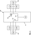
- An aircraft 100 includes a fuselage 102 defining a cabin sized to carry a pilot and one or more passengers.
- the aircraft 100 also includes a first wing 104 and a second wing 106 that each carry one or more propeller arrangements 108 or other propulsion components.
- three propeller arrangements 108 are disposed at each wing 104, 106.
- each wing 104, 106 may carry any desired number or propulsion components.
- each propeller arrangement 108 includes a propeller, a motor, and an inverter to operate the propeller arrangement 108. Other configurations are possible.
- the aircraft 100 includes a power system 110 including at least one battery 112 that powers the propeller arrangements 108 via a power bus 114.
- the propeller arrangements 108 are powered by a main battery 112 carried by the fuselage 102.
- the propeller arrangements 108 may be powered by one or more batteries 112 carried by the wings 104, 106.
- the power system 110 also provides electric power to other components of the aircraft such as the flight management system, the control display unit, and/or lighting.
- the power system 110 also provides electric power to one or more components 116 (e.g., a compressor, a pump, etc.) of a thermal management system 120 used to cool the battery 112 and/or other components such as the propeller arrangement 108.
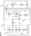
- FIG. 2 illustrates an example thermal management system 120 including one or more cooling circuits 122, 124, 126, 128 that cool various components of the aircraft 100.
- the thermal management system 120 includes a battery cooling circuit 122 configured to cool one or more batteries 112 of the power system 110, a first propeller arrangement cooling circuit 126 configured to cool one or more of the propeller arrangements 108, and a refrigeration circuit 124 configured to cool one or more of the cooling circuits 122, 126.
- a battery cooling circuit 122 configured to cool one or more batteries 112 of the power system 110
- a first propeller arrangement cooling circuit 126 configured to cool one or more of the propeller arrangements 108
- a refrigeration circuit 124 configured to cool one or more of the cooling circuits 122, 126.
- only one propeller arrangement 108 and corresponding cooling circuit 126 is shown. It will be understood however, that the same cooling circuit 126 may service multiple propeller arrangements 108.
- each propeller arrangement 108 may have a respective battery 112 and battery cooling circuit 122.
- the refrigeration circuit 124 includes a conduit 138 through which the refrigerant (e.g., a Hydrofluorocarbon such as R-134a or R410A or other refrigerant) is carried through the refrigeration circuit 124.
- the refrigeration circuit 124 also includes a compressor 140 configured to draw the refrigerant along the conduit 138 and to pressurize (e.g., vaporize) the refrigerant; a condenser arrangement 143 at which heat is removed from the pressurized refrigerant; and an expansion valve 146 at which a pressure drop is created so that low temperature, low pressure refrigerant is then conveyed to the chiller 136.
- the refrigerant e.g., a Hydrofluorocarbon such as R-134a or R410A or other refrigerant
- the refrigeration circuit 124 also includes a compressor 140 configured to draw the refrigerant along the conduit 138 and to pressurize (e.g., vaporize) the refrigerant; a condenser
- the condenser arrangement 143 includes a liquid-cooled condenser 142 at which at least some heat is removed from the pressurized refrigerant; and an air-cooled condenser 144 at which additional heat is removed from the pressurized refrigerant.
- the refrigeration circuit 124 circulates the refrigerant through the liquid-cooled condenser 142 before circulating the refrigerant through the air-cooled condenser 144 (e.g., see FIG. 3 ). In other implementations, however, the refrigerant may be circulated through the air-cooled condenser 144 first.
- the air-cooled condenser 144 is exposed to ambient air outside the aircraft 100 or air routed from outside the aircraft to the air-cooled condenser 144.
- the battery cooling circuit 122 includes a tank 130 configured to hold coolant (e.g., water, propylene glycol, ethylene glycol, or other antifreeze solution), a pump 132 configured to draw the coolant from the tank 130, and a conduit 134 along which the coolant flows through the battery cooling circuit 122.
- coolant e.g., water, propylene glycol, ethylene glycol, or other antifreeze solution
- the conduit 134 is directed from the pump 132 towards the battery 112.
- the coolant After absorbing heat from the battery 112, the coolant is directed to a chiller 136 at which heat is rejected from the coolant to the refrigerant passing through the refrigeration circuit 124.
- the cooled coolant then passes back to the tank 130 (e.g., see FIG. 4 ).
- the propeller arrangement cooling circuit 126 includes a conduit 128 through which coolant flows through the circuit 126.
- the propeller arrangement cooling circuits 126 also includes a tank 148, a pump arrangement 150 of one or more pumps to draw coolant from the tank 148 and circulate the coolant through the conduit 128, and a radiator arrangement 152 exposed to ambient air outside the aircraft.
- the coolant passes from the pump arrangement 150 to a motor and/or an inverter of one or more of the propeller arrangements 108 from which heat is absorbed by the coolant.
- the heated coolant is air cooled at the radiator 152 before returning to the tank 148 (e.g., see FIG. 4 ).
- the radiator arrangement 152 includes one or more radiators.
- a flow control valve 151 directs coolant flow to the one or more of the radiators.
- the flow control valve 151 may control how much coolant flows to each radiator.
- the radiator arrangement 152 includes a radiator for each propeller arrangement 108.
- the radiator arrangement 152 includes three radiators 152a, 152b, 152c.
- the radiator arrangement 152 may includes a greater or lesser number of radiators.
- the radiator arrangement 152 includes all of the radiators disposed on a wing 104, 106 of the aircraft 100.
- the radiator arrangement 152 includes all of the radiators disposed on both wings 104, 106 (e.g., by fluidly combining propeller arrangement cooling circuits 126 of both wings 104, 106).
- the liquid-cooled condenser 142 is cooled by the coolant circulated by the pump 150 of the propeller arrangement cooling circuit 126.
- the propeller arrangement cooling circuit 126 includes a condenser routing path 141 leading past the liquid-cooled condenser 142 of the refrigeration circuit 124. Coolant routed along the condenser routing path 141 cools the vaporized refrigerant within the condenser 142.
- the condenser routing path 141 extends to the liquid-cooled condenser 142 from a location upstream of the propeller arrangement 108 (e.g., see FIG. 4 ).
- a first valve arrangement 109 e.g. a directional control valve
- the first valve arrangement 109 may direct a first portion (e.g., some, all, or none) of the coolant drawn from the tank 148 to the propeller arrangement 108 (e.g., see FIG. 4 ).
- the first valve arrangement 109 also may direct a second portion (e.g., some, all, or none) of the coolant drawn from the tank 148 along the condenser routing path 141 to the liquid-cooled condenser 142 (e.g., see FIGS. 6 and 7 ).
- the first portion is larger than the second portion.
- the first valve arrangement 109 selectively closes the condenser routing path 141 and directs all of the coolant to the propeller arrangement 108 (e.g., see FIG. 4 ).
- the cooled coolant flowing from the radiator arrangement 152 may be further cooled by the refrigeration circuit 124.
- a downstream valve arrangement 154 is disposed downstream of the radiator arrangement 152.
- a first return path 160 extends from the downstream valve arrangement 154 to the tank 148 of the propeller arrangement cooling circuit 126.
- a second return path 162 extends from the downstream valve arrangement 154 to the chiller 136 and then back to the tank 148.
- the downstream valve arrangement 154 is configured to selectively direct the coolant from the radiator arrangement 152 along the first return path 160 and/or along the second return path 162.
- the radiator arrangement 152 is able to provide sufficient cooling to accommodate the heat load from both the propeller arrangement 108 and the liquid-cooled condenser 142. In such cases, the downstream valve arrangement 154 may direct all of the coolant from the radiator 152 back to the tank 148.
- the ambient temperature Tamb is above a threshold T2 (e.g., 25 degrees Celsius, 30 degrees Celsius, 35 degrees Celsius, etc.)
- the downstream valve arrangement 154 may direct all of the coolant from the radiator 152 to pass through the chiller 136.
- the downstream valve arrangement 154 may direct a portion of the coolant from the radiator 152 to the tank 148 and another portion of the coolant to the chiller 136 for additional cooling before being returned to the tank 148.
- some or all of the coolant may be directed to the chiller 136 for cooling regardless of the ambient temperature.
- each of the coolant circuits 122, 126 operates independently.
- the battery cooling circuit 122 has a first coolant that circulates around the battery cooling circuit 122 including along a first path through the chiller 136 while the propeller arrangement cooling circuit 126 has a second coolant that circulates around the propeller arrangement cooling circuit 126 including along a separate, second path through the chiller 136 (e.g., see FIG. 2 ).
- one or more of the coolant circuits 122, 126 may be fluidly coupled together by a return valve 164 (e.g., a directional control valve).
- the coolant circuits 122, 126 may be fluidly coupled during a failure of one or more components of one of the coolant circuits or during a period where one or more components of the power system 110 require extra cooling.
- the first coolant of the battery arrangement cooling circuit 122 is combined with the second coolant of the propeller arrangement cooling circuit 126 prior to passing through the chiller 136 (e.g., see FIG. 8 ). The combined fluid may pass along a common pathway through the chiller 136.
- the combined coolant may be directed to the return valve 164, which directs some of the coolant along a battery circuit return path 164 towards the tank 130 of the battery cooling circuit 122 and other of the coolant along a propeller circuit return path 166 towards the tank 148 of the propeller arrangement cooling circuit 126.
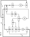
- FIG. 9 illustrates an alternative configuration of the thermal management system 120 in which coolant is routed to the liquid-cooled condenser 142 after being routed past the propeller arrangement 108.
- the coolant absorbs heat from the propeller arrangement 108 and from the liquid-cooled condenser 142 before being routed to the radiator arrangement 152.
- a valve arrangement 145 may be disposed downstream of the propeller arrangement 108 and upstream of the radiator arrangement 152.
- the valve arrangement 145 e.g., a directional control valve
- the heated coolant is routed toward the radiator arrangement 152.
- the thermal management system 120 does not include a valve arrangement 145 and instead directs all heated coolant from the propeller arrangement 108 to the liquid-cooled condenser 142.
- routing the coolant to both the propeller arrangement 108 and the liquid-cooled condenser 142 allows a greater level of fluid flow past these components.
- the coolant directed to both the propeller arrangement 108 and the liquid-cooled condenser 142 is cooled at both he radiator arrangement 152 and the chiller 136 (e.g., see the second return path 162 of FIGS. 7 and 8 ).
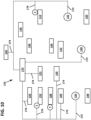
- an electronic controller 170 manages operation of various components of the thermal management system 120.
- the electronic controller 170 includes a memory storing operation instructions and a processor configured to implement the operation instructions.
- the electronic controller 170 manages operation of the pumps 132, 150 of the coolant circuits 122, 126 and the compressor 140 of the refrigeration circuit 124 via control lines 172.
- the electronic controller 170 manages operation of the various valves 109, 151, 154, 164, 145 (e.g., directional control valves, flow control valves, etc.) to direct coolant flow through the thermal management system 120 via control lines 174.
- the electronic controller 170 manages operation of one or more temperature sensors T via control lines 176.
- the temperature sensors T are configured to measure temperatures (or other properties from which temperature may be derived) along the coolant flow paths of the cooling circuits 122, 126, at various power components (e.g., the battery 112, the propeller arrangement 108, etc.), and/or outside the aircraft (e.g., to determine an ambient temperature).
- Representative control lines 172, 174, 176 are shown in FIG. 10 .
- the various powered components of the aircraft 100 draw power generally consistently except during certain high power events (e.g., take-off, landing, hovering, turning, etc.).
- One or more powered components e.g., one or more propeller arrangements 108, the battery 112, etc.
- the electronic controller 170 may monitor temperatures of various components (e.g., the battery 112, the first condenser 142, the propeller arrangement 108, etc.) and may adjust the coolant flow through the thermal management system 120 as needed.
- the electronic controller 170 may connect and disconnect the coolant circuits 122, 126 as needed to provide more or less cooling to select components.
- the electronic controller 170 also may increase or decrease an amount of coolant flow along the battery cooling circuit 122 and/or along the propeller arrangement cooling circuit 126 (e.g., by speeding up or slowing down the pumps 132, 150). Similarly, the electronic controller 170 also may increase or decrease the refrigerant flow along the refrigeration circuit 124 (e.g., by speeding up or slowing down the compressor 132).
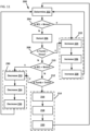
- FIG. 11 is a flow chart illustrating an example process 200 by which the electronic controller 170 manages the thermal management system 120 during a flight.
- the process 200 includes a determine operation 202 at which a battery cooling load BCL for the battery 112 is determined.
- the electronic controller 170 may measure a temperature of the battery 112.
- the process 200 determines whether the cooling load BCL of the battery 112 exceeds a predetermined threshold Bmax that is set based on a maximum temperature for which the battery 112 is rated.
- the threshold Bmax is set at the maximum temperature for which the battery 112 is rated.
- the threshold Bmax is set a few (e.g., 1, 2, 3, 4, or 5) degrees below the maximum temperature for which the battery 112 is rated.
- the process 200 determines whether the ambient temperature Tamb is above a predetermined threshold Tmax.
- the threshold Tmax is set based on a temperature at which the air-cooled condenser 144 provides inadequate cooling to the coolant.
- the threshold Tmax may be 45 degrees Celsius, 50 degrees Celsius, 55 degrees Celsius, 60 degrees Celsius, etc.).
- the threshold Tmax is set based on a temperature at which the radiator 152 provides inadequate cooling to the propeller arrangement 108 during normal operation.
- the threshold Tmax may be 25 degrees Celsius, 30 degrees Celsius, 35 degrees Celsius, etc.).
- the process 200 determines whether the ambient temperature is not too warm at module 208. If the process 200 determines the ambient temperature is not too warm at module 208, then the process 200 proceeds to a third module 210 at which the process 200 determines whether the battery cooling load BCL is below another threshold Tmin that is set based on a minimum temperature for which the battery 112 is rated.
- the threshold Bmin is set at the minimum temperature for which the battery 112 is rated. In another example, the threshold Bmin is set a few (e.g., 1, 2, 3, 4, or 5) degrees above the minimum temperature for which the battery 112 is rated.
- the process 200 determines whether the ambient temperature Tamb is below a predetermined threshold Tmin. In an example, the threshold Tmin is set based on a temperature at which the air-cooled condenser 144 cools the coolant below the Bmin temperature threshold.
- the process 200 determines the battery cooling load BCL is within the thresholds Bmax and Bmin and determines the ambient temperature is within the temperature thresholds Tmax and Tmin, then the process 200 proceeds a set 214 of operations at which the electronic controller 170 operates the coolant circuits 122, 126 and the refrigerant circuit 124 in a normal state.
- the operation set 214 includes a first operation 216 at which a percentage of coolant flow the valve 109 directs to the first condenser 142 is determined and set. In certain examples, the percentage of coolant flow is determined to be zero and the condenser routing path 141 is closed.
- the operation set 214 also includes a second operation 218 at which a speed of the compressor 140 is determined and set to provide sufficient cooling to the coolant of the battery cooling circuit 122.
- the operation set 214 includes a third operation 220 at which a speed of the battery pump 132 is determined and set to provide adequate coolant flow past the battery 112 to sufficiently cool the battery 112 (e.g., to maintain a battery temperature between 20 and 30 degrees Celsius, between 15 and 35 degrees Celsius, between 22 and 28 degrees Celsius, between 10 and 40 degrees Celsius, etc.).
- the process 200 proceeds to a first adjustment set 222 of operations at which the electronic controller 170 modifies operation of the refrigerant circuit 124, the battery cooling circuit 122, and/or the propeller arrangement cooling circuit 126 to increase the level of cooling provided to the battery 112.
- the first adjustment set 222 of operations includes a first increase operation 224 at which the percentage flow of coolant directed to the liquid-cooled condenser 142 is increased.
- the electronic controller 170 may actuate the valve 109 to begin directing coolant flow (or to increase coolant flow) to the liquid-cooled condenser 142.
- the electronic controller 170 may increase a speed of the pump 150 to increase the flow rate past the liquid-cooled condenser 142.
- Increasing the flow of coolant to the liquid-cooled condenser will increase the amount of cooling of the refrigerant at the liquid-cooled condenser 142 and hence enhance the efficiency of the refrigerant circuit 124.
- the liquid-cooled condenser 142 may supplement cooling the refrigerant when a warm ambient temperature Tamb mitigates the amount of cooling provided by the air-cooled condenser 144.
- the first adjust set 222 of operations also may include fluidly connecting the propeller arrangement cooling circuit 126 to the battery cooling circuit 122 to enhance the level of cooling provided to the liquid-cooled condenser 142.
- the electronic controller 170 may actuate the downstream valve arrangement 154 to fluidly couple the first coolant and the second coolant. Accordingly, the coolant cooling the liquid-cooled condenser 142 would be cooled both by the radiator 152 of the propeller arrangement cooling circuit 126 and also by the refrigeration circuit 124 at the chiller 136 of the battery cooling circuit 122.
- the first adjustment set 222 of operations includes a second increase operation 226 at which the flow of refrigerant through the refrigeration circuit 124 is increased.
- the electronic controller 170 may increase a speed of the compressor 140.
- the first adjustment set 222 of operations includes a third increase operation 228 at which a coolant flow through the battery cooling circuit 122 is increased.
- the electronic controller 170 may increase the speed of the battery pump 132. The process 200 returns to the determine operation 202 to check the temperatures again.
- the process 200 proceeds to a second adjustment set 230 of operations at which the electronic controller 170 modifies operation of the refrigerant circuit 124, the battery cooling circuit 122, and/or the propeller arrangement cooling circuit 126 to decrease the level of cooling provided to the battery 112 and/or to the propeller arrangement 108.
- the second adjustment set 230 of operations includes a first decrease operation 232 at which the percentage flow of coolant directed to the liquid-cooled condenser 142 is decreased.
- the electronic controller 170 may actuate the valve 109 to reduce the amount of coolant directed to the liquid-cooled condenser 142.
- the electronic controller 170 may actuate the valve 109 to close the condenser routing path 141 to cease coolant flow to the liquid-cooled condenser 142. In such examples, the refrigerant would rely on air cooling by the condenser 144.
- the second adjustment set 230 of operations includes a second decrease operation 234 at which the flow of refrigerant through the refrigeration circuit 124 is decreased.
- the electronic controller 170 may decrease a speed of the compressor 140.
- the second adjustment set 230 of operations includes a third decrease operation 236 at which a coolant flow through the battery cooling circuit 122 is decreased.
- the electronic controller 170 may decrease the speed of the battery pump 132. The process 200 returns to the determine operation 202 to check the temperatures again.
Landscapes
- Engineering & Computer Science (AREA)
- Chemical & Material Sciences (AREA)
- Mechanical Engineering (AREA)
- General Chemical & Material Sciences (AREA)
- Chemical Kinetics & Catalysis (AREA)
- Electrochemistry (AREA)
- Manufacturing & Machinery (AREA)
- Physics & Mathematics (AREA)
- Thermal Sciences (AREA)
- Aviation & Aerospace Engineering (AREA)
- Combustion & Propulsion (AREA)
- General Engineering & Computer Science (AREA)
- Automation & Control Theory (AREA)
- Cooling, Air Intake And Gas Exhaust, And Fuel Tank Arrangements In Propulsion Units (AREA)
Applications Claiming Priority (1)
| Application Number | Priority Date | Filing Date | Title |
|---|---|---|---|
| IN202111041292 | 2021-09-14 |
Publications (1)
| Publication Number | Publication Date |
|---|---|
| EP4147977A1 true EP4147977A1 (fr) | 2023-03-15 |
Family
ID=83318927
Family Applications (1)
| Application Number | Title | Priority Date | Filing Date |
|---|---|---|---|
| EP22195471.2A Pending EP4147977A1 (fr) | 2021-09-14 | 2022-09-13 | Système de gestion thermique à double condenseur |
Country Status (2)
| Country | Link |
|---|---|
| US (1) | US20230079696A1 (fr) |
| EP (1) | EP4147977A1 (fr) |
Families Citing this family (1)
| Publication number | Priority date | Publication date | Assignee | Title |
|---|---|---|---|---|
| CN116505136B (zh) * | 2023-06-25 | 2024-03-19 | 宁德时代新能源科技股份有限公司 | 热管理控制方法、装置、设备及存储介质 |
Citations (4)
| Publication number | Priority date | Publication date | Assignee | Title |
|---|---|---|---|---|
| DE102008062176A1 (de) * | 2008-12-13 | 2010-06-17 | Modine Manufacturing Co., Racine | Einrichtung und Verfahren zum Temperieren von elektrischen Elementen |
| US20120085512A1 (en) * | 2010-10-07 | 2012-04-12 | Audi Ag | Vehicle cooling system |
| US20190128570A1 (en) * | 2017-11-02 | 2019-05-02 | Rolls-Royce Plc | Thermal management system |
| US20210156296A1 (en) * | 2019-11-25 | 2021-05-27 | Xi'an Jiaotong University | Thermal management system and method for hybrid vehicle |
-
2022
- 2022-09-13 EP EP22195471.2A patent/EP4147977A1/fr active Pending
- 2022-09-14 US US17/944,438 patent/US20230079696A1/en active Pending
Patent Citations (4)
| Publication number | Priority date | Publication date | Assignee | Title |
|---|---|---|---|---|
| DE102008062176A1 (de) * | 2008-12-13 | 2010-06-17 | Modine Manufacturing Co., Racine | Einrichtung und Verfahren zum Temperieren von elektrischen Elementen |
| US20120085512A1 (en) * | 2010-10-07 | 2012-04-12 | Audi Ag | Vehicle cooling system |
| US20190128570A1 (en) * | 2017-11-02 | 2019-05-02 | Rolls-Royce Plc | Thermal management system |
| US20210156296A1 (en) * | 2019-11-25 | 2021-05-27 | Xi'an Jiaotong University | Thermal management system and method for hybrid vehicle |
Also Published As
| Publication number | Publication date |
|---|---|
| US20230079696A1 (en) | 2023-03-16 |
Similar Documents
| Publication | Publication Date | Title |
|---|---|---|
| CN111409411B (zh) | 空气调节和电池冷却装置以及用于运行空气调节和电池冷却装置的方法 | |
| CN111532098B (zh) | 空气调节和电池冷却装置及其运行方法 | |
| US10343484B2 (en) | Electric vehicle thermal management system with series and parallel structure | |
| EP3123085B1 (fr) | Équipement de réfrigération de véhicule possédant un système de rejet de chaleur de liquide | |
| US10098260B2 (en) | Thermal management systems for electronics | |
| US11318813B2 (en) | Thermal system for an electric or hybrid vehicle, electric or hybrid vehicle, method for operating a thermal system | |
| US8448460B2 (en) | Vehicular combination chiller bypass system and method | |
| US8042343B2 (en) | Cooling of avionics using a fuel tank and refrigerant source | |
| US20200276882A1 (en) | Cooling System for a Motor Vehicle and Motor Vehicle Having Such a Cooling System | |
| KR102294593B1 (ko) | 자동차의 열 시스템 및 상기 열 시스템의 작동 방법 | |
| WO2018208208A1 (fr) | Agencement de refroidissement pour le refroidissement d'une machine électrique et d'au moins un autre composant d'une unité d'alimentation électrique et véhicule comprenant un tel agencement de refroidissement | |
| EP3279091B1 (fr) | Système de régulation thermique de l'électronique d'un aéronef | |
| EP4147977A1 (fr) | Système de gestion thermique à double condenseur | |
| KR20230098622A (ko) | 배터리 구동 차량용 냉각기가 있는 히트 펌프 어셈블리 및 히트 펌프 어셈블리 작동 방법 | |
| CN113580871B (zh) | 车辆及其热管理系统 | |
| US11203247B2 (en) | Thermal regulation system provided with Peltier cell for electric drive vehicles | |
| US9698435B2 (en) | System and method for cooling an aircraft fuel cell system | |
| US11888139B2 (en) | Temperature adjustment circuit | |
| US20230070111A1 (en) | Thermal management system | |
| EP4141609A1 (fr) | Système de gestion thermique proactif | |
| US20240076043A1 (en) | Moving object | |
| US20240075787A1 (en) | Cooling system for cooling the battery of an electric vehicle | |
| US20220196300A1 (en) | Two-phase Cooling System | |
| US20240300294A1 (en) | Thermal management system | |
| EP3650266A1 (fr) | Système de régulation thermique pour véhicules à commande électrique et véhicule à commande électrique fourni avec ce système |
Legal Events
| Date | Code | Title | Description |
|---|---|---|---|
| PUAI | Public reference made under article 153(3) epc to a published international application that has entered the european phase |
Free format text: ORIGINAL CODE: 0009012 |
|
| STAA | Information on the status of an ep patent application or granted ep patent |
Free format text: STATUS: THE APPLICATION HAS BEEN PUBLISHED |
|
| AK | Designated contracting states |
Kind code of ref document: A1 Designated state(s): AL AT BE BG CH CY CZ DE DK EE ES FI FR GB GR HR HU IE IS IT LI LT LU LV MC MK MT NL NO PL PT RO RS SE SI SK SM TR |
|
| P01 | Opt-out of the competence of the unified patent court (upc) registered |
Effective date: 20230521 |
|
| STAA | Information on the status of an ep patent application or granted ep patent |
Free format text: STATUS: REQUEST FOR EXAMINATION WAS MADE |
|
| 17P | Request for examination filed |
Effective date: 20230914 |
|
| RBV | Designated contracting states (corrected) |
Designated state(s): AL AT BE BG CH CY CZ DE DK EE ES FI FR GB GR HR HU IE IS IT LI LT LU LV MC MK MT NL NO PL PT RO RS SE SI SK SM TR |