EP4147928A1 - Hydraulic adjustment unit, brake system and control method - Google Patents
Hydraulic adjustment unit, brake system and control method Download PDFInfo
- Publication number
- EP4147928A1 EP4147928A1 EP20935487.7A EP20935487A EP4147928A1 EP 4147928 A1 EP4147928 A1 EP 4147928A1 EP 20935487 A EP20935487 A EP 20935487A EP 4147928 A1 EP4147928 A1 EP 4147928A1
- Authority
- EP
- European Patent Office
- Prior art keywords
- brake
- control valve
- wheel cylinders
- group
- brake pipe
- Prior art date
- Legal status (The legal status is an assumption and is not a legal conclusion. Google has not performed a legal analysis and makes no representation as to the accuracy of the status listed.)
- Withdrawn
Links
- 238000000034 method Methods 0.000 title claims abstract description 132
- 239000012530 fluid Substances 0.000 claims description 257
- 238000004891 communication Methods 0.000 claims description 72
- 230000008569 process Effects 0.000 claims description 61
- 230000002457 bidirectional effect Effects 0.000 claims description 25
- 230000009977 dual effect Effects 0.000 abstract description 19
- 238000010586 diagram Methods 0.000 description 24
- 230000006870 function Effects 0.000 description 24
- 230000033001 locomotion Effects 0.000 description 13
- 238000004590 computer program Methods 0.000 description 7
- 230000007246 mechanism Effects 0.000 description 4
- 230000008878 coupling Effects 0.000 description 3
- 238000010168 coupling process Methods 0.000 description 3
- 238000005859 coupling reaction Methods 0.000 description 3
- 230000000903 blocking effect Effects 0.000 description 2
- 238000006243 chemical reaction Methods 0.000 description 2
- 230000001960 triggered effect Effects 0.000 description 2
- 230000009286 beneficial effect Effects 0.000 description 1
- 230000005540 biological transmission Effects 0.000 description 1
- 230000008859 change Effects 0.000 description 1
- 238000005516 engineering process Methods 0.000 description 1
- 238000002955 isolation Methods 0.000 description 1
- 230000003287 optical effect Effects 0.000 description 1
- 230000004044 response Effects 0.000 description 1
- 238000007789 sealing Methods 0.000 description 1
Images






Classifications
-
- B—PERFORMING OPERATIONS; TRANSPORTING
- B60—VEHICLES IN GENERAL
- B60T—VEHICLE BRAKE CONTROL SYSTEMS OR PARTS THEREOF; BRAKE CONTROL SYSTEMS OR PARTS THEREOF, IN GENERAL; ARRANGEMENT OF BRAKING ELEMENTS ON VEHICLES IN GENERAL; PORTABLE DEVICES FOR PREVENTING UNWANTED MOVEMENT OF VEHICLES; VEHICLE MODIFICATIONS TO FACILITATE COOLING OF BRAKES
- B60T13/00—Transmitting braking action from initiating means to ultimate brake actuator with power assistance or drive; Brake systems incorporating such transmitting means, e.g. air-pressure brake systems
- B60T13/10—Transmitting braking action from initiating means to ultimate brake actuator with power assistance or drive; Brake systems incorporating such transmitting means, e.g. air-pressure brake systems with fluid assistance, drive, or release
- B60T13/66—Electrical control in fluid-pressure brake systems
- B60T13/68—Electrical control in fluid-pressure brake systems by electrically-controlled valves
- B60T13/686—Electrical control in fluid-pressure brake systems by electrically-controlled valves in hydraulic systems or parts thereof
-
- B—PERFORMING OPERATIONS; TRANSPORTING
- B60—VEHICLES IN GENERAL
- B60T—VEHICLE BRAKE CONTROL SYSTEMS OR PARTS THEREOF; BRAKE CONTROL SYSTEMS OR PARTS THEREOF, IN GENERAL; ARRANGEMENT OF BRAKING ELEMENTS ON VEHICLES IN GENERAL; PORTABLE DEVICES FOR PREVENTING UNWANTED MOVEMENT OF VEHICLES; VEHICLE MODIFICATIONS TO FACILITATE COOLING OF BRAKES
- B60T13/00—Transmitting braking action from initiating means to ultimate brake actuator with power assistance or drive; Brake systems incorporating such transmitting means, e.g. air-pressure brake systems
- B60T13/74—Transmitting braking action from initiating means to ultimate brake actuator with power assistance or drive; Brake systems incorporating such transmitting means, e.g. air-pressure brake systems with electrical assistance or drive
- B60T13/745—Transmitting braking action from initiating means to ultimate brake actuator with power assistance or drive; Brake systems incorporating such transmitting means, e.g. air-pressure brake systems with electrical assistance or drive acting on a hydraulic system, e.g. a master cylinder
-
- B—PERFORMING OPERATIONS; TRANSPORTING
- B60—VEHICLES IN GENERAL
- B60T—VEHICLE BRAKE CONTROL SYSTEMS OR PARTS THEREOF; BRAKE CONTROL SYSTEMS OR PARTS THEREOF, IN GENERAL; ARRANGEMENT OF BRAKING ELEMENTS ON VEHICLES IN GENERAL; PORTABLE DEVICES FOR PREVENTING UNWANTED MOVEMENT OF VEHICLES; VEHICLE MODIFICATIONS TO FACILITATE COOLING OF BRAKES
- B60T13/00—Transmitting braking action from initiating means to ultimate brake actuator with power assistance or drive; Brake systems incorporating such transmitting means, e.g. air-pressure brake systems
- B60T13/10—Transmitting braking action from initiating means to ultimate brake actuator with power assistance or drive; Brake systems incorporating such transmitting means, e.g. air-pressure brake systems with fluid assistance, drive, or release
- B60T13/12—Transmitting braking action from initiating means to ultimate brake actuator with power assistance or drive; Brake systems incorporating such transmitting means, e.g. air-pressure brake systems with fluid assistance, drive, or release the fluid being liquid
-
- B—PERFORMING OPERATIONS; TRANSPORTING
- B60—VEHICLES IN GENERAL
- B60T—VEHICLE BRAKE CONTROL SYSTEMS OR PARTS THEREOF; BRAKE CONTROL SYSTEMS OR PARTS THEREOF, IN GENERAL; ARRANGEMENT OF BRAKING ELEMENTS ON VEHICLES IN GENERAL; PORTABLE DEVICES FOR PREVENTING UNWANTED MOVEMENT OF VEHICLES; VEHICLE MODIFICATIONS TO FACILITATE COOLING OF BRAKES
- B60T13/00—Transmitting braking action from initiating means to ultimate brake actuator with power assistance or drive; Brake systems incorporating such transmitting means, e.g. air-pressure brake systems
- B60T13/10—Transmitting braking action from initiating means to ultimate brake actuator with power assistance or drive; Brake systems incorporating such transmitting means, e.g. air-pressure brake systems with fluid assistance, drive, or release
- B60T13/12—Transmitting braking action from initiating means to ultimate brake actuator with power assistance or drive; Brake systems incorporating such transmitting means, e.g. air-pressure brake systems with fluid assistance, drive, or release the fluid being liquid
- B60T13/14—Transmitting braking action from initiating means to ultimate brake actuator with power assistance or drive; Brake systems incorporating such transmitting means, e.g. air-pressure brake systems with fluid assistance, drive, or release the fluid being liquid using accumulators or reservoirs fed by pumps
- B60T13/142—Systems with master cylinder
- B60T13/145—Master cylinder integrated or hydraulically coupled with booster
- B60T13/146—Part of the system directly actuated by booster pressure
-
- B—PERFORMING OPERATIONS; TRANSPORTING
- B60—VEHICLES IN GENERAL
- B60T—VEHICLE BRAKE CONTROL SYSTEMS OR PARTS THEREOF; BRAKE CONTROL SYSTEMS OR PARTS THEREOF, IN GENERAL; ARRANGEMENT OF BRAKING ELEMENTS ON VEHICLES IN GENERAL; PORTABLE DEVICES FOR PREVENTING UNWANTED MOVEMENT OF VEHICLES; VEHICLE MODIFICATIONS TO FACILITATE COOLING OF BRAKES
- B60T13/00—Transmitting braking action from initiating means to ultimate brake actuator with power assistance or drive; Brake systems incorporating such transmitting means, e.g. air-pressure brake systems
- B60T13/10—Transmitting braking action from initiating means to ultimate brake actuator with power assistance or drive; Brake systems incorporating such transmitting means, e.g. air-pressure brake systems with fluid assistance, drive, or release
- B60T13/12—Transmitting braking action from initiating means to ultimate brake actuator with power assistance or drive; Brake systems incorporating such transmitting means, e.g. air-pressure brake systems with fluid assistance, drive, or release the fluid being liquid
- B60T13/16—Transmitting braking action from initiating means to ultimate brake actuator with power assistance or drive; Brake systems incorporating such transmitting means, e.g. air-pressure brake systems with fluid assistance, drive, or release the fluid being liquid using pumps directly, i.e. without interposition of accumulators or reservoirs
- B60T13/168—Arrangements for pressure supply
-
- B—PERFORMING OPERATIONS; TRANSPORTING
- B60—VEHICLES IN GENERAL
- B60T—VEHICLE BRAKE CONTROL SYSTEMS OR PARTS THEREOF; BRAKE CONTROL SYSTEMS OR PARTS THEREOF, IN GENERAL; ARRANGEMENT OF BRAKING ELEMENTS ON VEHICLES IN GENERAL; PORTABLE DEVICES FOR PREVENTING UNWANTED MOVEMENT OF VEHICLES; VEHICLE MODIFICATIONS TO FACILITATE COOLING OF BRAKES
- B60T13/00—Transmitting braking action from initiating means to ultimate brake actuator with power assistance or drive; Brake systems incorporating such transmitting means, e.g. air-pressure brake systems
- B60T13/10—Transmitting braking action from initiating means to ultimate brake actuator with power assistance or drive; Brake systems incorporating such transmitting means, e.g. air-pressure brake systems with fluid assistance, drive, or release
- B60T13/66—Electrical control in fluid-pressure brake systems
- B60T13/662—Electrical control in fluid-pressure brake systems characterised by specified functions of the control system components
-
- B—PERFORMING OPERATIONS; TRANSPORTING
- B60—VEHICLES IN GENERAL
- B60T—VEHICLE BRAKE CONTROL SYSTEMS OR PARTS THEREOF; BRAKE CONTROL SYSTEMS OR PARTS THEREOF, IN GENERAL; ARRANGEMENT OF BRAKING ELEMENTS ON VEHICLES IN GENERAL; PORTABLE DEVICES FOR PREVENTING UNWANTED MOVEMENT OF VEHICLES; VEHICLE MODIFICATIONS TO FACILITATE COOLING OF BRAKES
- B60T17/00—Component parts, details, or accessories of power brake systems not covered by groups B60T8/00, B60T13/00 or B60T15/00, or presenting other characteristic features
- B60T17/04—Arrangements of piping, valves in the piping, e.g. cut-off valves, couplings or air hoses
-
- B—PERFORMING OPERATIONS; TRANSPORTING
- B60—VEHICLES IN GENERAL
- B60T—VEHICLE BRAKE CONTROL SYSTEMS OR PARTS THEREOF; BRAKE CONTROL SYSTEMS OR PARTS THEREOF, IN GENERAL; ARRANGEMENT OF BRAKING ELEMENTS ON VEHICLES IN GENERAL; PORTABLE DEVICES FOR PREVENTING UNWANTED MOVEMENT OF VEHICLES; VEHICLE MODIFICATIONS TO FACILITATE COOLING OF BRAKES
- B60T17/00—Component parts, details, or accessories of power brake systems not covered by groups B60T8/00, B60T13/00 or B60T15/00, or presenting other characteristic features
- B60T17/08—Brake cylinders other than ultimate actuators
-
- B—PERFORMING OPERATIONS; TRANSPORTING
- B60—VEHICLES IN GENERAL
- B60T—VEHICLE BRAKE CONTROL SYSTEMS OR PARTS THEREOF; BRAKE CONTROL SYSTEMS OR PARTS THEREOF, IN GENERAL; ARRANGEMENT OF BRAKING ELEMENTS ON VEHICLES IN GENERAL; PORTABLE DEVICES FOR PREVENTING UNWANTED MOVEMENT OF VEHICLES; VEHICLE MODIFICATIONS TO FACILITATE COOLING OF BRAKES
- B60T7/00—Brake-action initiating means
- B60T7/02—Brake-action initiating means for personal initiation
- B60T7/04—Brake-action initiating means for personal initiation foot actuated
- B60T7/042—Brake-action initiating means for personal initiation foot actuated by electrical means, e.g. using travel or force sensors
-
- B—PERFORMING OPERATIONS; TRANSPORTING
- B60—VEHICLES IN GENERAL
- B60T—VEHICLE BRAKE CONTROL SYSTEMS OR PARTS THEREOF; BRAKE CONTROL SYSTEMS OR PARTS THEREOF, IN GENERAL; ARRANGEMENT OF BRAKING ELEMENTS ON VEHICLES IN GENERAL; PORTABLE DEVICES FOR PREVENTING UNWANTED MOVEMENT OF VEHICLES; VEHICLE MODIFICATIONS TO FACILITATE COOLING OF BRAKES
- B60T7/00—Brake-action initiating means
- B60T7/12—Brake-action initiating means for automatic initiation; for initiation not subject to will of driver or passenger
-
- B—PERFORMING OPERATIONS; TRANSPORTING
- B60—VEHICLES IN GENERAL
- B60T—VEHICLE BRAKE CONTROL SYSTEMS OR PARTS THEREOF; BRAKE CONTROL SYSTEMS OR PARTS THEREOF, IN GENERAL; ARRANGEMENT OF BRAKING ELEMENTS ON VEHICLES IN GENERAL; PORTABLE DEVICES FOR PREVENTING UNWANTED MOVEMENT OF VEHICLES; VEHICLE MODIFICATIONS TO FACILITATE COOLING OF BRAKES
- B60T8/00—Arrangements for adjusting wheel-braking force to meet varying vehicular or ground-surface conditions, e.g. limiting or varying distribution of braking force
- B60T8/32—Arrangements for adjusting wheel-braking force to meet varying vehicular or ground-surface conditions, e.g. limiting or varying distribution of braking force responsive to a speed condition, e.g. acceleration or deceleration
- B60T8/34—Arrangements for adjusting wheel-braking force to meet varying vehicular or ground-surface conditions, e.g. limiting or varying distribution of braking force responsive to a speed condition, e.g. acceleration or deceleration having a fluid pressure regulator responsive to a speed condition
- B60T8/40—Arrangements for adjusting wheel-braking force to meet varying vehicular or ground-surface conditions, e.g. limiting or varying distribution of braking force responsive to a speed condition, e.g. acceleration or deceleration having a fluid pressure regulator responsive to a speed condition comprising an additional fluid circuit including fluid pressurising means for modifying the pressure of the braking fluid, e.g. including wheel driven pumps for detecting a speed condition, or pumps which are controlled by means independent of the braking system
- B60T8/4072—Systems in which a driver input signal is used as a control signal for the additional fluid circuit which is normally used for braking
- B60T8/4081—Systems with stroke simulating devices for driver input
-
- B—PERFORMING OPERATIONS; TRANSPORTING
- B60—VEHICLES IN GENERAL
- B60T—VEHICLE BRAKE CONTROL SYSTEMS OR PARTS THEREOF; BRAKE CONTROL SYSTEMS OR PARTS THEREOF, IN GENERAL; ARRANGEMENT OF BRAKING ELEMENTS ON VEHICLES IN GENERAL; PORTABLE DEVICES FOR PREVENTING UNWANTED MOVEMENT OF VEHICLES; VEHICLE MODIFICATIONS TO FACILITATE COOLING OF BRAKES
- B60T8/00—Arrangements for adjusting wheel-braking force to meet varying vehicular or ground-surface conditions, e.g. limiting or varying distribution of braking force
- B60T8/32—Arrangements for adjusting wheel-braking force to meet varying vehicular or ground-surface conditions, e.g. limiting or varying distribution of braking force responsive to a speed condition, e.g. acceleration or deceleration
- B60T8/88—Arrangements for adjusting wheel-braking force to meet varying vehicular or ground-surface conditions, e.g. limiting or varying distribution of braking force responsive to a speed condition, e.g. acceleration or deceleration with failure responsive means, i.e. means for detecting and indicating faulty operation of the speed responsive control means
- B60T8/92—Arrangements for adjusting wheel-braking force to meet varying vehicular or ground-surface conditions, e.g. limiting or varying distribution of braking force responsive to a speed condition, e.g. acceleration or deceleration with failure responsive means, i.e. means for detecting and indicating faulty operation of the speed responsive control means automatically taking corrective action
- B60T8/94—Arrangements for adjusting wheel-braking force to meet varying vehicular or ground-surface conditions, e.g. limiting or varying distribution of braking force responsive to a speed condition, e.g. acceleration or deceleration with failure responsive means, i.e. means for detecting and indicating faulty operation of the speed responsive control means automatically taking corrective action on a fluid pressure regulator
-
- B—PERFORMING OPERATIONS; TRANSPORTING
- B60—VEHICLES IN GENERAL
- B60T—VEHICLE BRAKE CONTROL SYSTEMS OR PARTS THEREOF; BRAKE CONTROL SYSTEMS OR PARTS THEREOF, IN GENERAL; ARRANGEMENT OF BRAKING ELEMENTS ON VEHICLES IN GENERAL; PORTABLE DEVICES FOR PREVENTING UNWANTED MOVEMENT OF VEHICLES; VEHICLE MODIFICATIONS TO FACILITATE COOLING OF BRAKES
- B60T13/00—Transmitting braking action from initiating means to ultimate brake actuator with power assistance or drive; Brake systems incorporating such transmitting means, e.g. air-pressure brake systems
- B60T13/10—Transmitting braking action from initiating means to ultimate brake actuator with power assistance or drive; Brake systems incorporating such transmitting means, e.g. air-pressure brake systems with fluid assistance, drive, or release
- B60T13/12—Transmitting braking action from initiating means to ultimate brake actuator with power assistance or drive; Brake systems incorporating such transmitting means, e.g. air-pressure brake systems with fluid assistance, drive, or release the fluid being liquid
- B60T13/14—Transmitting braking action from initiating means to ultimate brake actuator with power assistance or drive; Brake systems incorporating such transmitting means, e.g. air-pressure brake systems with fluid assistance, drive, or release the fluid being liquid using accumulators or reservoirs fed by pumps
- B60T13/142—Systems with master cylinder
-
- B—PERFORMING OPERATIONS; TRANSPORTING
- B60—VEHICLES IN GENERAL
- B60T—VEHICLE BRAKE CONTROL SYSTEMS OR PARTS THEREOF; BRAKE CONTROL SYSTEMS OR PARTS THEREOF, IN GENERAL; ARRANGEMENT OF BRAKING ELEMENTS ON VEHICLES IN GENERAL; PORTABLE DEVICES FOR PREVENTING UNWANTED MOVEMENT OF VEHICLES; VEHICLE MODIFICATIONS TO FACILITATE COOLING OF BRAKES
- B60T2270/00—Further aspects of brake control systems not otherwise provided for
- B60T2270/40—Failsafe aspects of brake control systems
- B60T2270/402—Back-up
-
- B—PERFORMING OPERATIONS; TRANSPORTING
- B60—VEHICLES IN GENERAL
- B60T—VEHICLE BRAKE CONTROL SYSTEMS OR PARTS THEREOF; BRAKE CONTROL SYSTEMS OR PARTS THEREOF, IN GENERAL; ARRANGEMENT OF BRAKING ELEMENTS ON VEHICLES IN GENERAL; PORTABLE DEVICES FOR PREVENTING UNWANTED MOVEMENT OF VEHICLES; VEHICLE MODIFICATIONS TO FACILITATE COOLING OF BRAKES
- B60T2270/00—Further aspects of brake control systems not otherwise provided for
- B60T2270/40—Failsafe aspects of brake control systems
- B60T2270/403—Brake circuit failure
Definitions
- This application relates to the field of automobiles, and more specifically, to a hydraulic adjustment unit, a brake system, and a control method.
- a brake system of an automobile is a system that applies specific braking force to wheels of the automobile to perform forced braking on the automobile to some extent.
- the brake system functions to make a driving automobile forcibly decelerate or even stop as required by a driver or a controller, or to make a stopped automobile stably parked under various road conditions (for example, on a ramp), or to make an automobile driven downhill at a stable speed.
- an electro-hydraulic brake (Electro-Hydraulic Brake, EHB) system usually includes a dual circuit brake system and a distributed brake system.
- a hydraulic adjustment apparatus is used to provide a braking force for a first group of brake wheel cylinders through a first brake pipe, and the hydraulic adjustment apparatus is used to provide a braking force for a second group of brake wheel cylinders through a second brake pipe.
- a hydraulic adjustment apparatus with a bidirectional pressurization function is used as the hydraulic adjustment apparatus in the foregoing dual circuit brake system.
- a second hydraulic chamber of the hydraulic adjustment apparatus in a process of forward pressurization of a hydraulic adjustment apparatus with a bidirectional pressurization function, provides a braking force for a first group of vehicles through a first brake pipe provided with a one-way valve, and the second hydraulic chamber provides a braking force for a second group of vehicles through a second brake pipe provided with a one-way valve.
- a first hydraulic chamber of the hydraulic adjustment apparatus provides a braking force for the first group of vehicle through the first brake pipe provided with the one-way valve
- the first hydraulic chamber provides a braking force for the second group of vehicle through the second brake pipe provided with the one-way valve.
- the first brake pipe and the second brake pipe each control a flow direction of brake fluid based on the one-way valve, and cannot control closing or opening of the brake pipe. Consequently, when one of the brake pipes leaks, the brake fluid in the brake system may be lost along the leaked brake pipes, causing the hydraulic adjustment unit to be incapable of pressurizing the brake system, reducing driving safety of the vehicle.
- This application provides a hydraulic adjustment unit, a brake system, and a control method, to individually pressurize any brake pipe in a dual circuit brake pipe, to improve driving safety of a vehicle.
- a hydraulic adjustment unit in a brake system including a hydraulic adjustment apparatus 10.
- the hydraulic adjustment apparatus 10 includes a first hydraulic chamber 16 and a second hydraulic chamber 17.
- the second hydraulic chamber 17 is connected to a first brake pipe 110 in the brake system and a second brake pipe 120 in the brake system.
- the first brake pipe 110 is used to provide a braking force for a first group of brake wheel cylinders 28 and 29 in the brake system.
- the second brake pipe 120 is used to provide a braking force for a second group of brake wheel cylinders 26 and 27 in the brake system.
- the first brake pipe 110 is provided with a first control valve 111. A closed-open status of the first control valve 111 controls a closed-open status of the first brake pipe 110.
- the second brake pipe 120 is provided with a second control valve 121.
- a closed-open status of the second control valve 121 controls a closed-open status of the second brake pipe 120.
- the first hydraulic chamber 16 is connected to the second brake pipe 120 through a third brake pipe 130 in the brake system.
- the first hydraulic chamber 16 provides a braking force for the second group of brake wheel cylinders 26 and 27 through the second brake pipe 120.
- the third brake pipe 130 is in communication with the first brake pipe 110 through the second brake pipe 120.
- the first hydraulic chamber 16 provides a braking force for the first group of brake wheel cylinders 28 and 29 through the first brake pipe 110.
- the second hydraulic chamber 17 provides the braking force for the first group of brake wheel cylinders 28 and 29 through the first brake pipe 110 provided with the first control valve 111, and provides the braking force for the second group of brake wheel cylinders 26 and 27 through the second brake pipe 120 provided with the second control valve 121, thereby helping individually pressurize the first brake pipe 110 and the second brake pipe 120, and avoiding a prior-art case in which the closed-open status of the first brake pipe 110 and that of the second brake pipe 120 cannot be controlled when the braking forces are provided for the first group of brake wheel cylinders 28 and 29 and the second group of brake wheel cylinders 26 and 27 through the first brake pipe 110 and the second brake pipe 120 with one-way valves.
- the second hydraulic chamber 17 may reuse the first brake pipe 110 provided with the first control valve 111 and the second brake pipe 120 provided with the second control valve 121 to determine whether to provide the braking force for the second group of brake wheel cylinders 26 and 27, thereby helping reduce a quantity of control valves in the brake system and reduce costs of the brake system.
- the hydraulic adjustment apparatus 10 is a hydraulic adjustment apparatus with a bidirectional pressurization function.
- the second hydraulic chamber 17 is connected to a first end of the fourth brake pipe 140, a second end of the fourth brake pipe 140 is connected to a first end of the second control valve 121, and an interface between the third brake pipe 130 and the second brake pipe 120 is connected to a second end of the second control valve 121.
- the second hydraulic chamber 17 provides the braking force for the first group of brake wheel cylinders 28 and 29 through the first brake pipe 110 provided with the first control valve 111, and provides the braking force for the second group of brake wheel cylinders 26 and 27 through the second brake pipe 120 provided with the second control valve 121, thereby helping individually pressurize the first brake pipe 110 and the second brake pipe 120.
- a second end of the first control valve 111 is connected to the second end of the second control valve 121 by using a third control valve 141.
- the third control valve 141 controls connection or disconnection between the second end of the second control valve 121 and the second end of the first control valve 111.
- the third control valve 141 is disposed between the second end of the first control valve 111 and the second end of the second control valve 121.
- pressure balance of the brake fluid between the first brake pipe 110 in which the first control valve 111 is located and the second brake pipe 120 in which the second control valve 121 is located helps improve braking safety of the brake system.
- a first one-way valve 122 is disposed between a first interface of the hydraulic adjustment unit and a second interface of the hydraulic adjustment unit.
- the first interface is an interface between the third brake pipe 130 and the second brake pipe 120.
- the second interface is an interface between the third control valve 141 and the second brake pipe 120.
- the first one-way valve 122 allows the brake fluid to flow from the first interface to the second interface, and the first one-way valve 122 prevents the brake fluid from flowing from the second interface to the first interface.
- the first one-way valve 122 is disposed between the first interface and the second interface, to allow the brake fluid to flow from the first interface to the second interface, and the first one-way valve 122 prevents the brake fluid from flowing from the second interface to the first interface, thereby helping improve braking efficiency of the first hydraulic chamber 16.
- the fourth brake pipe 140 is provided with a fourth control valve 142, and closing or opening of the fourth control valve 142 controls closing or opening of the fourth brake pipe 140.
- the fourth brake pipe 140 is provided with the fourth control valve 142, to control the closing or opening of the fourth brake pipe 140 through the closing or opening of the fourth control valve 142. In this way, in a process in which the first hydraulic chamber 16 provides the braking force, the brake fluid is prevented from flowing into the second hydraulic chamber 17 through the fourth brake pipe, thereby helping improve braking efficiency of the first hydraulic chamber 16.
- the third brake pipe 130 is provided with a fifth control valve 131, and the fifth control valve 131 controls closing or opening of the third brake pipe 130.
- the third brake pipe is provided with the fifth control valve 131, so that the first hydraulic chamber 16 can provide individual braking for the first brake pipe 110 and the second brake pipe 120 through closing or opening of the fifth control valve 131, thereby helping improve driving safety of a vehicle.
- the first hydraulic chamber 16 and the second hydraulic chamber 17 are formed by dividing a hydraulic cylinder 11 in the hydraulic adjustment unit by using a piston 12 in the hydraulic adjustment unit.
- An end portion of the first hydraulic chamber 16 is provided with a push rod support portion 14.
- the push rod support portion 14 supports a push rod 13 for driving the piston 12 to move, and the push rod support portion 14 is provided with a first hydraulic adjustment port 14a.
- the first hydraulic adjustment port 14a is connected to a first outlet pipe 190 of the brake system.
- the push rod 13 is provided with a second hydraulic adjustment port 13a.
- the second hydraulic adjustment port 13a is in communication with the first hydraulic chamber 16.
- the first hydraulic adjustment port 14a When the piston 12 is located at an inner stop point of a piston stroke, the first hydraulic adjustment port 14a is in communication with the second hydraulic adjustment port 13a, and brake fluid in the first hydraulic chamber 16 is discharged from the first hydraulic chamber 16 through the first outlet pipe 180. When the piston 12 is located at a position in the piston stroke other than the inner stop point, the first hydraulic adjustment port 14a is not in communication with the second hydraulic adjustment port 13a.
- the outlet pipe of the first hydraulic chamber 16 is arranged on the push rod support portion 14 (corresponding to the first hydraulic adjustment port 14a) and the push rod 13 (corresponding to the second hydraulic adjustment port 13a) in sections, so that when the piston 12 is located at the inner stop point of the piston stroke, the first hydraulic adjustment port 14a is in communication with the second hydraulic adjustment port 13a, and when the piston 12 is located at the position in the piston stroke other than the inner stop point, the first hydraulic adjustment port 14a is not in communication with the second hydraulic adjustment port 13a.
- a state of connection or disconnection between the first hydraulic adjustment port 14a and the second hydraulic adjustment port 13a is controlled by the position of the piston 12 in the piston stroke, thereby avoiding a case of specially configuring a control valve for the first hydraulic chamber 16 in a conventional hydraulic adjustment apparatus to control closing or opening of the outlet pipe of the first hydraulic chamber 16, and helping reduce a quantity of control valves in the hydraulic adjustment unit and reduce costs in the hydraulic adjustment unit.
- the first hydraulic chamber 16 is connected to a first inlet pipe 190, and the first inlet pipe 190 is configured to press brake fluid in the hydraulic adjustment unit into the first hydraulic chamber 16.
- the brake fluid in the first hydraulic chamber 16 is discharged from the first hydraulic chamber 16 through the first hydraulic adjustment port 14a and the second hydraulic adjustment port 13a that are in communication with each other.
- the outlet pipe of the first hydraulic chamber 16 is arranged on the push rod support portion 14 (corresponding to the first hydraulic adjustment port 14a) and the push rod 13 (corresponding to the second hydraulic adjustment port 13a) in sections, so that when the piston 12 is located at the inner stop point of the piston stroke, the first hydraulic adjustment port 14a is in communication with the second hydraulic adjustment port 13a, and the brake fluid in the first hydraulic chamber 16 can be discharged from the first hydraulic chamber 16 through the first hydraulic adjustment port 14a and the second hydraulic adjustment port 13a that are in communication with each other, thereby helping reduce a quantity of control valves in the hydraulic adjustment unit and reduce costs in the hydraulic adjustment unit.
- a circular or semi-circular first flow guide groove 13b is provided along an outer circumference of the push rod 13, and the first flow guide groove 13b is in communication with the second hydraulic adjustment port 13a.
- the circular or semi-circular first flow guide groove 13b is provided on the outer circumference of the push rod 13, the piston 12 is located at the inner stop point when the push rod 13 rotates, and the first hydraulic adjustment port 14a and the second hydraulic adjustment port 13a can be in communication with each other through the first flow guide groove 13b, thereby helping improve performance of the hydraulic adjustment apparatus.
- a circular or semi-circular second flow guide groove 13c is provided along an inner circumference of the push rod support portion 14, and the second flow guide groove 13c is in communication with the first hydraulic adjustment port 14a.
- the circular or semi-circular second flow guide groove 13c is provided on the inner circumference of the push rod support portion 14, the piston 12 is located at the inner stop point when the push rod 13 rotates, and the first hydraulic adjustment port 14a and the second hydraulic adjustment port 13a can be in communication with each other through the second flow guide groove 13c, thereby helping improve performance of the hydraulic adjustment apparatus.
- the second hydraulic adjustment port 13a is disposed obliquely on the push rod 13 and runs through the push rod 13. A distance between a first end of the second hydraulic adjustment port 13a and the piston 12 is shorter than a distance between a second end of the second hydraulic adjustment port 13a and the piston 12.
- the first end is an end through which the second hydraulic adjustment port 13a is in communication with the first hydraulic adjustment port 14a.
- the second end is an end through which the second hydraulic adjustment port 13a is in communication with the first hydraulic chamber 16.
- the distance between the first end of the second hydraulic adjustment port 13a and the piston 12 is set to be shorter than the distance between the second end of the second hydraulic adjustment port 13a and the piston 12, so that the second hydraulic adjustment port 13a and the first hydraulic adjustment port 14a that are in communication with each other can be in communication with the first hydraulic chamber 16.
- the push rod support portion 14 when the piston 12 is located at the inner stop point, the push rod support portion 14 is spaced apart from the second hydraulic adjustment port 13a.
- the push rod support portion 14 when the piston 12 is located at the inner stop point, the push rod support portion 14 is spaced apart from the second hydraulic adjustment port 13a, to prevent the push rod support portion 14 from blocking the second hydraulic adjustment port 13a, thereby helping the brake fluid flow into the second hydraulic adjustment port 13a, and improving depressurization efficiency of the hydraulic adjustment apparatus.
- a brake system including a first group of brake wheel cylinders 28 and 29, a second group of brake wheel cylinders 26 and 27, and the hydraulic adjustment unit according to any possible implementation of the first aspect.
- the hydraulic adjustment unit provides a braking force for the first group of brake wheel cylinders 28 and 29 through the first brake pipe 110, and the hydraulic adjustment unit provides a braking force for the second group of brake wheel cylinders 26 and 27 through the second brake pipe 120.
- the brake system further includes a driving apparatus 15.
- the driving apparatus 15 drives the piston 12 in the hydraulic adjustment apparatus 10 to move along an inner wall of the hydraulic cylinder 11 of the hydraulic adjustment unit.
- the piston 12 divides the hydraulic cylinder 11 into the first hydraulic chamber 16 and the second hydraulic chamber 17.
- an automobile including the hydraulic adjustment unit according to the second aspect or the possible implementation of the second aspect.
- the hydraulic adjustment unit adjusts pressure of brake fluid in a brake pipe in the brake system to control magnitude of a braking force applied to a brake wheel cylinder in the brake system.
- a method for controlling a brake system includes a hydraulic adjustment apparatus 10 with a bidirectional pressurization function.
- a hydraulic cylinder 11 of the hydraulic adjustment apparatus 10 is divided into a first hydraulic chamber 16 and a second hydraulic chamber 17 by a piston 12.
- the second hydraulic chamber 17 is connected to a first brake pipe 110 in the brake system and a second brake pipe 120 in the brake system.
- the first brake pipe 110 is configured to provide a braking force for a first group of brake wheel cylinders 28 and 29 in the brake system.
- the second brake pipe 120 is configured to provide a braking force for a second group of brake wheel cylinders 26 and 27 in the brake system.
- the first brake pipe 110 is provided with a first control valve 111.
- a closed-open status of the first control valve 111 controls a closed-open status of the first brake pipe 110.
- the second brake pipe 120 is provided with a second control valve 121.
- a closed-open status of the second control valve 121 controls a closed-open status of the second brake pipe 120.
- the first hydraulic chamber 16 is connected to the second brake pipe 120 through a third brake pipe 130 in the brake system.
- the first hydraulic chamber 16 provides a braking force for the second group of brake wheel cylinders 26 and 27 through the second brake pipe 120.
- the third brake pipe 130 is in communication with the first brake pipe 110 through the second brake pipe 120.
- the first hydraulic chamber 16 provides a braking force for the first group of brake wheel cylinders 28 and 29 through the first brake pipe 110.
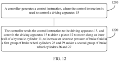
- the method includes: A controller generates a control instruction.
- the control instruction is used to control a driving apparatus 15.
- the controller sends the control instruction to the driving apparatus 15, and controls the driving apparatus 15 to drive the piston 12 to move along an inner wall of the hydraulic cylinder 11, to increase or decrease pressure of brake fluid in the first group of brake wheel cylinders 28 and 29 and/or the second group of brake wheel cylinders 26 and 27.
- the second hydraulic chamber 17 provides the braking force for the first group of brake wheel cylinders 28 and 29 through the first brake pipe 110 provided with the first control valve 111, and provides the braking force for the second group of brake wheel cylinders 26 and 27 through the second brake pipe 120 provided with the second control valve 121, thereby helping individually pressurize the first brake pipe 110 and the second brake pipe 120, and avoiding a prior-art case in which the closed-open status of the first brake pipe 110 and that of the second brake pipe 120 cannot be controlled when the braking forces are provided for the first group of brake wheel cylinders 28 and 29 and the second group of brake wheel cylinders 26 and 27 through the first brake pipe 110 and the second brake pipe 120 with one-way valves.
- the second hydraulic chamber 17 may reuse the first brake pipe 110 provided with the first control valve 111 and the second brake pipe 120 provided with the second control valve 121 to determine whether to provide the braking force for the second group of brake wheel cylinders 26 and 27, thereby helping reduce a quantity of control valves in the brake system and reduce costs of the brake system.
- the method further includes: When a braking circuit for providing the braking force for the first group of brake wheel cylinders 28 and 29 fails, and the first hydraulic chamber 16 is required to provide the braking force for the second group of brake wheel cylinders 26 and 27, the controller controls both the first control valve 111 and the second control valve 121 to be in an open state.
- the first control valve 111 and the second control valve 121 may be open, and the braking force is provided by the first hydraulic chamber 16 for the second group of brake wheel cylinders 26 and 27, thereby helping improve pressurization efficiency of the brake system, and avoiding pressure leakage of the brake fluid caused by the brake fluid flowing into the failed braking circuit.
- the brake system further includes a fourth brake pipe 140.
- the second hydraulic chamber 17 is connected to a first end of the fourth brake pipe 140.
- a second end of the fourth brake pipe 140 is connected to a first end of the second control valve 121.
- the fourth brake pipe 140 is provided with a fourth control valve 142 to control closing or opening of the fourth brake pipe 140.
- the method further includes: When a braking circuit for providing the braking force for the first group of brake wheel cylinders 28 and 29 fails, and the first hydraulic chamber 16 is required to provide the braking force for the second group of brake wheel cylinders 26 and 27, the controller controls both the first control valve 111 and the second control valve 121 to be in an open state and the fourth control valve 142 to be in the open state.
- the first control valve 111, the second control valve 121, and the fourth control valve 142 may be open, and the braking force is provided by the first hydraulic chamber 16 for the second group of brake wheel cylinders 26 and 27, thereby helping improve pressurization efficiency of the brake system, and avoiding pressure leakage of the brake fluid caused by the brake fluid flowing into the failed braking circuit.
- the third brake pipe 130 is provided with a fifth control valve 131, and the fifth control valve 131 controls closing or opening of the third brake pipe 130.
- the method further includes: When a braking circuit for providing the braking force for the first group of brake wheel cylinders 28 and 29 fails, and the first hydraulic chamber 16 is required to provide the braking force for the second group of brake wheel cylinders 26 and 27, the controller controls both the first control valve 111 and the second control valve 121 to be in an open state and the fifth control valve 131 to be in a closed state.
- the first control valve 111 and the second control valve 121 may be open, the fifth control valve 131 is controlled to be closed, and the braking force is provided by the first hydraulic chamber 16 for the second group of brake wheel cylinders 26 and 27, thereby helping improve pressurization efficiency of the brake system, and avoiding pressure leakage of the brake fluid caused by the brake fluid flowing into the failed braking circuit.
- that the controller sends the control instruction to the driving apparatus 15, and controls the driving apparatus 15 to drive the piston 12 to move along an inner wall of the hydraulic cylinder 11, to increase or decrease pressure of brake fluid in the first group of brake wheel cylinders 28 and 29 and/or the second group of brake wheel cylinders 26 and 27 includes: In a process of providing the braking force for the second group of brake wheel cylinders 26 and 27, the controller sends the control instruction to the driving apparatus 15, and controls the driving apparatus 15 to drive the piston 12 to compress a volume of the first hydraulic chamber 16, to press the brake fluid in the first hydraulic chamber 16 into the second group of brake wheel cylinders 26 and 27 through the second brake pipe 120, to increase the pressure of the brake fluid in the second group of brake wheel cylinders 26 and 27.
- the controller controls the piston 12 to compress the volume of the first hydraulic chamber 16 to pressurize the second group of brake wheel cylinders 26 and 27 through the brake fluid in the first hydraulic chamber 16, that is, pressurization is performed on the second group of brake wheel cylinders 26 and 27 individually to improve safety of the brake system.
- the method further includes: When a braking circuit for providing the braking force for the first group of brake wheel cylinders 28 and 29 fails, and the second hydraulic chamber 17 is required to provide the braking force for the second group of brake wheel cylinders 26 and 27, the controller controls the first control valve 111 to be in an open state and controls the second control valve 121 to be in a closed state.
- the first control valve 111 may be open, the second control valve 121 may be closed, and the braking force is provided by the second hydraulic chamber 17 for the second group of brake wheel cylinders 26 and 27, thereby helping improve pressurization efficiency of the brake system, and avoiding pressure leakage of the brake fluid caused by the brake fluid flowing into the failed braking circuit.
- the brake system further includes a fourth brake pipe 140.
- the second hydraulic chamber 17 is connected to a first end of the fourth brake pipe 140.
- a second end of the fourth brake pipe 140 is connected to a first end of the second control valve 121.
- the fourth brake pipe 140 is provided with a fourth control valve 142 to control closing or opening of the fourth brake pipe 140.
- the method further includes: When a braking circuit for providing the braking force for the first group of brake wheel cylinders 28 and 29 fails, and the second hydraulic chamber 17 is required to provide the braking force for the second group of brake wheel cylinders 26 and 27, the controller controls the first control valve 111 to be in an open state and controls the second control valve 121 and the fourth control valve 142 to be in a closed state.
- the first control valve 111 may be open, the second control valve 121 and the fourth control valve 142 may be closed, and the braking force is provided by the second hydraulic chamber 17 for the second group of brake wheel cylinders 26 and 27, thereby helping improve pressurization efficiency of the brake system, and avoiding pressure leakage of the brake fluid caused by the brake fluid flowing into the failed braking circuit.
- the third brake pipe 130 is provided with a fifth control valve 131, and the fifth control valve 131 controls closing or opening of the third brake pipe 130.
- the method further includes: When a braking circuit for providing the braking force for the first group of brake wheel cylinders 28 and 29 fails, and the first hydraulic chamber 16 is required to provide the braking force for the second group of brake wheel cylinders 26 and 27, the controller controls the second control valve 121 to be in an open state and controls the first control valve 111 and the fifth control valve 131 to be in the open state.
- the first control valve 111 and the fifth control valve 131 may be open, the second control valve 121 may be closed, and the braking force is provided by the second hydraulic chamber 17 for the second group of brake wheel cylinders 26 and 27, thereby helping improve pressurization efficiency of the brake system, and avoiding pressure leakage of the brake fluid caused by the brake fluid flowing into the failed braking circuit.
- that the controller sends the control instruction to the driving apparatus 15, and controls the driving apparatus 15 to drive the piston 12 to move along an inner wall of the hydraulic cylinder 11, to increase or decrease pressure of brake fluid in the first group of brake wheel cylinders 28 and 29 and/or the second group of brake wheel cylinders 26 and 27 includes: In a process of providing the braking force for the second group of brake wheel cylinders 26 and 27, the controller sends the control instruction to the driving apparatus 15, and controls the driving apparatus 15 to drive the piston 12 to compress a volume of the second hydraulic chamber 17, to press the brake fluid in the second hydraulic chamber 17 into the second group of brake wheel cylinders 26 and 27 through the second brake pipe 120, to increase the pressure of the brake fluid in the second group of brake wheel cylinders 26 and 27.
- the controller controls the piston 12 to compress the volume of the second hydraulic chamber 17 to pressurize the second group of brake wheel cylinders 26 and 27 through the brake fluid in the second hydraulic chamber 17, that is, pressurization is performed on the second group of brake wheel cylinders 26 and 27 individually to improve safety of the brake system.
- the method further includes: When a braking circuit for providing the braking force for the second group of brake wheel cylinders 26 and 27 fails, and the second hydraulic chamber 17 is required to provide the braking force for the first group of brake wheel cylinders 28 and 29, the controller controls the first control valve 111 to be in an open state and controls the second control valve 121 to be in a closed state.
- the first control valve 111 may be open, the second control valve 121 may be closed, and the braking force is provided by the second hydraulic chamber 17 for the second group of brake wheel cylinders 26 and 27, thereby helping improve pressurization efficiency of the brake system, and avoiding pressure leakage of the brake fluid caused by the brake fluid flowing into the failed braking circuit.
- the brake system further includes a fourth brake pipe 140.
- the second hydraulic chamber 17 is connected to a first end of the fourth brake pipe 140.
- a second end of the fourth brake pipe 140 is connected to a first end of the second control valve 121.
- the fourth brake pipe 140 is provided with a fourth control valve 142 to control closing or opening of the fourth brake pipe 140.
- the method further includes: When a braking circuit for providing the braking force for the second group of brake wheel cylinders 26 and 27 fails, and the second hydraulic chamber 17 is required to provide the braking force for the first group of brake wheel cylinders 28 and 29, the controller controls the second control valve 121 to be in an open state and controls the first control valve 111 and the fourth control valve 142 to be in a closed state.
- the second control valve 121 may be open, the first control valve 111 and the fourth control valve 142 may be closed, and the braking force is provided by the second hydraulic chamber 17 for the second group of brake wheel cylinders 26 and 27, thereby helping improve pressurization efficiency of the brake system, and avoiding pressure leakage of the brake fluid caused by the brake fluid flowing into the failed braking circuit.
- the third brake pipe 130 is provided with a fifth control valve 131, and the fifth control valve 131 controls closing or opening of the third brake pipe 130.
- the method further includes: When a braking circuit for providing the braking force for the first group of brake wheel cylinders 28 and 29 fails, and the second hydraulic chamber 17 is required to provide the braking force for the second group of brake wheel cylinders 26 and 27, the controller controls both the first control valve 111 and the fifth control valve 131 to be in a closed state and the second control valve 121 to be in an open state.
- the second control valve 121 may be open, the first control valve 111 and the fifth control valve 131 may be closed, and the braking force is provided by the second hydraulic chamber 17 for the second group of brake wheel cylinders 26 and 27, thereby helping improve pressurization efficiency of the brake system, and avoiding pressure leakage of the brake fluid caused by the brake fluid flowing into the failed braking circuit.
- that the controller sends the control instruction to the driving apparatus 15, and controls the driving apparatus 15 to drive the piston 12 to move along an inner wall of the hydraulic cylinder 11, to increase or decrease pressure of brake fluid in the first group of brake wheel cylinders 28 and 29 and/or the second group of brake wheel cylinders 26 and 27 includes: In a process of providing the braking force for the first group of brake wheel cylinders 28 and 29, the controller sends the control instruction to the driving apparatus 15, and controls the driving apparatus 15 to drive the piston 12 to compress a volume of the second hydraulic chamber 17, to press the brake fluid in the second hydraulic chamber 17 into the first group of brake wheel cylinders 28 and 29 through the first brake pipe 110, to increase the pressure of the brake fluid in the first group of brake wheel cylinders 28 and 29.
- the controller controls the piston 12 to compress the volume of the second hydraulic chamber 17 to pressurize the first group of brake wheel cylinders 28 and 29 through the brake fluid in the second hydraulic chamber 17, that is, pressurization is performed on the first group of brake wheel cylinders 28 and 29 individually to improve safety of the brake system.
- a control apparatus includes a processing unit and a storage unit.
- the storage unit is configured to store instructions.
- the processing unit executes the instructions stored in the storage unit, so that the control apparatus performs any possible method in the third aspect.
- control apparatus may be an independent controller in an automobile, or may be a chip with a control function in the automobile.
- the processing unit may be a processor.
- the storage unit may be a memory.
- the memory may be a storage unit (for example, a register or a cache) in a chip, or may be a storage unit (for example, a read-only memory or a random access memory), located outside the chip, in the automobile.
- the memory is coupled to the processor. That the memory is coupled to the processor may be understood as that the memory is located inside the processor, or the memory is located outside the processor, to be independent of the processor.
- a computer program product includes computer program code.
- the computer program code When the computer program code is run on a computer, the computer is enabled to perform the methods in the foregoing aspects.
- the computer program code may be stored in a first storage medium.
- the first storage medium may be encapsulated together with the processor, or may be encapsulated separately with the processor. This is not specifically limited in this embodiment of this application.
- a computer-readable medium stores computer program code.
- the computer program code When the computer program code is run on a computer, the computer is enabled to perform the methods in the foregoing aspects.
- an "outlet pipe” and an “inlet pipe” mentioned in the following may correspond to different brake pipes, or may correspond to a same brake pipe.
- the "outlet pipe” and the “inlet pipe” are distinguished only based on functions of the brake pipes in a brake system.
- the first brake pipe in the brake system is used to deliver brake fluid in a brake wheel cylinder to a fluid storage apparatus in a process of depressurizing wheels of an automobile.
- the first brake pipe may be referred to as an "outlet pipe”.
- the first brake pipe In a process of pressurizing the wheels of the automobile, the first brake pipe is used to provide brake fluid for the wheels of the automobile, and provide a braking force for the wheels of the automobile.
- the first brake pipe may be referred to as an "inlet pipe”.
- an "inlet valve”, an “outlet valve”, and a “pressure equalizing valve” used in the following are distinguished only based on functions of the control valves in the brake system.
- a control valve used to control opening or closing of the inlet pipe may be referred to as an "inlet valve” or a “booster valve”.
- a control valve configured to control opening or closing of a fluid return pipe may be referred to as an "outlet valve” or a “pressure reducing valve”.
- a control valve used to isolate a two-stage braking subsystem may be referred to as an "isolation valve".
- the control valve may be a valve commonly used in an existing brake system, for example, a solenoid valve. This is not specifically limited in the embodiments of this application.
- a connection port between the control valve and the brake pipe may be indicated by a first end and a second end, and a flow direction of the brake fluid between the first end and the second end is not limited in this application.
- the brake fluid may flow from the first end of the control valve to the second end of the control valve when the control valve is in a closed state, or the brake fluid may flow from the second end of the control valve to the first end of the control valve when the control valve is in an open state.
- first brake pipe 110 a "second brake pipe 120"
- third brake pipe 130 a "fourth brake pipe 140”
- other brake pipes used in the following may be construed as one or more sections of brake pipes that implement a particular function.
- the third brake pipe 130 is a multi-section brake pipe used to connect a brake master cylinder 3 and a brake wheel cylinder 151 of a first group of wheels.
- FIG. 1 is a schematic diagram of a hydraulic adjustment apparatus according to an embodiment of this application.
- the hydraulic adjustment apparatus 10 shown in FIG. 1 includes a hydraulic cylinder 11, a piston 12, a push rod 13, and a push rod support portion 14.
- the piston 12 moves along an inner wall of the hydraulic cylinder 11.
- the piston 12 divides the hydraulic cylinder 11 into a first hydraulic chamber 16 and a second hydraulic chamber 17.
- An end portion of the first hydraulic chamber 16 is provided with the push rod support portion 14.
- the push rod support portion 14 supports the push rod 13, and the push rod support portion 14 is provided with a first hydraulic adjustment port 14a.
- the push rod 13 is provided with a second hydraulic adjustment port 13a.
- a first end of the second hydraulic adjustment port 13a is in communication with the first hydraulic chamber 16.
- the first hydraulic adjustment port 14a is in communication with a second end of the second hydraulic adjustment port 13a.
- the first hydraulic adjustment port 14a is not in communication with the second end of the second hydraulic adjustment port 13a.
- the driving apparatus 15 pushes, through the push rod 13, the piston 12 to move along the inner wall of the hydraulic cylinder 11 and form the piston stroke, the hydraulic cylinder 11 is divided by the piston 12 into two hydraulic chambers: the first hydraulic chamber 16 and the second hydraulic chamber 17.
- a first flow channel connected to the first hydraulic chamber 16 includes a port 11a and a port 11d.
- a second flow channel connected to the second hydraulic chamber 17 includes a port 11c and a port 11b.
- the piston 12 is movably disposed in the hydraulic cylinder 11, one end of the push rod 13 extends into the hydraulic cylinder 11 and is connected to the piston 12, and the other end of the push rod 13 penetrates the hydraulic cylinder 11 and is in transmission connection with the driving apparatus 15. Driven by the driving apparatus 15, the piston 12 is capable of reciprocating movement within the hydraulic cylinder 11 to implement a pressurization or depressurization (depressurization) operation on the brake system.
- the piston 12 may be driven by the driving apparatus 15, and the driving apparatus 15 may be another apparatus having a driving capability, for example, a motor.
- a driving capability for example, a motor.
- the power conversion mechanism may include, for example, a turbine worm assembly or a ball screw nut assembly.
- a position at which the piston 12 is farthest away from a drive shaft (for example, a crankshaft center) of the driving apparatus 15 is referred to as an "outer stop center”.
- a position at which the piston 12 is closest to the drive shaft (for example, the crankshaft center) of the driving apparatus 15 is referred to as an “inner stop point”.
- a distance between the "outer stop point” and the “inner stop point” is referred to as the piston stroke.
- the first hydraulic chamber 16 and the second hydraulic chamber 17 are separated by the piston 12 and are configured so that volumes of the first hydraulic chamber 16 and the second hydraulic chamber 17 change with movement of the piston 12. Specifically, when the piston 12 moves forward (leftward in FIG. 1 ), the volume of the first hydraulic chamber 16 is increased and the volume of the second hydraulic chamber 17 is reduced. When the piston 12 moves backward (rightward in FIG. 1 ), the volume of the first hydraulic chamber 16 is reduced and the volume of the second hydraulic chamber 17 is increased.
- forward movement of the piston 12 may be referred to as “forward movement” and the backward movement of the piston 12 may be referred to as “reverse movement”.
- forward movement When the hydraulic adjustment apparatus 10 performs a pressurization operation on the brake system, pressurization of the forward movement may be referred to as forward pressurization and pressurization of the reverse movement may be referred to as reverse pressurization.
- reverse pressurization When the hydraulic adjustment apparatus 10 performs a pressurization operation on the brake system, pressurization of the forward movement may be referred to as forward pressurization and pressurization of the reverse movement may be referred to as reverse pressurization.
- the forward pressurization and the reverse pressurization are to be further described below when the hydraulic adjustment unit or the brake system including the hydraulic adjustment apparatus 10 is described.
- the end portion of the first hydraulic chamber 16 is provided with the push rod support portion 14.
- the push rod support portion 14 supports the push rod 13, and the push rod support portion 14 is provided with the first hydraulic adjustment port 14a.
- the push rod support portion 14 and the hydraulic cylinder 11 may be integrally formed, or the push rod support portion 14 and the hydraulic cylinder 11 may be assembled at a later stage. This is not limited in this embodiment of this application.
- the push rod support portion 14 is further provided with a sealing member (not shown), to prevent the brake fluid from flowing out of the first hydraulic chamber 16 through a gap between the push rod 13 and the push rod support portion 14.
- the push rod 13 is provided with the second hydraulic adjustment port 13a.
- the first hydraulic chamber 16 is in communication with the second hydraulic adjustment port 14a through the first hydraulic adjustment port 14a when the piston 12 is located at the inner stop point of the piston stroke. Conversely, when the piston 12 is located at a position in the piston stroke other than the inner stop point, the first hydraulic adjustment port 14a is not in communication with the second hydraulic adjustment port 13a.
- first hydraulic chamber 16 is in communication with the second hydraulic adjustment port 14a through the first hydraulic adjustment port 14a
- the brake fluid in the first hydraulic chamber 16 can be discharged from the first hydraulic chamber 16 through the first hydraulic adjustment port 14a and the second hydraulic adjustment port 13a that are in communication with each other.
- the brake fluid can enter the first hydraulic chamber 16 through the first hydraulic adjustment port 14a and the second hydraulic adjustment port 13a that are in communication with each other.
- the first hydraulic adjustment port 14a and the second hydraulic adjustment port 13a may be considered as the ports of the foregoing first flow channel in communication with the first hydraulic chamber 16.
- the brake fluid in the first hydraulic chamber 16 may flow into the first hydraulic chamber through the third hydraulic adjustment port 11a provided in the first hydraulic chamber.
- the third hydraulic adjustment port 11a is in communication with the first hydraulic chamber 16 and a brake pipe of the brake system.
- the brake pipe may be in communication with a brake wheel cylinder of the automobile wheel, and a controller of the brake system can adjust a braking force applied to the wheel by adjusting hydraulic pressure in the brake pipe.
- the first hydraulic chamber 16 can pump the brake fluid into the brake pipe through the third hydraulic adjustment port 11a, thereby increasing the braking force applied to the wheel.
- the brake fluid in the brake pipe may flow into the first hydraulic chamber 16 through the third hydraulic adjustment port 11a, thereby reducing or canceling the braking force applied to the wheel.
- the hydraulic cylinder 11 may be further provided with a fourth hydraulic adjustment port 11b, and the fourth hydraulic adjustment port 1 1b is configured to communicate the second hydraulic chamber 17 with the brake pipe of the brake system through a pipe.
- the second hydraulic chamber 17 can discharge the brake fluid into the brake pipe through the fourth hydraulic adjustment port 11b, and perform a pressurization operation on the brake pipe, thereby increasing the braking force applied to the wheel.
- the brake fluid in the brake pipe can also be discharged into the second hydraulic chamber 17 through the fourth hydraulic adjustment port 11b to perform a depressurization operation on the brake pipe, thereby reducing or canceling the braking force applied to the wheel.
- the fourth hydraulic adjustment port 11b may also communicate with the second hydraulic chamber 17 and the first hydraulic chamber 16 through the brake pipe.
- the hydraulic cylinder 11 may be further provided with a fifth hydraulic adjustment port 11c, and the fifth hydraulic adjustment port 11c is configured to discharge the brake fluid supplemented by the fluid storage apparatus 30.
- the fifth hydraulic adjustment port 11c is in communication with the fluid storage apparatus 30 through a pipe.
- the brake fluid in the fluid storage apparatus 30 can be replenished into the second hydraulic chamber 17 in time through the fifth hydraulic adjustment port 11c.
- the hydraulic adjustment apparatus 10 provided in this embodiment of this application can implement bidirectional pressurization through forward movement or backward movement, thereby ensuring continuity of the pressurization process, and improving comfort during braking.
- the hydraulic adjustment apparatus 10 in this embodiment of this application can rapidly generate pressure, to rapidly pressurize the brake system, thereby reducing a control response time of the system, and meeting a control and safety requirement of a vehicle.
- the second hydraulic adjustment port 13a may be obliquely provided on the push rod 13 and run through the push rod 13. A distance between a fluid inlet of the second hydraulic adjustment port 13a and the piston 12 is shorter than a distance between a fluid outlet of the second hydraulic adjustment port 13a and the piston 12.
- That the distance between the fluid inlet (also referred to as the first end) of the second hydraulic adjustment port 13a and the piston 12 is shorter than the distance between the fluid outlet (also referred to as the second end) of the second hydraulic adjustment port 13a and the piston 12 may be understood as follows: A side of the second hydraulic adjustment port 13a in communication with the first hydraulic adjustment port 14a is closer to the piston 12 than a side of the second hydraulic adjustment port 13a in communication with the first hydraulic chamber 16.
- the second hydraulic adjustment port 13a may alternatively be a U-shaped hole or the like. This is not limited in this application.
- the push rod support portion 14 may be spaced apart from the second hydraulic adjustment port 13a, or when the piston 12 is located at the inner stop point or the outer stop point, there may be a particular spacing between the push rod support portion 14 and the second hydraulic adjustment port 13a so that the brake fluid in the first hydraulic chamber 16 can enter or exit the second hydraulic adjustment port 13a without being blocked.
- the push rod support portion 14 may alternatively block a part of the second hydraulic adjustment port 13a. This is not limited in this embodiment of this application.
- the push rod 13 may rotate after a long time of operation, and correspondingly, the second hydraulic adjustment port 13a provided on the push rod 13 may also rotate.
- the second hydraulic adjustment port 13a after rotation cannot be in communication with the first hydraulic adjustment port 14a.
- the outlet of the second hydraulic adjustment port 13a after rotation may be blocked by an inner wall of the push rod support portion 14, and correspondingly, the first hydraulic adjustment port 14a may be blocked by an outer wall of the push rod 13.
- a first flow guide groove 13b may be disposed along an outer circumference of the push rod 13, and the first flow guide groove 13b is in communication with the second hydraulic adjustment port 13a. After the push rod 13 rotates, the first flow guide groove 13b can ensure that the second hydraulic adjustment port 13a and the first hydraulic adjustment port 14a remain in communication with each other.
- the first flow guide groove 13b may be in a circular shape or a semi-circular shape along the outer circumference of the push rod 13. Certainly, it is beneficial to reduce impact of the first flow guide groove 13b on mechanical strength of the push rod 13 when the first flow guide groove 13b is a semi-circular groove provided along the outer circumference of the push rod 13. It should be understood that an arc length of the semi-circular ring may be determined based on a maximum amount of rotation of the push rod 13.
- FIG. 2(a) and FIG. 2(b) are a schematic structural diagram of the first flow guide groove according to this embodiment of this application.
- FIG. 2(b) is a main view of the push rod 13
- FIG. 2(a) is a cross-sectional view from a perspective along A-A in FIG. 2(b) .
- the first flow guide groove 13b may be provided along the outer circumference of the push rod 13.
- the first flow guide groove 13b is arranged along the circumference of the push rod 13, and the second hydraulic adjustment port 13a is in communication with the first flow guide groove 13b. In this way, when the piston 12 is moved to the inner stop point, the second hydraulic adjustment port 13a is in communication with the first hydraulic adjustment port 14a through the first flow guide groove 13b, so that press can be reduced rapidly.
- the first flow guide groove 13b is provided along the outer circumference of the push rod 13 and has a particular length, so that when the push rod 13 rotates, the first flow guide groove 13b is always in communication with the first hydraulic adjustment port 14a, and the second hydraulic adjustment port 13a is also in communication with the first flow guide groove 13b, that is, in this case, it can still be ensured that the second hydraulic adjustment port 13a and the first hydraulic adjustment port 14a are in communication with each other.
- the first flow guide groove 13b is an annular end-to-end groove. This ensures that the first flow guide groove 13b and the first hydraulic adjustment port 14a always remain in communication with each other, and that the first flow guide groove 13b and the second hydraulic adjustment port 13a also always remain in communication with each other, regardless of an angle of rotation by the push rod 13. In this way, the second hydraulic adjustment port 13a and the first hydraulic adjustment port 14a always remain in communication with each other.
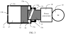
- a circular or semi-circular second flow guide groove 13c is provided along an inner circumference of the push rod support portion 14, and the second flow guide groove 13c is in communication with the first hydraulic adjustment port 14a.
- the following describes a structure of the second flow guide groove 13c in this embodiment of this application with reference to FIG. 3 .
- FIG. 3 is a schematic structural diagram of the second flow guide groove according to this embodiment of this application.
- the second flow guide groove 13c may be provided on the inner wall of the push rod support portion 14, and the second flow guide groove 13b is in communication with the first hydraulic adjustment port 14a.
- the second flow guide groove 13c may be provided along the inner circumference of the push rod support portion 14. Because the inner circumference of the push rod support portion 14 always covers the outer circumference of the push rod 13, even if the push rod 13 rotates, the second flow guide groove 13c located on the inner circumference of the push rod support portion 14 can also be in communication with the second hydraulic adjustment port 13a, that is, the second hydraulic adjustment port 13a is in communication with the first hydraulic adjustment port 14a.
- the second flow guide groove 13c is provided on the push rod support portion 14, thereby helping reduce impact on mechanical strength of the push rod 13, and preventing the push rod 13 from breaking after a long time of working.
- a first hydraulic chamber in the hydraulic adjustment apparatus provides a braking force for a first group of wheels through a first oil inlet pipe and provides a braking force for a second group of wheels through a second oil inlet pipe.
- a second hydraulic chamber in the hydraulic adjustment apparatus also provides a braking force for the first group of wheels and the second group of wheels through the first oil inlet pipe and the second oil inlet pipe, respectively.
- first oil inlet pipe and the second oil inlet pipe are inlet pipes with one-way valves, and such inlet pipes can control only a flow direction of brake fluid, but cannot control a closed-open status of the inlet pipes.
- fluid leakage occurs in either of the first oil inlet pipe and the second oil inlet pipe, because the oil inlet pipe that leaks fluid cannot be closed, pressurization cannot be performed on the other oil inlet pipe that operates normally.
- neither of the two oil inlet pipes can provide any braking force for the wheels, reducing driving safety.
- the embodiments of this application provide a new hydraulic adjustment unit that provides a braking force for a first group of brake wheel cylinders 28 and 29 and a second group of brake wheel cylinders 26 and 27 through oil inlet pipes with control valves, respectively.
- the following describes the hydraulic adjustment unit in the embodiments of this application with reference to FIG. 1 by using a hydraulic adjustment apparatus 10 as an example.
- FIG. 4 is a schematic diagram of a hydraulic adjustment unit according to an embodiment of the application.
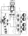
- the hydraulic adjustment unit 400 shown in FIG. 4 includes a hydraulic adjustment apparatus 10, a first hydraulic chamber 16, a second hydraulic chamber 17, a first brake pipe 110, a second brake pipe 120, a third brake pipe 130, a first control valve 111, and a second control valve 121.
- the hydraulic adjustment apparatus 10 has bidirectional pressurization/depressurization function, and the hydraulic adjustment apparatus 10 includes the first hydraulic chamber 16 and the second hydraulic chamber 17.
- the second hydraulic chamber 17 is connected to the first brake pipe 110 and the second brake pipe 120.
- the first brake pipe 110 is used to provide a braking force for a first group of brake wheel cylinders 28 and 29 in a brake system.
- the second brake pipe 120 is used to provide a braking force for a second group of brake wheel cylinders 26 and 27 in the brake system.
- the first brake pipe 110 is provided with a first control valve 111.
- a closed-open status of the first control valve 111 controls a closed-open status of the first brake pipe 110.
- the second brake pipe 120 is provided with a second control valve 121.
- a closed-open status of the second control valve 121 controls a closed-open status of the second brake pipe 120.
- That the closed-open status of the first control valve 111 controls the closed-open status of the first brake pipe 110 may be understood as follows: When the first control valve 111 is in an open state, the first brake pipe 110 is open, and the brake fluid cannot flow to the first group of brake wheel cylinders 28 and 29 through the first brake pipe 110.
- That the closed-open status of the second control valve 121 controls the closed-open status of the second brake pipe 120 may be understood as follows: When the second control valve 121 is in the open state, the second brake pipe 120 is open, and the brake fluid cannot flow to the second group of brake wheel cylinders 26 and 27 through the second brake pipe 120.
- the first group of brake wheel cylinders 28 and 29 may include a brake wheel cylinder of a right front wheel and a brake wheel cylinder of a left front wheel of the automobile.
- the second group of brake wheel cylinders 26 and 27 may include a brake wheel cylinder of a right rear wheel and a brake wheel cylinder of a left rear wheel of the automobile.
- the hydraulic brake units may be understood as being arranged in an H-shaped in the automobile.
- the first group of brake wheel cylinders 28 and 29 may include a brake wheel cylinder of a right front wheel and a brake wheel cylinder of a left rear wheel of the automobile.
- the second group of brake wheel cylinders 26 and 27 may include a brake wheel cylinder of a right rear wheel and a brake wheel cylinder of a left front wheel of the automobile.
- the hydraulic brake units may be understood as being arranged in an X-shaped in the automobile.
- the second hydraulic chamber 17 is connected to the first brake pipe 110 and the second brake pipe 120 may be understood as follows:
- the second hydraulic chamber 17 is directly connected to the first brake pipe 110 and the second brake pipe 120. That is, the fourth hydraulic adjustment port 11b of the second hydraulic chamber 17 is a pressure inlet port of the first brake pipe 110, and the fourth hydraulic adjustment port 11b of the second hydraulic chamber 17 is a pressure inlet port of the second brake pipe 120.
- the first brake pipe 110 is in communication with the second brake pipe 120.
- the second hydraulic chamber 17 is connected to the first brake pipe 110 and the second brake pipe 120 through a section of pipe. That is, the second hydraulic chamber 17 is connected to the first brake pipe 110 and the second brake pipe 120 through a fourth brake pipe 140. As shown in FIG. 1 , the second hydraulic chamber 17 is connected to a first end of the fourth brake pipe 140, a second end of the fourth brake pipe 140 is connected to a first end of the first control valve 111 in the first brake pipe 110, and the second end of the fourth brake pipe 140 is connected to a first end of the second control valve 121 in the second brake pipe 120. In other words, the first brake pipe 110 is in communication with the second brake pipe 120.
- the first hydraulic chamber 16 is connected to the second brake pipe 120 through the third brake pipe 130 in the brake system.
- the first hydraulic chamber 16 provides a braking force for the second group of brake wheel cylinders 26 and 27 through the second brake pipe 120.
- the third brake pipe 130 is in communication with the first brake pipe 110 through the second brake pipe 120.
- the first hydraulic chamber 16 provides a braking force for the first group of brake wheel cylinders 28 and 29 through the first brake pipe 110.
- the first end of the second control valve 121 is a port connected to the fourth brake pipe 140.
- the first end of the second control valve 121 is an end other than the first end of the two ends of the second control valve 121 connected to the second brake pipe 120.
- an interface between the third brake pipe 130 and the second brake pipe 120 is connected to a second end of the second control valve 121.
- the second brake pipe 120 is in communication with the third brake pipe 130, and the closed-open status of the first control valve 111 and that of the second control valve 121 have no impact on a connection or disconnection state between the second brake pipe 120 and the third brake pipe 130.
- the first hydraulic chamber 16 can provide the braking force for the first group of brake wheel cylinders 28 and 29 through the third brake pipe 130, the second brake pipe 120, and the first brake pipe 110.
- the second brake pipe 120 is disconnected from the first brake pipe 110, in other words, the third brake pipe 130 cannot be in communication with the first brake pipe 110 through the second brake pipe 120.
- the first hydraulic chamber 16 can provide the braking force for the second group of brake wheel cylinders 26 and 27 only through the third brake pipe 130 and the second brake pipe 120.
- the second hydraulic chamber 17 provides the braking force for the first group of brake wheel cylinders 28 and 29 through the first brake pipe 110 provided with the first control valve 111, and provides the braking force for the second group of brake wheel cylinders 26 and 27 through the second brake pipe 120 provided with the second control valve 121, thereby helping individually pressurize the first brake pipe 110 and the second brake pipe 120, and avoiding a prior-art case in which the closed-open status of the first brake pipe 110 and that of the second brake pipe 120 cannot be controlled when the braking forces are provided for the first group of brake wheel cylinders 28 and 29 and the second group of brake wheel cylinders 26 and 27 through the first brake pipe 110 and the second brake pipe 120 with one-way valves.
- the second hydraulic chamber 17 may reuse the first brake pipe 110 provided with the first control valve 111 and the second brake pipe 120 provided with the second control valve 121 to determine whether to provide the braking force for the second group of brake wheel cylinders 26 and 27, thereby helping reduce a quantity of control valves in the brake system and reduce costs of the brake system.
- a third control valve 141 may be disposed between a second end of the first control valve 111 and the second end of the second control valve 121, and the third control valve 141 controls connection or disconnection between the second end of the second control valve 121 and the second end of the first control valve 111.
- the third control valve 141 when the third control valve 141 is in the closed state, the second end of the first control valve 111 is electrically connected to the second end of the second control valve 121, and the pressure between the two brake pipes is equalized.
- the third control valve 141 may alternatively not be disposed. This is not limited in this embodiment of this application.
- the third control valve 141 is configured to balance the pressure of the brake fluids in the first brake pipe 110 and the second brake pipe 120, the third control valve 141 may also be referred to as a "pressure equalizing valve 141".
- a first one-way valve 122 may be disposed between a first interface and a second interface.
- the first interface is an interface between the third brake pipe 130 and the second brake pipe 120.
- the second interface is an interface between the third control valve 141 and the second brake pipe 120.
- the first one-way valve 122 allows the brake fluid to flow from the first interface to the second interface, and the first one-way valve 122 prevents the brake fluid from flowing from the second interface to the first interface.
- the first one-way valve 122 may alternatively not be disposed. This is not limited in this embodiment of this application.
- the first hydraulic chamber 16 may provide the braking force for the first group of brake wheel cylinders 27 and 28 through the second brake pipe 120 and the first brake pipe 110.
- the brake fluid flows from the second brake pipe 120 to the first control valve 111 through the second control valve 121, a part of the brake fluid may flow through the fourth brake pipe 140 into the second hydraulic chamber 17. This reduces to some extent efficiency of the first hydraulic chamber 16 in providing the braking force for the first group of brake wheel cylinders 27 and 28.
- the fourth brake pipe 140 may be provided with a fourth control valve 142, to control closing or opening of the fourth brake pipe 140 through closing or opening of the fourth control valve 142.
- the fourth control valve 142 is in the open state.
- the brake fluid entering the fourth brake pipe 140 is blocked by the fourth control valve 142 and cannot flow into the second hydraulic chamber 17.
- the closing or opening of the first control valve 111 and the second control valve 121 can control only whether the first hydraulic chamber 16 provides the braking force for the first group of brake wheel cylinders 28 and 29, but cannot control whether the first hydraulic chamber 16 provides the braking force for the second group of brake wheel cylinders 26 and 27. Therefore, the third brake pipe 130 may be further provided with a fifth control valve 131, and closing or opening of the third brake pipe 130 is controlled by a closed-open status of the fifth control valve 131.
- the third brake pipe 130 is open, and the first hydraulic chamber 16 may provide the braking force for the second group of brake wheel cylinders 26 and 27 through the third brake pipe 130 and the second brake pipe 120.
- the fifth control valve 131 is in the open state, the third brake pipe 130 is closed, and the first hydraulic chamber 16 cannot provide the braking force for the second group of brake wheel cylinders 26 and 27 through the third brake pipe 130 or the second brake pipe 120.
- connection manner between the hydraulic adjustment apparatus and the dual circuit brake system in the embodiments of this application is described above with reference to FIG. 4 to FIG. 6 .
- a connection manner between the hydraulic adjustment apparatus and the fluid storage apparatus 30 is described below with reference to FIG. 7 and FIG. 8 . It should be understood that, for ease of understanding, the following describes a connection manner between the hydraulic adjustment apparatus 10 and the fluid storage apparatus 30 by using the hydraulic adjustment apparatus 10 as an example.
- the second hydraulic chamber 17 is provided with a first inlet pipe 170 connected to the fluid storage apparatus 30, and the first hydraulic chamber 16 is provided with no inlet pipe connected to the fluid storage apparatus 30.
- FIG. 7 is a schematic diagram of a connection manner 1 between a fluid storage apparatus and a hydraulic adjustment apparatus 10 according to an embodiment of this application.
- the first inlet pipe is provided with a one-way valve 171, and the one-way valve 171 allows brake fluid in the first inlet pipe to flow from the fluid storage apparatus 30 to the second hydraulic chamber 17.
- a first hydraulic adjustment port (also referred to as an "outlet port") 14a in the first hydraulic chamber 16 is connected to a first outlet pipe 180.
- a part of the brake fluid in the second hydraulic chamber 17 flows into the dual circuit brake system and a part of the brake fluid in the second hydraulic chamber 17 flows into a third brake pipe 130 through the second control valve 121, and flows into the first hydraulic chamber 16 through the third brake pipe 130.
- an inlet pipe of the first hydraulic chamber 16 is the third brake pipe 130 in a forward pressurization process.
- the first hydraulic chamber 16 is provided with a second inlet pipe 190 connected to the fluid storage apparatus 30, and the second hydraulic chamber 17 is provided with a first inlet pipe 170 connected to the fluid storage apparatus 30.
- FIG. 8 is a schematic diagram of a connection manner 2 between a fluid storage apparatus and a hydraulic adjustment apparatus 10 according to an embodiment of this application.
- the first inlet pipe is provided with a one-way valve 171, and the one-way valve 171 allows brake fluid in the first inlet pipe to flow from the fluid storage apparatus 30 to the second hydraulic chamber 17.
- a first hydraulic adjustment port (also referred to as an "outlet port") 14a in the first hydraulic chamber 16 is connected to a first outlet pipe 180.
- the second inlet pipe 190 is provided with a one-way valve 191.
- the one-way valve 191 allows brake fluid in the second inlet pipe 190 to flow from the fluid storage apparatus 30 to the first hydraulic chamber 16, and prevents the brake fluid in the second inlet pipe 190 from flowing from the first hydraulic chamber 16 to the fluid storage apparatus 30.
- a part of the brake fluid in the second hydraulic chamber 17 flows into the dual circuit brake system and a part of the brake fluid in the second hydraulic chamber 17 flows into a third brake pipe 130 through the second control valve 121, and flows into the first hydraulic chamber 16 through the third brake pipe 130.
- an inlet pipe of the first hydraulic chamber 16 is the third brake pipe 130 in a forward pressurization process.
- a connection manner between the hydraulic adjustment apparatus 10 and a dual circuit brake pipe, and a connection manner between the hydraulic adjustment apparatus 10 and the fluid storage apparatus 30 are described above with reference to FIG. 2(a) and FIG. 2(b) to FIG. 8 .
- the hydraulic adjustment units 400 to 600 shown above may be arbitrarily combined with the hydraulic adjustment units 700 and 800.
- a mechanism in which a braking force is provided by a hydraulic adjustment apparatus 10 in a brake system is described below by using a combination of the hydraulic adjustment unit 400 and the hydraulic adjustment unit 800, a combination of the hydraulic adjustment unit 500 and the hydraulic adjustment unit 800, and a combination of the hydraulic adjustment unit 600 and the hydraulic adjustment unit 800 as examples, respectively.
- a manual braking mode triggered by a driver by stepping on a brake pedal a wire control braking mode triggered by a driver by stepping on a brake pedal, and a driverless braking mode in an automatic driving scenario can also be implemented.
- a principle of a braking process in the foregoing manual braking mode is similar to that of a braking process in a manual braking mode in an existing brake system. For brevity, details are not described again. The following mainly describes a bidirectional pressurization process and a bidirectional depressurization process of the pressure adjustment apparatus 10 in the wire control braking mode and the driverless braking mode.
- FIG. 9 is a schematic diagram of a hydraulic adjustment unit according to an embodiment of this application.
- a function implemented by a master cylinder pressurization and adjustment unit 910 in the hydraulic adjustment unit 900 shown in FIG. 9 is a manual braking mode and a wire control braking mode requiring participation of a driver.
- a control valve 915 and a control valve 916 are in an open state, and correspondingly, a hydraulic adjustment apparatus 10 provides a braking force for a dual circuit brake system based on a pedal stroke detected by a pedal stroke sensor 918 or pressure of the brake fluid detected by a pressure sensor 914.
- the control valve 915 and the control valve 916 are in a closed state, and the brake fluid provides a braking force for brake wheel cylinders 26, 27, 28, and 29 through a brake pipe 160 and a brake pipe 150.
- a first control valve 111, a second control valve 121, a third control valve 141, and inlet valves 920 corresponding to the brake wheel cylinders 26, 27, 28, and 29 are in a closed state.
- the control valve 915, the control valve 916, and outlet valves 930 corresponding to the brake wheel cylinders 26, 27, 28, and 29 are in an open state.
- a driving apparatus 15 drives a piston 12 to compress a volume of a second hydraulic chamber 17, to press brake fluid in the second hydraulic chamber 17 into the brake pipe 150 and the brake pipe 160 through a first brake pipe 110 and a second brake pipe 120 respectively, into the brake wheel cylinders 28 and 29 through the brake pipe 150, and into the brake wheel cylinders 26 and 27 through the brake pipe 160.
- a part of the brake fluid may also enter a first hydraulic chamber 16 through a third brake pipe 130 to replenish the first hydraulic chamber 16, thereby reducing a driving force of the driving apparatus 15 to drive the piston 12.
- brake fluid in a fluid storage apparatus 30 may also enter the first hydraulic chamber 16 through a second oil inlet pipe 190, to replenish the first hydraulic chamber 16, thereby reducing the driving force of the driving apparatus 15 to drive the piston 12.
- the driving apparatus 15 drives the piston 12 to compress a volume of the first hydraulic chamber 16, to press a part of the brake fluid in the first hydraulic chamber 16 into the brake pipe 160 through the third brake pipe 130 and the second brake pipe 120, to provide a braking force for the second group of brake wheel cylinders 26 and 27.
- the other part of the brake fluid in the first hydraulic chamber 16 enters the second brake pipe 120 through the third brake pipe 130 and the second brake pipe 120 that are in communication with each other, enters the first brake pipe 110 through the second control valve 121 and the first control valve 111, and provides a braking force for the first group of brake wheel cylinders 28 and 29 through the brake pipe 150.
- the brake fluid in the fluid storage apparatus 30 may also enter the second hydraulic chamber 17 through a first oil inlet pipe 170, to replenish the second hydraulic chamber 17, thereby reducing the driving force of the driving apparatus 15 to drive the piston 12.
- control valve 915, the control valve 916, the inlet valves 920 corresponding to the brake wheel cylinders 26, 27, 28, and 29, and the outlet valves 930 corresponding to the brake wheel cylinders 26, 27, 28, and 29 are in the open state, and the first control valve 111, the second control valve 121, and the third control valve 141 are in the closed state.
- the driving apparatus 15 drives the piston 12 to compress the volume of the first hydraulic chamber 16, to pump the brake fluid in the brake wheel cylinders 26, 27, 28, and 29 into the second hydraulic chamber 17 through the first brake pipe 110. Because the second brake pipe 120 is provided with a first one-way valve 122, after being pumped into the second brake pipe 120, the brake fluid in the brake wheel cylinders 26, 27, 28, and 29 is blocked by the first one-way valve 122, and can flow to the first brake pipe 110 and into the second hydraulic chamber 17 only through the brake pipe in which the third control valve 141 is located.
- the volume of the second hydraulic chamber 17 is the largest.
- the second hydraulic chamber 17 cannot continue to accommodate the brake fluid, and the remaining brake fluid in the brake wheel cylinders 26, 27, 28, and 29 can continue to flow to the second control valve 121 through the first brake pipe 110, flow to the third brake pipe 130 through the second control valve 121, then flow into the second hydraulic chamber 17 through the third brake pipe 130, and flow into the fluid storage apparatus 30 through the first outlet pipe 180.
- the driving apparatus 15 drives the piston 12 to compress the volume of the second hydraulic chamber 17, to pump the brake fluid in the second group of brake wheel cylinders 26 and 27 through the second brake pipe 120 into the brake pipe in which the third control valve 141 is located, and then, the brake fluid flows through the brake pipe in which the third control valve 141 is located and flows into the third brake pipe 130 through the first control valve 111 and the second control valve 121.
- the brake fluid in the first group of brake wheel cylinders 28 and 29 is pumped into the first brake pipe 110, flows into the third brake pipe 130 through the first control valve 111 and the second control valve 121, and finally flows into the first hydraulic chamber 16 through the third brake pipe 130.
- the outlet valves 930 corresponding to the brake wheel cylinders 26, 27, 28, and 29 can be controlled to be in the closed state.
- the remaining brake fluid in the brake system can flow through the outlet valves 930 corresponding to the brake wheel cylinders 26, 27, 28, and 29 into the fluid storage apparatus 30 through a depressurization pipe.
- the pressure adjustment apparatus 10 is required to provide a braking force for a braking circuit 950.
- the third control valve 141, the second control valve 121, the control valve 915, the control valve 916, and the outlet valves 930 corresponding to the brake wheel cylinders 26 and 27 are in the open state.
- the first control valve 111 and the outlet valves 930 corresponding to the brake wheel cylinders 28 and 29 are in the closed state.
- the driving apparatus 15 drives the piston 12 to compress the volume of the second hydraulic chamber 17, to press the brake fluid in the second hydraulic chamber 17 into the brake pipe 150 through the first brake pipe 110 and into the brake wheel cylinders 28 and 29 through the brake pipe 150. Because the second control valve 121 and the third control valve 141 in the second brake pipe 120 are in the open state, the brake fluid in the second hydraulic chamber 17 cannot pass through the second brake pipe 120.
- the volume of the first hydraulic chamber 16 increases, and a part of the brake fluid may also enter the first hydraulic chamber 16 through the third brake pipe 130, to replenish the first hydraulic chamber 16, thereby reducing the driving force of the driving apparatus 15 to drive the piston 12.
- brake fluid in a fluid storage apparatus 30 may also enter the first hydraulic chamber 16 through a second oil inlet pipe 190, to replenish the first hydraulic chamber 16, thereby reducing the driving force of the driving apparatus 15 to drive the piston 12.
- the pressure adjustment apparatus 10 is required to provide a braking force for a braking circuit 940.
- the third control valve 141, the first control valve 111, the control valve 915, the control valve 916, and the outlet valves 930 corresponding to the brake wheel cylinders 28, and 29 are in the open state.
- the second control valve 121 and the outlet valves 930 corresponding to the brake wheel cylinders 26 and 27 are in the closed state.
- the driving apparatus 15 drives the piston 12 to compress the volume of the second hydraulic chamber 17, to press the brake fluid in the second hydraulic chamber 17 into the brake pipe 160 through the second brake pipe 120 and into the brake wheel cylinders 26 and 27 through the brake pipe 160. Because the first control valve 111 and the third control valve 141 in the first brake pipe 110 are in the open state, the brake fluid in the second hydraulic chamber 17 cannot pass through the first brake pipe 110.
- the volume of the first hydraulic chamber 16 increases, and the brake fluid in the fluid storage apparatus 30 may enter the first hydraulic chamber 16 through the second oil inlet pipe 190, to replenish the first hydraulic chamber 16, thereby reducing the driving force of the driving apparatus 15 to drive the piston 12.
- FIG. 10 is a schematic diagram of a hydraulic adjustment unit according to an embodiment of this application.
- a function implemented by a master cylinder pressurization and adjustment unit 910 in the hydraulic adjustment unit 1000 shown in FIG. 10 is the same as a function implemented by the hydraulic adjustment unit 900 shown in FIG. 9 .
- FIG. 9 details are not described below.
- the pressure adjustment apparatus 10 may be divided into a forward pressurization process and a reverse pressurization process in the bidirectional pressurization mode.
- a first control valve 111, a second control valve 121, a fourth control valve 142, and inlet valves 1020 corresponding to brake wheel cylinders 26, 27, 28 and 29 are in a closed state.
- a control valve 915, a control valve 916, and outlet valves 1030 corresponding to the brake wheel cylinders 26, 27, 28 and 29 are in an open state.
- a driving apparatus 15 drives a piston 12 to compress a volume of a second hydraulic chamber 17, to press brake fluid in the second hydraulic chamber 17 into a brake pipe 150 and a brake pipe 160 through a first brake pipe 110 and a second brake pipe 120 respectively, into the brake wheel cylinders 28 and 29 through the brake pipe 150, and into the brake wheel cylinders 26 and 27 through the brake pipe 160.
- a part of the brake fluid may also enter a first hydraulic chamber 16 through a third brake pipe 130 to replenish the first hydraulic chamber 16, thereby reducing a driving force of the driving apparatus 15 to drive the piston 12.
- brake fluid in a fluid storage apparatus 30 may also enter the first hydraulic chamber 16 through a second oil inlet pipe 190, to replenish the first hydraulic chamber 16, thereby reducing the driving force of the driving apparatus 15 to drive the piston 12.
- the first control valve 111, the second control valve 121, and the inlet valves 1020 corresponding to the brake wheel cylinders 26, 27, 28, and 29 are in the closed state.
- the control valve 915, the control valve 916, the outlet valves 1030 corresponding to the brake wheel cylinders 26, 27, 28, and 29, and the fourth control valve 142 are in the open state.
- the driving apparatus 15 drives the piston 12 to compress a volume of the first hydraulic chamber 16, to press a part of the brake fluid in the first hydraulic chamber 16 into the brake pipe 160 through the third brake pipe 130 and the second brake pipe 120, to provide a braking force for the second group of brake wheel cylinders 26 and 27.
- the other part of the brake fluid in the first hydraulic chamber 16 enters the second brake pipe 120 through the third brake pipe 130 and the second brake pipe 120 that are in communication with each other, enters the first brake pipe 110 through the second control valve 121 and the first control valve 111, and provides a braking force for the first group of brake wheel cylinders 28 and 29 through the brake pipe 150.
- the brake fluid flows through the second control valve 121, because the fourth control valve 142 is in the open state, the brake fluid is prevented from flowing into the second hydraulic chamber 17 through a fourth brake pipe 140.
- the brake fluid in the fluid storage apparatus 30 may also enter the second hydraulic chamber 17 through a first oil inlet pipe 170, to replenish the second hydraulic chamber 17, thereby reducing the driving force of the driving apparatus 15 to drive the piston 12.
- the pressure adjustment apparatus 10 may be divided into a forward pressurization process and a reverse pressurization process in the bidirectional depressurization mode.
- the fourth control valve 142, the control valve 915, the control valve 916, the inlet valves 1020 corresponding to the brake wheel cylinders 26, 27, 28, and 29, and the outlet valves 1030 corresponding to the brake wheel cylinders 26, 27, 28, and 29 are in the open state.
- the first control valve 111 and the second control valve 121 are in the closed state.
- the driving apparatus 15 drives the piston 12 to compress the volume of the first hydraulic chamber 16, to pump the brake fluid in the brake wheel cylinders 26, 27, 28 and 29 into the second hydraulic chamber 17 through the first brake pipe 110 and the second brake pipe 120 separately.
- the volume of the second hydraulic chamber 17 is the largest.
- the second hydraulic chamber 17 cannot continue to accommodate the brake fluid, and the remaining brake fluid in the first group of brake wheel cylinders 28 and 29 can continue to flow to the second control valve 121 through the first brake pipe 110, flow to the third brake pipe 130 through the second control valve 121, then flow into the second hydraulic chamber 17 through the third brake pipe 130, and flow into the fluid storage apparatus 30 through a first outlet pipe 180.
- the remaining brake fluid in the second group of brake wheel cylinders 26 and 27 can continue to flow to the third brake pipe 130 through the second brake pipe 120, flow into the second hydraulic chamber 16 through the third brake pipe 130, and flow into the fluid storage apparatus 30 through the first outlet pipe 180.
- the driving apparatus 15 drives the piston 12 to compress the volume of the second hydraulic chamber 17, to pump the brake fluid in the second group of brake wheel cylinders 26 and 27 into the third brake pipe 130 through the second brake pipe 120 and into the first hydraulic chamber 16 through the third brake pipe 130.
- the brake fluid in the first group of brake wheel cylinders 28 and 29 is pumped into the first brake pipe 110, flows into the third brake pipe 130 through the first control valve 111 and the second control valve 121, and finally flows into the first hydraulic chamber 16 through the third brake pipe 130.
- the volume of the first hydraulic chamber 16 is the largest, and the first hydraulic chamber 16 cannot continue to accommodate the brake fluid.
- the outlet valves 1030 corresponding to the brake wheel cylinders 26, 27, 28, and 29 can be controlled to be in the closed state.
- the remaining brake fluid in the brake system can flow through the outlet valves 1030 corresponding to the brake wheel cylinders 26, 27, 28, and 29 into the fluid storage apparatus 30 through a depressurization pipe.
- the pressure adjustment apparatus 10 is required to provide a braking force for a braking circuit 1050.
- the second control valve 121, the control valve 915, the control valve 916, and the outlet valves 1030 corresponding to the brake wheel cylinders 26 and 27 are in the open state.
- the third control valve 141, the first control valve 111, and the outlet valves 1030 corresponding to the brake wheel cylinders 28 and 29 are in the closed state.
- the driving apparatus 15 drives the piston 12 to compress the volume of the second hydraulic chamber 17, to press the brake fluid in the second hydraulic chamber 17 into the brake pipe 150 through the first brake pipe 110 and into the brake wheel cylinders 28 and 29 through the brake pipe 150. Because the second control valve 121 in the second brake pipe 120 is in the open state, the brake fluid in the second hydraulic chamber 17 cannot pass through the second brake pipe 120.
- the volume of the first hydraulic chamber 16 increases, and the brake fluid in the fluid storage apparatus 30 may enter the first hydraulic chamber 16 through the second oil inlet pipe 190, to replenish the first hydraulic chamber 16, thereby reducing the driving force of the driving apparatus 15 to drive the piston 12.
- the pressure adjustment apparatus 10 is required to provide a braking force for a braking circuit 1040.
- the first control valve 111, the control valve 915, the control valve 916, and the outlet valves 1030 corresponding to the brake wheel cylinders 28, and 29 are in the open state.
- the fourth control valve 142, the second control valve 121, and the outlet valves 1030 corresponding to the brake wheel cylinders 26 and 27 are in the closed state.
- the driving apparatus 15 drives the piston 12 to compress the volume of the second hydraulic chamber 17, to press the brake fluid in the second hydraulic chamber 17 into the brake pipe 160 through the second brake pipe 120 and into the brake wheel cylinders 26 and 27 through the brake pipe 160. Because the first control valve 111 in the first brake pipe 110 is in the open state, the brake fluid in the second hydraulic chamber 17 cannot pass through the first brake pipe 110.
- the brake fluid in the fluid storage apparatus 30 may enter the first hydraulic chamber 16 through the second oil inlet pipe 190, to replenish the first hydraulic chamber 16, thereby reducing the driving force of the driving apparatus 15 to drive the piston 12.
- a part of the brake fluid in the second brake pipe 120 may also enter the first hydraulic chamber 16 through the third brake pipe 130, to replenish the first hydraulic chamber 16, thereby reducing the driving force of the driving apparatus 15 to drive the piston 12.
- FIG. 11 is a schematic diagram of a hydraulic adjustment unit according to an embodiment of this application.
- a function implemented by a master cylinder pressurization and adjustment unit 910 in the hydraulic adjustment unit 1100 shown in FIG. 11 is the same as a function implemented by the hydraulic adjustment unit 900 shown in FIG. 9 .
- FIG. 9 details are not described below.
- the pressure adjustment apparatus 10 may be divided into a forward pressurization process and a reverse pressurization process in the bidirectional pressurization mode.
- a first control valve 111, a second control valve 121, a fourth control valve 142, and inlet valves 1120 corresponding to brake wheel cylinders 26, 27, 28, and 29 are in a closed state.
- a fifth control valve 131, a control valve 915, a control valve 916, and outlet valves 1130 corresponding to the brake wheel cylinders 26, 27, 28, and 29 are in an open state.
- a driving apparatus 15 drives a piston 12 to compress a volume of a second hydraulic chamber 17, to press brake fluid in the second hydraulic chamber 17 into a brake pipe 150 and a brake pipe 160 through a first brake pipe 110 and a second brake pipe 120 respectively, into the brake wheel cylinders 28 and 29 through the brake pipe 150, and into the brake wheel cylinders 26 and 27 through the brake pipe 160.
- brake fluid in a fluid storage apparatus 30 may enter a first hydraulic chamber 16 through a second oil inlet pipe 190, to replenish the first hydraulic chamber 16, thereby reducing a driving force of the driving apparatus 15 to drive the piston 12.
- brake fluid in the second brake pipe 120 cannot enter the first hydraulic chamber 16 through a third brake pipe 130.
- the first control valve 111, the second control valve 121, the fifth control valve 131, and the inlet valves 1120 corresponding to the brake wheel cylinders 26, 27, 28, and 29 are in the closed state.
- the control valve 915, the control valve 916, the outlet valves 1130 corresponding to the brake wheel cylinders 26, 27, 28, and 29, and the fourth control valve 142 are in the open state.
- the driving apparatus 15 drives the piston 12 to compress a volume of the first hydraulic chamber 16, to press a part of the brake fluid in the first hydraulic chamber 16 into the brake pipe 160 through the third brake pipe 130 and the second brake pipe 120, to provide a braking force for the second group of brake wheel cylinders 26 and 27.
- the other part of the brake fluid in the first hydraulic chamber 16 enters the second brake pipe 120 through the third brake pipe 130 and the second brake pipe 120 that are in communication with each other, enters the first brake pipe 110 through the second control valve 121 and the first control valve 111, and provides a braking force for the first group of brake wheel cylinders 28 and 29 through the brake pipe 150.
- the brake fluid flows through the second control valve 121, because the fourth control valve 142 is in the open state, the brake fluid is prevented from flowing into the second hydraulic chamber 17 through a fourth brake pipe 140.
- the brake fluid in the fluid storage apparatus 30 may also enter the second hydraulic chamber 17 through a first oil inlet pipe 170, to replenish the second hydraulic chamber 17, thereby reducing the driving force of the driving apparatus 15 to drive the piston 12.
- the pressure adjustment apparatus 10 may be divided into a forward pressurization process and a reverse pressurization process in the bidirectional depressurization mode.
- the fourth control valve 142, the control valve 915, the control valve 916, the inlet valves 1120 corresponding to the brake wheel cylinders 26, 27, 28, and 29, and the outlet valves 1130 corresponding to the brake wheel cylinders 26, 27, 28, and 29 are in the open state.
- the fifth control valve 131, the first control valve 111, and the second control valve 121 are in the closed state.
- the driving apparatus 15 drives the piston 12 to compress the volume of the first hydraulic chamber 16, to pump the brake fluid in the brake wheel cylinders 26, 27, 28 and 29 into the second hydraulic chamber 17 through the first brake pipe 110 and the second brake pipe 120 separately.
- the volume of the second hydraulic chamber 17 is the largest.
- the second hydraulic chamber 17 cannot continue to accommodate the brake fluid, and the remaining brake fluid in the first group of brake wheel cylinders 28 and 29 can continue to flow to the second control valve 121 through the first brake pipe 110, and flow to the third brake pipe 130 through the second control valve 121.
- the fifth control valve 131 is in the closed state, the brake fluid can flow into the second hydraulic chamber 17 through the third brake pipe 130, and flow into the fluid storage apparatus 30 through a first outlet pipe 180.
- the remaining brake fluid in the second group of brake wheel cylinders 26 and 27 can continue to flow to the third brake pipe 130 through the second brake pipe 120, flow into the second hydraulic chamber 17 through the third brake pipe 130, and flow into the fluid storage apparatus 30 through the first outlet pipe 180.
- the driving apparatus 15 drives the piston 12 to compress the volume of the second hydraulic chamber 17, to pump the brake fluid in the second group of brake wheel cylinders 26 and 27 into the third brake pipe 130 through the second brake pipe 120 and into the first hydraulic chamber 16 through the third brake pipe 130.
- the brake fluid in the first group of brake wheel cylinders 28 and 29 is pumped into the first brake pipe 110, flows into the third brake pipe 130 through the first control valve 111 and the second control valve 121, and finally flows into the first hydraulic chamber 16 through the third brake pipe 130.
- the volume of the first hydraulic chamber 16 is the largest, and the first hydraulic chamber 16 cannot continue to accommodate the brake fluid.
- the outlet valves 1130 corresponding to the brake wheel cylinders 26, 27, 28, and 29 can be controlled to be in the closed state.
- the remaining brake fluid in the brake system can flow through the outlet valves 1130 corresponding to the brake wheel cylinders 26, 27, 28, and 29 into the fluid storage apparatus 30 through a depressurization pipe.
- the pressure adjustment apparatus 10 is required to provide a braking force for a braking circuit 1150.
- the second control valve 121, the control valve 915, the control valve 916, the outlet valves 1130 corresponding to the brake wheel cylinders 26 and 27, and the fifth control valve 131 are in the open state.
- the third control valve 141, the first control valve 111, and the outlet valves 1130 corresponding to the brake wheel cylinders 28 and 29 are in the closed state.
- the driving apparatus 15 drives the piston 12 to compress the volume of the second hydraulic chamber 17, to press the brake fluid in the second hydraulic chamber 17 into the brake pipe 150 through the first brake pipe 110 and into the brake wheel cylinders 28 and 29 through the brake pipe 150. Because the second control valve 121 in the second brake pipe 120 is in the open state, the brake fluid in the second hydraulic chamber 17 cannot pass through the second brake pipe 120.
- the volume of the first hydraulic chamber 16 increases, and the brake fluid in the fluid storage apparatus 30 may enter the first hydraulic chamber 16 through the second oil inlet pipe 190, to replenish the first hydraulic chamber 16, thereby reducing the driving force of the driving apparatus 15 to drive the piston 12.
- the pressure adjustment apparatus 10 is required to provide a braking force for a braking circuit 1140.
- the first control valve 111, the control valve 915, the control valve 916, the outlet valves 1130 corresponding to the brake wheel cylinders 26, 27, 28, and 29, and the fifth control valve 131 are in the open state.
- the fourth control valve 142, the second control valve 121, and the outlet valves 1130 corresponding to the brake wheel cylinders 26 and 27 are in the closed state.
- the driving apparatus 15 drives the piston 12 to compress the volume of the second hydraulic chamber 17, to press the brake fluid in the second hydraulic chamber 17 into the brake pipe 160 through the second brake pipe 120 and into the brake wheel cylinders 26 and 27 through the brake pipe 160. Because the first control valve 111 in the first brake pipe 110 is in the open state, the brake fluid in the second hydraulic chamber 17 cannot pass through the first brake pipe 110.
- the volume of the first hydraulic chamber 16 increases, and the brake fluid in the fluid storage apparatus 30 may enter the first hydraulic chamber 16 through the second oil inlet pipe 190, to replenish the first hydraulic chamber 16, thereby reducing the driving force of the driving apparatus 15 to drive the piston 12.
- the brake fluid in the second brake pipe 120 cannot enter the first hydraulic chamber 16 through the third brake pipe 130, thereby helping improve efficiency of the pressure adjustment apparatus 10 in providing the braking force for the braking circuit 1140.
- FIG. 12 is a flowchart of a control method according to an embodiment of this application. The method shown in FIG. 12 includes step 1210 to step 1220.
- a controller generates a control instruction, where the control instruction is used to control a driving apparatus 15.
- the controller sends the control instruction to the driving apparatus 15, and controls the driving apparatus 15 to drive a piston 12 to move along an inner wall of a hydraulic cylinder 11, to increase or decrease pressure of brake fluid in a first group of brake wheel cylinders 28 and 29 and/or a second group of brake wheel cylinders 26 and 27.
- the method further includes: When a braking circuit for providing a braking force for the first group of brake wheel cylinders 28 and 29 fails, and the first hydraulic chamber 16 is required to provide a braking force for the second group of brake wheel cylinders 26 and 27, the controller controls both a first control valve 111 and the second control valve 121 to be in an open state.
- the first control valve 111 and the second control valve 121 may be open, and the braking force is provided by the first hydraulic chamber 16 for the second group of brake wheel cylinders 26 and 27, thereby helping improve pressurization efficiency of the brake system, and avoiding pressure leakage of the brake fluid caused by the brake fluid flowing into the failed braking circuit.
- the brake system further includes a fourth brake pipe 140.
- the second hydraulic chamber 17 is connected to a first end of the fourth brake pipe 140.
- a second end of the fourth brake pipe 140 is connected to a first end of the second control valve 121.
- the fourth brake pipe 140 is provided with a fourth control valve 142 to control closing or opening of the fourth brake pipe 140.
- the method further includes: When a braking circuit for providing a braking force for the first group of brake wheel cylinders 28 and 29 fails, and the first hydraulic chamber 16 is required to provide a braking force for the second group of brake wheel cylinders 26 and 27, the controller controls both a first control valve 111 and the second control valve 121 to be in an open state and the fourth control valve 142 to be in the open state.
- the first control valve 111, the second control valve 121, and the fourth control valve 142 may be open, and the braking force is provided by the first hydraulic chamber 16 for the second group of brake wheel cylinders 26 and 27, thereby helping improve pressurization efficiency of the brake system, and avoiding pressure leakage of the brake fluid caused by the brake fluid flowing into the failed braking circuit.
- the third brake pipe 130 is provided with a fifth control valve 131, and the fifth control valve 131 controls closing or opening of the third brake pipe 130.
- the method further includes: When a braking circuit for providing the braking force for the first group of brake wheel cylinders 28 and 29 fails, and the first hydraulic chamber 16 is required to provide the braking force for the second group of brake wheel cylinders 26 and 27, the controller controls both the first control valve 111 and the second control valve 121 to be in an open state and the fifth control valve 131 to be in a closed state.
- the first control valve 111 and the second control valve 121 may be open, the fifth control valve 131 is controlled to be closed, and the braking force is provided by the first hydraulic chamber 16 for the second group of brake wheel cylinders 26 and 27, thereby helping improve pressurization efficiency of the brake system, and avoiding pressure leakage of the brake fluid caused by the brake fluid flowing into the failed braking circuit.
- that the controller sends the control instruction to the driving apparatus 15, and controls the driving apparatus 15 to drive the piston 12 to move along an inner wall of the hydraulic cylinder 11, to increase or decrease pressure of brake fluid in the first group of brake wheel cylinders 28 and 29 and/or the second group of brake wheel cylinders 26 and 27 includes: In a process of providing the braking force for the second group of brake wheel cylinders 26 and 27, the controller sends the control instruction to the driving apparatus 15, and controls the driving apparatus 15 to drive the piston 12 to compress a volume of the first hydraulic chamber 16, to press the brake fluid in the first hydraulic chamber 16 into the second group of brake wheel cylinders 26 and 27 through the second brake pipe 120, to increase the pressure of the brake fluid in the second group of brake wheel cylinders 26 and 27.
- the controller controls the piston 12 to compress the volume of the first hydraulic chamber 16 to pressurize the second group of brake wheel cylinders 26 and 27 through the brake fluid in the first hydraulic chamber 16, that is, depressurization is performed on the second group of brake wheel cylinders 26 and 27 individually to improve safety of the brake system.
- the method further includes: When a braking circuit for providing the braking force for the first group of brake wheel cylinders 28 and 29 fails, and the second hydraulic chamber 17 is required to provide the braking force for the second group of brake wheel cylinders 26 and 27, the controller controls the first control valve 111 to be in an open state and controls the second control valve 121 to be in a closed state.
- the first control valve 111 may be open, the second control valve 121 may be closed, and the braking force is provided by the second hydraulic chamber 17 for the second group of brake wheel cylinders 26 and 27, thereby helping improve pressurization efficiency of the brake system, and avoiding pressure leakage of the brake fluid caused by the brake fluid flowing into the failed braking circuit.
- the brake system further includes a fourth brake pipe 140.
- the second hydraulic chamber 17 is connected to a first end of the fourth brake pipe 140.
- a second end of the fourth brake pipe 140 is connected to a first end of the second control valve 121.
- the fourth brake pipe 140 is provided with a fourth control valve 142 to control closing or opening of the fourth brake pipe 140.
- the method further includes: When a braking circuit for providing the braking force for the first group of brake wheel cylinders 28 and 29 fails, and the second hydraulic chamber 17 is required to provide the braking force for the second group of brake wheel cylinders 26 and 27, the controller controls the first control valve 111 to be in an open state and controls the second control valve 121 and the fourth control valve 142 to be in a closed state.
- the first control valve 111 may be open, the second control valve 121 and the fourth control valve 142 may be closed, and the braking force is provided by the second hydraulic chamber 17 for the second group of brake wheel cylinders 26 and 27, thereby helping improve pressurization efficiency of the brake system, and avoiding pressure leakage of the brake fluid caused by the brake fluid flowing into the failed braking circuit.
- the third brake pipe 130 is provided with a fifth control valve 131, and the fifth control valve 131 controls closing or opening of the third brake pipe 130.
- the method further includes: When a braking circuit for providing the braking force for the first group of brake wheel cylinders 28 and 29 fails, and the first hydraulic chamber 16 is required to provide the braking force for the second group of brake wheel cylinders 26 and 27, the controller controls the second control valve 121 to be in an open state and controls the first control valve 111 and the fifth control valve 131 to be in the open state.
- the first control valve 111 and the fifth control valve 131 may be open, the second control valve 121 may be closed, and the braking force is provided by the second hydraulic chamber 17 for the second group of brake wheel cylinders 26 and 27, thereby helping improve pressurization efficiency of the brake system, and avoiding pressure leakage of the brake fluid caused by the brake fluid flowing into the failed braking circuit.
- that the controller sends the control instruction to the driving apparatus 15, and controls the driving apparatus 15 to drive the piston 12 to move along an inner wall of the hydraulic cylinder 11, to increase or decrease pressure of brake fluid in the first group of brake wheel cylinders 28 and 29 and/or the second group of brake wheel cylinders 26 and 27 includes: In a process of providing the braking force for the second group of brake wheel cylinders 26 and 27, the controller sends the control instruction to the driving apparatus 15, and controls the driving apparatus 15 to drive the piston 12 to compress a volume of the second hydraulic chamber 17, to press the brake fluid in the second hydraulic chamber 17 into the second group of brake wheel cylinders 26 and 27 through the second brake pipe 120, to increase the pressure of the brake fluid in the second group of brake wheel cylinders 26 and 27.
- the controller controls the piston 12 to compress the volume of the second hydraulic chamber 17 to pressurize the second group of brake wheel cylinders 26 and 27 through the brake fluid in the second hydraulic chamber 17, that is, pressurization is performed on the second group of brake wheel cylinders 26 and 27 individually to improve safety of the brake system.
- the method further includes: When a braking circuit for providing the braking force for the second group of brake wheel cylinders 26 and 27 fails, and the second hydraulic chamber 17 is required to provide the braking force for the first group of brake wheel cylinders 28 and 29, the controller controls the first control valve 111 to be in an open state and controls the second control valve 121 to be in a closed state.
- the first control valve 111 may be open, the second control valve 121 may be closed, and the braking force is provided by the second hydraulic chamber 17 for the second group of brake wheel cylinders 26 and 27, thereby helping improve pressurization efficiency of the brake system, and avoiding pressure leakage of the brake fluid caused by the brake fluid flowing into the failed braking circuit.
- the brake system further includes a fourth brake pipe 140.
- the second hydraulic chamber 17 is connected to a first end of the fourth brake pipe 140.
- a second end of the fourth brake pipe 140 is connected to a first end of the second control valve 121.
- the fourth brake pipe 140 is provided with a fourth control valve 142 to control closing or opening of the fourth brake pipe 140.
- the method further includes: When a braking circuit for providing the braking force for the second group of brake wheel cylinders 26 and 27 fails, and the second hydraulic chamber 17 is required to provide the braking force for the first group of brake wheel cylinders 28 and 29, the controller controls the second control valve 121 to be in an open state and controls the first control valve 111 and the fourth control valve 142 to be in a closed state.
- the second control valve 121 may be open, the first control valve 111 and the fourth control valve 142 may be closed, and the braking force is provided by the second hydraulic chamber 17 for the second group of brake wheel cylinders 26 and 27, thereby helping improve pressurization efficiency of the brake system, and avoiding pressure leakage of the brake fluid caused by the brake fluid flowing into the failed braking circuit.
- the third brake pipe 130 is provided with a fifth control valve 131, and the fifth control valve 131 controls closing or opening of the third brake pipe 130.
- the method further includes: When a braking circuit for providing the braking force for the first group of brake wheel cylinders 28 and 29 fails, and the second hydraulic chamber 17 is required to provide the braking force for the second group of brake wheel cylinders 26 and 27, the controller controls both the first control valve 111 and the fifth control valve 131 to be in a closed state and the second control valve 121 to be in an open state.
- the second control valve 121 may be open, the first control valve 111 and the fifth control valve 131 may be closed, and the braking force is provided by the second hydraulic chamber 17 for the second group of brake wheel cylinders 26 and 27, thereby helping improve pressurization efficiency of the brake system, and avoiding pressure leakage of the brake fluid caused by the brake fluid flowing into the failed braking circuit.
- that the controller sends the control instruction to the driving apparatus 15, and controls the driving apparatus 15 to drive the piston 12 to move along an inner wall of the hydraulic cylinder 11, to increase or decrease pressure of brake fluid in the first group of brake wheel cylinders 28 and 29 and/or the second group of brake wheel cylinders 26 and 27 includes: In a process of providing the braking force for the first group of brake wheel cylinders 28 and 29, the controller sends the control instruction to the driving apparatus 15, and controls the driving apparatus 15 to drive the piston 12 to compress a volume of the second hydraulic chamber 17, to press the brake fluid in the second hydraulic chamber 17 into the first group of brake wheel cylinders 28 and 29 through the first brake pipe 110, to increase the pressure of the brake fluid in the first group of brake wheel cylinders 28 and 29.
- the controller controls the piston 12 to compress the volume of the second hydraulic chamber 17 to pressurize the first group of brake wheel cylinders 28 and 29 through the brake fluid in the second hydraulic chamber 17, that is, pressurization is performed on the first group of brake wheel cylinders 28 and 29 individually to improve safety of the brake system.
- the braking circuit for providing the braking force for the first group of brake wheel cylinders 28 and 29 is referred to as a "first braking circuit", for example, the braking circuit 950, the braking circuit 1050, or the braking circuit 1150 shown in FIG. 9 to FIG. 11 .
- the braking circuit for providing the braking force for the second group of brake wheel cylinders 26 and 27 is referred to as a "second braking circuit", for example, the braking circuit 940, the braking circuit 1040, or the braking circuit 1140 shown in FIG. 9 to FIG. 11 .
- FIG. 13A and FIG. 13B are a flowchart of a control method according to another embodiment of this application.
- the method shown in FIG. 13A and FIG. 13B includes step 1301 to step 1317.
- a controller determines whether a brake system needs to be braked. If the brake system needs to be braked, step 1302 is performed. If the brake system does not need to be braked, a braking procedure ends.
- a hydraulic adjustment apparatus 10 is powered on and enters an operating state, or the hydraulic adjustment apparatus 10 enters a pressurization mode.
- step 1303 Determine whether the hydraulic adjustment apparatus 10 enters a forward pressurization process. If it is determined that the hydraulic adjustment apparatus 10 enters the forward pressurization process, step 1304 is performed. If it is determined that the hydraulic adjustment apparatus 10 does not enter the forward pressurization process, step 1310 is performed to control a pressure equalizing valve 141 to be in a closed state, to maintain pressure balance of brake fluid in a first braking circuit and a second braking circuit.
- a piston 12 in the hydraulic adjustment apparatus 10 moves leftward, to compress a volume of a second hydraulic chamber 17 in the hydraulic adjustment apparatus 10.
- the hydraulic adjustment apparatus 10 determines whether dual braking circuits in the brake system both operate normally. If the duel braking circuits both operate normally, step 1305 is performed. If a circuit of the dual braking circuits fails, step 1306 is performed.
- the controller controls a control valve in the brake system to be in a first closed-open status, and performs step 1311.
- step 1306 Determine whether the first braking circuit fails. If the first braking circuit fails, step 1307 is performed. If the first braking circuit does not fail, step 1308 is performed.
- the controller controls a control valve in the brake system to be in a second closed-open status, and performs step 1311.
- step 1308 Determine whether the second braking circuit fails. If the second braking circuit fails, step 1309 is performed.
- the controller controls a control valve in the brake system to be in a third closed-open status, and performs step 1311.
- step 1311 The controller determines whether the brake system continues to be pressurized. If the controller determines that the brake system needs to continue to be pressurized, step 1303 is performed again. If the controller determines that the brake system does not need to continue to be pressurized, step 1312 is performed again.
- step 1312 The controller determines whether the brake system enters a pressure maintaining mode. If the controller determines that the brake system needs to enter the pressure maintaining mode, step 1313 is performed. If the controller determines that the brake system does not need to enter the pressure maintaining mode, step 1314 is performed.
- the controller controls the hydraulic adjustment apparatus 10 to stop operating.
- step 1314 The controller determines whether the brake system enters a depressurization mode. If the controller determines that the brake system needs to enter the depressurization mode, step 1315 is performed. If the controller determines that the brake system does not need to enter the depressurization mode, a braking procedure ends.
- the controller controls a control valve in the brake system to be in a fourth closed-open status.
- the controller controls the hydraulic adjustment apparatus 10 to enter a forward depressurization mode. For example, the controller controls the piston 12 of the hydraulic adjustment apparatus 10 to move rightward, to compress a volume of a first hydraulic chamber 16.
- the controller determines that depressurization of the brake system is completed.
- first closed-open status to the fourth closed-open status are slightly different in different hydraulic adjustment units, and closed-open statuses of control valves for different hydraulic adjustment units have been described in detail above, and for brevity, details are not described herein again.
- the hydraulic adjustment apparatus may perform only one depressurization process.
- the hydraulic adjustment apparatus may perform only forward depressurization, and does not implement a reverse depressurization mode. This is not limited in the embodiments of this application.
- control method in the embodiments of this application is described above with reference to FIG. 12 and FIG. 13A and FIG. 13B .
- a control apparatus for performing the foregoing control method is described below with reference to FIG. 14 and FIG. 15 . It should be noted that the apparatus in the embodiments of this application may be applied to any hydraulic adjustment unit or brake system described above, to implement any control method described above. For brevity, details are not described herein again.
- FIG. 14 is a schematic diagram of a control apparatus according to an embodiment of this application.
- the control apparatus 1400 shown in FIG. 14 includes a generation unit 1410 and a sending unit 1420.
- the generation unit 1410 generates a control instruction.
- the control instruction is used to control the driving apparatus 15.
- the sending unit 1420 sends the control instruction to the driving apparatus 15, and controls the driving apparatus 15 to drive the piston 12 to move along an inner wall of the hydraulic cylinder 11, to increase or decrease pressure of brake fluid in the first group of brake wheel cylinders 28 and 29 and/or the second group of brake wheel cylinders 26 and 27.
- the generation unit 1410 may be a processor 1520, the sending unit 1420 may be a communications interface 1530, and a specific structure of the controller is shown in FIG. 15 .
- FIG. 15 is a schematic block diagram of a controller according to another embodiment of this application.
- the controller 1500 shown in FIG. 15 may include a memory 1510, a processor 1520, and a communications interface 1530.
- the memory 1510, the processor 1520, and the communications interface 1530 are connected by using an internal connection path.
- the memory 1510 is configured to store instructions.
- the processor 1520 is configured to execute the instructions stored in the memory 1510, to control the communications interface 1530 to receive/send information.
- the memory 1510 may be coupled to the processor 1520 by using an interface, or may be integrated together with the processor 1520.
- the communications interface 1530 uses an apparatus such as but not limited to an input/output interface (input/output interface), to implement communication between the controller 1500 and another device or a communications network.
- an input/output interface input/output interface
- steps in the foregoing methods can be implemented by using a hardware integrated logical circuit in the processor 1520, or by using instructions in a form of software.
- the method disclosed with reference to the embodiments of this application may be directly performed by a hardware processor, or may be performed by using a combination of hardware in the processor and a software module.
- the software module may be located in a mature storage medium in the art, such as a random access memory, a flash memory, a read-only memory, a programmable read-only memory, an electrically erasable programmable memory, or a register.
- the storage medium is located in the memory 1510, and the processor 1520 reads information in the memory 1510 and completes the steps in the foregoing methods in combination with the hardware of the processor. To avoid repetition, details are not described herein again.
- the processor in the embodiments of this application may be a central processing unit (central processing unit, CPU), or may be another general-purpose processor, a digital signal processor (digital signal processor, DSP), an application-specific integrated circuit (application specific integrated circuit, ASIC), a field programmable gate array (field programmable gate array, FPGA) or another programmable logic device, a discrete gate or a transistor logic device, a discrete hardware component, or the like.
- the general-purpose processor may be a microprocessor, or the processor may be any conventional processor or the like.
- the memory may include a read-only memory and a random access memory, and provide an instruction and data for the processor.
- a part of the processor may further include a non-volatile random access memory.
- the processor may further store information of a device type.
- first”, “second”, and various numeric numbers are merely used for distinguishing for ease of description and are not intended to limit the scope of the embodiments of this application.
- first”, “second”, and various numeric numbers are used for distinguishing between different pipes, through holes, and the like.
- the disclosed system, apparatus, and method may be implemented in other manners.
- the described apparatus embodiment is merely an example.
- division into the units is merely logical function division and may be other division in actual implementation.
- a plurality of units or components may be combined or integrated into another system, or some features may be ignored or not performed.
- the displayed or discussed mutual couplings or direct couplings or communication connections may be implemented by using some interfaces.
- the indirect couplings or communication connections between the apparatuses or units may be implemented in electronic, mechanical, or other forms.
- the units described as separate parts may or may not be physically separate, and parts displayed as units may or may not be physical units, may be located in one position, or may be distributed on a plurality of network units. Some or all of the units may be selected based on actual requirements to achieve the objectives of the solutions of the embodiments.
- the functions When the functions are implemented in a form of a software functional unit and sold or used as an independent product, the functions may be stored in a computer-readable storage medium. Based on such an understanding, the technical solutions of this application essentially, or the part contributing to the conventional technology, or some of the technical solutions may be implemented in a form of a software product.
- the computer software product is stored in a storage medium, and includes several instructions for instructing a computer device (which may be a personal computer, a server, a network device, or the like) to perform all or some of the steps of the methods described in the embodiments of this application.
- the foregoing storage medium includes: any medium that can store program code, such as a USB flash drive, a removable hard disk, a read-only memory (Read-Only Memory, ROM), a random access memory (Random Access Memory, RAM), a magnetic disk, or an optical disc.
- program code such as a USB flash drive, a removable hard disk, a read-only memory (Read-Only Memory, ROM), a random access memory (Random Access Memory, RAM), a magnetic disk, or an optical disc.
Landscapes
- Engineering & Computer Science (AREA)
- Transportation (AREA)
- Mechanical Engineering (AREA)
- Physics & Mathematics (AREA)
- Fluid Mechanics (AREA)
- Regulating Braking Force (AREA)
- Braking Systems And Boosters (AREA)
- Valves And Accessory Devices For Braking Systems (AREA)
Abstract
Description
- This application relates to the field of automobiles, and more specifically, to a hydraulic adjustment unit, a brake system, and a control method.
- A brake system of an automobile is a system that applies specific braking force to wheels of the automobile to perform forced braking on the automobile to some extent. The brake system functions to make a driving automobile forcibly decelerate or even stop as required by a driver or a controller, or to make a stopped automobile stably parked under various road conditions (for example, on a ramp), or to make an automobile driven downhill at a stable speed.
- As a popular brake system, an electro-hydraulic brake (Electro-Hydraulic Brake, EHB) system usually includes a dual circuit brake system and a distributed brake system. For the dual circuit brake system, a hydraulic adjustment apparatus is used to provide a braking force for a first group of brake wheel cylinders through a first brake pipe, and the hydraulic adjustment apparatus is used to provide a braking force for a second group of brake wheel cylinders through a second brake pipe. At present, a hydraulic adjustment apparatus with a bidirectional pressurization function is used as the hydraulic adjustment apparatus in the foregoing dual circuit brake system.
- In a conventional dual circuit brake system, in a process of forward pressurization of a hydraulic adjustment apparatus with a bidirectional pressurization function, a second hydraulic chamber of the hydraulic adjustment apparatus provides a braking force for a first group of vehicles through a first brake pipe provided with a one-way valve, and the second hydraulic chamber provides a braking force for a second group of vehicles through a second brake pipe provided with a one-way valve. In a process of reverse pressurization, a first hydraulic chamber of the hydraulic adjustment apparatus provides a braking force for the first group of vehicle through the first brake pipe provided with the one-way valve, and the first hydraulic chamber provides a braking force for the second group of vehicle through the second brake pipe provided with the one-way valve.
- However, the first brake pipe and the second brake pipe each control a flow direction of brake fluid based on the one-way valve, and cannot control closing or opening of the brake pipe. Consequently, when one of the brake pipes leaks, the brake fluid in the brake system may be lost along the leaked brake pipes, causing the hydraulic adjustment unit to be incapable of pressurizing the brake system, reducing driving safety of the vehicle.
- This application provides a hydraulic adjustment unit, a brake system, and a control method, to individually pressurize any brake pipe in a dual circuit brake pipe, to improve driving safety of a vehicle.
- According to a first aspect, a hydraulic adjustment unit in a brake system is provided, including a
hydraulic adjustment apparatus 10. Thehydraulic adjustment apparatus 10 includes a firsthydraulic chamber 16 and a secondhydraulic chamber 17. The secondhydraulic chamber 17 is connected to afirst brake pipe 110 in the brake system and asecond brake pipe 120 in the brake system. Thefirst brake pipe 110 is used to provide a braking force for a first group ofbrake wheel cylinders second brake pipe 120 is used to provide a braking force for a second group ofbrake wheel cylinders first brake pipe 110 is provided with afirst control valve 111. A closed-open status of thefirst control valve 111 controls a closed-open status of thefirst brake pipe 110. Thesecond brake pipe 120 is provided with asecond control valve 121. A closed-open status of thesecond control valve 121 controls a closed-open status of thesecond brake pipe 120. The firsthydraulic chamber 16 is connected to thesecond brake pipe 120 through athird brake pipe 130 in the brake system. The firsthydraulic chamber 16 provides a braking force for the second group ofbrake wheel cylinders second brake pipe 120. When both thefirst control valve 111 and thesecond control valve 121 are in a closed state, thethird brake pipe 130 is in communication with thefirst brake pipe 110 through thesecond brake pipe 120. The firsthydraulic chamber 16 provides a braking force for the first group ofbrake wheel cylinders first brake pipe 110. - In this embodiment of this application, the second
hydraulic chamber 17 provides the braking force for the first group ofbrake wheel cylinders first brake pipe 110 provided with thefirst control valve 111, and provides the braking force for the second group ofbrake wheel cylinders second brake pipe 120 provided with thesecond control valve 121, thereby helping individually pressurize thefirst brake pipe 110 and thesecond brake pipe 120, and avoiding a prior-art case in which the closed-open status of thefirst brake pipe 110 and that of thesecond brake pipe 120 cannot be controlled when the braking forces are provided for the first group ofbrake wheel cylinders brake wheel cylinders first brake pipe 110 and thesecond brake pipe 120 with one-way valves. - In addition, the second
hydraulic chamber 17 may reuse thefirst brake pipe 110 provided with thefirst control valve 111 and thesecond brake pipe 120 provided with thesecond control valve 121 to determine whether to provide the braking force for the second group ofbrake wheel cylinders - Optionally, the
hydraulic adjustment apparatus 10 is a hydraulic adjustment apparatus with a bidirectional pressurization function. - In a possible implementation, the second
hydraulic chamber 17 is connected to a first end of thefourth brake pipe 140, a second end of thefourth brake pipe 140 is connected to a first end of thesecond control valve 121, and an interface between thethird brake pipe 130 and thesecond brake pipe 120 is connected to a second end of thesecond control valve 121. - In this embodiment of this application, the second
hydraulic chamber 17 provides the braking force for the first group ofbrake wheel cylinders first brake pipe 110 provided with thefirst control valve 111, and provides the braking force for the second group ofbrake wheel cylinders second brake pipe 120 provided with thesecond control valve 121, thereby helping individually pressurize thefirst brake pipe 110 and thesecond brake pipe 120. - In a possible implementation, a second end of the
first control valve 111 is connected to the second end of thesecond control valve 121 by using athird control valve 141. Thethird control valve 141 controls connection or disconnection between the second end of thesecond control valve 121 and the second end of thefirst control valve 111. - In this embodiment of this application, the
third control valve 141 is disposed between the second end of thefirst control valve 111 and the second end of thesecond control valve 121. When thethird control valve 141 is in a closed state, pressure balance of the brake fluid between thefirst brake pipe 110 in which thefirst control valve 111 is located and thesecond brake pipe 120 in which thesecond control valve 121 is located helps improve braking safety of the brake system. - In a possible implementation, a first one-
way valve 122 is disposed between a first interface of the hydraulic adjustment unit and a second interface of the hydraulic adjustment unit. The first interface is an interface between thethird brake pipe 130 and thesecond brake pipe 120. The second interface is an interface between thethird control valve 141 and thesecond brake pipe 120. The first one-way valve 122 allows the brake fluid to flow from the first interface to the second interface, and the first one-way valve 122 prevents the brake fluid from flowing from the second interface to the first interface. - In this embodiment of this application, the first one-
way valve 122 is disposed between the first interface and the second interface, to allow the brake fluid to flow from the first interface to the second interface, and the first one-way valve 122 prevents the brake fluid from flowing from the second interface to the first interface, thereby helping improve braking efficiency of the firsthydraulic chamber 16. - In a possible implementation, the
fourth brake pipe 140 is provided with afourth control valve 142, and closing or opening of thefourth control valve 142 controls closing or opening of thefourth brake pipe 140. - In this embodiment of this application, the
fourth brake pipe 140 is provided with thefourth control valve 142, to control the closing or opening of thefourth brake pipe 140 through the closing or opening of thefourth control valve 142. In this way, in a process in which the firsthydraulic chamber 16 provides the braking force, the brake fluid is prevented from flowing into the secondhydraulic chamber 17 through the fourth brake pipe, thereby helping improve braking efficiency of the firsthydraulic chamber 16. - In a possible implementation, the
third brake pipe 130 is provided with afifth control valve 131, and thefifth control valve 131 controls closing or opening of thethird brake pipe 130. - In this embodiment of this application, the third brake pipe is provided with the
fifth control valve 131, so that the firsthydraulic chamber 16 can provide individual braking for thefirst brake pipe 110 and thesecond brake pipe 120 through closing or opening of thefifth control valve 131, thereby helping improve driving safety of a vehicle. - In a possible implementation, the first
hydraulic chamber 16 and the secondhydraulic chamber 17 are formed by dividing ahydraulic cylinder 11 in the hydraulic adjustment unit by using apiston 12 in the hydraulic adjustment unit. An end portion of the firsthydraulic chamber 16 is provided with a pushrod support portion 14. The pushrod support portion 14 supports apush rod 13 for driving thepiston 12 to move, and the pushrod support portion 14 is provided with a firsthydraulic adjustment port 14a. The firsthydraulic adjustment port 14a is connected to afirst outlet pipe 190 of the brake system. Thepush rod 13 is provided with a secondhydraulic adjustment port 13a. The secondhydraulic adjustment port 13a is in communication with the firsthydraulic chamber 16. When thepiston 12 is located at an inner stop point of a piston stroke, the firsthydraulic adjustment port 14a is in communication with the secondhydraulic adjustment port 13a, and brake fluid in the firsthydraulic chamber 16 is discharged from the firsthydraulic chamber 16 through thefirst outlet pipe 180. When thepiston 12 is located at a position in the piston stroke other than the inner stop point, the firsthydraulic adjustment port 14a is not in communication with the secondhydraulic adjustment port 13a. - In this embodiment of this application, the outlet pipe of the first
hydraulic chamber 16 is arranged on the push rod support portion 14 (corresponding to the firsthydraulic adjustment port 14a) and the push rod 13 (corresponding to the secondhydraulic adjustment port 13a) in sections, so that when thepiston 12 is located at the inner stop point of the piston stroke, the firsthydraulic adjustment port 14a is in communication with the secondhydraulic adjustment port 13a, and when thepiston 12 is located at the position in the piston stroke other than the inner stop point, the firsthydraulic adjustment port 14a is not in communication with the secondhydraulic adjustment port 13a. That is, a state of connection or disconnection between the firsthydraulic adjustment port 14a and the secondhydraulic adjustment port 13a is controlled by the position of thepiston 12 in the piston stroke, thereby avoiding a case of specially configuring a control valve for the firsthydraulic chamber 16 in a conventional hydraulic adjustment apparatus to control closing or opening of the outlet pipe of the firsthydraulic chamber 16, and helping reduce a quantity of control valves in the hydraulic adjustment unit and reduce costs in the hydraulic adjustment unit. - In a possible implementation, the first
hydraulic chamber 16 is connected to afirst inlet pipe 190, and thefirst inlet pipe 190 is configured to press brake fluid in the hydraulic adjustment unit into the firsthydraulic chamber 16. - In a possible implementation, when the
piston 12 is located at an inner stop point of a piston stroke, the brake fluid in the firsthydraulic chamber 16 is discharged from the firsthydraulic chamber 16 through the firsthydraulic adjustment port 14a and the secondhydraulic adjustment port 13a that are in communication with each other. - In this embodiment of this application, the outlet pipe of the first
hydraulic chamber 16 is arranged on the push rod support portion 14 (corresponding to the firsthydraulic adjustment port 14a) and the push rod 13 (corresponding to the secondhydraulic adjustment port 13a) in sections, so that when thepiston 12 is located at the inner stop point of the piston stroke, the firsthydraulic adjustment port 14a is in communication with the secondhydraulic adjustment port 13a, and the brake fluid in the firsthydraulic chamber 16 can be discharged from the firsthydraulic chamber 16 through the firsthydraulic adjustment port 14a and the secondhydraulic adjustment port 13a that are in communication with each other, thereby helping reduce a quantity of control valves in the hydraulic adjustment unit and reduce costs in the hydraulic adjustment unit. - In a possible implementation, a circular or semi-circular first
flow guide groove 13b is provided along an outer circumference of thepush rod 13, and the firstflow guide groove 13b is in communication with the secondhydraulic adjustment port 13a. - In this embodiment of this application, the circular or semi-circular first
flow guide groove 13b is provided on the outer circumference of thepush rod 13, thepiston 12 is located at the inner stop point when thepush rod 13 rotates, and the firsthydraulic adjustment port 14a and the secondhydraulic adjustment port 13a can be in communication with each other through the firstflow guide groove 13b, thereby helping improve performance of the hydraulic adjustment apparatus. - In a possible implementation, a circular or semi-circular second
flow guide groove 13c is provided along an inner circumference of the pushrod support portion 14, and the secondflow guide groove 13c is in communication with the firsthydraulic adjustment port 14a. - In this embodiment of this application, the circular or semi-circular second
flow guide groove 13c is provided on the inner circumference of the pushrod support portion 14, thepiston 12 is located at the inner stop point when thepush rod 13 rotates, and the firsthydraulic adjustment port 14a and the secondhydraulic adjustment port 13a can be in communication with each other through the secondflow guide groove 13c, thereby helping improve performance of the hydraulic adjustment apparatus. - In a possible implementation, the second
hydraulic adjustment port 13a is disposed obliquely on thepush rod 13 and runs through thepush rod 13. A distance between a first end of the secondhydraulic adjustment port 13a and thepiston 12 is shorter than a distance between a second end of the secondhydraulic adjustment port 13a and thepiston 12. The first end is an end through which the secondhydraulic adjustment port 13a is in communication with the firsthydraulic adjustment port 14a. The second end is an end through which the secondhydraulic adjustment port 13a is in communication with the firsthydraulic chamber 16. - In this embodiment of this application, the distance between the first end of the second
hydraulic adjustment port 13a and thepiston 12 is set to be shorter than the distance between the second end of the secondhydraulic adjustment port 13a and thepiston 12, so that the secondhydraulic adjustment port 13a and the firsthydraulic adjustment port 14a that are in communication with each other can be in communication with the firsthydraulic chamber 16. - In a possible implementation, when the
piston 12 is located at the inner stop point, the pushrod support portion 14 is spaced apart from the secondhydraulic adjustment port 13a. - In this embodiment of this application, when the
piston 12 is located at the inner stop point, the pushrod support portion 14 is spaced apart from the secondhydraulic adjustment port 13a, to prevent the pushrod support portion 14 from blocking the secondhydraulic adjustment port 13a, thereby helping the brake fluid flow into the secondhydraulic adjustment port 13a, and improving depressurization efficiency of the hydraulic adjustment apparatus. - According to a second aspect, a brake system is provided, including a first group of
brake wheel cylinders brake wheel cylinders brake wheel cylinders first brake pipe 110, and the hydraulic adjustment unit provides a braking force for the second group ofbrake wheel cylinders second brake pipe 120. - In a possible implementation, the brake system further includes a driving
apparatus 15. The drivingapparatus 15 drives thepiston 12 in thehydraulic adjustment apparatus 10 to move along an inner wall of thehydraulic cylinder 11 of the hydraulic adjustment unit. Thepiston 12 divides thehydraulic cylinder 11 into the firsthydraulic chamber 16 and the secondhydraulic chamber 17. - According to a third aspect, an automobile is provided, including the hydraulic adjustment unit according to the second aspect or the possible implementation of the second aspect. The hydraulic adjustment unit adjusts pressure of brake fluid in a brake pipe in the brake system to control magnitude of a braking force applied to a brake wheel cylinder in the brake system.
- According to a fourth aspect, a method for controlling a brake system is provided. The brake system includes a
hydraulic adjustment apparatus 10 with a bidirectional pressurization function. Ahydraulic cylinder 11 of thehydraulic adjustment apparatus 10 is divided into a firsthydraulic chamber 16 and a secondhydraulic chamber 17 by apiston 12. The secondhydraulic chamber 17 is connected to afirst brake pipe 110 in the brake system and asecond brake pipe 120 in the brake system. Thefirst brake pipe 110 is configured to provide a braking force for a first group ofbrake wheel cylinders second brake pipe 120 is configured to provide a braking force for a second group ofbrake wheel cylinders first brake pipe 110 is provided with afirst control valve 111. A closed-open status of thefirst control valve 111 controls a closed-open status of thefirst brake pipe 110. Thesecond brake pipe 120 is provided with asecond control valve 121. A closed-open status of thesecond control valve 121 controls a closed-open status of thesecond brake pipe 120. The firsthydraulic chamber 16 is connected to thesecond brake pipe 120 through athird brake pipe 130 in the brake system. The firsthydraulic chamber 16 provides a braking force for the second group ofbrake wheel cylinders second brake pipe 120. When both thefirst control valve 111 and thesecond control valve 121 are in a closed state, thethird brake pipe 130 is in communication with thefirst brake pipe 110 through thesecond brake pipe 120. The firsthydraulic chamber 16 provides a braking force for the first group ofbrake wheel cylinders first brake pipe 110. The method includes: A controller generates a control instruction. The control instruction is used to control a drivingapparatus 15. The controller sends the control instruction to the drivingapparatus 15, and controls the drivingapparatus 15 to drive thepiston 12 to move along an inner wall of thehydraulic cylinder 11, to increase or decrease pressure of brake fluid in the first group ofbrake wheel cylinders brake wheel cylinders - In this embodiment of this application, the second
hydraulic chamber 17 provides the braking force for the first group ofbrake wheel cylinders first brake pipe 110 provided with thefirst control valve 111, and provides the braking force for the second group ofbrake wheel cylinders second brake pipe 120 provided with thesecond control valve 121, thereby helping individually pressurize thefirst brake pipe 110 and thesecond brake pipe 120, and avoiding a prior-art case in which the closed-open status of thefirst brake pipe 110 and that of thesecond brake pipe 120 cannot be controlled when the braking forces are provided for the first group ofbrake wheel cylinders brake wheel cylinders first brake pipe 110 and thesecond brake pipe 120 with one-way valves. - In addition, the second
hydraulic chamber 17 may reuse thefirst brake pipe 110 provided with thefirst control valve 111 and thesecond brake pipe 120 provided with thesecond control valve 121 to determine whether to provide the braking force for the second group ofbrake wheel cylinders - In a possible implementation, the method further includes: When a braking circuit for providing the braking force for the first group of
brake wheel cylinders hydraulic chamber 16 is required to provide the braking force for the second group ofbrake wheel cylinders first control valve 111 and thesecond control valve 121 to be in an open state. - In this embodiment of this application, after the braking circuit for providing the braking force for the first group of
brake wheel cylinders first control valve 111 and thesecond control valve 121 may be open, and the braking force is provided by the firsthydraulic chamber 16 for the second group ofbrake wheel cylinders - In a possible implementation, the brake system further includes a
fourth brake pipe 140. The secondhydraulic chamber 17 is connected to a first end of thefourth brake pipe 140. A second end of thefourth brake pipe 140 is connected to a first end of thesecond control valve 121. Thefourth brake pipe 140 is provided with afourth control valve 142 to control closing or opening of thefourth brake pipe 140. The method further includes: When a braking circuit for providing the braking force for the first group ofbrake wheel cylinders hydraulic chamber 16 is required to provide the braking force for the second group ofbrake wheel cylinders first control valve 111 and thesecond control valve 121 to be in an open state and thefourth control valve 142 to be in the open state. - In this embodiment of this application, after the braking circuit for providing the braking force for the first group of
brake wheel cylinders first control valve 111, thesecond control valve 121, and thefourth control valve 142 may be open, and the braking force is provided by the firsthydraulic chamber 16 for the second group ofbrake wheel cylinders - In a possible implementation, the
third brake pipe 130 is provided with afifth control valve 131, and thefifth control valve 131 controls closing or opening of thethird brake pipe 130. The method further includes: When a braking circuit for providing the braking force for the first group ofbrake wheel cylinders hydraulic chamber 16 is required to provide the braking force for the second group ofbrake wheel cylinders first control valve 111 and thesecond control valve 121 to be in an open state and thefifth control valve 131 to be in a closed state. - In this embodiment of this application, after the braking circuit for providing the braking force for the first group of
brake wheel cylinders first control valve 111 and thesecond control valve 121 may be open, thefifth control valve 131 is controlled to be closed, and the braking force is provided by the firsthydraulic chamber 16 for the second group ofbrake wheel cylinders - In a possible implementation, that the controller sends the control instruction to the driving
apparatus 15, and controls the drivingapparatus 15 to drive thepiston 12 to move along an inner wall of thehydraulic cylinder 11, to increase or decrease pressure of brake fluid in the first group ofbrake wheel cylinders brake wheel cylinders brake wheel cylinders apparatus 15, and controls the drivingapparatus 15 to drive thepiston 12 to compress a volume of the firsthydraulic chamber 16, to press the brake fluid in the firsthydraulic chamber 16 into the second group ofbrake wheel cylinders second brake pipe 120, to increase the pressure of the brake fluid in the second group ofbrake wheel cylinders - In this embodiment of this application, after the braking circuit for providing the braking force for the first group of
brake wheel cylinders piston 12 to compress the volume of the firsthydraulic chamber 16 to pressurize the second group ofbrake wheel cylinders hydraulic chamber 16, that is, pressurization is performed on the second group ofbrake wheel cylinders - In a possible implementation, the method further includes: When a braking circuit for providing the braking force for the first group of
brake wheel cylinders hydraulic chamber 17 is required to provide the braking force for the second group ofbrake wheel cylinders first control valve 111 to be in an open state and controls thesecond control valve 121 to be in a closed state. - In this embodiment of this application, after the braking circuit for providing the braking force for the first group of
brake wheel cylinders first control valve 111 may be open, thesecond control valve 121 may be closed, and the braking force is provided by the secondhydraulic chamber 17 for the second group ofbrake wheel cylinders - In a possible implementation, the brake system further includes a
fourth brake pipe 140. The secondhydraulic chamber 17 is connected to a first end of thefourth brake pipe 140. A second end of thefourth brake pipe 140 is connected to a first end of thesecond control valve 121. Thefourth brake pipe 140 is provided with afourth control valve 142 to control closing or opening of thefourth brake pipe 140. The method further includes: When a braking circuit for providing the braking force for the first group ofbrake wheel cylinders hydraulic chamber 17 is required to provide the braking force for the second group ofbrake wheel cylinders first control valve 111 to be in an open state and controls thesecond control valve 121 and thefourth control valve 142 to be in a closed state. - In this embodiment of this application, after the braking circuit for providing the braking force for the first group of
brake wheel cylinders first control valve 111 may be open, thesecond control valve 121 and thefourth control valve 142 may be closed, and the braking force is provided by the secondhydraulic chamber 17 for the second group ofbrake wheel cylinders - In a possible implementation, the
third brake pipe 130 is provided with afifth control valve 131, and thefifth control valve 131 controls closing or opening of thethird brake pipe 130. The method further includes: When a braking circuit for providing the braking force for the first group ofbrake wheel cylinders hydraulic chamber 16 is required to provide the braking force for the second group ofbrake wheel cylinders second control valve 121 to be in an open state and controls thefirst control valve 111 and thefifth control valve 131 to be in the open state. - In this embodiment of this application, after the braking circuit for providing the braking force for the first group of
brake wheel cylinders first control valve 111 and thefifth control valve 131 may be open, thesecond control valve 121 may be closed, and the braking force is provided by the secondhydraulic chamber 17 for the second group ofbrake wheel cylinders - In a possible implementation, that the controller sends the control instruction to the driving
apparatus 15, and controls the drivingapparatus 15 to drive thepiston 12 to move along an inner wall of thehydraulic cylinder 11, to increase or decrease pressure of brake fluid in the first group ofbrake wheel cylinders brake wheel cylinders brake wheel cylinders apparatus 15, and controls the drivingapparatus 15 to drive thepiston 12 to compress a volume of the secondhydraulic chamber 17, to press the brake fluid in the secondhydraulic chamber 17 into the second group ofbrake wheel cylinders second brake pipe 120, to increase the pressure of the brake fluid in the second group ofbrake wheel cylinders - In this embodiment of this application, after the braking circuit for providing the braking force for the first group of
brake wheel cylinders piston 12 to compress the volume of the secondhydraulic chamber 17 to pressurize the second group ofbrake wheel cylinders hydraulic chamber 17, that is, pressurization is performed on the second group ofbrake wheel cylinders - In a possible implementation, the method further includes: When a braking circuit for providing the braking force for the second group of
brake wheel cylinders hydraulic chamber 17 is required to provide the braking force for the first group ofbrake wheel cylinders first control valve 111 to be in an open state and controls thesecond control valve 121 to be in a closed state. - In this embodiment of this application, after the braking circuit for providing the braking force for the second group of
brake wheel cylinders first control valve 111 may be open, thesecond control valve 121 may be closed, and the braking force is provided by the secondhydraulic chamber 17 for the second group ofbrake wheel cylinders - In a possible implementation, the brake system further includes a
fourth brake pipe 140. The secondhydraulic chamber 17 is connected to a first end of thefourth brake pipe 140. A second end of thefourth brake pipe 140 is connected to a first end of thesecond control valve 121. Thefourth brake pipe 140 is provided with afourth control valve 142 to control closing or opening of thefourth brake pipe 140. The method further includes: When a braking circuit for providing the braking force for the second group ofbrake wheel cylinders hydraulic chamber 17 is required to provide the braking force for the first group ofbrake wheel cylinders second control valve 121 to be in an open state and controls thefirst control valve 111 and thefourth control valve 142 to be in a closed state. - In this embodiment of this application, after the braking circuit for providing the braking force for the second group of
brake wheel cylinders second control valve 121 may be open, thefirst control valve 111 and thefourth control valve 142 may be closed, and the braking force is provided by the secondhydraulic chamber 17 for the second group ofbrake wheel cylinders - In a possible implementation, the
third brake pipe 130 is provided with afifth control valve 131, and thefifth control valve 131 controls closing or opening of thethird brake pipe 130. The method further includes: When a braking circuit for providing the braking force for the first group ofbrake wheel cylinders hydraulic chamber 17 is required to provide the braking force for the second group ofbrake wheel cylinders first control valve 111 and thefifth control valve 131 to be in a closed state and thesecond control valve 121 to be in an open state. - In this embodiment of this application, after the braking circuit for providing the braking force for the second group of
brake wheel cylinders second control valve 121 may be open, thefirst control valve 111 and thefifth control valve 131 may be closed, and the braking force is provided by the secondhydraulic chamber 17 for the second group ofbrake wheel cylinders - In a possible implementation, that the controller sends the control instruction to the driving
apparatus 15, and controls the drivingapparatus 15 to drive thepiston 12 to move along an inner wall of thehydraulic cylinder 11, to increase or decrease pressure of brake fluid in the first group ofbrake wheel cylinders brake wheel cylinders brake wheel cylinders apparatus 15, and controls the drivingapparatus 15 to drive thepiston 12 to compress a volume of the secondhydraulic chamber 17, to press the brake fluid in the secondhydraulic chamber 17 into the first group ofbrake wheel cylinders first brake pipe 110, to increase the pressure of the brake fluid in the first group ofbrake wheel cylinders - In this embodiment of this application, after the braking circuit for providing the braking force for the second group of
brake wheel cylinders piston 12 to compress the volume of the secondhydraulic chamber 17 to pressurize the first group ofbrake wheel cylinders hydraulic chamber 17, that is, pressurization is performed on the first group ofbrake wheel cylinders - According to a fifth aspect, a control apparatus is provided. The control apparatus includes a processing unit and a storage unit. The storage unit is configured to store instructions. The processing unit executes the instructions stored in the storage unit, so that the control apparatus performs any possible method in the third aspect.
- Optionally, the control apparatus may be an independent controller in an automobile, or may be a chip with a control function in the automobile. The processing unit may be a processor. The storage unit may be a memory. The memory may be a storage unit (for example, a register or a cache) in a chip, or may be a storage unit (for example, a read-only memory or a random access memory), located outside the chip, in the automobile.
- It should be noted that, in the foregoing controller, the memory is coupled to the processor. That the memory is coupled to the processor may be understood as that the memory is located inside the processor, or the memory is located outside the processor, to be independent of the processor.
- According to a sixth aspect, a computer program product is provided. The computer program product includes computer program code. When the computer program code is run on a computer, the computer is enabled to perform the methods in the foregoing aspects.
- It should be noted that all or some of the computer program code may be stored in a first storage medium. The first storage medium may be encapsulated together with the processor, or may be encapsulated separately with the processor. This is not specifically limited in this embodiment of this application.
- According to a seventh aspect, a computer-readable medium is provided. The computer-readable medium stores computer program code. When the computer program code is run on a computer, the computer is enabled to perform the methods in the foregoing aspects.
-
-
FIG. 1 is a schematic diagram of a hydraulic adjustment apparatus according to an embodiment of this application; -
FIG. 2(a) and FIG. 2(b) are a schematic structural diagram of a first flow guide groove according to an embodiment of this application; -
FIG. 3 is a schematic structural diagram of a second flow guide groove according to an embodiment of this application; -
FIG. 4 is a schematic diagram of a hydraulic adjustment unit according to an embodiment of this application; -
FIG. 5 is a schematic diagram of a hydraulic adjustment unit according to another embodiment of this application; -
FIG. 6 is a schematic diagram of a hydraulic adjustment unit according to another embodiment of this application; -
FIG. 7 is a schematic diagram of a connection manner 1 between a fluid storage apparatus and ahydraulic adjustment apparatus 10 according to an embodiment of this application; -
FIG. 8 is a schematic diagram of a connection manner 2 between a fluid storage apparatus and ahydraulic adjustment apparatus 10 according to an embodiment of this application; -
FIG. 9 is a schematic diagram of a hydraulic adjustment unit according to an embodiment of this application; -
FIG. 10 is a schematic diagram of a hydraulic adjustment unit according to an embodiment of this application; -
FIG. 11 is a schematic diagram of a hydraulic adjustment unit according to an embodiment of this application; -
FIG. 12 is a flowchart of a control method according to an embodiment of this application; -
FIG. 13A andFIG. 13B are a flowchart of a control method according to another embodiment of this application; -
FIG. 14 is a schematic diagram of a control apparatus according to an embodiment of this application; and -
FIG. 15 is a schematic block diagram of a controller according to another embodiment of this application. - The following describes technical solutions of this application with reference to accompanying drawings.
- It should be noted that, an "outlet pipe" and an "inlet pipe" mentioned in the following may correspond to different brake pipes, or may correspond to a same brake pipe. The "outlet pipe" and the "inlet pipe" are distinguished only based on functions of the brake pipes in a brake system. For example, when the "outlet pipe" and the "inlet pipe" correspond to a same first brake pipe, it may be understood that the first brake pipe in the brake system is used to deliver brake fluid in a brake wheel cylinder to a fluid storage apparatus in a process of depressurizing wheels of an automobile. The first brake pipe may be referred to as an "outlet pipe". In a process of pressurizing the wheels of the automobile, the first brake pipe is used to provide brake fluid for the wheels of the automobile, and provide a braking force for the wheels of the automobile. In this case, the first brake pipe may be referred to as an "inlet pipe".
- In addition, an "inlet valve", an "outlet valve", and a "pressure equalizing valve" used in the following are distinguished only based on functions of the control valves in the brake system. A control valve used to control opening or closing of the inlet pipe may be referred to as an "inlet valve" or a "booster valve". A control valve configured to control opening or closing of a fluid return pipe may be referred to as an "outlet valve" or a "pressure reducing valve". A control valve used to isolate a two-stage braking subsystem may be referred to as an "isolation valve". The control valve may be a valve commonly used in an existing brake system, for example, a solenoid valve. This is not specifically limited in the embodiments of this application.
- In addition, after the control valve is connected to the brake pipe, a connection port between the control valve and the brake pipe may be indicated by a first end and a second end, and a flow direction of the brake fluid between the first end and the second end is not limited in this application. For example, the brake fluid may flow from the first end of the control valve to the second end of the control valve when the control valve is in a closed state, or the brake fluid may flow from the second end of the control valve to the first end of the control valve when the control valve is in an open state.
- In addition, a "
first brake pipe 110", a "second brake pipe 120", a "third brake pipe 130", a "fourth brake pipe 140", and other brake pipes used in the following may be construed as one or more sections of brake pipes that implement a particular function. For example, thethird brake pipe 130 is a multi-section brake pipe used to connect a brake master cylinder 3 and abrake wheel cylinder 151 of a first group of wheels. - In addition, when the following describes an architecture such as a brake system and an automobile with reference to the accompanying drawings, the accompanying drawings schematically show two operating states (open or closed) that each control valve can achieve, and do not limit a current operating state of the control valve to that shown in the drawings.
- In addition, when the following describes an architecture such as a hydraulic adjustment unit, a brake system, and an automobile with reference to the accompanying drawings, components having a same function in the accompanying drawings corresponding to the embodiments use the same number. For brevity, functions of the components are not described in each embodiment, and reference may be made to the description of the functions of the components in the entire text.
- For ease of understanding of this application, the following first describes, with reference to
FIG. 1 to FIG. 3 , a hydraulic adjustment apparatus applicable to the embodiments of this application. It should be understood that the solutions in the embodiments of this application are further applicable to another hydraulic adjustment apparatus that has a bidirectional pressurization/depressurization function. This is not limited in the embodiments of this application. -
FIG. 1 is a schematic diagram of a hydraulic adjustment apparatus according to an embodiment of this application. Thehydraulic adjustment apparatus 10 shown inFIG. 1 includes ahydraulic cylinder 11, apiston 12, apush rod 13, and a pushrod support portion 14. - The
piston 12 moves along an inner wall of thehydraulic cylinder 11. Thepiston 12 divides thehydraulic cylinder 11 into a firsthydraulic chamber 16 and a secondhydraulic chamber 17. An end portion of the firsthydraulic chamber 16 is provided with the pushrod support portion 14. The pushrod support portion 14 supports thepush rod 13, and the pushrod support portion 14 is provided with a firsthydraulic adjustment port 14a. Thepush rod 13 is provided with a secondhydraulic adjustment port 13a. A first end of the secondhydraulic adjustment port 13a is in communication with the firsthydraulic chamber 16. When thepiston 12 is located at an inner stop point of a piston stroke, the firsthydraulic adjustment port 14a is in communication with a second end of the secondhydraulic adjustment port 13a. When thepiston 12 is located at a position in the piston stroke other than the inner stop point, the firsthydraulic adjustment port 14a is not in communication with the second end of the secondhydraulic adjustment port 13a. - As shown in
FIG. 1 , the drivingapparatus 15 pushes, through thepush rod 13, thepiston 12 to move along the inner wall of thehydraulic cylinder 11 and form the piston stroke, thehydraulic cylinder 11 is divided by thepiston 12 into two hydraulic chambers: the firsthydraulic chamber 16 and the secondhydraulic chamber 17. A first flow channel connected to the firsthydraulic chamber 16 includes aport 11a and a port 11d. A second flow channel connected to the secondhydraulic chamber 17 includes aport 11c and aport 11b. - The
piston 12 is movably disposed in thehydraulic cylinder 11, one end of thepush rod 13 extends into thehydraulic cylinder 11 and is connected to thepiston 12, and the other end of thepush rod 13 penetrates thehydraulic cylinder 11 and is in transmission connection with the drivingapparatus 15. Driven by the drivingapparatus 15, thepiston 12 is capable of reciprocating movement within thehydraulic cylinder 11 to implement a pressurization or depressurization (depressurization) operation on the brake system. - It should be noted that the
piston 12 may be driven by the drivingapparatus 15, and the drivingapparatus 15 may be another apparatus having a driving capability, for example, a motor. It should be understood that, when the drivingapparatus 15 is a motor, a part of the motor outputs torque. Therefore, in order to convert the torque output by the motor into a linear motion for driving thepush rod 13, the drivingapparatus 15 and thepush rod 13 may be further connected by using a deceleration mechanism or anotherpower conversion mechanism 18. The power conversion mechanism may include, for example, a turbine worm assembly or a ball screw nut assembly. - During the movement of the
piston 12 along the inner wall of thehydraulic cylinder 11, a position at which thepiston 12 is farthest away from a drive shaft (for example, a crankshaft center) of the drivingapparatus 15 is referred to as an "outer stop center". Correspondingly, a position at which thepiston 12 is closest to the drive shaft (for example, the crankshaft center) of the drivingapparatus 15 is referred to as an "inner stop point". A distance between the "outer stop point" and the "inner stop point" is referred to as the piston stroke. - The first
hydraulic chamber 16 and the secondhydraulic chamber 17 are separated by thepiston 12 and are configured so that volumes of the firsthydraulic chamber 16 and the secondhydraulic chamber 17 change with movement of thepiston 12. Specifically, when thepiston 12 moves forward (leftward inFIG. 1 ), the volume of the firsthydraulic chamber 16 is increased and the volume of the secondhydraulic chamber 17 is reduced. When thepiston 12 moves backward (rightward inFIG. 1 ), the volume of the firsthydraulic chamber 16 is reduced and the volume of the secondhydraulic chamber 17 is increased. - Usually, the forward movement of the
piston 12 may be referred to as "forward movement" and the backward movement of thepiston 12 may be referred to as "reverse movement". When thehydraulic adjustment apparatus 10 performs a pressurization operation on the brake system, pressurization of the forward movement may be referred to as forward pressurization and pressurization of the reverse movement may be referred to as reverse pressurization. The forward pressurization and the reverse pressurization are to be further described below when the hydraulic adjustment unit or the brake system including thehydraulic adjustment apparatus 10 is described. - The end portion of the first
hydraulic chamber 16 is provided with the pushrod support portion 14. The pushrod support portion 14 supports thepush rod 13, and the pushrod support portion 14 is provided with the firsthydraulic adjustment port 14a. - It should be noted that, the push
rod support portion 14 and thehydraulic cylinder 11 may be integrally formed, or the pushrod support portion 14 and thehydraulic cylinder 11 may be assembled at a later stage. This is not limited in this embodiment of this application. - Optionally, the push
rod support portion 14 is further provided with a sealing member (not shown), to prevent the brake fluid from flowing out of the firsthydraulic chamber 16 through a gap between thepush rod 13 and the pushrod support portion 14. - The
push rod 13 is provided with the secondhydraulic adjustment port 13a. The firsthydraulic chamber 16 is in communication with the secondhydraulic adjustment port 14a through the firsthydraulic adjustment port 14a when thepiston 12 is located at the inner stop point of the piston stroke. Conversely, when thepiston 12 is located at a position in the piston stroke other than the inner stop point, the firsthydraulic adjustment port 14a is not in communication with the secondhydraulic adjustment port 13a. - That the first
hydraulic chamber 16 is in communication with the secondhydraulic adjustment port 14a through the firsthydraulic adjustment port 14a may be understood as follows: The brake fluid in the firsthydraulic chamber 16 can be discharged from the firsthydraulic chamber 16 through the firsthydraulic adjustment port 14a and the secondhydraulic adjustment port 13a that are in communication with each other. Alternatively, the brake fluid can enter the firsthydraulic chamber 16 through the firsthydraulic adjustment port 14a and the secondhydraulic adjustment port 13a that are in communication with each other. - The first
hydraulic adjustment port 14a and the secondhydraulic adjustment port 13a may be considered as the ports of the foregoing first flow channel in communication with the firsthydraulic chamber 16. - Optionally, the brake fluid in the first
hydraulic chamber 16 may flow into the first hydraulic chamber through the thirdhydraulic adjustment port 11a provided in the first hydraulic chamber. The thirdhydraulic adjustment port 11a is in communication with the firsthydraulic chamber 16 and a brake pipe of the brake system. The brake pipe may be in communication with a brake wheel cylinder of the automobile wheel, and a controller of the brake system can adjust a braking force applied to the wheel by adjusting hydraulic pressure in the brake pipe. - In other words, in a pressurization process, the first
hydraulic chamber 16 can pump the brake fluid into the brake pipe through the thirdhydraulic adjustment port 11a, thereby increasing the braking force applied to the wheel. In a depressurization process, based on a pressure difference in the brake system, the brake fluid in the brake pipe may flow into the firsthydraulic chamber 16 through the thirdhydraulic adjustment port 11a, thereby reducing or canceling the braking force applied to the wheel. - Optionally, the
hydraulic cylinder 11 may be further provided with a fourthhydraulic adjustment port 11b, and the fourth hydraulic adjustment port 1 1b is configured to communicate the secondhydraulic chamber 17 with the brake pipe of the brake system through a pipe. - Similarly, the second
hydraulic chamber 17 can discharge the brake fluid into the brake pipe through the fourthhydraulic adjustment port 11b, and perform a pressurization operation on the brake pipe, thereby increasing the braking force applied to the wheel. The brake fluid in the brake pipe can also be discharged into the secondhydraulic chamber 17 through the fourthhydraulic adjustment port 11b to perform a depressurization operation on the brake pipe, thereby reducing or canceling the braking force applied to the wheel. - The fourth
hydraulic adjustment port 11b may also communicate with the secondhydraulic chamber 17 and the firsthydraulic chamber 16 through the brake pipe. With the above arrangement, when thehydraulic adjustment apparatus 10 performs forward pressurization, a part of the brake fluid in the secondhydraulic chamber 17 can be discharged into the brake pipe to brake the wheel, and the remaining part of the brake fluid can be discharged into the firsthydraulic chamber 16. In this way, a pressure difference between the secondhydraulic chamber 17 and the firsthydraulic chamber 16 can be reduced, working load of the drivingapparatus 15 can be reduced, and a service life of the drivingapparatus 15 can be increased. - The
hydraulic cylinder 11 may be further provided with a fifthhydraulic adjustment port 11c, and the fifthhydraulic adjustment port 11c is configured to discharge the brake fluid supplemented by thefluid storage apparatus 30. - Specifically, the fifth
hydraulic adjustment port 11c is in communication with thefluid storage apparatus 30 through a pipe. During reverse pressurization, in order to reduce the pressure difference between the secondhydraulic chamber 17 and the firsthydraulic chamber 16, in a process of rightward movement of thepiston 12, the brake fluid in thefluid storage apparatus 30 can be replenished into the secondhydraulic chamber 17 in time through the fifthhydraulic adjustment port 11c. - Therefore, the
hydraulic adjustment apparatus 10 provided in this embodiment of this application can implement bidirectional pressurization through forward movement or backward movement, thereby ensuring continuity of the pressurization process, and improving comfort during braking. On the other hand, thehydraulic adjustment apparatus 10 in this embodiment of this application can rapidly generate pressure, to rapidly pressurize the brake system, thereby reducing a control response time of the system, and meeting a control and safety requirement of a vehicle. - Optionally, in order to facilitate communication between the first
hydraulic chamber 16 and the firsthydraulic adjustment port 14a, the secondhydraulic adjustment port 13a may be obliquely provided on thepush rod 13 and run through thepush rod 13. A distance between a fluid inlet of the secondhydraulic adjustment port 13a and thepiston 12 is shorter than a distance between a fluid outlet of the secondhydraulic adjustment port 13a and thepiston 12. - That the distance between the fluid inlet (also referred to as the first end) of the second
hydraulic adjustment port 13a and thepiston 12 is shorter than the distance between the fluid outlet (also referred to as the second end) of the secondhydraulic adjustment port 13a and thepiston 12 may be understood as follows: A side of the secondhydraulic adjustment port 13a in communication with the firsthydraulic adjustment port 14a is closer to thepiston 12 than a side of the secondhydraulic adjustment port 13a in communication with the firsthydraulic chamber 16. Certainly, the secondhydraulic adjustment port 13a may alternatively be a U-shaped hole or the like. This is not limited in this application. - Usually, in order to prevent the push
rod support portion 14 from blocking the secondhydraulic adjustment port 13a when thepiston 12 is located at the inner stop point or the outer stop point, the pushrod support portion 14 may be spaced apart from the secondhydraulic adjustment port 13a, or when thepiston 12 is located at the inner stop point or the outer stop point, there may be a particular spacing between the pushrod support portion 14 and the secondhydraulic adjustment port 13a so that the brake fluid in the firsthydraulic chamber 16 can enter or exit the secondhydraulic adjustment port 13a without being blocked. Certainly, the pushrod support portion 14 may alternatively block a part of the secondhydraulic adjustment port 13a. This is not limited in this embodiment of this application. - Usually, the
push rod 13 may rotate after a long time of operation, and correspondingly, the secondhydraulic adjustment port 13a provided on thepush rod 13 may also rotate. In this case, even if thepiston 12 is at the inner stop point, the secondhydraulic adjustment port 13a after rotation cannot be in communication with the firsthydraulic adjustment port 14a. For example, the outlet of the secondhydraulic adjustment port 13a after rotation may be blocked by an inner wall of the pushrod support portion 14, and correspondingly, the firsthydraulic adjustment port 14a may be blocked by an outer wall of thepush rod 13. - To avoid the foregoing problem, a first
flow guide groove 13b may be disposed along an outer circumference of thepush rod 13, and the firstflow guide groove 13b is in communication with the secondhydraulic adjustment port 13a. After thepush rod 13 rotates, the firstflow guide groove 13b can ensure that the secondhydraulic adjustment port 13a and the firsthydraulic adjustment port 14a remain in communication with each other. - Optionally, the first
flow guide groove 13b may be in a circular shape or a semi-circular shape along the outer circumference of thepush rod 13. Certainly, it is beneficial to reduce impact of the firstflow guide groove 13b on mechanical strength of thepush rod 13 when the firstflow guide groove 13b is a semi-circular groove provided along the outer circumference of thepush rod 13. It should be understood that an arc length of the semi-circular ring may be determined based on a maximum amount of rotation of thepush rod 13. - The following uses a first flow guide groove shown in
FIG. 2(a) and FIG. 2(b) as an example for description.FIG. 2(a) and FIG. 2(b) are a schematic structural diagram of the first flow guide groove according to this embodiment of this application.FIG. 2(b) is a main view of thepush rod 13, andFIG. 2(a) is a cross-sectional view from a perspective along A-A inFIG. 2(b) . - The first
flow guide groove 13b may be provided along the outer circumference of thepush rod 13. The firstflow guide groove 13b is arranged along the circumference of thepush rod 13, and the secondhydraulic adjustment port 13a is in communication with the firstflow guide groove 13b. In this way, when thepiston 12 is moved to the inner stop point, the secondhydraulic adjustment port 13a is in communication with the firsthydraulic adjustment port 14a through the firstflow guide groove 13b, so that press can be reduced rapidly. - The first
flow guide groove 13b is provided along the outer circumference of thepush rod 13 and has a particular length, so that when thepush rod 13 rotates, the firstflow guide groove 13b is always in communication with the firsthydraulic adjustment port 14a, and the secondhydraulic adjustment port 13a is also in communication with the firstflow guide groove 13b, that is, in this case, it can still be ensured that the secondhydraulic adjustment port 13a and the firsthydraulic adjustment port 14a are in communication with each other. - As shown in
FIG. 2(a) , the firstflow guide groove 13b is an annular end-to-end groove. This ensures that the firstflow guide groove 13b and the firsthydraulic adjustment port 14a always remain in communication with each other, and that the firstflow guide groove 13b and the secondhydraulic adjustment port 13a also always remain in communication with each other, regardless of an angle of rotation by thepush rod 13. In this way, the secondhydraulic adjustment port 13a and the firsthydraulic adjustment port 14a always remain in communication with each other. - Optionally, a circular or semi-circular second
flow guide groove 13c is provided along an inner circumference of the pushrod support portion 14, and the secondflow guide groove 13c is in communication with the firsthydraulic adjustment port 14a. The following describes a structure of the secondflow guide groove 13c in this embodiment of this application with reference toFIG. 3 . -
FIG. 3 is a schematic structural diagram of the second flow guide groove according to this embodiment of this application. As shown inFIG. 3 , the secondflow guide groove 13c may be provided on the inner wall of the pushrod support portion 14, and the secondflow guide groove 13b is in communication with the firsthydraulic adjustment port 14a. - The second
flow guide groove 13c may be provided along the inner circumference of the pushrod support portion 14. Because the inner circumference of the pushrod support portion 14 always covers the outer circumference of thepush rod 13, even if thepush rod 13 rotates, the secondflow guide groove 13c located on the inner circumference of the pushrod support portion 14 can also be in communication with the secondhydraulic adjustment port 13a, that is, the secondhydraulic adjustment port 13a is in communication with the firsthydraulic adjustment port 14a. - In this embodiment of this application, the second
flow guide groove 13c is provided on the pushrod support portion 14, thereby helping reduce impact on mechanical strength of thepush rod 13, and preventing thepush rod 13 from breaking after a long time of working. - In a dual circuit electro-hydraulic brake (Electro-Hydraulic Brake, EHB) system of a conventional hydraulic adjustment apparatus based on bidirectional pressurization/pressurization, a first hydraulic chamber in the hydraulic adjustment apparatus provides a braking force for a first group of wheels through a first oil inlet pipe and provides a braking force for a second group of wheels through a second oil inlet pipe. Correspondingly, a second hydraulic chamber in the hydraulic adjustment apparatus also provides a braking force for the first group of wheels and the second group of wheels through the first oil inlet pipe and the second oil inlet pipe, respectively. However, the first oil inlet pipe and the second oil inlet pipe are inlet pipes with one-way valves, and such inlet pipes can control only a flow direction of brake fluid, but cannot control a closed-open status of the inlet pipes. When fluid leakage occurs in either of the first oil inlet pipe and the second oil inlet pipe, because the oil inlet pipe that leaks fluid cannot be closed, pressurization cannot be performed on the other oil inlet pipe that operates normally. As a result, neither of the two oil inlet pipes can provide any braking force for the wheels, reducing driving safety.
- To avoid the foregoing problem, the embodiments of this application provide a new hydraulic adjustment unit that provides a braking force for a first group of
brake wheel cylinders brake wheel cylinders FIG. 1 by using ahydraulic adjustment apparatus 10 as an example. -
FIG. 4 is a schematic diagram of a hydraulic adjustment unit according to an embodiment of the application. Thehydraulic adjustment unit 400 shown inFIG. 4 includes ahydraulic adjustment apparatus 10, a firsthydraulic chamber 16, a secondhydraulic chamber 17, afirst brake pipe 110, asecond brake pipe 120, athird brake pipe 130, afirst control valve 111, and asecond control valve 121. - The
hydraulic adjustment apparatus 10 has bidirectional pressurization/depressurization function, and thehydraulic adjustment apparatus 10 includes the firsthydraulic chamber 16 and the secondhydraulic chamber 17. - The second
hydraulic chamber 17 is connected to thefirst brake pipe 110 and thesecond brake pipe 120. Thefirst brake pipe 110 is used to provide a braking force for a first group ofbrake wheel cylinders second brake pipe 120 is used to provide a braking force for a second group ofbrake wheel cylinders first brake pipe 110 is provided with afirst control valve 111. A closed-open status of thefirst control valve 111 controls a closed-open status of thefirst brake pipe 110. Thesecond brake pipe 120 is provided with asecond control valve 121. A closed-open status of thesecond control valve 121 controls a closed-open status of thesecond brake pipe 120. - That the closed-open status of the
first control valve 111 controls the closed-open status of thefirst brake pipe 110 may be understood as follows: When thefirst control valve 111 is in an open state, thefirst brake pipe 110 is open, and the brake fluid cannot flow to the first group ofbrake wheel cylinders first brake pipe 110. - That the closed-open status of the
second control valve 121 controls the closed-open status of thesecond brake pipe 120 may be understood as follows: When thesecond control valve 121 is in the open state, thesecond brake pipe 120 is open, and the brake fluid cannot flow to the second group ofbrake wheel cylinders second brake pipe 120. - Optionally, the first group of
brake wheel cylinders brake wheel cylinders brake wheel cylinders brake wheel cylinders - That the second
hydraulic chamber 17 is connected to thefirst brake pipe 110 and thesecond brake pipe 120 may be understood as follows: The secondhydraulic chamber 17 is directly connected to thefirst brake pipe 110 and thesecond brake pipe 120. That is, the fourthhydraulic adjustment port 11b of the secondhydraulic chamber 17 is a pressure inlet port of thefirst brake pipe 110, and the fourthhydraulic adjustment port 11b of the secondhydraulic chamber 17 is a pressure inlet port of thesecond brake pipe 120. In other words, thefirst brake pipe 110 is in communication with thesecond brake pipe 120. - That the second
hydraulic chamber 17 is connected to thefirst brake pipe 110 and thesecond brake pipe 120 may alternatively be understood as follows: The secondhydraulic chamber 17 is connected to thefirst brake pipe 110 and thesecond brake pipe 120 through a section of pipe. That is, the secondhydraulic chamber 17 is connected to thefirst brake pipe 110 and thesecond brake pipe 120 through afourth brake pipe 140. As shown inFIG. 1 , the secondhydraulic chamber 17 is connected to a first end of thefourth brake pipe 140, a second end of thefourth brake pipe 140 is connected to a first end of thefirst control valve 111 in thefirst brake pipe 110, and the second end of thefourth brake pipe 140 is connected to a first end of thesecond control valve 121 in thesecond brake pipe 120. In other words, thefirst brake pipe 110 is in communication with thesecond brake pipe 120. - The first
hydraulic chamber 16 is connected to thesecond brake pipe 120 through thethird brake pipe 130 in the brake system. The firsthydraulic chamber 16 provides a braking force for the second group ofbrake wheel cylinders second brake pipe 120. When both thefirst control valve 111 and thesecond control valve 121 are in a closed state, thethird brake pipe 130 is in communication with thefirst brake pipe 110 through thesecond brake pipe 120. The firsthydraulic chamber 16 provides a braking force for the first group ofbrake wheel cylinders first brake pipe 110. - The first end of the
second control valve 121 is a port connected to thefourth brake pipe 140. In this case, the first end of thesecond control valve 121 is an end other than the first end of the two ends of thesecond control valve 121 connected to thesecond brake pipe 120. - As shown in
FIG. 1 , an interface between thethird brake pipe 130 and thesecond brake pipe 120 is connected to a second end of thesecond control valve 121. In this case, thesecond brake pipe 120 is in communication with thethird brake pipe 130, and the closed-open status of thefirst control valve 111 and that of thesecond control valve 121 have no impact on a connection or disconnection state between thesecond brake pipe 120 and thethird brake pipe 130. However, when thefirst control valve 111 and thesecond control valve 121 are simultaneously in the closed state, thesecond brake pipe 120 is in communication with thefirst brake pipe 110, that is, thethird brake pipe 130 may be in communication with thefirst brake pipe 110 through thesecond brake pipe 120. In this case, the firsthydraulic chamber 16 can provide the braking force for the first group ofbrake wheel cylinders third brake pipe 130, thesecond brake pipe 120, and thefirst brake pipe 110. - Correspondingly, when the
first control valve 111 and thesecond control valve 121 are simultaneously in the open state, thesecond brake pipe 120 is disconnected from thefirst brake pipe 110, in other words, thethird brake pipe 130 cannot be in communication with thefirst brake pipe 110 through thesecond brake pipe 120. In this case, the firsthydraulic chamber 16 can provide the braking force for the second group ofbrake wheel cylinders third brake pipe 130 and thesecond brake pipe 120. - In this embodiment of this application, the second
hydraulic chamber 17 provides the braking force for the first group ofbrake wheel cylinders first brake pipe 110 provided with thefirst control valve 111, and provides the braking force for the second group ofbrake wheel cylinders second brake pipe 120 provided with thesecond control valve 121, thereby helping individually pressurize thefirst brake pipe 110 and thesecond brake pipe 120, and avoiding a prior-art case in which the closed-open status of thefirst brake pipe 110 and that of thesecond brake pipe 120 cannot be controlled when the braking forces are provided for the first group ofbrake wheel cylinders brake wheel cylinders first brake pipe 110 and thesecond brake pipe 120 with one-way valves. - In addition, the second
hydraulic chamber 17 may reuse thefirst brake pipe 110 provided with thefirst control valve 111 and thesecond brake pipe 120 provided with thesecond control valve 121 to determine whether to provide the braking force for the second group ofbrake wheel cylinders - When the braking forces are provided for the first group of
brake wheel cylinders brake wheel cylinders first brake pipe 110 and thesecond brake pipe 120 respectively, in order to equalize pressure of brake fluids in the two brake pipes, athird control valve 141 may be disposed between a second end of thefirst control valve 111 and the second end of thesecond control valve 121, and thethird control valve 141 controls connection or disconnection between the second end of thesecond control valve 121 and the second end of thefirst control valve 111. In this way, when thethird control valve 141 is in the closed state, the second end of thefirst control valve 111 is electrically connected to the second end of thesecond control valve 121, and the pressure between the two brake pipes is equalized. Certainly, if pressure balance between the two brake pipes is not considered, thethird control valve 141 may alternatively not be disposed. This is not limited in this embodiment of this application. - It should be noted that, because the
third control valve 141 is configured to balance the pressure of the brake fluids in thefirst brake pipe 110 and thesecond brake pipe 120, thethird control valve 141 may also be referred to as a "pressure equalizing valve 141". - After the
third control valve 141 is in a closed state, a part of the brake fluid in thefirst brake pipe 110 flows to thesecond brake pipe 120 through thethird control valve 141 and flows to the secondhydraulic chamber 17 through thesecond control valve 121. Consequently, this part of the brake fluid cannot reach the brake wheel cylinder, reducing braking efficiency. To avoid this problem, as shown inFIG. 1 , a first one-way valve 122 may be disposed between a first interface and a second interface. The first interface is an interface between thethird brake pipe 130 and thesecond brake pipe 120. The second interface is an interface between thethird control valve 141 and thesecond brake pipe 120. The first one-way valve 122 allows the brake fluid to flow from the first interface to the second interface, and the first one-way valve 122 prevents the brake fluid from flowing from the second interface to the first interface. Certainly, if a braking efficiency problem is not considered, the first one-way valve 122 may alternatively not be disposed. This is not limited in this embodiment of this application. - When the
first control valve 111 and thesecond control valve 121 are in the closed state, the firsthydraulic chamber 16 may provide the braking force for the first group ofbrake wheel cylinders second brake pipe 120 and thefirst brake pipe 110. However, when the brake fluid flows from thesecond brake pipe 120 to thefirst control valve 111 through thesecond control valve 121, a part of the brake fluid may flow through thefourth brake pipe 140 into the secondhydraulic chamber 17. This reduces to some extent efficiency of the firsthydraulic chamber 16 in providing the braking force for the first group ofbrake wheel cylinders - To avoid the foregoing problem, the
fourth brake pipe 140 may be provided with afourth control valve 142, to control closing or opening of thefourth brake pipe 140 through closing or opening of thefourth control valve 142. In this way, when thefirst control valve 111 and thesecond control valve 121 are in the closed state, thefourth control valve 142 is in the open state. In this case, when the brake fluid flows from thesecond brake pipe 120 to thefirst control valve 111 through thesecond control valve 121, the brake fluid entering thefourth brake pipe 140 is blocked by thefourth control valve 142 and cannot flow into the secondhydraulic chamber 17. For arrangement of the control valves in the foregoing brake pipes, refer toFIG. 5 . - As described above, the closing or opening of the
first control valve 111 and thesecond control valve 121 can control only whether the firsthydraulic chamber 16 provides the braking force for the first group ofbrake wheel cylinders hydraulic chamber 16 provides the braking force for the second group ofbrake wheel cylinders third brake pipe 130 may be further provided with afifth control valve 131, and closing or opening of thethird brake pipe 130 is controlled by a closed-open status of thefifth control valve 131. - As shown in
FIG. 6 , when thefifth control valve 131 is in the closed state, thethird brake pipe 130 is open, and the firsthydraulic chamber 16 may provide the braking force for the second group ofbrake wheel cylinders third brake pipe 130 and thesecond brake pipe 120. When thefifth control valve 131 is in the open state, thethird brake pipe 130 is closed, and the firsthydraulic chamber 16 cannot provide the braking force for the second group ofbrake wheel cylinders third brake pipe 130 or thesecond brake pipe 120. - A connection manner between the hydraulic adjustment apparatus and the dual circuit brake system in the embodiments of this application is described above with reference to
FIG. 4 to FIG. 6 . A connection manner between the hydraulic adjustment apparatus and thefluid storage apparatus 30 is described below with reference toFIG. 7 and FIG. 8 . It should be understood that, for ease of understanding, the following describes a connection manner between thehydraulic adjustment apparatus 10 and thefluid storage apparatus 30 by using thehydraulic adjustment apparatus 10 as an example. - Connection manner 1: The second
hydraulic chamber 17 is provided with afirst inlet pipe 170 connected to thefluid storage apparatus 30, and the firsthydraulic chamber 16 is provided with no inlet pipe connected to thefluid storage apparatus 30. -
FIG. 7 is a schematic diagram of a connection manner 1 between a fluid storage apparatus and ahydraulic adjustment apparatus 10 according to an embodiment of this application. In ahydraulic adjustment unit 700 shown inFIG. 7 , the first inlet pipe is provided with a one-way valve 171, and the one-way valve 171 allows brake fluid in the first inlet pipe to flow from thefluid storage apparatus 30 to the secondhydraulic chamber 17. A first hydraulic adjustment port (also referred to as an "outlet port") 14a in the firsthydraulic chamber 16 is connected to afirst outlet pipe 180. - Correspondingly, when a
second control valve 121 is in a closed state, in a forward pressurization mode of thehydraulic adjustment apparatus 10, a part of the brake fluid in the secondhydraulic chamber 17 flows into the dual circuit brake system and a part of the brake fluid in the secondhydraulic chamber 17 flows into athird brake pipe 130 through thesecond control valve 121, and flows into the firsthydraulic chamber 16 through thethird brake pipe 130. In other words, an inlet pipe of the firsthydraulic chamber 16 is thethird brake pipe 130 in a forward pressurization process. - In a forward depressurization process, as a
piston 12 moves forward, the brake fluid in the dual circuit brake system is pumped into the secondhydraulic chamber 17. After thepiston 12 moves to an inner stop point, the remaining brake fluid in the dual circuit brake system flows into thefluid storage apparatus 30 through thefirst outlet pipe 180. - Connection manner 2: The first
hydraulic chamber 16 is provided with asecond inlet pipe 190 connected to thefluid storage apparatus 30, and the secondhydraulic chamber 17 is provided with afirst inlet pipe 170 connected to thefluid storage apparatus 30. -
FIG. 8 is a schematic diagram of a connection manner 2 between a fluid storage apparatus and ahydraulic adjustment apparatus 10 according to an embodiment of this application. In ahydraulic adjustment unit 800 shown inFIG. 8 , the first inlet pipe is provided with a one-way valve 171, and the one-way valve 171 allows brake fluid in the first inlet pipe to flow from thefluid storage apparatus 30 to the secondhydraulic chamber 17. A first hydraulic adjustment port (also referred to as an "outlet port") 14a in the firsthydraulic chamber 16 is connected to afirst outlet pipe 180. - The
second inlet pipe 190 is provided with a one-way valve 191. The one-way valve 191 allows brake fluid in thesecond inlet pipe 190 to flow from thefluid storage apparatus 30 to the firsthydraulic chamber 16, and prevents the brake fluid in thesecond inlet pipe 190 from flowing from the firsthydraulic chamber 16 to thefluid storage apparatus 30. - Correspondingly, when a
second control valve 121 is in a closed state, in a forward pressurization mode of thehydraulic adjustment apparatus 10, a part of the brake fluid in the secondhydraulic chamber 17 flows into the dual circuit brake system and a part of the brake fluid in the secondhydraulic chamber 17 flows into athird brake pipe 130 through thesecond control valve 121, and flows into the firsthydraulic chamber 16 through thethird brake pipe 130. In other words, an inlet pipe of the firsthydraulic chamber 16 is thethird brake pipe 130 in a forward pressurization process. - In a forward depressurization process, as a
piston 12 moves forward, the brake fluid in the dual circuit brake system is pumped into the secondhydraulic chamber 17. After thepiston 12 moves to an inner stop point, the remaining brake fluid in the dual circuit brake system flows into thefluid storage apparatus 30 through thefirst outlet pipe 180. - A connection manner between the
hydraulic adjustment apparatus 10 and a dual circuit brake pipe, and a connection manner between thehydraulic adjustment apparatus 10 and thefluid storage apparatus 30 are described above with reference toFIG. 2(a) and FIG. 2(b) toFIG. 8 . Thehydraulic adjustment units 400 to 600 shown above may be arbitrarily combined with thehydraulic adjustment units hydraulic adjustment apparatus 10 in a brake system is described below by using a combination of thehydraulic adjustment unit 400 and thehydraulic adjustment unit 800, a combination of thehydraulic adjustment unit 500 and thehydraulic adjustment unit 800, and a combination of thehydraulic adjustment unit 600 and thehydraulic adjustment unit 800 as examples, respectively. - It should be noted that in the brake system shown below, a manual braking mode triggered by a driver by stepping on a brake pedal, a wire control braking mode triggered by a driver by stepping on a brake pedal, and a driverless braking mode in an automatic driving scenario can also be implemented. A principle of a braking process in the foregoing manual braking mode is similar to that of a braking process in a manual braking mode in an existing brake system. For brevity, details are not described again. The following mainly describes a bidirectional pressurization process and a bidirectional depressurization process of the
pressure adjustment apparatus 10 in the wire control braking mode and the driverless braking mode. - A
hydraulic adjustment unit 900 formed by combining thehydraulic adjustment unit 400 and thehydraulic adjustment unit 800 is described below with reference toFIG. 9. FIG. 9 is a schematic diagram of a hydraulic adjustment unit according to an embodiment of this application. A function implemented by a master cylinder pressurization andadjustment unit 910 in thehydraulic adjustment unit 900 shown inFIG. 9 is a manual braking mode and a wire control braking mode requiring participation of a driver. - With the master cylinder pressurization and
adjustment unit 910, the driver steps on abrake pedal 911 to cause brake fluid in abrake master cylinder 917 to flow into apedal feel simulator 912 through a brake pipe in which acontrol valve 913 is located. In the wire control braking mode, acontrol valve 915 and acontrol valve 916 are in an open state, and correspondingly, ahydraulic adjustment apparatus 10 provides a braking force for a dual circuit brake system based on a pedal stroke detected by apedal stroke sensor 918 or pressure of the brake fluid detected by apressure sensor 914. In the manual braking mode, thecontrol valve 915 and thecontrol valve 916 are in a closed state, and the brake fluid provides a braking force forbrake wheel cylinders brake pipe 160 and abrake pipe 150. - For the
pressure adjustment apparatus 10 in a bidirectional pressurization mode, afirst control valve 111, asecond control valve 121, athird control valve 141, andinlet valves 920 corresponding to thebrake wheel cylinders control valve 915, thecontrol valve 916, and outlet valves 930 corresponding to thebrake wheel cylinders - In a forward pressurization process, a driving
apparatus 15 drives apiston 12 to compress a volume of a secondhydraulic chamber 17, to press brake fluid in the secondhydraulic chamber 17 into thebrake pipe 150 and thebrake pipe 160 through afirst brake pipe 110 and asecond brake pipe 120 respectively, into thebrake wheel cylinders brake pipe 150, and into thebrake wheel cylinders brake pipe 160. - During the compressing of the volume of the second
hydraulic chamber 17 by thepiston 12, a part of the brake fluid may also enter a firsthydraulic chamber 16 through athird brake pipe 130 to replenish the firsthydraulic chamber 16, thereby reducing a driving force of the drivingapparatus 15 to drive thepiston 12. In addition, brake fluid in afluid storage apparatus 30 may also enter the firsthydraulic chamber 16 through a secondoil inlet pipe 190, to replenish the firsthydraulic chamber 16, thereby reducing the driving force of the drivingapparatus 15 to drive thepiston 12. - In a reverse pressurization process, the driving
apparatus 15 drives thepiston 12 to compress a volume of the firsthydraulic chamber 16, to press a part of the brake fluid in the firsthydraulic chamber 16 into thebrake pipe 160 through thethird brake pipe 130 and thesecond brake pipe 120, to provide a braking force for the second group ofbrake wheel cylinders - The other part of the brake fluid in the first
hydraulic chamber 16 enters thesecond brake pipe 120 through thethird brake pipe 130 and thesecond brake pipe 120 that are in communication with each other, enters thefirst brake pipe 110 through thesecond control valve 121 and thefirst control valve 111, and provides a braking force for the first group ofbrake wheel cylinders brake pipe 150. - In a process in which the brake fluid flows through the
second control valve 121, a part of the brake fluid flows into the secondhydraulic chamber 17 through afourth brake pipe 140, to replenish the secondhydraulic chamber 17, thereby reducing the driving force of the drivingapparatus 15 to drive thepiston 12. In addition, the brake fluid in thefluid storage apparatus 30 may also enter the secondhydraulic chamber 17 through a firstoil inlet pipe 170, to replenish the secondhydraulic chamber 17, thereby reducing the driving force of the drivingapparatus 15 to drive thepiston 12. - For the
pressure adjustment apparatus 10 in a bidirectional depressurization mode, thecontrol valve 915, thecontrol valve 916, theinlet valves 920 corresponding to thebrake wheel cylinders brake wheel cylinders first control valve 111, thesecond control valve 121, and thethird control valve 141 are in the closed state. - In a forward depressurization process, the driving
apparatus 15 drives thepiston 12 to compress the volume of the firsthydraulic chamber 16, to pump the brake fluid in thebrake wheel cylinders hydraulic chamber 17 through thefirst brake pipe 110. Because thesecond brake pipe 120 is provided with a first one-way valve 122, after being pumped into thesecond brake pipe 120, the brake fluid in thebrake wheel cylinders way valve 122, and can flow to thefirst brake pipe 110 and into the secondhydraulic chamber 17 only through the brake pipe in which thethird control valve 141 is located. - After the
piston 12 moves to an inner stop point, the volume of the secondhydraulic chamber 17 is the largest. In this case, the secondhydraulic chamber 17 cannot continue to accommodate the brake fluid, and the remaining brake fluid in thebrake wheel cylinders second control valve 121 through thefirst brake pipe 110, flow to thethird brake pipe 130 through thesecond control valve 121, then flow into the secondhydraulic chamber 17 through thethird brake pipe 130, and flow into thefluid storage apparatus 30 through thefirst outlet pipe 180. - In a reverse depressurization process, the driving
apparatus 15 drives thepiston 12 to compress the volume of the secondhydraulic chamber 17, to pump the brake fluid in the second group ofbrake wheel cylinders second brake pipe 120 into the brake pipe in which thethird control valve 141 is located, and then, the brake fluid flows through the brake pipe in which thethird control valve 141 is located and flows into thethird brake pipe 130 through thefirst control valve 111 and thesecond control valve 121. The brake fluid in the first group ofbrake wheel cylinders first brake pipe 110, flows into thethird brake pipe 130 through thefirst control valve 111 and thesecond control valve 121, and finally flows into the firsthydraulic chamber 16 through thethird brake pipe 130. After thepiston 12 moves to an outer stop point, the volume of the firsthydraulic chamber 16 is the largest, and the firsthydraulic chamber 16 cannot continue to accommodate the brake fluid. In this case, the outlet valves 930 corresponding to thebrake wheel cylinders brake wheel cylinders fluid storage apparatus 30 through a depressurization pipe. - For the
pressure adjustment apparatus 10 in the bidirectional pressurization mode of single circuit braking, assuming that abraking circuit 940 fails, thepressure adjustment apparatus 10 is required to provide a braking force for abraking circuit 950. - In this case, the
third control valve 141, thesecond control valve 121, thecontrol valve 915, thecontrol valve 916, and the outlet valves 930 corresponding to thebrake wheel cylinders first control valve 111 and the outlet valves 930 corresponding to thebrake wheel cylinders - In the forward pressurization process, the driving
apparatus 15 drives thepiston 12 to compress the volume of the secondhydraulic chamber 17, to press the brake fluid in the secondhydraulic chamber 17 into thebrake pipe 150 through thefirst brake pipe 110 and into thebrake wheel cylinders brake pipe 150. Because thesecond control valve 121 and thethird control valve 141 in thesecond brake pipe 120 are in the open state, the brake fluid in the secondhydraulic chamber 17 cannot pass through thesecond brake pipe 120. - During the compressing of the volume of the second
hydraulic chamber 17 by thepiston 12, the volume of the firsthydraulic chamber 16 increases, and a part of the brake fluid may also enter the firsthydraulic chamber 16 through thethird brake pipe 130, to replenish the firsthydraulic chamber 16, thereby reducing the driving force of the drivingapparatus 15 to drive thepiston 12. In addition, brake fluid in afluid storage apparatus 30 may also enter the firsthydraulic chamber 16 through a secondoil inlet pipe 190, to replenish the firsthydraulic chamber 16, thereby reducing the driving force of the drivingapparatus 15 to drive thepiston 12. - For the
pressure adjustment apparatus 10 in the bidirectional pressurization mode of single circuit braking, assuming that abraking circuit 950 fails, thepressure adjustment apparatus 10 is required to provide a braking force for abraking circuit 940. In this case, thethird control valve 141, thefirst control valve 111, thecontrol valve 915, thecontrol valve 916, and the outlet valves 930 corresponding to thebrake wheel cylinders second control valve 121 and the outlet valves 930 corresponding to thebrake wheel cylinders - In a reverse pressurization process, the driving
apparatus 15 drives thepiston 12 to compress the volume of the secondhydraulic chamber 17, to press the brake fluid in the secondhydraulic chamber 17 into thebrake pipe 160 through thesecond brake pipe 120 and into thebrake wheel cylinders brake pipe 160. Because thefirst control valve 111 and thethird control valve 141 in thefirst brake pipe 110 are in the open state, the brake fluid in the secondhydraulic chamber 17 cannot pass through thefirst brake pipe 110. - During the compressing of the volume of the second
hydraulic chamber 17 by thepiston 12, the volume of the firsthydraulic chamber 16 increases, and the brake fluid in thefluid storage apparatus 30 may enter the firsthydraulic chamber 16 through the secondoil inlet pipe 190, to replenish the firsthydraulic chamber 16, thereby reducing the driving force of the drivingapparatus 15 to drive thepiston 12. - A
hydraulic adjustment unit 1000 formed by combining thehydraulic adjustment unit 500 and thehydraulic adjustment unit 800 is described below with reference toFIG. 10. FIG. 10 is a schematic diagram of a hydraulic adjustment unit according to an embodiment of this application. A function implemented by a master cylinder pressurization andadjustment unit 910 in thehydraulic adjustment unit 1000 shown inFIG. 10 is the same as a function implemented by thehydraulic adjustment unit 900 shown inFIG. 9 . For brevity, details are not described below. - The
pressure adjustment apparatus 10 may be divided into a forward pressurization process and a reverse pressurization process in the bidirectional pressurization mode. - In the forward pressurization process, a
first control valve 111, asecond control valve 121, afourth control valve 142, andinlet valves 1020 corresponding to brakewheel cylinders control valve 915, acontrol valve 916, and outlet valves 1030 corresponding to thebrake wheel cylinders - A driving
apparatus 15 drives apiston 12 to compress a volume of a secondhydraulic chamber 17, to press brake fluid in the secondhydraulic chamber 17 into abrake pipe 150 and abrake pipe 160 through afirst brake pipe 110 and asecond brake pipe 120 respectively, into thebrake wheel cylinders brake pipe 150, and into thebrake wheel cylinders brake pipe 160. - During the compressing of the volume of the second
hydraulic chamber 17 by thepiston 12, a part of the brake fluid may also enter a firsthydraulic chamber 16 through athird brake pipe 130 to replenish the firsthydraulic chamber 16, thereby reducing a driving force of the drivingapparatus 15 to drive thepiston 12. In addition, brake fluid in afluid storage apparatus 30 may also enter the firsthydraulic chamber 16 through a secondoil inlet pipe 190, to replenish the firsthydraulic chamber 16, thereby reducing the driving force of the drivingapparatus 15 to drive thepiston 12. - In the reverse pressurization process, the
first control valve 111, thesecond control valve 121, and theinlet valves 1020 corresponding to thebrake wheel cylinders control valve 915, thecontrol valve 916, the outlet valves 1030 corresponding to thebrake wheel cylinders fourth control valve 142 are in the open state. - The driving
apparatus 15 drives thepiston 12 to compress a volume of the firsthydraulic chamber 16, to press a part of the brake fluid in the firsthydraulic chamber 16 into thebrake pipe 160 through thethird brake pipe 130 and thesecond brake pipe 120, to provide a braking force for the second group ofbrake wheel cylinders - The other part of the brake fluid in the first
hydraulic chamber 16 enters thesecond brake pipe 120 through thethird brake pipe 130 and thesecond brake pipe 120 that are in communication with each other, enters thefirst brake pipe 110 through thesecond control valve 121 and thefirst control valve 111, and provides a braking force for the first group ofbrake wheel cylinders brake pipe 150. In a process in which the brake fluid flows through thesecond control valve 121, because thefourth control valve 142 is in the open state, the brake fluid is prevented from flowing into the secondhydraulic chamber 17 through afourth brake pipe 140. - In addition, the brake fluid in the
fluid storage apparatus 30 may also enter the secondhydraulic chamber 17 through a firstoil inlet pipe 170, to replenish the secondhydraulic chamber 17, thereby reducing the driving force of the drivingapparatus 15 to drive thepiston 12. - The
pressure adjustment apparatus 10 may be divided into a forward pressurization process and a reverse pressurization process in the bidirectional depressurization mode. - In the forward depressurization process, the
fourth control valve 142, thecontrol valve 915, thecontrol valve 916, theinlet valves 1020 corresponding to thebrake wheel cylinders brake wheel cylinders first control valve 111 and thesecond control valve 121 are in the closed state. - The driving
apparatus 15 drives thepiston 12 to compress the volume of the firsthydraulic chamber 16, to pump the brake fluid in thebrake wheel cylinders hydraulic chamber 17 through thefirst brake pipe 110 and thesecond brake pipe 120 separately. - After the
piston 12 moves to an inner stop point, the volume of the secondhydraulic chamber 17 is the largest. In this case, the secondhydraulic chamber 17 cannot continue to accommodate the brake fluid, and the remaining brake fluid in the first group ofbrake wheel cylinders second control valve 121 through thefirst brake pipe 110, flow to thethird brake pipe 130 through thesecond control valve 121, then flow into the secondhydraulic chamber 17 through thethird brake pipe 130, and flow into thefluid storage apparatus 30 through afirst outlet pipe 180. The remaining brake fluid in the second group ofbrake wheel cylinders third brake pipe 130 through thesecond brake pipe 120, flow into the secondhydraulic chamber 16 through thethird brake pipe 130, and flow into thefluid storage apparatus 30 through thefirst outlet pipe 180. - In a reverse depressurization process, the driving
apparatus 15 drives thepiston 12 to compress the volume of the secondhydraulic chamber 17, to pump the brake fluid in the second group ofbrake wheel cylinders third brake pipe 130 through thesecond brake pipe 120 and into the firsthydraulic chamber 16 through thethird brake pipe 130. The brake fluid in the first group ofbrake wheel cylinders first brake pipe 110, flows into thethird brake pipe 130 through thefirst control valve 111 and thesecond control valve 121, and finally flows into the firsthydraulic chamber 16 through thethird brake pipe 130. After thepiston 12 moves to an outer stop point, the volume of the firsthydraulic chamber 16 is the largest, and the firsthydraulic chamber 16 cannot continue to accommodate the brake fluid. In this case, the outlet valves 1030 corresponding to thebrake wheel cylinders brake wheel cylinders fluid storage apparatus 30 through a depressurization pipe. - For the
pressure adjustment apparatus 10 in the bidirectional pressurization mode of single circuit braking, assuming that abraking circuit 1040 fails, thepressure adjustment apparatus 10 is required to provide a braking force for abraking circuit 1050. - In this case, the
second control valve 121, thecontrol valve 915, thecontrol valve 916, and the outlet valves 1030 corresponding to thebrake wheel cylinders third control valve 141, thefirst control valve 111, and the outlet valves 1030 corresponding to thebrake wheel cylinders - In the forward pressurization process, the driving
apparatus 15 drives thepiston 12 to compress the volume of the secondhydraulic chamber 17, to press the brake fluid in the secondhydraulic chamber 17 into thebrake pipe 150 through thefirst brake pipe 110 and into thebrake wheel cylinders brake pipe 150. Because thesecond control valve 121 in thesecond brake pipe 120 is in the open state, the brake fluid in the secondhydraulic chamber 17 cannot pass through thesecond brake pipe 120. - During the compressing of the volume of the second
hydraulic chamber 17 by thepiston 12, the volume of the firsthydraulic chamber 16 increases, and the brake fluid in thefluid storage apparatus 30 may enter the firsthydraulic chamber 16 through the secondoil inlet pipe 190, to replenish the firsthydraulic chamber 16, thereby reducing the driving force of the drivingapparatus 15 to drive thepiston 12. - For the
pressure adjustment apparatus 10 in the bidirectional pressurization mode of single circuit braking, assuming that abraking circuit 1050 fails, thepressure adjustment apparatus 10 is required to provide a braking force for abraking circuit 1040. In this case, thefirst control valve 111, thecontrol valve 915, thecontrol valve 916, and the outlet valves 1030 corresponding to thebrake wheel cylinders fourth control valve 142, thesecond control valve 121, and the outlet valves 1030 corresponding to thebrake wheel cylinders - The driving
apparatus 15 drives thepiston 12 to compress the volume of the secondhydraulic chamber 17, to press the brake fluid in the secondhydraulic chamber 17 into thebrake pipe 160 through thesecond brake pipe 120 and into thebrake wheel cylinders brake pipe 160. Because thefirst control valve 111 in thefirst brake pipe 110 is in the open state, the brake fluid in the secondhydraulic chamber 17 cannot pass through thefirst brake pipe 110. - During the compressing of the volume of the second
hydraulic chamber 17 by thepiston 12, the volume of the firsthydraulic chamber 16 increases, and the brake fluid in thefluid storage apparatus 30 may enter the firsthydraulic chamber 16 through the secondoil inlet pipe 190, to replenish the firsthydraulic chamber 16, thereby reducing the driving force of the drivingapparatus 15 to drive thepiston 12. In addition, as the volume of the firsthydraulic chamber 16 increases, a part of the brake fluid in thesecond brake pipe 120 may also enter the firsthydraulic chamber 16 through thethird brake pipe 130, to replenish the firsthydraulic chamber 16, thereby reducing the driving force of the drivingapparatus 15 to drive thepiston 12. - A
hydraulic adjustment unit 1100 formed by combining thehydraulic adjustment unit 600 and thehydraulic adjustment unit 800 is described below with reference toFIG. 11. FIG. 11 is a schematic diagram of a hydraulic adjustment unit according to an embodiment of this application. A function implemented by a master cylinder pressurization andadjustment unit 910 in thehydraulic adjustment unit 1100 shown inFIG. 11 is the same as a function implemented by thehydraulic adjustment unit 900 shown inFIG. 9 . For brevity, details are not described below. - The
pressure adjustment apparatus 10 may be divided into a forward pressurization process and a reverse pressurization process in the bidirectional pressurization mode. - In the forward pressurization process, a
first control valve 111, asecond control valve 121, afourth control valve 142, andinlet valves 1120 corresponding to brakewheel cylinders fifth control valve 131, acontrol valve 915, acontrol valve 916, andoutlet valves 1130 corresponding to thebrake wheel cylinders - A driving
apparatus 15 drives apiston 12 to compress a volume of a secondhydraulic chamber 17, to press brake fluid in the secondhydraulic chamber 17 into abrake pipe 150 and abrake pipe 160 through afirst brake pipe 110 and asecond brake pipe 120 respectively, into thebrake wheel cylinders brake pipe 150, and into thebrake wheel cylinders brake pipe 160. - During the compressing of the volume of the second
hydraulic chamber 17 by thepiston 12, brake fluid in afluid storage apparatus 30 may enter a firsthydraulic chamber 16 through a secondoil inlet pipe 190, to replenish the firsthydraulic chamber 16, thereby reducing a driving force of the drivingapparatus 15 to drive thepiston 12. In addition, because thefifth control valve 131 is in the open state, brake fluid in thesecond brake pipe 120 cannot enter the firsthydraulic chamber 16 through athird brake pipe 130. - In the reverse pressurization process, the
first control valve 111, thesecond control valve 121, thefifth control valve 131, and theinlet valves 1120 corresponding to thebrake wheel cylinders control valve 915, thecontrol valve 916, theoutlet valves 1130 corresponding to thebrake wheel cylinders fourth control valve 142 are in the open state. - The driving
apparatus 15 drives thepiston 12 to compress a volume of the firsthydraulic chamber 16, to press a part of the brake fluid in the firsthydraulic chamber 16 into thebrake pipe 160 through thethird brake pipe 130 and thesecond brake pipe 120, to provide a braking force for the second group ofbrake wheel cylinders - The other part of the brake fluid in the first
hydraulic chamber 16 enters thesecond brake pipe 120 through thethird brake pipe 130 and thesecond brake pipe 120 that are in communication with each other, enters thefirst brake pipe 110 through thesecond control valve 121 and thefirst control valve 111, and provides a braking force for the first group ofbrake wheel cylinders brake pipe 150. In a process in which the brake fluid flows through thesecond control valve 121, because thefourth control valve 142 is in the open state, the brake fluid is prevented from flowing into the secondhydraulic chamber 17 through afourth brake pipe 140. - In addition, the brake fluid in the
fluid storage apparatus 30 may also enter the secondhydraulic chamber 17 through a firstoil inlet pipe 170, to replenish the secondhydraulic chamber 17, thereby reducing the driving force of the drivingapparatus 15 to drive thepiston 12. - The
pressure adjustment apparatus 10 may be divided into a forward pressurization process and a reverse pressurization process in the bidirectional depressurization mode. - In the forward depressurization process, the
fourth control valve 142, thecontrol valve 915, thecontrol valve 916, theinlet valves 1120 corresponding to thebrake wheel cylinders outlet valves 1130 corresponding to thebrake wheel cylinders fifth control valve 131, thefirst control valve 111, and thesecond control valve 121 are in the closed state. - The driving
apparatus 15 drives thepiston 12 to compress the volume of the firsthydraulic chamber 16, to pump the brake fluid in thebrake wheel cylinders hydraulic chamber 17 through thefirst brake pipe 110 and thesecond brake pipe 120 separately. - After the
piston 12 moves to an inner stop point, the volume of the secondhydraulic chamber 17 is the largest. In this case, the secondhydraulic chamber 17 cannot continue to accommodate the brake fluid, and the remaining brake fluid in the first group ofbrake wheel cylinders second control valve 121 through thefirst brake pipe 110, and flow to thethird brake pipe 130 through thesecond control valve 121. Because thefifth control valve 131 is in the closed state, the brake fluid can flow into the secondhydraulic chamber 17 through thethird brake pipe 130, and flow into thefluid storage apparatus 30 through afirst outlet pipe 180. The remaining brake fluid in the second group ofbrake wheel cylinders third brake pipe 130 through thesecond brake pipe 120, flow into the secondhydraulic chamber 17 through thethird brake pipe 130, and flow into thefluid storage apparatus 30 through thefirst outlet pipe 180. - In a reverse depressurization process, the driving
apparatus 15 drives thepiston 12 to compress the volume of the secondhydraulic chamber 17, to pump the brake fluid in the second group ofbrake wheel cylinders third brake pipe 130 through thesecond brake pipe 120 and into the firsthydraulic chamber 16 through thethird brake pipe 130. The brake fluid in the first group ofbrake wheel cylinders first brake pipe 110, flows into thethird brake pipe 130 through thefirst control valve 111 and thesecond control valve 121, and finally flows into the firsthydraulic chamber 16 through thethird brake pipe 130. After thepiston 12 moves to an outer stop point, the volume of the firsthydraulic chamber 16 is the largest, and the firsthydraulic chamber 16 cannot continue to accommodate the brake fluid. In this case, theoutlet valves 1130 corresponding to thebrake wheel cylinders outlet valves 1130 corresponding to thebrake wheel cylinders fluid storage apparatus 30 through a depressurization pipe. - For the
pressure adjustment apparatus 10 in the bidirectional pressurization mode of single circuit braking, assuming that abraking circuit 1140 fails, thepressure adjustment apparatus 10 is required to provide a braking force for abraking circuit 1150. - In this case, the
second control valve 121, thecontrol valve 915, thecontrol valve 916, theoutlet valves 1130 corresponding to thebrake wheel cylinders fifth control valve 131 are in the open state. Thethird control valve 141, thefirst control valve 111, and theoutlet valves 1130 corresponding to thebrake wheel cylinders - In the forward pressurization process, the driving
apparatus 15 drives thepiston 12 to compress the volume of the secondhydraulic chamber 17, to press the brake fluid in the secondhydraulic chamber 17 into thebrake pipe 150 through thefirst brake pipe 110 and into thebrake wheel cylinders brake pipe 150. Because thesecond control valve 121 in thesecond brake pipe 120 is in the open state, the brake fluid in the secondhydraulic chamber 17 cannot pass through thesecond brake pipe 120. - During the compressing of the volume of the second
hydraulic chamber 17 by thepiston 12, the volume of the firsthydraulic chamber 16 increases, and the brake fluid in thefluid storage apparatus 30 may enter the firsthydraulic chamber 16 through the secondoil inlet pipe 190, to replenish the firsthydraulic chamber 16, thereby reducing the driving force of the drivingapparatus 15 to drive thepiston 12. - For the
pressure adjustment apparatus 10 in the bidirectional pressurization mode of single circuit braking, assuming that abraking circuit 1150 fails, thepressure adjustment apparatus 10 is required to provide a braking force for abraking circuit 1140. - In this case, the
first control valve 111, thecontrol valve 915, thecontrol valve 916, theoutlet valves 1130 corresponding to thebrake wheel cylinders fifth control valve 131 are in the open state. Thefourth control valve 142, thesecond control valve 121, and theoutlet valves 1130 corresponding to thebrake wheel cylinders - The driving
apparatus 15 drives thepiston 12 to compress the volume of the secondhydraulic chamber 17, to press the brake fluid in the secondhydraulic chamber 17 into thebrake pipe 160 through thesecond brake pipe 120 and into thebrake wheel cylinders brake pipe 160. Because thefirst control valve 111 in thefirst brake pipe 110 is in the open state, the brake fluid in the secondhydraulic chamber 17 cannot pass through thefirst brake pipe 110. - During the compressing of the volume of the second
hydraulic chamber 17 by thepiston 12, the volume of the firsthydraulic chamber 16 increases, and the brake fluid in thefluid storage apparatus 30 may enter the firsthydraulic chamber 16 through the secondoil inlet pipe 190, to replenish the firsthydraulic chamber 16, thereby reducing the driving force of the drivingapparatus 15 to drive thepiston 12. In addition, because thefifth control valve 131 is in the open state, the brake fluid in thesecond brake pipe 120 cannot enter the firsthydraulic chamber 16 through thethird brake pipe 130, thereby helping improve efficiency of thepressure adjustment apparatus 10 in providing the braking force for thebraking circuit 1140. - The hydraulic adjustment apparatus and the hydraulic adjustment unit provided in the embodiments of this application are described above with reference to
FIG. 1 to FIG. 11 . The control method provided in the embodiments of this application is described below with reference toFIG. 12 andFIG. 13A andFIG. 13B . It should be understood that the solutions provided in the embodiments of this application may be used in cooperation with any one of the foregoing hydraulic adjustment units, or the method of this application may be further applied to a brake system including any one of the foregoing hydraulic adjustment units. -
FIG. 12 is a flowchart of a control method according to an embodiment of this application. The method shown inFIG. 12 includesstep 1210 to step 1220. - 1210: A controller generates a control instruction, where the control instruction is used to control a driving
apparatus 15. - 1220: The controller sends the control instruction to the driving
apparatus 15, and controls the drivingapparatus 15 to drive apiston 12 to move along an inner wall of ahydraulic cylinder 11, to increase or decrease pressure of brake fluid in a first group ofbrake wheel cylinders brake wheel cylinders - Optionally, in an embodiment, the method further includes: When a braking circuit for providing a braking force for the first group of
brake wheel cylinders hydraulic chamber 16 is required to provide a braking force for the second group ofbrake wheel cylinders first control valve 111 and thesecond control valve 121 to be in an open state. - In this embodiment of this application, after the braking circuit for providing the braking force for the first group of
brake wheel cylinders first control valve 111 and thesecond control valve 121 may be open, and the braking force is provided by the firsthydraulic chamber 16 for the second group ofbrake wheel cylinders - Optionally, in an embodiment, the brake system further includes a
fourth brake pipe 140. The secondhydraulic chamber 17 is connected to a first end of thefourth brake pipe 140. A second end of thefourth brake pipe 140 is connected to a first end of thesecond control valve 121. Thefourth brake pipe 140 is provided with afourth control valve 142 to control closing or opening of thefourth brake pipe 140. The method further includes: When a braking circuit for providing a braking force for the first group ofbrake wheel cylinders hydraulic chamber 16 is required to provide a braking force for the second group ofbrake wheel cylinders first control valve 111 and thesecond control valve 121 to be in an open state and thefourth control valve 142 to be in the open state. - In this embodiment of this application, after the braking circuit for providing the braking force for the first group of
brake wheel cylinders first control valve 111, thesecond control valve 121, and thefourth control valve 142 may be open, and the braking force is provided by the firsthydraulic chamber 16 for the second group ofbrake wheel cylinders - Optionally, in an embodiment, the
third brake pipe 130 is provided with afifth control valve 131, and thefifth control valve 131 controls closing or opening of thethird brake pipe 130. The method further includes: When a braking circuit for providing the braking force for the first group ofbrake wheel cylinders hydraulic chamber 16 is required to provide the braking force for the second group ofbrake wheel cylinders first control valve 111 and thesecond control valve 121 to be in an open state and thefifth control valve 131 to be in a closed state. - In this embodiment of this application, after the braking circuit for providing the braking force for the first group of
brake wheel cylinders first control valve 111 and thesecond control valve 121 may be open, thefifth control valve 131 is controlled to be closed, and the braking force is provided by the firsthydraulic chamber 16 for the second group ofbrake wheel cylinders - Optionally, in an embodiment, that the controller sends the control instruction to the driving
apparatus 15, and controls the drivingapparatus 15 to drive thepiston 12 to move along an inner wall of thehydraulic cylinder 11, to increase or decrease pressure of brake fluid in the first group ofbrake wheel cylinders brake wheel cylinders brake wheel cylinders apparatus 15, and controls the drivingapparatus 15 to drive thepiston 12 to compress a volume of the firsthydraulic chamber 16, to press the brake fluid in the firsthydraulic chamber 16 into the second group ofbrake wheel cylinders second brake pipe 120, to increase the pressure of the brake fluid in the second group ofbrake wheel cylinders - In this embodiment of this application, after the braking circuit for providing the braking force for the first group of
brake wheel cylinders piston 12 to compress the volume of the firsthydraulic chamber 16 to pressurize the second group ofbrake wheel cylinders hydraulic chamber 16, that is, depressurization is performed on the second group ofbrake wheel cylinders - Optionally, in an embodiment, the method further includes: When a braking circuit for providing the braking force for the first group of
brake wheel cylinders hydraulic chamber 17 is required to provide the braking force for the second group ofbrake wheel cylinders first control valve 111 to be in an open state and controls thesecond control valve 121 to be in a closed state. - In this embodiment of this application, after the braking circuit for providing the braking force for the first group of
brake wheel cylinders first control valve 111 may be open, thesecond control valve 121 may be closed, and the braking force is provided by the secondhydraulic chamber 17 for the second group ofbrake wheel cylinders - Optionally, in an embodiment, the brake system further includes a
fourth brake pipe 140. The secondhydraulic chamber 17 is connected to a first end of thefourth brake pipe 140. A second end of thefourth brake pipe 140 is connected to a first end of thesecond control valve 121. Thefourth brake pipe 140 is provided with afourth control valve 142 to control closing or opening of thefourth brake pipe 140. The method further includes: When a braking circuit for providing the braking force for the first group ofbrake wheel cylinders hydraulic chamber 17 is required to provide the braking force for the second group ofbrake wheel cylinders first control valve 111 to be in an open state and controls thesecond control valve 121 and thefourth control valve 142 to be in a closed state. - In this embodiment of this application, after the braking circuit for providing the braking force for the first group of
brake wheel cylinders first control valve 111 may be open, thesecond control valve 121 and thefourth control valve 142 may be closed, and the braking force is provided by the secondhydraulic chamber 17 for the second group ofbrake wheel cylinders - Optionally, in an embodiment, the
third brake pipe 130 is provided with afifth control valve 131, and thefifth control valve 131 controls closing or opening of thethird brake pipe 130. The method further includes: When a braking circuit for providing the braking force for the first group ofbrake wheel cylinders hydraulic chamber 16 is required to provide the braking force for the second group ofbrake wheel cylinders second control valve 121 to be in an open state and controls thefirst control valve 111 and thefifth control valve 131 to be in the open state. - In this embodiment of this application, after the braking circuit for providing the braking force for the first group of
brake wheel cylinders first control valve 111 and thefifth control valve 131 may be open, thesecond control valve 121 may be closed, and the braking force is provided by the secondhydraulic chamber 17 for the second group ofbrake wheel cylinders - Optionally, in an embodiment, that the controller sends the control instruction to the driving
apparatus 15, and controls the drivingapparatus 15 to drive thepiston 12 to move along an inner wall of thehydraulic cylinder 11, to increase or decrease pressure of brake fluid in the first group ofbrake wheel cylinders brake wheel cylinders brake wheel cylinders apparatus 15, and controls the drivingapparatus 15 to drive thepiston 12 to compress a volume of the secondhydraulic chamber 17, to press the brake fluid in the secondhydraulic chamber 17 into the second group ofbrake wheel cylinders second brake pipe 120, to increase the pressure of the brake fluid in the second group ofbrake wheel cylinders - In this embodiment of this application, after the braking circuit for providing the braking force for the first group of
brake wheel cylinders piston 12 to compress the volume of the secondhydraulic chamber 17 to pressurize the second group ofbrake wheel cylinders hydraulic chamber 17, that is, pressurization is performed on the second group ofbrake wheel cylinders - Optionally, in an embodiment, the method further includes: When a braking circuit for providing the braking force for the second group of
brake wheel cylinders hydraulic chamber 17 is required to provide the braking force for the first group ofbrake wheel cylinders first control valve 111 to be in an open state and controls thesecond control valve 121 to be in a closed state. - In this embodiment of this application, after the braking circuit for providing the braking force for the second group of
brake wheel cylinders first control valve 111 may be open, thesecond control valve 121 may be closed, and the braking force is provided by the secondhydraulic chamber 17 for the second group ofbrake wheel cylinders - Optionally, in an embodiment, the brake system further includes a
fourth brake pipe 140. The secondhydraulic chamber 17 is connected to a first end of thefourth brake pipe 140. A second end of thefourth brake pipe 140 is connected to a first end of thesecond control valve 121. Thefourth brake pipe 140 is provided with afourth control valve 142 to control closing or opening of thefourth brake pipe 140. The method further includes: When a braking circuit for providing the braking force for the second group ofbrake wheel cylinders hydraulic chamber 17 is required to provide the braking force for the first group ofbrake wheel cylinders second control valve 121 to be in an open state and controls thefirst control valve 111 and thefourth control valve 142 to be in a closed state. - In this embodiment of this application, after the braking circuit for providing the braking force for the second group of
brake wheel cylinders second control valve 121 may be open, thefirst control valve 111 and thefourth control valve 142 may be closed, and the braking force is provided by the secondhydraulic chamber 17 for the second group ofbrake wheel cylinders - Optionally, in an embodiment, the
third brake pipe 130 is provided with afifth control valve 131, and thefifth control valve 131 controls closing or opening of thethird brake pipe 130. The method further includes: When a braking circuit for providing the braking force for the first group ofbrake wheel cylinders hydraulic chamber 17 is required to provide the braking force for the second group ofbrake wheel cylinders first control valve 111 and thefifth control valve 131 to be in a closed state and thesecond control valve 121 to be in an open state. - In this embodiment of this application, after the braking circuit for providing the braking force for the second group of
brake wheel cylinders second control valve 121 may be open, thefirst control valve 111 and thefifth control valve 131 may be closed, and the braking force is provided by the secondhydraulic chamber 17 for the second group ofbrake wheel cylinders - Optionally, in an embodiment, that the controller sends the control instruction to the driving
apparatus 15, and controls the drivingapparatus 15 to drive thepiston 12 to move along an inner wall of thehydraulic cylinder 11, to increase or decrease pressure of brake fluid in the first group ofbrake wheel cylinders brake wheel cylinders brake wheel cylinders apparatus 15, and controls the drivingapparatus 15 to drive thepiston 12 to compress a volume of the secondhydraulic chamber 17, to press the brake fluid in the secondhydraulic chamber 17 into the first group ofbrake wheel cylinders first brake pipe 110, to increase the pressure of the brake fluid in the first group ofbrake wheel cylinders - In this embodiment of this application, after the braking circuit for providing the braking force for the second group of
brake wheel cylinders piston 12 to compress the volume of the secondhydraulic chamber 17 to pressurize the first group ofbrake wheel cylinders hydraulic chamber 17, that is, pressurization is performed on the first group ofbrake wheel cylinders - For ease of understanding, the following describes in detail the control method in this embodiment of this application with reference to
FIG. 13A andFIG. 13B . For ease of description, the braking circuit for providing the braking force for the first group ofbrake wheel cylinders braking circuit 950, thebraking circuit 1050, or thebraking circuit 1150 shown inFIG. 9 to FIG. 11 . The braking circuit for providing the braking force for the second group ofbrake wheel cylinders braking circuit 940, thebraking circuit 1040, or thebraking circuit 1140 shown inFIG. 9 to FIG. 11 . -
FIG. 13A andFIG. 13B are a flowchart of a control method according to another embodiment of this application. The method shown inFIG. 13A andFIG. 13B includesstep 1301 to step 1317. - 1301: A controller determines whether a brake system needs to be braked. If the brake system needs to be braked,
step 1302 is performed. If the brake system does not need to be braked, a braking procedure ends. - 1302: A
hydraulic adjustment apparatus 10 is powered on and enters an operating state, or thehydraulic adjustment apparatus 10 enters a pressurization mode. - 1303: Determine whether the
hydraulic adjustment apparatus 10 enters a forward pressurization process. If it is determined that thehydraulic adjustment apparatus 10 enters the forward pressurization process,step 1304 is performed. If it is determined that thehydraulic adjustment apparatus 10 does not enter the forward pressurization process,step 1310 is performed to control apressure equalizing valve 141 to be in a closed state, to maintain pressure balance of brake fluid in a first braking circuit and a second braking circuit. - Specifically, a
piston 12 in thehydraulic adjustment apparatus 10 moves leftward, to compress a volume of a secondhydraulic chamber 17 in thehydraulic adjustment apparatus 10. - 1304: The
hydraulic adjustment apparatus 10 determines whether dual braking circuits in the brake system both operate normally. If the duel braking circuits both operate normally,step 1305 is performed. If a circuit of the dual braking circuits fails,step 1306 is performed. - 1305: The controller controls a control valve in the brake system to be in a first closed-open status, and performs
step 1311. - 1306: Determine whether the first braking circuit fails. If the first braking circuit fails,
step 1307 is performed. If the first braking circuit does not fail,step 1308 is performed. - 1307: The controller controls a control valve in the brake system to be in a second closed-open status, and performs
step 1311. - 1308: Determine whether the second braking circuit fails. If the second braking circuit fails,
step 1309 is performed. - 1309: The controller controls a control valve in the brake system to be in a third closed-open status, and performs
step 1311. - 1311: The controller determines whether the brake system continues to be pressurized. If the controller determines that the brake system needs to continue to be pressurized,
step 1303 is performed again. If the controller determines that the brake system does not need to continue to be pressurized,step 1312 is performed again. - 1312: The controller determines whether the brake system enters a pressure maintaining mode. If the controller determines that the brake system needs to enter the pressure maintaining mode,
step 1313 is performed. If the controller determines that the brake system does not need to enter the pressure maintaining mode,step 1314 is performed. - 1313: The controller controls the
hydraulic adjustment apparatus 10 to stop operating. - 1314: The controller determines whether the brake system enters a depressurization mode. If the controller determines that the brake system needs to enter the depressurization mode,
step 1315 is performed. If the controller determines that the brake system does not need to enter the depressurization mode, a braking procedure ends. - 1315: The controller controls a control valve in the brake system to be in a fourth closed-open status.
- 1316: The controller controls the
hydraulic adjustment apparatus 10 to enter a forward depressurization mode. For example, the controller controls thepiston 12 of thehydraulic adjustment apparatus 10 to move rightward, to compress a volume of a firsthydraulic chamber 16. - 1317: The controller determines that depressurization of the brake system is completed.
- It should be noted that, the first closed-open status to the fourth closed-open status are slightly different in different hydraulic adjustment units, and closed-open statuses of control valves for different hydraulic adjustment units have been described in detail above, and for brevity, details are not described herein again.
- It should be further noted that, in the foregoing bidirectional depressurization process, the hydraulic adjustment apparatus may perform only one depressurization process. For example, the hydraulic adjustment apparatus may perform only forward depressurization, and does not implement a reverse depressurization mode. This is not limited in the embodiments of this application.
- The control method in the embodiments of this application is described above with reference to
FIG. 12 andFIG. 13A andFIG. 13B . A control apparatus for performing the foregoing control method is described below with reference toFIG. 14 andFIG. 15 . It should be noted that the apparatus in the embodiments of this application may be applied to any hydraulic adjustment unit or brake system described above, to implement any control method described above. For brevity, details are not described herein again. -
FIG. 14 is a schematic diagram of a control apparatus according to an embodiment of this application. The control apparatus 1400 shown inFIG. 14 includes ageneration unit 1410 and a sendingunit 1420. - The
generation unit 1410 generates a control instruction. The control instruction is used to control the drivingapparatus 15. - The sending
unit 1420 sends the control instruction to the drivingapparatus 15, and controls the drivingapparatus 15 to drive thepiston 12 to move along an inner wall of thehydraulic cylinder 11, to increase or decrease pressure of brake fluid in the first group ofbrake wheel cylinders brake wheel cylinders - In an optional embodiment, the
generation unit 1410 may be aprocessor 1520, the sendingunit 1420 may be acommunications interface 1530, and a specific structure of the controller is shown inFIG. 15 . -
FIG. 15 is a schematic block diagram of a controller according to another embodiment of this application. Thecontroller 1500 shown inFIG. 15 may include amemory 1510, aprocessor 1520, and acommunications interface 1530. Thememory 1510, theprocessor 1520, and thecommunications interface 1530 are connected by using an internal connection path. Thememory 1510 is configured to store instructions. Theprocessor 1520 is configured to execute the instructions stored in thememory 1510, to control thecommunications interface 1530 to receive/send information. Optionally, thememory 1510 may be coupled to theprocessor 1520 by using an interface, or may be integrated together with theprocessor 1520. - It should be noted that, the
communications interface 1530 uses an apparatus such as but not limited to an input/output interface (input/output interface), to implement communication between thecontroller 1500 and another device or a communications network. - In an implementation process, steps in the foregoing methods can be implemented by using a hardware integrated logical circuit in the
processor 1520, or by using instructions in a form of software. The method disclosed with reference to the embodiments of this application may be directly performed by a hardware processor, or may be performed by using a combination of hardware in the processor and a software module. The software module may be located in a mature storage medium in the art, such as a random access memory, a flash memory, a read-only memory, a programmable read-only memory, an electrically erasable programmable memory, or a register. The storage medium is located in thememory 1510, and theprocessor 1520 reads information in thememory 1510 and completes the steps in the foregoing methods in combination with the hardware of the processor. To avoid repetition, details are not described herein again. - It should be understood that, the processor in the embodiments of this application may be a central processing unit (central processing unit, CPU), or may be another general-purpose processor, a digital signal processor (digital signal processor, DSP), an application-specific integrated circuit (application specific integrated circuit, ASIC), a field programmable gate array (field programmable gate array, FPGA) or another programmable logic device, a discrete gate or a transistor logic device, a discrete hardware component, or the like. The general-purpose processor may be a microprocessor, or the processor may be any conventional processor or the like.
- It should also be understood that in the embodiments of this application, the memory may include a read-only memory and a random access memory, and provide an instruction and data for the processor. A part of the processor may further include a non-volatile random access memory. For example, the processor may further store information of a device type.
- In the embodiments of this application, "first", "second", and various numeric numbers are merely used for distinguishing for ease of description and are not intended to limit the scope of the embodiments of this application. For example, "first", "second", and various numeric numbers are used for distinguishing between different pipes, through holes, and the like.
- It should be understood that the term "and/or" in this specification describes only an association relationship for describing associated objects and represents that three relationships may exist. For example, A and/or B may represent the following three cases: Only A exists, both A and B exist, and only B exists. In addition, the character "/" in this specification generally indicates an "or" relationship between the associated objects.
- A person of ordinary skill in the art may be aware that, in combination with the examples described in the embodiments disclosed in this specification, units and algorithm steps can be implemented by electronic hardware or a combination of computer software and electronic hardware. Whether the functions are performed by hardware or software depends on particular applications and design constraints of the technical solutions. A person skilled in the art may use different methods to implement the described functions for each particular application, but it should not be considered that the implementation goes beyond the scope of this application.
- It may be clearly understood by a person skilled in the art that, for the purpose of convenient and brief description, for a detailed working process of the foregoing system, apparatus, and unit, refer to a corresponding process in the foregoing method embodiments, and details are not described herein again.
- In the several embodiments provided in this application, it should be understood that the disclosed system, apparatus, and method may be implemented in other manners. For example, the described apparatus embodiment is merely an example. For example, division into the units is merely logical function division and may be other division in actual implementation. For example, a plurality of units or components may be combined or integrated into another system, or some features may be ignored or not performed. In addition, the displayed or discussed mutual couplings or direct couplings or communication connections may be implemented by using some interfaces. The indirect couplings or communication connections between the apparatuses or units may be implemented in electronic, mechanical, or other forms.
- The units described as separate parts may or may not be physically separate, and parts displayed as units may or may not be physical units, may be located in one position, or may be distributed on a plurality of network units. Some or all of the units may be selected based on actual requirements to achieve the objectives of the solutions of the embodiments.
- In addition, functional units in the embodiments of this application may be integrated into one processing unit, or each of the units may exist alone physically, or two or more units may be integrated into one unit.
- When the functions are implemented in a form of a software functional unit and sold or used as an independent product, the functions may be stored in a computer-readable storage medium. Based on such an understanding, the technical solutions of this application essentially, or the part contributing to the conventional technology, or some of the technical solutions may be implemented in a form of a software product. The computer software product is stored in a storage medium, and includes several instructions for instructing a computer device (which may be a personal computer, a server, a network device, or the like) to perform all or some of the steps of the methods described in the embodiments of this application. The foregoing storage medium includes: any medium that can store program code, such as a USB flash drive, a removable hard disk, a read-only memory (Read-Only Memory, ROM), a random access memory (Random Access Memory, RAM), a magnetic disk, or an optical disc.
- The foregoing descriptions are merely specific implementations of this application, but are not intended to limit the protection scope of this application. Any variation or replacement readily figured out by a person skilled in the art within the technical scope disclosed in this application shall fall within the protection scope of this application. Therefore, the protection scope of this application shall be subject to the protection scope of the claims.
Claims (23)
- A hydraulic adjustment unit in a brake system, wherein the hydraulic adjustment unit comprises:a hydraulic adjustment apparatus (10) having a bidirectional pressurization function, wherein the hydraulic adjustment apparatus (10) comprises a first hydraulic chamber (16) and a second hydraulic chamber (17), whereinthe second hydraulic chamber (17) is connected to a first brake pipe (110) in the brake system and a second brake pipe (120) in the brake system, the first brake pipe (110) is used to provide a braking force for a first group of brake wheel cylinders (28, 29) in the brake system, the second brake pipe (120) is used to provide a braking force for a second group of brake wheel cylinders (26, 27) in the brake system, the first brake pipe (110) is provided with a first control valve (111), a closed-open status of the first control valve (111) controls a closed-open status of the first brake pipe (110), the second brake pipe (120) is provided with a second control valve (121), and a closed-open status of the second control valve (121) controls a closed-open status of the second brake pipe (120); andthe first hydraulic chamber (16) is connected to the second brake pipe (120) through a third brake pipe (130) in the brake system, the first hydraulic chamber (16) provides a braking force for the second group of brake wheel cylinders (26, 27) through the second brake pipe (120), and when both the first control valve (111) and the second control valve (121) are in a closed state, the third brake pipe (130) is in communication with the first brake pipe (110) through the second brake pipe (120), and the first hydraulic chamber (16) provides a braking force for the first group of brake wheel cylinders (28, 29) through the first brake pipe (110).
- The hydraulic adjustment unit according to claim 1, wherein the second hydraulic chamber (17) is connected to a first end of a fourth brake pipe (140), a second end of the fourth brake pipe (140) is connected to a first end of the second control valve (121), and an interface between the third brake pipe (130) and the second brake pipe (120) is connected to a second end of the second control valve (121).
- The hydraulic adjustment unit according to claim 2, wherein a second end of the first control valve (111) is connected to the second end of the second control valve (121) by using a third control valve (141), and the third control valve (141) controls connection or disconnection between the second end of the second control valve (121) and the second end of the first control valve (111).
- The hydraulic adjustment unit according to claim 3, wherein a first one-way valve (122) is disposed between a first interface of the hydraulic adjustment unit and a second interface of the hydraulic adjustment unit, the first interface is an interface between the third brake pipe (130) and the second brake pipe (120), the second interface is an interface between the third control valve (141) and the second brake pipe (120), the first one-way valve (122) allows brake fluid to flow from the first interface to the second interface, and the first one-way valve (122) prevents the brake fluid from flowing from the second interface to the first interface.
- The hydraulic adjustment unit according to claim 2, wherein the fourth brake pipe (140) is provided with a fourth control valve (142), and closing or opening of the fourth control valve (142) controls closing or opening of the fourth brake pipe (140).
- The hydraulic adjustment unit according to claim 5, wherein the third brake pipe (130) is provided with a fifth control valve (131), and the fifth control valve (131) controls closing or opening of the third brake pipe (130).
- The hydraulic adjustment unit according to any one of claims 1 to 6, wherein the first hydraulic chamber (16) and the second hydraulic chamber (17) are formed by dividing a hydraulic cylinder (11) in the hydraulic adjustment unit by using a piston (12) in the hydraulic adjustment unit;an end portion of the first hydraulic chamber (16) is provided with a push rod support portion (14), the push rod support portion (14) supports a push rod (13) for driving the piston (12) to move, the push rod support portion (14) is provided with a first hydraulic adjustment port (14a), and the first hydraulic adjustment port (14a) is connected to a first outlet pipe (180) of the brake system; andthe push rod (13) is provided with a second hydraulic adjustment port (13a), the second hydraulic adjustment port (13a) is in communication with the first hydraulic chamber (16), and when the piston (12) is located at an inner stop point of a piston stroke, the first hydraulic adjustment port (14a) is in communication with the second hydraulic adjustment port (13a), and brake fluid in the first hydraulic chamber (16) is discharged from the first hydraulic chamber (16) through the first outlet pipe (180), or when the piston (12) is located at a position in the piston stroke other than the inner stop point, the first hydraulic adjustment port (14a) is not in communication with the second hydraulic adjustment port (13a).
- The hydraulic adjustment unit according to claim 7, wherein the first hydraulic chamber (16) is connected to a first inlet pipe (190), and the first inlet pipe (190) is configured to press brake fluid in the hydraulic adjustment unit into the first hydraulic chamber (16).
- A brake system, comprising a first group of brake wheel cylinders (28, 29), a second group of brake wheel cylinders (26, 27), and the hydraulic adjustment unit according to any one of claims 1 to 8, wherein the hydraulic adjustment unit provides a braking force for the first group of brake wheel cylinders (28, 29) through a first brake pipe (110), and the hydraulic adjustment unit provides a braking force for the second group of brake wheel cylinders (26, 27) through a second brake pipe (120).
- The brake system according to claim 9, wherein the brake system further comprises a driving apparatus (15); and
the driving apparatus (15) drives a piston (12) in a hydraulic adjustment apparatus (10) to move along an inner wall of a hydraulic cylinder (11) of the hydraulic adjustment unit, and the piston (12) divides the hydraulic cylinder (11) into a first hydraulic chamber (16) and a second hydraulic chamber (17). - A method for controlling a brake system, wherein the brake system comprises:a hydraulic adjustment apparatus (10) having a bidirectional pressurization function, wherein a hydraulic cylinder (11) of the hydraulic adjustment apparatus (10) is divided into a first hydraulic chamber (16) and a second hydraulic chamber (17) by a piston (12), whereinthe second hydraulic chamber (17) is connected to a first brake pipe (110) in the brake system and a second brake pipe (120) in the brake system, the first brake pipe (110) is used to provide a braking force for a first group of brake wheel cylinders (28, 29) in the brake system, the second brake pipe (120) is used to provide a braking force for a second group of brake wheel cylinders (26, 27) in the brake system, the first brake pipe (110) is provided with a first control valve (111), a closed-open status of the first control valve (111) controls a closed-open status of the first brake pipe (110), the second brake pipe (120) is provided with a second control valve (121), and a closed-open status of the second control valve (121) controls a closed-open status of the second brake pipe (120); andthe first hydraulic chamber (16) is connected to the second brake pipe (120) through a third brake pipe (130) in the brake system, the first hydraulic chamber (16) provides a braking force for the second group of brake wheel cylinders (26, 27) through the second brake pipe (120), and when both the first control valve (111) and the second control valve (121) are in a closed state, the third brake pipe (130) is in communication with the first brake pipe (110) through the second brake pipe (120), and the first hydraulic chamber (16) provides a braking force for the first group of brake wheel cylinders (28, 29) through the first brake pipe (110); andthe method comprises:generating, by a controller, a control instruction, wherein the control instruction is used to control a driving apparatus (15); andsending, by the controller, the control instruction to the driving apparatus (15), to control the driving apparatus (15) to drive the piston (12) to move along an inner wall of the hydraulic cylinder (11), to increase or decrease pressure of brake fluid in the first group of brake wheel cylinders (28, 29) and/or the second group of brake wheel cylinders (26, 27).
- The method according to claim 11, wherein the method further comprises:
when a braking circuit for providing the braking force for the first group of brake wheel cylinders (28, 29) fails, and the first hydraulic chamber (16) is required to provide the braking force for the second group of brake wheel cylinders (26, 27), controlling, by the controller, both the first control valve (111) and the second control valve (121) to be in an open state. - The method according to claim 11, wherein the brake system further comprises a fourth brake pipe (140), the second hydraulic chamber (17) is connected to a first end of the fourth brake pipe (140), a second end of the fourth brake pipe (140) is connected to a first end of the second control valve (121), and the fourth brake pipe (140) is provided with a fourth control valve (142) to control closing or opening of the fourth brake pipe (140); and
the method further comprises:
when a braking circuit for providing the braking force for the first group of brake wheel cylinders (28, 29) fails, and the first hydraulic chamber (16) is required to provide the braking force for the second group of brake wheel cylinders (26, 27), controlling, by the controller, all of the first control valve (111), the second control valve (121), and the fourth control valve (142) to be in an open state. - The method according to claim 11, wherein the third brake pipe (130) is provided with a fifth control valve (131), and the fifth control valve (131) controls closing or opening of the third brake pipe (130); and
the method further comprises:
when a braking circuit for providing the braking force for the first group of brake wheel cylinders (28, 29) fails, and the first hydraulic chamber (16) is required to provide the braking force for the second group of brake wheel cylinders (26, 27), controlling, by the controller, both the first control valve (111) and the second control valve (121) to be in an open state and the fifth control valve (131) to be in a closed state. - The method according to any one of claims 11 to 13, wherein the sending, by the controller, the control instruction to the driving apparatus (15), to control the driving apparatus (15) to drive the piston (12) to move along an inner wall of the hydraulic cylinder (11), to increase or decrease pressure of brake fluid in the first group of brake wheel cylinders (28, 29) and/or the second group of brake wheel cylinders (26, 27) comprises:
in a process of providing the braking force for the second group of brake wheel cylinders (26, 27), sending, by the controller, the control instruction to the driving apparatus (15), to control the driving apparatus (15) to drive the piston (12) to compress a volume of the first hydraulic chamber (16), to press brake fluid in the first hydraulic chamber (16) into the second group of brake wheel cylinders (26, 27) through the second brake pipe (120), to increase the pressure of the brake fluid in the second group of brake wheel cylinders (26, 27). - The method according to claim 11, wherein the method further comprises:
when a braking circuit for providing the braking force for the first group of brake wheel cylinders (28, 29) fails, and the second hydraulic chamber (17) is required to provide the braking force for the second group of brake wheel cylinders (26, 27), controlling, by the controller, the first control valve (111) to be in an open state and controlling the second control valve (121) to be in a closed state. - The method according to claim 11, wherein the brake system further comprises a fourth brake pipe (140), the second hydraulic chamber (17) is connected to a first end of the fourth brake pipe (140), a second end of the fourth brake pipe (140) is connected to a first end of the second control valve (121), and the fourth brake pipe (140) is provided with a fourth control valve (142) to control closing or opening of the fourth brake pipe (140); and
the method further comprises:
when a braking circuit for providing the braking force for the first group of brake wheel cylinders (28, 29) fails, and the second hydraulic chamber (17) is required to provide the braking force for the second group of brake wheel cylinders (26, 27), controlling, by the controller, the first control valve (111) to be in an open state and controlling the second control valve (121) and the fourth control valve (142) to be in a closed state. - The method according to claim 11, wherein the third brake pipe (130) is provided with a fifth control valve (131), and the fifth control valve (131) controls closing or opening of the third brake pipe (130); and
the method further comprises:
when a braking circuit for providing the braking force for the first group of brake wheel cylinders (28, 29) fails, and the second hydraulic chamber (17) is required to provide the braking force for the second group of brake wheel cylinders (26, 27), controlling, by the controller, the first control valve (111) and the fifth control valve (131) to be in an open state and the second control valve (121) to be in a closed state. - The method according to any one of claims 16 to 18, wherein the sending, by the controller, the control instruction to the driving apparatus (15), to control the driving apparatus (15) to drive the piston (12) to move along an inner wall of the hydraulic cylinder (11), to increase or decrease pressure of brake fluid in the first group of brake wheel cylinders (28, 29) and/or the second group of brake wheel cylinders (26, 27) comprises:
in a process of providing the braking force for the second group of brake wheel cylinders (26, 27), sending, by the controller, the control instruction to the driving apparatus (15), to control the driving apparatus (15) to drive the piston (12) to compress a volume of the second hydraulic chamber (17), to press brake fluid in the second hydraulic chamber (17) into the second group of brake wheel cylinders (26, 27) through the second brake pipe (120), to increase the pressure of the brake fluid in the second group of brake wheel cylinders (26, 27). - The method according to claim 11, wherein the method further comprises:
when a braking circuit for providing the braking force for the second group of brake wheel cylinders (26, 27) fails, and the second hydraulic chamber (17) is required to provide the braking force for the first group of brake wheel cylinders (28, 29), controlling, by the controller, the first control valve (111) to be in a closed state and the second control valve (121) to be in an open state. - The method according to claim 11, wherein the brake system further comprises a fourth brake pipe (140), the second hydraulic chamber (17) is connected to a first end of the fourth brake pipe (140), a second end of the fourth brake pipe (140) is connected to a first end of the second control valve (121), and the fourth brake pipe (140) is provided with a fourth control valve (142) to control closing or opening of the fourth brake pipe (140); and
the method further comprises:
when a braking circuit for providing the braking force for the second group of brake wheel cylinders (26, 27) fails, and the second hydraulic chamber (17) is required to provide the braking force for the first group of brake wheel cylinders (28, 29), controlling, by the controller, the first control valve (111) and the fourth control valve (142) to be in a closed state and controlling the second control valve (121) to be in an open state. - The method according to claim 11, wherein the third brake pipe (130) is provided with a fifth control valve (131), and the fifth control valve (131) controls closing or opening of the third brake pipe (130); and
the method further comprises:
when a braking circuit for providing the braking force for the first group of brake wheel cylinders (28, 29) fails, and the second hydraulic chamber (17) is required to provide the braking force for the second group of brake wheel cylinders (26, 27), controlling, by the controller, both the first control valve (111) and the fifth control valve (131) to be in a closed state and the second control valve (121) to be in an open state. - The method according to any one of claims 20 to 22, wherein the sending, by the controller, the control instruction to the driving apparatus (15), to control the driving apparatus (15) to drive the piston (12) to move along an inner wall of the hydraulic cylinder (11), to increase or decrease pressure of brake fluid in the first group of brake wheel cylinders (28, 29) and/or the second group of brake wheel cylinders (26, 27) comprises:
in a process of providing the braking force for the first group of brake wheel cylinders (28, 29), sending, by the controller, the control instruction to the driving apparatus (15), to control the driving apparatus (15) to drive the piston (12) to compress a volume of the second hydraulic chamber (17), to press brake fluid in the second hydraulic chamber (17) into the first group of brake wheel cylinders (28, 29) through the first brake pipe (110), to increase the pressure of the brake fluid in the first group of brake wheel cylinders (28, 29).
Applications Claiming Priority (1)
| Application Number | Priority Date | Filing Date | Title |
|---|---|---|---|
| PCT/CN2020/090089 WO2021226887A1 (en) | 2020-05-13 | 2020-05-13 | Hydraulic adjustment unit, brake system and control method |
Publications (2)
| Publication Number | Publication Date |
|---|---|
| EP4147928A1 true EP4147928A1 (en) | 2023-03-15 |
| EP4147928A4 EP4147928A4 (en) | 2023-06-28 |
Family
ID=75145430
Family Applications (1)
| Application Number | Title | Priority Date | Filing Date |
|---|---|---|---|
| EP20935487.7A Withdrawn EP4147928A4 (en) | 2020-05-13 | 2020-05-13 | Hydraulic adjustment unit, brake system and control method |
Country Status (4)
| Country | Link |
|---|---|
| US (1) | US20230077277A1 (en) |
| EP (1) | EP4147928A4 (en) |
| CN (1) | CN112585046B (en) |
| WO (1) | WO2021226887A1 (en) |
Cited By (1)
| Publication number | Priority date | Publication date | Assignee | Title |
|---|---|---|---|---|
| EP4147926A4 (en) * | 2020-05-27 | 2023-06-28 | Huawei Technologies Co., Ltd. | Hydraulic regulating unit, and braking system and control method therefor |
Families Citing this family (2)
| Publication number | Priority date | Publication date | Assignee | Title |
|---|---|---|---|---|
| CN114620016B (en) * | 2020-05-13 | 2023-04-18 | 华为技术有限公司 | Hydraulic pressure adjusting device, hydraulic pressure adjusting unit, brake system and control method |
| EP4349672B1 (en) | 2021-06-30 | 2025-08-06 | Shenzhen Yinwang Intelligent Technologies Co., Ltd. | Brake-by-wire system and control method |
Family Cites Families (16)
| Publication number | Priority date | Publication date | Assignee | Title |
|---|---|---|---|---|
| US4534172A (en) * | 1982-11-02 | 1985-08-13 | Lucas Industries Public Limited Company | Master cylinder assembly for a vehicle hydraulic braking system |
| DE10244375B4 (en) * | 2002-07-05 | 2013-08-08 | Continental Teves Ag & Co. Ohg | Hydraulic vehicle brake system |
| CN102753406B (en) * | 2010-02-02 | 2015-04-29 | 丰田自动车株式会社 | Brake system |
| WO2014045382A1 (en) * | 2012-09-21 | 2014-03-27 | トヨタ自動車株式会社 | Vehicle brake control apparatus |
| DE102012221146A1 (en) * | 2012-11-20 | 2014-05-22 | Continental Teves Ag & Co. Ohg | Brake system for motor vehicles, has valve assembly that is designed for influencing hydraulic simulator characteristics, where pedal characteristic defined by simulator spring is superimposed on valve-controlled restoring force component |
| KR102475862B1 (en) * | 2015-12-04 | 2022-12-09 | 에이치엘만도 주식회사 | Electric brake system |
| CN106762888B (en) * | 2016-12-23 | 2019-03-01 | 浙江大学 | TBM variable speed variable displacement pump-controlled electro-hydraulic propulsion system and control method |
| KR102431715B1 (en) * | 2017-09-25 | 2022-08-12 | 주식회사 만도 | Electric brake system |
| CN109591811B (en) * | 2017-09-28 | 2020-08-14 | 华为技术有限公司 | Vehicle braking method, device and storage medium |
| US11046294B2 (en) * | 2017-09-29 | 2021-06-29 | Mando Corporation | Electronic brake system and method for operating the same |
| EP3501926A1 (en) * | 2017-12-22 | 2019-06-26 | Filkar Otomotiv sanayi ve Ticaret Anonim Sirketi | Brake system for motor vehicles with reduced reaction time |
| KR102021465B1 (en) * | 2018-01-30 | 2019-09-16 | 주식회사 만도 | Electric brake system and control method thereof |
| KR102068995B1 (en) * | 2018-03-08 | 2020-02-11 | 주식회사 만도 | Electric brake system and controlling method thereof |
| CN108394392A (en) * | 2018-04-26 | 2018-08-14 | 吉林大学 | The brake fluid system and its brake control method of electric-machine directly-driven parallel connection two-pack cylinder |
| CN110562225B (en) * | 2018-06-05 | 2022-01-14 | 华为技术有限公司 | Hydraulic braking device, control device and method thereof, and new energy automobile braking system |
| CN110758365A (en) * | 2019-12-09 | 2020-02-07 | 宁泓(深圳)汽车科技有限公司 | Integrated brake-by-wire system for vehicle |
-
2020
- 2020-05-13 WO PCT/CN2020/090089 patent/WO2021226887A1/en not_active Ceased
- 2020-05-13 EP EP20935487.7A patent/EP4147928A4/en not_active Withdrawn
- 2020-05-13 CN CN202080004512.9A patent/CN112585046B/en active Active
-
2022
- 2022-11-11 US US17/985,347 patent/US20230077277A1/en active Pending
Cited By (2)
| Publication number | Priority date | Publication date | Assignee | Title |
|---|---|---|---|---|
| EP4147926A4 (en) * | 2020-05-27 | 2023-06-28 | Huawei Technologies Co., Ltd. | Hydraulic regulating unit, and braking system and control method therefor |
| US12612023B2 (en) | 2020-05-27 | 2026-04-28 | Shenzhen Yinwang Intelligent Technologies Co., Ltd. | Hydraulic control unit, braking system, and control method |
Also Published As
| Publication number | Publication date |
|---|---|
| CN112585046B (en) | 2022-02-11 |
| WO2021226887A1 (en) | 2021-11-18 |
| EP4147928A4 (en) | 2023-06-28 |
| CN112585046A (en) | 2021-03-30 |
| US20230077277A1 (en) | 2023-03-09 |
Similar Documents
| Publication | Publication Date | Title |
|---|---|---|
| US20230077277A1 (en) | Hydraulic adjustment unit, brake system, and control method | |
| US12612023B2 (en) | Hydraulic control unit, braking system, and control method | |
| KR102947375B1 (en) | Electric brake system | |
| KR102016381B1 (en) | Electric brake system | |
| KR101622152B1 (en) | Electric brake system | |
| EP3459803A1 (en) | Electric brake system and operating and diagnosing methods therof | |
| US9725081B2 (en) | Electronic brake system | |
| US9656651B2 (en) | Electronic brake system | |
| EP4147930B1 (en) | Brake control device, brake control system, and control method | |
| CN107107890A (en) | Actuation system, in particular for vehicle brakes, and method for operating the actuation system | |
| EP3459800A1 (en) | Electronic brake system and methods of operating the same | |
| CN112689581A (en) | Pedal feel simulation system, hydraulic pressure adjustment unit and control method | |
| US20230033528A1 (en) | Hydraulic adjustment unit of brake system in vehicle, brake system, and control method | |
| KR20220061386A (en) | Method And Apparatus for Electric Hydraulic Brake | |
| CN112824173A (en) | Hydraulic adjusting unit in automobile braking system, automobile and control method | |
| US12157444B2 (en) | Hydraulic adjustment apparatus, hydraulic adjustment system, brake system, and control method | |
| KR102812928B1 (en) | Electrohydraulic Brake | |
| CN112703136A (en) | Hydraulic pressure adjusting unit, brake system, vehicle and control method | |
| KR102576408B1 (en) | Electric brake system | |
| KR102674520B1 (en) | Electric brake system and Operating method of therof | |
| KR20260063330A (en) | Electric brake system and controlling method thereof | |
| KR102037078B1 (en) | Electric brake system | |
| WO2026047437A1 (en) | Control device and control method | |
| KR20160070217A (en) | Electric brake system | |
| KR20220057829A (en) | Integrated Braking Device for Vehicle |
Legal Events
| Date | Code | Title | Description |
|---|---|---|---|
| STAA | Information on the status of an ep patent application or granted ep patent |
Free format text: STATUS: THE INTERNATIONAL PUBLICATION HAS BEEN MADE |
|
| PUAI | Public reference made under article 153(3) epc to a published international application that has entered the european phase |
Free format text: ORIGINAL CODE: 0009012 |
|
| STAA | Information on the status of an ep patent application or granted ep patent |
Free format text: STATUS: REQUEST FOR EXAMINATION WAS MADE |
|
| 17P | Request for examination filed |
Effective date: 20221207 |
|
| AK | Designated contracting states |
Kind code of ref document: A1 Designated state(s): AL AT BE BG CH CY CZ DE DK EE ES FI FR GB GR HR HU IE IS IT LI LT LU LV MC MK MT NL NO PL PT RO RS SE SI SK SM TR |
|
| A4 | Supplementary search report drawn up and despatched |
Effective date: 20230530 |
|
| RIC1 | Information provided on ipc code assigned before grant |
Ipc: B60T 13/68 20060101ALI20230523BHEP Ipc: B60T 13/66 20060101AFI20230523BHEP |
|
| DAV | Request for validation of the european patent (deleted) | ||
| DAX | Request for extension of the european patent (deleted) | ||
| STAA | Information on the status of an ep patent application or granted ep patent |
Free format text: STATUS: THE APPLICATION IS DEEMED TO BE WITHDRAWN |
|
| 18D | Application deemed to be withdrawn |
Effective date: 20240103 |