EP4147789A1 - Liquid applicators and methods of applying liquid to a substrate using the same - Google Patents
Liquid applicators and methods of applying liquid to a substrate using the same Download PDFInfo
- Publication number
- EP4147789A1 EP4147789A1 EP22194424.2A EP22194424A EP4147789A1 EP 4147789 A1 EP4147789 A1 EP 4147789A1 EP 22194424 A EP22194424 A EP 22194424A EP 4147789 A1 EP4147789 A1 EP 4147789A1
- Authority
- EP
- European Patent Office
- Prior art keywords
- applicator
- liquid
- fabric
- take
- section
- Prior art date
- Legal status (The legal status is an assumption and is not a legal conclusion. Google has not performed a legal analysis and makes no representation as to the accuracy of the status listed.)
- Pending
Links
- 239000007788 liquid Substances 0.000 title claims abstract description 611
- 239000000758 substrate Substances 0.000 title claims abstract description 133
- 238000000034 method Methods 0.000 title claims abstract description 72
- 239000004744 fabric Substances 0.000 claims abstract description 437
- 238000009826 distribution Methods 0.000 claims description 24
- 238000011144 upstream manufacturing Methods 0.000 claims description 21
- 238000004891 communication Methods 0.000 claims description 19
- 230000008929 regeneration Effects 0.000 claims description 13
- 238000011069 regeneration method Methods 0.000 claims description 13
- 230000007423 decrease Effects 0.000 claims description 11
- 239000012530 fluid Substances 0.000 claims description 10
- 239000000463 material Substances 0.000 description 19
- 239000002131 composite material Substances 0.000 description 7
- 239000006082 mold release agent Substances 0.000 description 7
- 238000004140 cleaning Methods 0.000 description 6
- 230000005484 gravity Effects 0.000 description 6
- 230000008878 coupling Effects 0.000 description 5
- 238000010168 coupling process Methods 0.000 description 5
- 238000005859 coupling reaction Methods 0.000 description 5
- 230000006870 function Effects 0.000 description 5
- 230000007246 mechanism Effects 0.000 description 5
- 230000002572 peristaltic effect Effects 0.000 description 5
- 230000008569 process Effects 0.000 description 5
- 230000000712 assembly Effects 0.000 description 4
- 238000000429 assembly Methods 0.000 description 4
- 239000012298 atmosphere Substances 0.000 description 4
- 239000012636 effector Substances 0.000 description 4
- 239000000243 solution Substances 0.000 description 4
- 239000000853 adhesive Substances 0.000 description 3
- 230000001070 adhesive effect Effects 0.000 description 3
- 239000011248 coating agent Substances 0.000 description 3
- 238000000576 coating method Methods 0.000 description 3
- 238000006073 displacement reaction Methods 0.000 description 3
- 239000003973 paint Substances 0.000 description 3
- 239000011347 resin Substances 0.000 description 3
- 229920005989 resin Polymers 0.000 description 3
- CSCPPACGZOOCGX-UHFFFAOYSA-N Acetone Chemical compound CC(C)=O CSCPPACGZOOCGX-UHFFFAOYSA-N 0.000 description 2
- 101000932768 Conus catus Alpha-conotoxin CIC Proteins 0.000 description 2
- 230000008859 change Effects 0.000 description 2
- 230000003247 decreasing effect Effects 0.000 description 2
- 238000004519 manufacturing process Methods 0.000 description 2
- 229920006395 saturated elastomer Polymers 0.000 description 2
- 238000005507 spraying Methods 0.000 description 2
- 239000003381 stabilizer Substances 0.000 description 2
- 229910000838 Al alloy Inorganic materials 0.000 description 1
- 229920000742 Cotton Polymers 0.000 description 1
- LFQSCWFLJHTTHZ-UHFFFAOYSA-N Ethanol Chemical compound CCO LFQSCWFLJHTTHZ-UHFFFAOYSA-N 0.000 description 1
- 239000004677 Nylon Substances 0.000 description 1
- 229920001131 Pulp (paper) Polymers 0.000 description 1
- 229920000297 Rayon Polymers 0.000 description 1
- 239000004772 Sontara Substances 0.000 description 1
- 150000001338 aliphatic hydrocarbons Chemical class 0.000 description 1
- XAGFODPZIPBFFR-UHFFFAOYSA-N aluminium Chemical compound [Al] XAGFODPZIPBFFR-UHFFFAOYSA-N 0.000 description 1
- 229910052782 aluminium Inorganic materials 0.000 description 1
- 239000007864 aqueous solution Substances 0.000 description 1
- 239000011230 binding agent Substances 0.000 description 1
- 238000009835 boiling Methods 0.000 description 1
- 239000004918 carbon fiber reinforced polymer Substances 0.000 description 1
- 239000000919 ceramic Substances 0.000 description 1
- 230000008021 deposition Effects 0.000 description 1
- 238000013461 design Methods 0.000 description 1
- 238000012423 maintenance Methods 0.000 description 1
- 239000007769 metal material Substances 0.000 description 1
- 229920001778 nylon Polymers 0.000 description 1
- 230000003287 optical effect Effects 0.000 description 1
- 239000003960 organic solvent Substances 0.000 description 1
- 239000004033 plastic Substances 0.000 description 1
- 229920003023 plastic Polymers 0.000 description 1
- 229920000728 polyester Polymers 0.000 description 1
- 239000002964 rayon Substances 0.000 description 1
- 230000004044 response Effects 0.000 description 1
- 239000007787 solid Substances 0.000 description 1
- 239000002904 solvent Substances 0.000 description 1
- 239000007921 spray Substances 0.000 description 1
- 230000007480 spreading Effects 0.000 description 1
- 238000003892 spreading Methods 0.000 description 1
- 239000004094 surface-active agent Substances 0.000 description 1
- 239000010409 thin film Substances 0.000 description 1
- 238000012546 transfer Methods 0.000 description 1
- 238000009736 wetting Methods 0.000 description 1
Images




Classifications
-
- B—PERFORMING OPERATIONS; TRANSPORTING
- B05—SPRAYING OR ATOMISING IN GENERAL; APPLYING FLUENT MATERIALS TO SURFACES, IN GENERAL
- B05C—APPARATUS FOR APPLYING FLUENT MATERIALS TO SURFACES, IN GENERAL
- B05C1/00—Apparatus in which liquid or other fluent material is applied to the surface of the work by contact with a member carrying the liquid or other fluent material, e.g. a porous member loaded with a liquid to be applied as a coating
- B05C1/04—Apparatus in which liquid or other fluent material is applied to the surface of the work by contact with a member carrying the liquid or other fluent material, e.g. a porous member loaded with a liquid to be applied as a coating for applying liquid or other fluent material to work of indefinite length
-
- B—PERFORMING OPERATIONS; TRANSPORTING
- B05—SPRAYING OR ATOMISING IN GENERAL; APPLYING FLUENT MATERIALS TO SURFACES, IN GENERAL
- B05C—APPARATUS FOR APPLYING FLUENT MATERIALS TO SURFACES, IN GENERAL
- B05C1/00—Apparatus in which liquid or other fluent material is applied to the surface of the work by contact with a member carrying the liquid or other fluent material, e.g. a porous member loaded with a liquid to be applied as a coating
- B05C1/04—Apparatus in which liquid or other fluent material is applied to the surface of the work by contact with a member carrying the liquid or other fluent material, e.g. a porous member loaded with a liquid to be applied as a coating for applying liquid or other fluent material to work of indefinite length
- B05C1/14—Apparatus in which liquid or other fluent material is applied to the surface of the work by contact with a member carrying the liquid or other fluent material, e.g. a porous member loaded with a liquid to be applied as a coating for applying liquid or other fluent material to work of indefinite length using a travelling band
-
- B—PERFORMING OPERATIONS; TRANSPORTING
- B05—SPRAYING OR ATOMISING IN GENERAL; APPLYING FLUENT MATERIALS TO SURFACES, IN GENERAL
- B05C—APPARATUS FOR APPLYING FLUENT MATERIALS TO SURFACES, IN GENERAL
- B05C11/00—Component parts, details or accessories not specifically provided for in groups B05C1/00 - B05C9/00
- B05C11/10—Storage, supply or control of liquid or other fluent material; Recovery of excess liquid or other fluent material
- B05C11/1002—Means for controlling supply, i.e. flow or pressure, of liquid or other fluent material to the applying apparatus, e.g. valves
-
- B—PERFORMING OPERATIONS; TRANSPORTING
- B05—SPRAYING OR ATOMISING IN GENERAL; APPLYING FLUENT MATERIALS TO SURFACES, IN GENERAL
- B05D—PROCESSES FOR APPLYING FLUENT MATERIALS TO SURFACES, IN GENERAL
- B05D1/00—Processes for applying liquids or other fluent materials
- B05D1/28—Processes for applying liquids or other fluent materials performed by transfer from the surfaces of elements carrying the liquid or other fluent material, e.g. brushes, pads, rollers
-
- B—PERFORMING OPERATIONS; TRANSPORTING
- B08—CLEANING
- B08B—CLEANING IN GENERAL; PREVENTION OF FOULING IN GENERAL
- B08B1/00—Cleaning by methods involving the use of tools
- B08B1/30—Cleaning by methods involving the use of tools by movement of cleaning members over a surface
-
- B—PERFORMING OPERATIONS; TRANSPORTING
- B29—WORKING OF PLASTICS; WORKING OF SUBSTANCES IN A PLASTIC STATE IN GENERAL
- B29C—SHAPING OR JOINING OF PLASTICS; SHAPING OF MATERIAL IN A PLASTIC STATE, NOT OTHERWISE PROVIDED FOR; AFTER-TREATMENT OF THE SHAPED PRODUCTS, e.g. REPAIRING
- B29C33/00—Moulds or cores; Details thereof or accessories therefor
- B29C33/56—Coatings, e.g. enameled or galvanised; Releasing, lubricating or separating agents
- B29C33/58—Applying the releasing agents
-
- B—PERFORMING OPERATIONS; TRANSPORTING
- B29—WORKING OF PLASTICS; WORKING OF SUBSTANCES IN A PLASTIC STATE IN GENERAL
- B29D—PRODUCING PARTICULAR ARTICLES FROM PLASTICS OR FROM SUBSTANCES IN A PLASTIC STATE
- B29D30/00—Producing pneumatic or solid tyres or parts thereof
- B29D30/06—Pneumatic tyres or parts thereof (e.g. produced by casting, moulding, compression moulding, injection moulding, centrifugal casting)
- B29D30/08—Building tyres
- B29D30/20—Building tyres by the flat-tyre method, i.e. building on cylindrical drums
- B29D30/30—Applying the layers; Guiding or stretching the layers during application
- B29D30/3021—Applying the layers; Guiding or stretching the layers during application by feeding a continuous band and winding it spirally, i.e. the band is fed without relative movement along the drum axis, to form an annular element
-
- B—PERFORMING OPERATIONS; TRANSPORTING
- B29—WORKING OF PLASTICS; WORKING OF SUBSTANCES IN A PLASTIC STATE IN GENERAL
- B29D—PRODUCING PARTICULAR ARTICLES FROM PLASTICS OR FROM SUBSTANCES IN A PLASTIC STATE
- B29D30/00—Producing pneumatic or solid tyres or parts thereof
- B29D30/06—Pneumatic tyres or parts thereof (e.g. produced by casting, moulding, compression moulding, injection moulding, centrifugal casting)
- B29D30/08—Building tyres
- B29D30/20—Building tyres by the flat-tyre method, i.e. building on cylindrical drums
- B29D30/30—Applying the layers; Guiding or stretching the layers during application
- B29D30/3028—Applying the layers; Guiding or stretching the layers during application by feeding a continuous band and winding it helically, i.e. the band is fed while being advanced along the drum axis, to form an annular element
-
- B—PERFORMING OPERATIONS; TRANSPORTING
- B29—WORKING OF PLASTICS; WORKING OF SUBSTANCES IN A PLASTIC STATE IN GENERAL
- B29D—PRODUCING PARTICULAR ARTICLES FROM PLASTICS OR FROM SUBSTANCES IN A PLASTIC STATE
- B29D30/00—Producing pneumatic or solid tyres or parts thereof
- B29D30/06—Pneumatic tyres or parts thereof (e.g. produced by casting, moulding, compression moulding, injection moulding, centrifugal casting)
- B29D30/70—Annular breakers
Definitions
- the present disclosure relates to liquid applicators and methods of applying liquid to a substrate.
- a liquid mold release agent typically is applied across the surface of a mold or lay-up mandrel before a composite part is formed thereon. After the composite part is cured and removed from the mold, the mold typically is cleaned with a solvent or cleaning solution to remove the liquid mold-release agent and any remnants from forming the composite part before a new coating of the liquid mold release agent is applied to the mold for forming another composite part.
- the liquid applicators include a frame and an applicator head operably coupled to the frame and configured to support a section of an applicator fabric for operable application of the liquid to the substrate.
- the liquid applicators further include a fabric conveyance system operably coupled to the frame and configured to selectively move the applicator fabric across the applicator head.
- the fabric conveyance system includes a fabric pay-out assembly configured to supply the applicator fabric to the applicator head and a fabric take-up assembly configured to receive the applicator fabric from the applicator head.
- the liquid applicators further include a liquid delivery system configured to deliver the liquid to the section of the applicator fabric.
- the fabric pay-out assembly is configured to supply the applicator fabric from a supply spool
- the liquid applicator further includes a radius detector configured to detect a radius of the supply spool, a pay-out torque adjuster configured to apply a pay-out torque to the supply spool, and a controller configured to selectively vary the pay-out torque applied by the pay-out torque adjuster based on a pay-out radius.
- the liquid delivery system includes a liquid outlet positioned to supply the liquid directly to the section of the applicator fabric, a liquid reservoir configured to contain the liquid, and a pump configured to selectively draw the liquid from the liquid reservoir and flow the liquid through the liquid outlet at an ambient pressure.
- the methods include delivering the liquid to the section of applicator fabric, engaging the section of applicator fabric with the substrate, and moving the section of the applicator fabric across the substrate to apply the liquid thereto.
- the methods further include detecting a pay-out radius of the supply spool and adjusting the pay-out torque applied to the supply spool based on the pay-out radius. Additionally or alternatively, in some examples, the methods further include drawing the liquid from the liquid reservoir, and flowing the liquid through the liquid outlet to the section of applicator fabric at an ambient pressure.
- Figs. 1-7 provide examples of liquid applicators 100, automated liquid applicator assemblies 50 including liquid applicators 100, and methods 500 for applying liquid to a substrate according to the present disclosure. Elements that serve a similar, or at least substantially similar, purpose are labeled with like numbers in each of Figs. 1-7 and these elements may not be discussed in detail herein with reference to each of Figs. 1-7 . Similarly, all elements may not be labeled in each of Figs. 1-7 , but reference numerals associated therewith may be utilized herein for consistency. Elements, components, and/or features that are discussed herein with reference to one or more of Figs. 1-7 may be included in and/or utilized with any of Figs. 1-7 without departing from the scope of the present disclosure.
- Fig. 1 dot-dash lines may be utilized to indicate materials utilized by, but not necessarily included in, liquid applicator 100, including liquid 200 and applicator fabric 220. Additionally, electrical and/or information communication connections may be indicated in dotted lines in Fig. 1 .
- Fig. 1 is a schematic representation showing examples of liquid applicators 100 according to the present disclosure.
- liquid applicators 100 are configured to apply a liquid 200 to a substrate 300 via an applicator fabric 220.
- Liquid applicators 100 include a frame 102 configured to support the various components of liquid applicator 100 in relation to one another, and an applicator head 104 operably coupled to the frame 102.
- Applicator head 104 is configured to support a section 222 of the applicator fabric 220 for operable application of liquid 200 to substrate 300.
- Liquid applicators 100 also include a fabric conveyance system 110 operably coupled to frame 102 and configured to selectively move applicator fabric 220 across applicator head 104.
- fabric conveyance system 110 includes a fabric pay-out assembly 112 configured to supply the applicator fabric 220 to applicator head 104 and a fabric take-up assembly 114 configured to receive applicator fabric 220 from applicator head 104.
- Liquid applicators 100 further include a liquid delivery system 150 configured to selectively deliver the liquid 200 to the section 222 of the applicator fabric 220.
- liquid applicators 100 further include a controller 10 configured to actuate various components of liquid applicator 100 as discussed in more detail herein.
- controller 10 is configured to receive sensor signals from one or more sensors included in liquid applicators 100 and actuate one or more components of liquid applicator 100 based upon the sensor signals. More specifically, as shown in Fig. 1 , when included, controller 10 is in communication, such as digital and/or electrical communication with various actuated components of liquid applicator 100, and is configured to selectively issue command signals 14 to the various actuated components to control operation thereof.
- command signals 14 and sensor signals are generally, or collectively, referred to herein as data signals.
- liquid applicators 100 are included in, or define a portion of, an automated liquid applicator assembly 50 that is configured to selectively apply liquid 200 to substrate 300.
- liquid applicator 100 is configured as an end effector of automated liquid applicator assembly 50.
- automated liquid applicator assembly 50 may include a robotic arm 20 that is configured to move liquid applicator 100 relative to substrate 300, and liquid applicator 100 is, or is configured to be, operably coupled to robotic arm 20 to form an end effector thereof.
- controller 10 may be included in automated liquid applicator assembly 50, and optionally remote from frame 102 and the components of liquid applicator 100 operatively coupled thereto.
- controller 10 also is configured to operate robotic arm 20 such as to move, orient, and position liquid applicator 100 relative to substrate 300 as discussed herein.
- automated liquid applicator assembly 50 includes a plurality of controllers 10, at least one of which being configured to operate the components of liquid applicator 100 and another controller 10 being configured to operate robotic arm 20.
- Liquid applicators 100 may be described as being configured to wet, saturate, load, soak, impregnate, and/or otherwise dose section 222 of applicator fabric 220 with liquid 200 and apply liquid 200 to substrate 300 by engaging the liquid 200 wetted, saturated, loaded, soaked, and/or impregnated section 222 of applicator fabric 220 with substrate 300.
- liquid applicators 100 are configured to apply liquid 200 across a region or area of substrate 300 by engaging the wetted section 222 of applicator fabric 220 with substrate 300 while section 222 is moved or wiped across the area or region of substrate 300.
- section 222 of applicator fabric 220 may be referred to as wetted section 222 or liquid-wetted section 222 when section 222 is wetted, saturated, loaded, soaked, impregnated, and/or otherwise dosed with liquid 200.
- section 222 of applicator fabric 220 may include the portion of applicator fabric 220 that is directly supported by applicator head 104.
- liquid applicators 100 are configured to support a deployed portion 224 of applicator fabric 220 that extends from fabric pay-out assembly 112, across applicator head 104, and to fabric take-up assembly 114.
- fabric conveyance system 110 is configured to tension applicator fabric 220 across applicator head 104 such that applicator head 104 defines the shape, geometry, and/or orientation of section 222.
- applicator head 104 includes a fabric-contacting region that is configured to directly contact and support section 222 of applicator fabric 220.
- applicator head 104 includes a pair of fabric-contacting members 140 each being configured to directly contact and support section 222 of applicator fabric 220.
- fabric-contacting members 140 are positioned to extend parallel to (or at least substantially parallel to) and laterally spaced apart from one another such that fabric conveyance system 110 tensions section 222 of applicator fabric 220 to extend across and between the pair of fabric-contacting members 140. In this way, fabric-contacting members 140 may support section 222 of applicator fabric 220 such that section 222 forms a sheet for operable application of liquid 200 to substrate 300.
- each fabric-contacting member 140 is oriented such that a length of the fabric-contacting member 140 is parallel to a width of the section 222 of applicator fabric 220. As defined herein, the width of section 222 refers to the dimension of applicator fabric 220 that is transverse to the length of deployed portion 224.
- suitable fabric-contacting members 140 include contact rollers, elongate bladders, and/or elongate pneumatic bags.
- the contact rollers are oriented such that the axis of rotation of each contact roller is at aligned or least substantially aligned with the width of section 222.
- Applicator head 104 is configured to engage section 222 of applicator fabric 220 with substrate 300.
- liquid applicators 100 include a pressure modulator 142 that operably couples applicator head 104 to frame 102 and positions applicator head 104 relative to frame 102.
- Pressure modulator 142 additionally or alternatively may be referred to as a counter balance and/or a force controller.
- pressure modulator 142 is configured to maintain a pressure between applicator head 104 and substrate 300 within a target pressure range when applicator head 104 is operably engaged with substrate 300.
- pressure modulator 142 may be configured to permit applicator head 104 to deflect relative to frame 102 when applicator head 104 is moved along a substrate 300 that is non-planar and/or that includes topographical variations while maintaining the pressure therebetween within the target pressure range.
- pressure modulator 142 includes a pneumatic piston assembly that is configured to modulate recoil force between applicator head 104 and frame 102.
- Liquid applicators 100 are configured to apply liquid 200 to any suitable substrate 300.
- substrate 300 may include a plastic material, a polymeric material, a ceramic, a composite material, such as a carbon fiber reinforced polymer, a partially constructed composite material, a metallic material, such as aluminum or an aluminum alloy, and/or combinations thereof.
- substrate 300 is defined by, or included in a component, and/or an aerospace component. Examples of suitable aerospace components include a fuselage, a wing, a wing section, a winglet, a horizontal stabilizer, a vertical stabilizer, as well as subcomponents thereof and/or partially constructed structures thereof.
- substrate 300 is included in or defined by a mold and/or mandrel for forming a component.
- Fig. 1 illustrates substrate 300 as defining a surface 302, which is planar
- liquid applicator 100 may be configured to apply liquid 200 to surfaces 302, which may be non-planar.
- Liquid applicators 100 also may be configured to apply liquid to a substrate 300 that is in any suitable orientation relative to the direction of gravity.
- liquid applicators 100 may be configured to apply liquid 200 to a substrate 300 that is horizontal, vertical, inverted, and/or oriented at any suitable angle therebetween.
- Liquid applicators 100 also may be configured to apply liquid 200 to a substrate 300 that is curved and/or that defines a surface 302 having a plurality of orientations relative to the direction of gravity.
- Liquid applicators 100 may be utilized to apply liquid 200 to substrate 300 for any suitable purpose.
- liquid applicators 100 are configured to clean or remove material, such as surface particulate, from substrate 300.
- substrate 300 is included in or defined by a component that needs to be cleaned prior to cleaning, coating, or otherwise applying a material to substrate 300.
- the material that is to be cleaned or removed from substrate 300 is transferred to section 222 of applicator fabric 220 when section 222 is engaged with, and optionally moved across, substrate 300.
- liquid applicators 100 are configured to apply a thin film of liquid 200 to substrate 300, such that liquid 200 evaporates or volatilizes subsequent to application to substrate 300.
- liquid applicators 100 are configured to apply a low boiling point or volatile liquid to substrate 300.
- liquid 200 is configured to facilitate transfer of the material from substrate 300 to the wetted section 222 of applicator fabric 220, such as by dissolving the material or wicking the material into the wetted section 222.
- liquid applicators 100 are configured to apply a liquid 200 to substrate 300 that is configured to remain on substrate 300 permanently or at least within an operational time frame.
- liquid applicators 100 may be configured to apply a liquid 200 that is a mold release agent to substrate 300, such as a mold.
- liquid applicators 100 are configured to apply a liquid 200 to substrate 300, such as a partially constructed component, that binds or otherwise adheres to substrate 300 subsequent to application by liquid applicator 100.
- liquid 200 includes a paint, a resin, an adhesive, a binder, a curing material, a polymeric material, and/or combinations thereof.
- liquid applicators 100 may be configured to support or provide section 222 of applicator fabric 220 in a manner that section 222 forms a uniform or consistent interface for applying liquid 200 to substrate 300.
- fabric conveyance system 110 is configured to move applicator fabric 220 across applicator head 104 between applications of liquid 200 to substrate 300 to replenish or provide applicator head 104 with a new or unsoiled section 222 of applicator fabric 220.
- fabric conveyance system 110 is configured to move a soiled section 222 of applicator fabric 220 that has applied liquid 200 to, and/or cleaned, substrate 300 from applicator head 104 and provide an unsoiled or new section 222 of applicator fabric 220 to applicator head 104 between liquid 200 applications. Additionally or alternatively, in some examples, fabric conveyance system 110 is configured to maintain tension in section 222 of applicator fabric 220 and/or restrict applicator fabric 220 from moving relative to applicator head 104 such that section 222 forms an even, uniform, and/or planar interface for applying liquid 200 to substrate 300.
- fabric pay-out assembly 112 is configured to support a supply spool 116 of applicator fabric 220 and deliver applicator fabric 220 from supply spool 116.
- fabric take-up assembly 114 is configured to form a take-up spool 118 of the applicator fabric 220 received from applicator head 104 and support the take-up spool 118.
- the deployed portion 224 of applicator fabric 220 extends from supply spool 116 across applicator head 104 and to take-up spool 118.
- fabric pay-out assembly 112 includes a drum 144 for supporting supply spool 116 and/or fabric take-up assembly 114 includes a drum 144 for supporting take-up spool 118.
- fabric pay-out assembly 112 is configured to move applicator fabric 220 from supply spool 116 to take-up spool 118.
- the radius of supply spool 116 which is referred to herein as a pay-out radius 122, decreases as fabric conveyance system 110 moves applicator fabric 220 across applicator head 104.
- the radius of take-up spool 118 which is referred to herein as a take-up radius 123, increases as fabric conveyance system 110 moves applicator fabric 220 across applicator head 104.
- fabric conveyance system 110 is configured to rotate supply spool 116 to deliver applicator fabric 220 therefrom and rotate take-up spool 118 to receive applicator fabric 220 thereon.
- pay-out radius 122 extends between the axis about which supply spool 116 rotates and the outermost radial extent of supply spool 116
- take-up radius 123 extends between the axis about which take-up spool 118 rotates and the outermost radial extent of take-up spool 118.
- fabric conveyance system 110 is configured to maintain tension within deployed portion 224 of applicator fabric 220 such that section 222 of applicator fabric 220 is supported for operable application of liquid 200 to substrate 300 and/or such that applicator fabric 220 is moved evenly between supply spool 116 and take-up spool 118.
- liquid applicator 100 is configured to control a torque applied to supply spool 116 and/or a torque applied to take-up spool 118 such that tension within deployed portion 224 of applicator fabric 220, or one or more sections 222 thereof, is maintained within a desired target range.
- fabric conveyance system 110 further includes a radius detector 120 configured to detect pay-out radius 122 of supply spool 116, and a pay-out torque adjuster 124 configured to apply a pay-out torque to supply spool 116.
- liquid applicators 100 include controller 10.
- controller 10 is in communication with radius detector 120 and pay-out torque adjuster 124.
- controller 10 is configured to receive, from radius detector 120, a detector signal 12 respective to (i.e., includes data corresponding to) pay-out radius 122 and to actuate pay-out torque adjuster 124 based on the detector signal 12 to maintain a section tension in section 222 of applicator fabric 220 within a target section tension range.
- Fabric conveyance system 110 may be described as being configured to selectively move applicator fabric 220 in a downstream direction 228 that extends along deployed portion 224 of applicator fabric 220 from supply spool 116 towards take-up spool 118.
- pay-out torque adjuster 124 is configured to apply the pay-out torque to supply spool 116 in a direction that applies an upstream force to the deployed portion 224 of applicator fabric 220, in which the upstream force is in an upstream direction 230 that is opposed to downstream direction 228.
- controller 10 is configured to actuate pay-out torque adjuster 124 to apply tension to deployed portion 224 of applicator fabric 220 in upstream direction 230.
- Radius detector 120 may include any suitable sensor for detecting pay-out radius 122 of supply spool 116.
- suitable radius detectors 120 include a caliper, a displacement sensor, a sonic sensor, an optical length sensor, a laser sensor, and/or a laser triangulation sensor.
- controller 10 is configured to selectively vary the pay-out torque applied to supply spool 116 of applicator fabric 220 by pay-out torque adjuster 124 in proportion to, or linearly with, pay-out radius 122. Stated differently, in such examples, controller 10 is configured to selectively decrease the pay-out torque applied to supply spool 116 as pay-out radius 122 decreases.
- equations (1)-(4) for determining a magnitude of pay-out torque to apply supply spool 116 based on a raw laser reading or detector signal 12
- the target section tension range corresponds to a magnitude of torque that is adequate to render section 222 with the desired application interface (e.g., a planar surface) and/or restrict applicator fabric 220 from moving relative to applicator head 104 without damaging applicator fabric 220 and/or one or more components of liquid applicator 100.
- the desired application interface e.g., a planar surface
- Illustrative non-exclusive examples of the pay-out torque applied by pay-out torque adjuster 124 include at least 0.1 Newton-meters (Nm), at least 0.15 Nm, at least 0.2 Nm, at least 0.3 Nm, at least 0.35 Nm, at least 0.4 Nm, at most 0.3 Nm, at most 0.35 Nm, at most 0.4 Nm, at most 0.45 Nm, at most 0.5 Nm, at most 0.55 Nm, at most 0.6 Nm, and/or at most 1 Nm.
- Nm Newton-meters
- fabric pay-out assembly 112 includes a pay-out motor 130 that is, or includes, pay-out torque adjuster 124.
- pay-out motors 130 include an electric motor, a rotary motor, a servomotor, and/or a smart motor.
- deployed portion 224 of applicator fabric 220 includes a take-up portion 226 that extends between applicator head 104 and take-up spool 118.
- fabric conveyance system 110 further includes a pinch roller assembly 126 configured to engage take-up portion 226 of applicator fabric 220 and selectively convey take-up portion 226 towards take-up spool 118.
- pinch roller assembly 126 is configured to selectively convey applicator fabric 220 in downstream direction 228.
- pinch roller assembly 126 is configured to provide the motive force for moving applicator fabric 220 across applicator head 104 and/or for rotating supply spool 116 to provide applicator fabric 220 to applicator head 104.
- controller 10 is in communication with pinch roller assembly 126 and configured to actuate pinch roller assembly 126 to apply motive force to applicator fabric 220 and/or to selectively apply tension to applicator fabric 220.
- fabric conveyance system 110 is configured to restrict movement of applicator fabric 220 relative to applicator head 104 during application of liquid 200 to substrate 300 via section 222 of applicator fabric 220.
- controller 10 is configured to actuate pinch roller assembly 126 to selectively retain take-up portion 226 of applicator fabric 220 against movement in upstream direction 230 when pay-out torque adjuster 124 applies the upstream force to deployed portion 224 of applicator fabric 220.
- controller 10 actuates pinch roller assembly 126 to apply tension to take-up portion 226 in upstream direction 230 that balances the tension applied to deployed portion 224 of applicator fabric 220 by pay-out torque adjuster 124, such that deployed portion 224 of applicator fabric 220 is restricted from movement relative to applicator head 104.
- pinch roller assembly 126 is configured to maintain section tension in section 222 of applicator fabric 220 within the target section tension range together with pay-out torque adjuster 124.
- pinch roller assembly 126 includes a pair of rollers 168 that are configured to engage with opposing sides of take-up portion 226 of applicator fabric 220 and pinch take-up portion 226 therebetween.
- pinch roller assembly 126 further includes a pinch roller assembly motor 170 in communication with controller 10 and configured to selectively rotate rollers 168, such as responsive to command signals 14 received from controller 10.
- suitable pinch roller assembly motors 170 include an electric motor, a rotary motor, a servomotor, and/or a smart motor.
- fabric conveyance system 110 when fabric conveyance system 110 includes pinch roller assembly 126, deployed portion 224 of applicator fabric 220 includes a downstream take-up portion 232 that extends between pinch roller assembly 126 and take-up spool 118.
- fabric conveyance system 110 further includes a take-up torque adjuster 128 configured to apply a take-up torque to take-up spool 118 of applicator fabric 220.
- take-up torque adjuster 128 is in communication with and configured to receive command signals 14 from controller 10.
- controller 10 is configured to actuate take-up torque adjuster 128 based on detector signals 12 from radius detector 120 to maintain a take-up tension in downstream take-up portion 232 of applicator fabric 220 within a target take-up tension range.
- controller 10 may be configured to vary the take-up torque applied by take-up torque adjuster 128 based on pay-out radius 122, which decreases as take-up radius 123 increases.
- controller 10 is configured to actuate take-up torque adjuster 128 to increase the take-up torque applied to take-up spool 118 as pay-out radius 122 of supply spool 116 decreases and/or as take-up radius 123 increases.
- the target take-up tension range may be the same as, or different from, the target section tension range. In some examples, the target take-up tension range is less than the target section tension range. In some examples, take-up torque adjuster 128 is configured to apply the take-up torque to take-up spool 118 in a direction that applies the downstream force to the downstream take-up portion 232 of the applicator fabric 220. In some examples, take-up torque adjuster 128 is configured to apply the take-up torque to the take-up spool in a magnitude that maintains the take-up tension within the take-up tension range without causing the applicator fabric 220 to be pulled or slip through pinch rollers 168.
- the downstream force applied to the downstream take-up portion 232 of the applicator fabric 220 may not move the applicator fabric 220 through rollers 168 of pinch roller assembly 126 when rollers 168 are engaged with, or retaining, the take-up portion 226 of applicator fabric 220.
- the downstream force applied to the downstream take-up portion 232 of applicator fabric 220 may only apply the take-up tension to the downstream take-up portion 232 without increasing the section tension in the section 222 of the applicator fabric 220.
- fabric take-up assembly 114 includes a take-up motor 132 that is, or includes, take-up torque adjuster 128.
- take-up motor 132 also is configured to selectively rotate take-up spool 118, such as responsive to control signals from controller 10, to receive applicator fabric 220 onto take-up spool 118.
- suitable take-up motors 132 include an electric motor, a rotary motor, a servomotor, and/or a smart motor.
- pinch roller assembly 126 is configured to selectively move a preselected length of applicator fabric 220 across applicator head 104 in downstream direction 228 during a fabric regeneration cycle. In some such examples, pinch roller assembly 126 also is configured to draw the preselected length of applicator fabric from supply spool 116 of applicator fabric. In some examples, controller 10 is configured to actuate take-up motor 132 to rotate take-up spool 118 and receive the preselected length of applicator fabric 220 during the applicator fabric regeneration cycle.
- the preselected length of applicator fabric 220 is a threshold fraction of the length of section 222 of application fabric 220, with examples of the threshold fraction including at least 90%, at least 100%, at least 120%, at least 130%, at least 150%, at most 100%, at most 120%, at most 130%, at most 150%, and/or at most 200%.
- Fabric conveyance system 110 also may be configured to maintain section tension in section 222 of applicator fabric 220 within the target section tension range while fabric conveyance system 110 moves applicator fabric 220 across applicator head 104 during an applicator fabric regeneration cycle.
- pay-out torque adjuster 124 and/or pay-out motor 130 are configured to permit rotation of supply spool 116 during the applicator fabric regeneration cycle while applying the pay-out torque to supply spool 116 in a direction that applies the upstream force to deployed portion 224 of applicator fabric 220.
- fabric conveyance system 110 is configured to maintain take-up tension in downstream take-up portion 232 of applicator fabric 220 during an applicator fabric regeneration cycle.
- take-up motor 132 may rotate take-up spool 118 to receive applicator fabric 220 at the same linear rate as pinch roller assembly 126 moves applicator fabric 220 towards take-up spool 118 while applying the take-up torque to take-up spool 118 to maintain the take-up tension in the downstream take-up portion 232 of applicator fabric 220 within the target take-up tension range.
- Liquid applicators 100 and/or fabric conveyance system 110 may be configured to handle or utilize any suitable type of applicator fabric 220.
- the particular type of applicator fabric 220 is selected for its compatibility with liquid 200, compatibility with substrate 300, and/or effectiveness for the particular type of liquid application (e.g., cleaning or deposition).
- suitable applicator fabrics 220 include fabrics composed of one or more of polyester, nylon, wood pulp, rayon, and/or cotton, as well as fabrics sold under the PUREWIPE TM , DUPONT SONTARA TM , KIMTECH SCOTTPURE TM , VERACLEAM, BEMCOT TM , AEROTEX TM , HERMATEX TM , RYMPLECLOTH TM , and WESTON TM brands.
- liquid delivery system 150 includes a liquid reservoir 152 configured to contain liquid 200, a liquid outlet 156 positioned to supply liquid 200 directly to section 222 of applicator fabric 220, and a pump 154 in fluid communication with liquid outlet 156 and liquid reservoir 152.
- Pump 154 is configured to selectively draw liquid 200 from liquid reservoir 152 and selectively flow liquid 200 through liquid outlet 156 at an ambient pressure.
- ambient pressure may refer to a pressure that is the same as, or at least substantially the same as, the pressure of the atmosphere surrounding liquid applicator 100.
- the ambient pressure may be at least 75%, at least 80%, at least 85%, at least 90%, at least 95%, at least 100%, at most 100%, at most 105%, at most 110%, at most 115%, at most 120%, and/or at most 125% of the pressure of the atmosphere surrounding liquid applicator 100.
- pump 154 is configured to flow liquid 200 through liquid outlet 156 with liquid 200 remaining in, or near, pressure equilibrium with the surrounding atmosphere. In this way, pump 154 may flow liquid 200 through liquid outlet 156 without atomizing, volatilizing, and/or spraying liquid 200.
- pump 154 is interconnected with liquid reservoir 152 through at least one corresponding liquid conduit 172 and with liquid outlet 156 through at least one corresponding liquid conduit 172.
- pump 154 is configured to selectively draw a preselected volume of liquid 200 from liquid reservoir 152 and selectively flow the preselected volume of liquid 200 through liquid outlet 156 during a liquid application cycle.
- pump 154 is configured to selectively initiate and cease the flow of liquid 200 through liquid outlet 156 to deliver the preselected volume of liquid 200 to section 222 of applicator fabric 220 during a liquid delivery cycle.
- suitable pumps 154 include a precision volume pump, a peristaltic pump, a rotary peristaltic pump, a positive displacement pump, a diaphragm pump, and a piston pump.
- liquid delivery system 150 comprises a pump motor 158 in communication with controller 10 and configured to selectively actuate pump 154.
- controller 10 is configured to actuate pump motor 158 such that pump 154 flows the preselected volume of liquid 200 through liquid outlet 156.
- pump 154 is a peristaltic pump or a rotary peristaltic pump
- pump 154 includes a rotor 166 that is configured to rotate to draw liquid 200 from liquid reservoir 152 and flow liquid 200 through liquid outlet 156.
- pump motor 158 is engaged with and configured to selectively rotate rotor 166.
- controller 10 is configured to selectively actuate pump motor 158 to rotate rotor 166 through a preselected degree of rotation corresponding to the preselected volume such that pump 154 flows the preselected volume of liquid 200 through liquid outlet 156.
- controller 10 is configured to selectively regulate the preselected volume of liquid 200 delivered by pump 154 by controlling the degree of rotation that rotor 166 is driven through by pump motor 158. More specific examples of suitable pump motors 158 include an electric motor, a rotary motor, a servomotor, and/or a smart motor.
- liquid reservoir 152 is configured to contain liquid 200 at ambient or negative pressure.
- negative pressure is a pressure that is lower than ambient pressure and/or lower than the pressure of the atmosphere surrounding liquid applicators 100.
- liquid reservoir 152 includes a one-way valve 160 that permits air to enter liquid reservoir 152, such as when pump 154 draws liquid 200 therefrom, while restricting air, fluid vapor, liquid vapor, and/or gaseous liquid from escaping through one-way valve 160.
- one-way valve 160 is positioned along liquid reservoir 152 to be above the surface, or waterline, of liquid 200. As further shown in Fig.
- liquid reservoir 152 includes a cap 176 and a sip-tube 174 that extends through cap 176.
- sip-tube 174 is in fluid communication with liquid conduit 172 and extends within the internal volume of liquid reservoir 152 to draw liquid 200 from the bottom of, or the lower end region of, liquid reservoir 152.
- liquid delivery system 150 further includes a check valve that is configured to prevent liquid 200 from flowing back into liquid reservoir 152 from pump 154 or from the liquid conduit 172 that interconnects liquid reservoir 152 and pump 154.
- the check valve may be positioned within, associated with, or define a portion of cap 176, sip tube 174, and/or the liquid conduit 172 that interconnects liquid reservoir 152 and pump 154.
- liquid applicators 100 are configured to apply liquid 200 to a substrate 300 that is vertical, angled, curved and/or inverted.
- liquid reservoir 152 is configured to confine liquid 200 when liquid applicator 100 is oriented at any suitable angle relative to a direction of gravity.
- liquid outlet 156 defines at least one unconstricted or non-tapered orifice for flowing liquid 200 to section 222 of applicator fabric 220.
- liquid outlet 156 is positioned in close proximity to section 222 of applicator fabric 220 and/or is positioned within a region of applicator head 104.
- section 222 of applicator fabric 220 defines a front side 236 of applicator fabric 220 that is oriented to directly contact substrate 300, and a rear side 238 of applicator fabric 220 that is opposite of front side 236 of applicator fabric 220.
- liquid outlet 156 is positioned to deliver liquid 200 to rear side 238 of applicator fabric 220.
- liquid delivery system 150 includes a liquid distribution bar 162 that is in communication with pump 154 via liquid conduit 172 and that comprises liquid outlet 156.
- liquid distribution bar 162 is configured to deliver liquid 200 evenly across the section 222 of applicator fabric 220. More specifically, in some examples, liquid distribution bar 162 is positioned to extend parallel or at least substantially parallel to the width of section 222 and includes a plurality of liquid ports 164 distributed along a length of liquid distribution bar 162. Each liquid port 164 is in fluid communication with liquid conduit 172 and the plurality of liquid ports 164 collectively define liquid outlet 156.
- liquid distribution bar 162 is positioned between fabric-contacting members 140 of applicator head 104.
- Liquid applicators 100 may be configured to deliver any suitable type of liquid 200 to substrate 300.
- the type of liquid 200 that liquid applicators 100 are configured to handle is selected based upon the type of liquid application (e.g., for surface cleaning), for compatibility with the particular substrate 300, and/or various additional liquid application process requirements.
- the components of liquid applicator 100 that contact liquid 200, either directly or indirectly during liquid application may be formed from materials that are compatible with the liquid 200.
- the materials that form the various components of liquid delivery system 150 and/or applicator fabric 220 may be selected for compatibility with liquid 200.
- liquid 200 when liquid applicator 100 is configured to clean or remove material from substrate 300, liquid 200 may include a cleaning solution, an aqueous solution, a surfactant-containing solution, an organic solvent, an alcohol, an aliphatic hydrocarbon, acetone, and/or combinations thereof.
- liquid 200 when liquid applicators 100 are configured to apply a liquid 200 to substrate 300 that is to remain on the surface thereof at least within an operable timeframe, liquid 200 may include a paint, a resin, an adhesive, and/or a mold-release agent.
- liquid applicators 100 are configured to handle a plurality of different types of liquids 200 and/or apply a plurality of different types of liquid 200 to substrate 300, such as in sequential liquid application cycles.
- liquid applicators 100 include a plurality of liquid delivery systems 150 each being configured to deliver a different type of liquid 200 to substrate 300.
- liquid applicators 100 comprise a first liquid delivery system 150 configured to handle a cleaning solution and a second liquid delivery system 150 configured to handle a liquid that is to remain on substrate 300 at least within an operable time frame.
- liquid applicator 100 includes, or is configured to receive power from, one or more power sources 30.
- suitable power sources 30 include one or more mechanical power sources, one or more pneumatic power sources, one or more hydraulic power sources, one or more batteries, and/or one or more electrical conduits that supply power from one or more external power sources.
- Each actuated component of liquid applicators 100 may be connected to and configured to receive power from power source(s) 30.
- controller 10 is configured to regulate the amount of power delivered to each actuated component to control operation thereof.
- one or more actuated components of liquid applicators 100 may include an internal controller 16 that is configured to receive higher-level command signals from controller 10 and translate the higher-level command signals received from controller into component-specific commands, such as a change in applied voltage.
- actuated components of liquid applicator 100 include any of the components discussed herein that are actuated by controller 10.
- actuated components that may include a respective internal controller 16 include pay-out motor 130, take-up motor 132, pinch roller assembly motor 170, and/or pump motor 158.
- Figs. 2-6 provide an illustrative, non-exclusive example of liquid applicators 100 that is indicated at and referred to herein as liquid applicator 400.
- the reference numerals from the schematic illustration of Fig. 1 are used to designate corresponding parts of the example liquid applicator 400 of Figs. 2-5 ; however, liquid applicator 400 is non-exclusive and does not limit liquid applicators 100 to the illustrated examples of Figs. 2-6 . That is, liquid applicators 100 are not limited to the specific example of Figs. 2-6 , and liquid applicators 100 may incorporate any number of the various aspects, configurations, characteristics, properties, variants, options etc. of liquid applicators 100 that are illustrated in and discussed with reference to the schematic representation of Fig.
- any additional aspects, configurations, characteristics, properties, variants, options, etc. disclosed in connection with the example liquid applicators 400 of Figs. 2-6 may be utilized with and/or otherwise included in other liquid applicators 100, including liquid applicators 100 according to Fig. 1 .
- each previously discussed component, part, portion, aspect, region, etc. or variants thereof may not be discussed, illustrated, and/or labeled again with respect to the examples of Figs. 2-6 ; however, it is within the scope of the present disclosure that the previously discussed features, variants, etc. may be utilized with the examples of Figs. 2-6 .
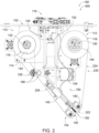
- Fig. 2 is a side view of liquid applicator 400
- Fig. 3 is another side view showing the opposite side of liquid applicator 400 to that shown in Fig. 2 .
- liquid applicator 400 includes pressure modulator 142 that operatively couples applicator head 104 to frame 102.
- Liquid applicator 400 also includes a robotic arm coupling mechanism 178 coupled to frame 102 in a position opposite to that of applicator head 104.
- Robotic arm coupling mechanism 178 is configured to interconnect liquid applicator 400 with a robotic arm 20 and support liquid applicator 400 relative to robotic arm 20.
- robotic arm coupling mechanism 178 is configured to selectively couple to and disconnect liquid applicator 400 from robotic arm 20, such that liquid applicator 400 may be selectively removed from robotic arm 20 for service and/or such that liquid applicator 400 may be selectively utilized as an end effector with a plurality of different robotic arms 20.
- robotic arm coupling mechanism 178 includes one or more power connections configured to supply power from one or more external power sources to liquid applicator 400 and/or one or more digital connections configured to transmit data signals between the various actuated components of liquid applicator 400 and controller 10.
- liquid applicator 400 is supporting applicator fabric 220 for operable application of liquid 200 to substrate 300.
- fabric conveyance system 110 is supporting deployed portion 224 of applicator fabric 220 with section 222 of applicator fabric 220 tensioned across fabric-contacting members 140 of applicator head 104.
- supply spool 116 of applicator fabric 220 is supported by fabric pay-out assembly 112.
- fabric pay-out assembly 112 comprises pay-out motor 130 that is engaged with, and configured to apply pay-out torque to, a drum 144 that supports supply spool 116.
- Fabric take-up assembly 114 includes a drum 144 supporting take-up spool 118 formed from applicator fabric 220 received from applicator head 104. Fabric take-up assembly 114 also includes take-up motor 132 engaged with drum 144 and configured to rotate drum 144 to spool up applicator fabric 220 received from applicator head 104. Fabric conveyance system 110 also includes pinch roller assembly 126, which includes rollers 168 engaged with take-up portion 226 of applicator fabric 220 and pinch roller assembly motor 170 configured to selectively rotate rollers 168 to move applicator fabric 220 from supply spool 116, across applicator head 104, and towards take-up spool 118.
- Fabric conveyance system 110 further includes radius detector 120 configured to detect the pay-out radius 122 of supply spool 116 and generate corresponding detector signals 12 that are received by controller 10. Controller 10 is configured to actuate pay-out motor 130 and take-up motor 132 based on the detector signals 12 received from radius detector 120, such as discussed herein.
- Liquid delivery system 150 of liquid applicator 400 includes liquid reservoir 152 for containing liquid 200, pump 154 configured to selectively flow liquid 200, and liquid outlet 156 positioned to apply liquid 200 to section 222 of applicator fabric 220.
- Liquid delivery system 150 further includes pump motor 158 configured to selectively actuate liquid pump 154 as discussed herein, and liquid conduits 172 that interconnect pump 154 with liquid reservoir 152 and liquid outlet 156.
- liquid applicator 400 also includes a power distribution unit 32 configured to route power to the actuated components of liquid applicator 400, and a communications unit 18 configured to route the detector signals 12 from radius detector 120 to controller 10, and route command signals 14 from controller 10 to the actuated components of liquid applicator 400.
- controller 10 and power sources 30 are external to, or remote from, frame 102 and the components of liquid applicator 400 coupled thereto.
- power distribution unit 32 is configured to receive, and distribute power from, the remote power sources 30, and communications unit 18 is configured to transmit the data signals between the remote controller 10 and the components of liquid applicator 400 that are operably coupled to frame 102.
- Fig. 4 is a partial isometric view of liquid applicator 400 showing applicator head 104, liquid outlet 156, and pressure modulator 142.
- Applicator fabric 220 is removed from the illustration of Fig. 4 for clarity.
- applicator head 104 includes a chassis 180 operably coupled to pressure modulator 142 and supporting fabric-contacting members 140.
- fabric-contacting members 140 include a pair of contact rollers 182 that are rotatably coupled to chassis 180, with chassis 180 supporting contact rollers 182 to extend parallel to and spaced apart from one another.
- Liquid delivery system 150 includes liquid distribution bar 162, which is operably coupled to chassis 180 to extend parallel to and between fabric-contacting members 140.
- Pressure modulator 142 includes a pair of rods 184 that are operably coupled to chassis 180 and received in a pneumatic cylinder assembly 186 that is configured to permit selective displacement of rods 184, together with applicator head 104, relative to frame 102.
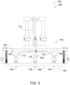
- Fig. 5 is a partial frontal view of liquid applicator 400 showing applicator head 104 and liquid distribution bar 162. Applicator fabric 220 and one of the contact rollers 182 are removed from the illustration of Fig. 5 for purposes of clarity.
- liquid distribution bar 162 includes a plurality of liquid ports 164 that are in fluid communication with liquid conduit 172 and configured to supply liquid 200 from liquid conduit 172 to section 222 of applicator fabric 220.
- each liquid port 164 includes a bore 163 that extends through a base surface 188 of liquid distribution bar 162.
- Liquid distribution bar 162 is positioned such that base surface 188 is in close proximity to, or contacts, the rear side of section 222 of applicator fabric 220. In this way, each liquid port 164 may deliver liquid 200 directly to the rear side of section 222 of applicator fabric 220.
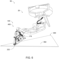
- automated liquid applicator assembly 50 that includes liquid applicator 400.
- automated liquid applicator assembly 50 includes a robotic arm 20 that is operably coupled to liquid applicator 400 through robotic arm coupling mechanism 178.
- robotic arm 20 is supporting and positioning liquid applicator 400 for operable application of liquid 200 to substrate 300. More specifically, robotic arm 20 is orienting liquid applicator 400 such that section 222 of applicator fabric 220 is parallel to and in contact with the surface 302 of substrate 300.
- robotic arm 20 is orienting liquid applicator 400 such that section 222 of applicator fabric 220 is parallel to and in contact with the surface 302 of substrate 300.
- robotic arm 20 is configured to move liquid applicator 400 across substrate 300, such as while maintaining section 222 of applicator fabric 220 in contact with surface 302 of substrate 300.
- Robotic arm 20 may be configured to move liquid applicator 400 in any suitable manner, such as within at least three degrees of freedom.
- Fig. 7 provides a flowchart that represents illustrative, non-exclusive examples of methods 500 for applying a liquid to a substrate with a liquid applicator according to the present disclosure.
- some steps are illustrated in dashed boxes indicating that such steps may be optional or may correspond to an optional version of methods 500 according to the present disclosure. That said, not all methods 500 according to the present disclosure are required to include each of the steps illustrated in solid boxes.
- the methods and steps illustrated in Fig. 7 are not limiting, and other methods and steps are within the scope of the present disclosure, including methods having greater than or fewer than the number of steps illustrated, as understood from the discussions herein.
- Methods 500 may be performed to apply a liquid 200 to a substrate 300. Methods 500 may be performed utilizing liquid applicator 100, liquid applicator 400, and/or automated liquid applicator assemblies 50 that are illustrated and discussed herein with reference to Figs. 1-6 .
- liquid applicators 100, and automated liquid applicator assemblies 50 discussed herein with reference to Fig. 7 and methods 500 may incorporate any of the features, functions, components, etc., as well as variants thereof, as those discussed herein with reference to Figs. 1-6 without requiring the inclusion of all such features, functions, components, etc.
- liquid applicator 100, liquid applicator 400, and/or automated liquid applicator assemblies 50 discussed herein with reference to Figs. 1-6 may incorporate any of the features, functions, components, etc., as well as variants thereof, as those discussed herein with reference to Fig. 7 and methods 500 without requiring the inclusion of all such features, functions, components, etc.
- controller 10 as discussed above, is programmed to perform or otherwise facilitate or implement one or more of the methods and/or steps represented in Fig. 7 and/or discussed herein.
- instructions for performing the various steps and/or methods described herein are stored as computer-readable instructions in non-transitory memory of controller 10.
- a processor of controller 10 is configured to execute the computer-readable instructions to perform the one or more steps and/or methods represented in Fig. 7 .
- methods 500 include delivering a liquid 200 to a section 222 of an applicator fabric 220 at 505, engaging the section 222 of the applicator fabric 220 with a substrate 300 at 520, and moving the section 222 of the applicator fabric 220 across the substrate 300 at 525.
- the delivering at 505 includes drawing the liquid 200 from a liquid reservoir at 510 and/or flowing the liquid 200 through a liquid outlet at 515.
- Methods 500 further may include maintaining tension in the applicator fabric 220 at 530, conveying the applicator fabric 220 across an applicator head 104 at 545, and/or repeating at 560.
- the maintaining at 530 includes detecting a pay-out radius of a supply spool 116 of the applicator fabric at 535 and/or adjusting a pay-out torque applied to the supply spool 116 of the applicator fabric 220 at 540.
- the conveying at 545 includes supplying the applicator fabric 220 to the applicator head 104 at 550 and/or receiving the applicator fabric 220 from the applicator head 104 at 555.
- the delivering at 505 includes delivering the liquid 200 to the section 222 of applicator fabric 220 that is supported by an applicator head 104 of the liquid applicator 100.
- the delivering at 505 additionally or alternatively may be referred to as wetting the section 222 of applicator fabric 220.
- the delivering at 505 includes delivering any suitable liquid 200 to the section of applicator fabric 220, such as any of the example liquids 200 discussed herein.
- the delivering at 505 includes delivering or applying the liquid 200 to a rear side 238 of the section 222 of applicator fabric 220, as discussed herein.
- the delivering at 505 includes drawing, pulling, or flowing the liquid 200 from a liquid reservoir 152 of the liquid applicator 100 that contains the liquid 200 at 510, such as discussed herein. Additionally or alternatively, in some examples, the delivering at 505 comprises flowing the liquid 200 through a liquid outlet 156 of the liquid applicator 100 that is positioned for operable application of the liquid 200 to the section 222 of applicator fabric at 515, such as discussed herein.
- the flowing at 515 comprises flowing the liquid 200 at an ambient pressure, such as discussed herein. More specifically, in some examples, the flowing at 515 comprises flowing the liquid 200 to the section 222 of applicator fabric 220 without increasing the pressure of, spraying, atomizing, and/or volatilizing the liquid 200.
- the liquid applicator 100 includes a liquid distribution bar 162 having a plurality of liquid ports 164 that collectively define the liquid outlet 156. In some such examples, the flowing at 515 comprises flowing the liquid 200 through the plurality of liquid ports 164 to the section 222 of applicator fabric 220. In some examples, the flowing at 515 is performed with the liquid applicator 100 oriented such that the section 222 of applicator fabric 220 extends horizontally or perpendicular relative to the direction of gravity.
- the drawing at 510 comprises drawing the liquid 200 with a pump 154 of the liquid applicator 100 and the flowing at 515 comprises flowing the liquid 200 with the pump 154 as discussed herein.
- the pump 154 comprises a rotor 166 that is configured to rotate to draw the liquid 200 from the liquid reservoir 152 and flow the liquid 200 through the liquid outlet 156.
- the drawing at 510 comprises rotating, with a pump motor 158 of the liquid applicator 100, the rotor 166 to draw the liquid 200 from the liquid reservoir 152 and/or the flowing at 515 comprises rotating, with the pump motor 158, the rotor 166 to flow the liquid 200 through the liquid outlet 156 and to the section 222 of applicator fabric 220.
- the drawing at 510 and the flowing at 515 are performed simultaneously or at least substantially simultaneously with one another.
- the delivering at 505 comprises delivering a predetermined volume of the liquid 200 to the section 222 of the applicator fabric 220.
- the predetermined volume of the liquid 200 is selected based upon an amount of liquid 200 that is required to adequately wet and/or saturate the section 222 of applicator fabric 220.
- the drawing at 510 comprises drawing the predetermined volume of liquid 200 from the liquid reservoir 152, and the flowing at 515 comprises flowing the predetermined volume of liquid 200 through the liquid outlet 156.
- the delivering at 505 comprises rotating, with the pump motor 158, the rotor 166 of the pump 154 through a predetermined degree of rotation to draw the predetermined volume of liquid 200 from the liquid reservoir 152 and flow the predetermined volume of liquid 200 through the liquid outlet 156.
- the predetermined degree of rotation may include a portion of a full rotation, such as at least 45 degrees (°), at least 90°, at least 180°, at least 270°, at most 360° and/or any suitable number of full rotations.
- the delivering at 505 may be performed with any suitable sequence or timing within methods 500 such as prior to engaging at 520, prior to moving at 525, prior to conveying at 545, and/or prior to, or least simultaneously/substantially simultaneously with, maintaining at 530.
- methods 500 include engaging, with the applicator head 104, the section 222 of applicator fabric 220 with the substrate 300 at 520.
- the engaging at 520 includes positioning the applicator head 104 in operable contact with the substrate 300 via the section 222 of applicator fabric 220.
- the liquid applicator 100 is operably coupled to a robotic arm 20 that is configured to move the liquid applicator 100 relative to the substrate 300.
- the engaging at 520 comprises moving the liquid applicator 100 with the robotic arm 20 to place section 222 of applicator fabric 220 supported by applicator head 104 in contact with the substrate 300.
- the engaging at 520 includes aligning the section 222 of applicator fabric 220 with a surface 302 defined by the substrate 300 such that at least a substantial portion of the section 222 of applicator fabric 220 directly contacts the surface 302 defined by the substrate 300.
- the surface 302 defined by the substrate 300 may be oriented at any suitable angle relative to the direction of gravity.
- the engaging at 520 comprises orienting the section 222 of applicator fabric 220 to a corresponding angle relative to the direction of gravity.
- the engaging at 520 may be performed with any suitable sequence or timing within methods 500, such as subsequent to the delivering at 505, prior to moving at 525, at least simultaneously/substantially simultaneously with maintaining at 530, and/or prior to conveying at 545.
- methods 500 further include moving the section 222 of applicator fabric 220 across a region of the substrate 300 at 525.
- the moving at 525 includes delivering the liquid 200 to the region of the substrate 300.
- the moving at 525 includes transferring at least a portion of the liquid 200 delivered to the section 222 of applicator fabric 220 during the delivering at 505 from the section 222 to the region of the substrate 300.
- the moving at 525 comprises spreading, wiping, and/or distributing the liquid 200 across a surface 302 defined by the substrate 300 with the section 222 of applicator fabric 220.
- the region of the substrate 300 may include a portion of, or the entirety of, the surface 302 defined by the substrate 300.
- the moving at 525 comprises forming an even, uniform, and/or thin layer of liquid 200 on the region of the substrate 300.
- the moving at 525 comprises moving the liquid applicator 100 across or relative to the substrate 300 with the robotic arm 20, such as discussed herein. Additionally or alternatively, in some examples, the moving at 525 includes supporting the liquid applicator 100, and correspondingly the section 222 of applicator fabric 220, in a stationary position and moving the substrate 300 relative to the section 222 of applicator fabric 220 such that the section 222 is moved across the region of the substrate 300.
- the moving at 525 includes removing material from the region of the substrate 300. More specifically, the moving at 525 may include transferring surface material (e.g., liquids and/or particulate) from the region of the substrate 300 to the section 222 of applicator fabric 220, such as by adhering, adsorbing, and/or absorbing the material to the section 222 of applicator fabric 220 and/or by dissolving the material into the liquid 200 contained in the section 222 of applicator fabric 220.
- surface material e.g., liquids and/or particulate
- the moving at 525 comprises moving the liquid applicator 100 in a predefined motion to move the section 222 of applicator fabric 220 across a corresponding region of the substrate 300. In some examples, the moving at 525 comprises moving the liquid applicator 100 in a linear motion to move the section 222 of applicator fabric 220 across a linear region of the substrate 300. Additionally or alternatively, in some examples, the moving at 525 comprises moving the liquid applicator 100 in a non-linear motion such as an orbital motion, and/or a reciprocating linear motion.
- the moving at 525 is performed with any suitable sequence or timing within methods 500, such as subsequent to the delivering at 505, subsequent to the engaging at 520, simultaneously or at least substantially simultaneously with maintaining at 530, and/or prior to conveying at 545.
- methods 500 include maintaining tension in a deployed portion 224 of the applicator fabric 220 at 530.
- the maintaining at 530 includes maintaining section tension in the section 222 of the applicator fabric 220 within a target section tension range.
- liquid applicator 100 includes a fabric pay-out assembly 112 configured to supply the applicator fabric 220 to the applicator head 104 from a supply spool 116 of the applicator fabric 220 and a fabric take-up assembly 114 configured to receive the applicator fabric 220 from the applicator head 104 and form a take-up spool 118 therefrom.
- the maintaining at 530 includes applying, with a pay-out torque adjuster 124 of the liquid applicator 100, a pay-out torque to the supply spool 116 to maintain the section tension in the section 222 of applicator fabric 220 within the target section tension range.
- the maintaining at 530 includes applying, with the pay-out torque adjuster 124, an upstream force to the deployed portion 224 of applicator fabric 220, such as discussed herein.
- the liquid applicator 100 includes a pinch roller assembly 126 configured to engage a take-up portion 226 of the applicator fabric 220.
- the maintaining at 530 includes engaging, with the pinch roller assembly 126, the take-up portion 226 of the applicator fabric 220.
- the maintaining section tension in the section 222 of applicator fabric 220 includes applying, with a pinch roller assembly 126 of the liquid applicator 100, a downstream force to the take-up portion 226 of the applicator fabric 220 to balance the upstream force applied to the deployed portion 224 of applicator fabric 220 by the pay-out torque adjuster 124, such as discussed herein.
- the engaging the take-up portion 226 of applicator fabric 220 includes selectively retaining, with the pinch roller assembly 126, the take-up portion of the applicator fabric 220 to restrict movement of the applicator fabric 220 relative to the applicator head 104, such as during the engaging at 520 and/or the moving at 525.
- the maintaining at 530 includes restricting the applicator fabric 220 from moving relative to the applicator head 104 such as in response to forces applied to the section 222 of the applicator fabric 220 during the engaging at 520 and/or the moving at 525.
- the maintaining at 530 includes detecting, with a radius detector 120 of the liquid applicator 100, a pay-out radius 122 of the supply spool 116 at 535, and adjusting, with the pay-out torque adjuster 124, the pay-out torque applied to the supply spool 116 based on the pay-out radius at 540.
- the adjusting at 540 includes decreasing the pay-out torque applied to the supply spool 116 in proportion to the pay-out radius 122. Stated differently, in some examples, the adjusting at 540 includes varying the pay-out torque applied to the supply spool 116 linearly with the pay-out radius 122 of the supply spool 116.
- the maintaining at 530 includes utilizing equations (1)-(4) discussed herein to determine, based on the detector signal 12, the amount of pay-out torque to apply to the supply spool 116 to maintain the section tension in the section 222 of applicator fabric 220 within the target section tension range.
- the maintaining at 530 includes maintaining the upstream force applied to the deployed portion 224 of applicator fabric 220 by the pay-out torque adjuster 124 as the pay-out radius 122 of the supply spool 116 decreases.
- the maintaining at 530 includes maintaining tension within one or more other sections of the deployed portion 224 of applicator fabric 220 within one or more respective target tension ranges.
- the maintaining at 530 may include maintaining a take-up tension in a downstream take-up portion 232 of the applicator fabric 220 that extends between the pinch roller assembly 126 and the take-up spool 118 within a target take-up tension range.
- the maintaining at 530 includes applying, with a take-up torque adjuster 128 of the liquid applicator 100, a take-up torque to the take-up spool 118 of applicator fabric 220 to maintain the take-up tension within the target take-up tension range.
- the maintaining at 530 includes applying, with the take-up torque adjuster, a downstream force to the downstream take-up portion 232 of applicator fabric 220, such as discussed herein.
- the maintaining the take-up tension in the downstream take-up portion of the applicator fabric is performed without moving or pulling the applicator fabric 220 through the pinch roller assembly 126 with the take-up torque adjuster.
- the maintaining comprises applying a smaller amount of take-up tension to the downstream take-up portion 232 of applicator fabric 220 than the section tension that is applied to the section 222 of the applicator fabric 220.
- the maintaining at 530 includes adjusting the take-up torque applied to the take-up spool 118 by the take-up torque adjuster 128 based on the pay-out radius 122 determined during the detecting at 535.
- the take-up spool 118 receives applicator fabric 220 that is supplied from the supply spool 116.
- the length of applicator fabric 220 on the take-up spool 118, and thereby a take-up radius 123 of the take-up spool 118 increases as the length of applicator fabric 220 on the supply spool 116, and thus the pay-out radius 122, decreases.
- the maintaining at 530 includes increasing the take-up torque applied to the take-up spool 118 by the take-up torque adjuster 128 as the pay-out radius 122 decreases.
- the maintaining at 530 is performed with any suitable sequence or timing within methods 500.
- the maintaining at 530 may be performed prior to, or simultaneously/at least substantially simultaneously with, the delivering at 505, the engaging at 520, the moving at 525, and/or conveying at 545.
- methods 500 include conveying the applicator fabric 220 across the applicator head 104 at 545.
- the conveying at 545 additionally or alternatively may be referred to herein as replenishing the section 222 of applicator fabric 220.
- the section 222 of applicator fabric 220 becomes soiled, and/or inundated with material absorbed from, and/or otherwise transferred from the substrate 300 during the engaging at 520 and the moving at 525.
- the conveying at 545 may include removing a soiled section 222 of applicator fabric 220 from the applicator head 104 and providing a new section 222 of applicator fabric 220 to the applicator head 104.
- the conveying at 545 includes supplying the applicator fabric 220 to the applicator head 104 at 550 and/or receiving the applicator fabric 220 from the applicator head at 555. More specifically, the supplying at 550 includes supplying the applicator fabric 220 from the fabric pay-out assembly 112 or from the supply spool 116 thereof. The receiving at 555 includes receiving, with the fabric take-up assembly 114, the applicator fabric 220 from the applicator head 104 and forming the take-up spool 118 of applicator fabric 220 therefrom.
- the supplying at 550 comprises rotating the supply spool 116. More specifically, in some examples, the supplying at 550 includes rotating the supply spool 116 by conveying the applicator fabric 220 in a downstream direction 228 with the pinch roller assembly 126, such as discussed herein.
- the receiving at 555 comprises rotating the take-up spool 118. More specifically, as discussed herein, in some examples the liquid applicator 100 includes a take-up motor 132 configured to selectively rotate the take-up spool 118. In some such examples, the receiving at 555 comprises rotating the take-up spool 118 with the take-up motor 132 to receive applicator fabric 220 thereon. In some examples, the receiving at 555 includes conveying, with the pinch roller assembly 126, the applicator fabric 220 from the applicator head 104 towards take-up spool 118 or in the downstream direction 228.
- the conveying at 545 includes conveying a preselected length of applicator fabric 220 across the applicator head 104, such as any of the preselected lengths of applicator fabric 220 discussed herein.
- the conveying at 545 includes moving, with the pinch roller assembly 126, the preselected length of applicator fabric 220 in the downstream direction 228 to move the preselected length of applicator fabric 220 across the applicator head 104 and/or draw the preselected length of applicator fabric 220 from the supply spool 116.
- the receiving at 555 includes rotating the take-up spool 118 to receive the preselected length of applicator fabric 220 from the pinch roller assembly 126.
- the conveying at 545 is performed with any suitable sequence or timing within methods 500, such as subsequent to the delivering at 505, subsequent to the engaging at 520, and/or subsequent to the moving at 525. Additionally or alternatively, the conveying at 545 is performed subsequent to, or simultaneously/at least substantially simultaneously with, the maintaining at 530. Stated differently, in some examples, methods 500 include maintaining tension in the applicator fabric 220 while conveying the applicator fabric 220 across the applicator head 104, such as discussed herein.
- methods 500 include repeating at 560.
- the repeating at 560 includes repeating any of the one or more steps of methods 500 in any suitable order.
- the repeating at 560 may include repeating a given step of methods 500 in a similar manner, or an at least substantially similar manner, to that which the given step was previously performed in methods 500.
- the repeating at 560 may include repeating a given step in a different manner from that which the given step was previously performed in methods 500.
- the repeating at 560 is performed to apply the liquid 200 across a plurality of regions of the substrate 300, and/or such as to cover the entire substrate 300 with liquid 200 by repeating methods 500 any suitable number of times.
- the delivering at 505, the engaging at 520, and the moving at 525 are performed to apply liquid 200 to a first region of the substrate 300
- the conveying at 545 comprises replenishing the section 222 of applicator fabric 220 subsequent the engaging at 520 and the moving at 525
- the repeating at 560 includes repeating the delivering at 505, the engaging at 520, and the moving at 525, to apply the liquid 200 to a second region of the substrate 300.
- the repeating at 560 further includes repeating the conveying at 545 to replenish the section 222 of applicator fabric 220 after the liquid 200 is applied to the second region of the substrate 300.
- methods 500 include applying liquid 200 to a plurality of different substrates 300.
- methods include performing the delivering at 505, the engaging at 520, and the moving at 525 to apply the liquid 200 to a first substrate 300, and optionally subsequently performing the conveying at 545 to replenish the section 222 of applicator fabric 220, and the repeating at 560 includes repeating the delivering at 505, the engaging at 520, and the moving at 525 to apply the liquid 200 to a second substrate 300.
- the repeating at 560 also may be performed any suitable number of times to apply liquid 200 to any suitable number of regions of the substrate 300 and/or to any suitable number of substrates 300.
- the delivering at 505, the engaging at 520, and the moving at 525 are performed to apply a first liquid 200 to the substrate 300 and the repeating at 560 includes applying a second liquid 200 to the substrate 300 that is different from the first liquid 200.
- the delivering at 505, the engaging at 520, and the moving at 525 may be performed to clean, or remove the mold release agent from, the substrate 300, and the repeating at 560 may be performed to apply a second liquid 200 to the substrate 300, such as a mold release agent, a paint, a resin, and/or an adhesive.
- liquid applicators 100 include a plurality of liquid delivery systems 150, each including, and being configured to deliver, a different liquid 200 to the section 222 of applicator fabric 220.
- the delivering at 505 includes delivering a first liquid 200 from the first liquid delivery system 150, and then during the repeating at 560, the delivering at 505 includes delivering a second liquid 200 from a second liquid delivery system 150.
- a controller 10 may be any suitable device or devices that are configured to perform the functions of the controller discussed herein.
- the controller may include one or more of an electronic controller, a dedicated controller, a special-purpose controller, a personal computer, a special-purpose computer, a display device, a logic device, a memory device, and/or a memory device having computer readable media suitable for storing computer-executable instructions for implementing aspects of systems and/or methods according to the present disclosure.
- At least substantially when modifying a degree or relationship, includes not only the recited “substantial” degree or relationship, but also the full extent of the recited degree or relationship. A substantial amount of a recited degree or relationship may include at least 75% of the recited degree or relationship.
Landscapes
- Engineering & Computer Science (AREA)
- Mechanical Engineering (AREA)
- Treatment Of Fiber Materials (AREA)
Abstract
Description
- The present disclosure relates to liquid applicators and methods of applying liquid to a substrate.
- The application of a liquid across a substrate is an essential process in many industrial applications including the manufacture, maintenance, and upkeep of structures and components. As an example, during the manufacture of composite parts, a liquid mold release agent typically is applied across the surface of a mold or lay-up mandrel before a composite part is formed thereon. After the composite part is cured and removed from the mold, the mold typically is cleaned with a solvent or cleaning solution to remove the liquid mold-release agent and any remnants from forming the composite part before a new coating of the liquid mold release agent is applied to the mold for forming another composite part. In this example, and in many other industrial applications, it is often important for the liquid to be applied in a uniform or precise manner such that the liquid-treated surface is provided with a consistent finish.
- In the past, this process often is carried out manually, with an operator using a cloth or fabric to apply and wipe the liquid across the substrate. Among other drawbacks, manual application can suffer from inconsistency and present ergonomic restrictions particularly with large surface areas. Additionally, many conventional processes spray, jet, or shower the liquid during the application, which can facilitate volatilization of the liquid and thereby place additional design requirements on the system to manage the volatilized liquid load. Thus, a need exists for improved methods and devices for applying liquid to a substrate, which may enhance the uniformity of the liquid application and/or reduce volatilization of the liquid during the application process.
- Liquid applicators and methods of applying a liquid to a substrate are disclosed herein. The liquid applicators include a frame and an applicator head operably coupled to the frame and configured to support a section of an applicator fabric for operable application of the liquid to the substrate. The liquid applicators further include a fabric conveyance system operably coupled to the frame and configured to selectively move the applicator fabric across the applicator head. The fabric conveyance system includes a fabric pay-out assembly configured to supply the applicator fabric to the applicator head and a fabric take-up assembly configured to receive the applicator fabric from the applicator head. The liquid applicators further include a liquid delivery system configured to deliver the liquid to the section of the applicator fabric. In some examples, the fabric pay-out assembly is configured to supply the applicator fabric from a supply spool, and the liquid applicator further includes a radius detector configured to detect a radius of the supply spool, a pay-out torque adjuster configured to apply a pay-out torque to the supply spool, and a controller configured to selectively vary the pay-out torque applied by the pay-out torque adjuster based on a pay-out radius. In some examples, the liquid delivery system includes a liquid outlet positioned to supply the liquid directly to the section of the applicator fabric, a liquid reservoir configured to contain the liquid, and a pump configured to selectively draw the liquid from the liquid reservoir and flow the liquid through the liquid outlet at an ambient pressure.
- The methods include delivering the liquid to the section of applicator fabric, engaging the section of applicator fabric with the substrate, and moving the section of the applicator fabric across the substrate to apply the liquid thereto. In some examples, the methods further include detecting a pay-out radius of the supply spool and adjusting the pay-out torque applied to the supply spool based on the pay-out radius. Additionally or alternatively, in some examples, the methods further include drawing the liquid from the liquid reservoir, and flowing the liquid through the liquid outlet to the section of applicator fabric at an ambient pressure.
-
-
Fig. 1 is a schematic representation of liquid applicators according to the present disclosure. -
Fig. 2 is a side view illustrating an example liquid applicator according to the present disclosure. -
Fig. 3 is another side view of the example liquid applicator ofFig. 2 . -
Fig. 4 is a partial isometric view showing a portion of the example liquid applicator ofFig. 2 . -
Fig. 5 is a head-on view showing a portion of the example liquid applicator ofFig. 2 . -
Fig. 6 is an isometric view showing an example automated liquid applicator assembly that includes the example liquid applicator ofFig. 2 . -
Fig. 7 is a flowchart schematically representing examples of methods according to the present disclosure. -
Figs. 1-7 provide examples ofliquid applicators 100, automatedliquid applicator assemblies 50 includingliquid applicators 100, andmethods 500 for applying liquid to a substrate according to the present disclosure. Elements that serve a similar, or at least substantially similar, purpose are labeled with like numbers in each ofFigs. 1-7 and these elements may not be discussed in detail herein with reference to each ofFigs. 1-7 . Similarly, all elements may not be labeled in each ofFigs. 1-7 , but reference numerals associated therewith may be utilized herein for consistency. Elements, components, and/or features that are discussed herein with reference to one or more ofFigs. 1-7 may be included in and/or utilized with any ofFigs. 1-7 without departing from the scope of the present disclosure. - Generally, in the figures, elements that are likely to be included in a given example are illustrated in solid lines, while elements that are optional to a given example are illustrated in dashed lines. However, elements that are illustrated in solid lines are not essential to all examples of the present disclosure, and an element shown in solid lines may be omitted from a particular example without departing from the scope of the present disclosure. In
Fig. 1 , dot-dash lines may be utilized to indicate materials utilized by, but not necessarily included in,liquid applicator 100, includingliquid 200 andapplicator fabric 220. Additionally, electrical and/or information communication connections may be indicated in dotted lines inFig. 1 . -
Fig. 1 is a schematic representation showing examples ofliquid applicators 100 according to the present disclosure. As shown inFig. 1 ,liquid applicators 100 are configured to apply aliquid 200 to asubstrate 300 via anapplicator fabric 220.Liquid applicators 100 include aframe 102 configured to support the various components ofliquid applicator 100 in relation to one another, and anapplicator head 104 operably coupled to theframe 102.Applicator head 104 is configured to support asection 222 of theapplicator fabric 220 for operable application ofliquid 200 tosubstrate 300.Liquid applicators 100 also include afabric conveyance system 110 operably coupled toframe 102 and configured to selectively moveapplicator fabric 220 acrossapplicator head 104. More specifically,fabric conveyance system 110 includes a fabric pay-out assembly 112 configured to supply theapplicator fabric 220 toapplicator head 104 and a fabric take-up assembly 114 configured to receiveapplicator fabric 220 fromapplicator head 104.Liquid applicators 100 further include aliquid delivery system 150 configured to selectively deliver theliquid 200 to thesection 222 of theapplicator fabric 220. - In some examples,
liquid applicators 100 further include acontroller 10 configured to actuate various components ofliquid applicator 100 as discussed in more detail herein. In some examples,controller 10 is configured to receive sensor signals from one or more sensors included inliquid applicators 100 and actuate one or more components ofliquid applicator 100 based upon the sensor signals. More specifically, as shown inFig. 1 , when included,controller 10 is in communication, such as digital and/or electrical communication with various actuated components ofliquid applicator 100, and is configured to selectivelyissue command signals 14 to the various actuated components to control operation thereof. For brevity, in some instances,command signals 14 and sensor signals are generally, or collectively, referred to herein as data signals. - In some examples,
liquid applicators 100 are included in, or define a portion of, an automatedliquid applicator assembly 50 that is configured to selectively applyliquid 200 tosubstrate 300. In some such examples,liquid applicator 100 is configured as an end effector of automatedliquid applicator assembly 50. More specifically, automatedliquid applicator assembly 50 may include arobotic arm 20 that is configured to moveliquid applicator 100 relative tosubstrate 300, andliquid applicator 100 is, or is configured to be, operably coupled torobotic arm 20 to form an end effector thereof. For examples in whichliquid applicator 100 is included in automatedliquid applicator assembly 50,controller 10 may be included in automatedliquid applicator assembly 50, and optionally remote fromframe 102 and the components ofliquid applicator 100 operatively coupled thereto. In some examples,controller 10 also is configured to operaterobotic arm 20 such as to move, orient, and positionliquid applicator 100 relative tosubstrate 300 as discussed herein. Additionally or alternatively, in some examples, automatedliquid applicator assembly 50 includes a plurality ofcontrollers 10, at least one of which being configured to operate the components ofliquid applicator 100 and anothercontroller 10 being configured to operaterobotic arm 20. -
Liquid applicators 100 may be described as being configured to wet, saturate, load, soak, impregnate, and/or otherwisedose section 222 ofapplicator fabric 220 withliquid 200 and applyliquid 200 tosubstrate 300 by engaging theliquid 200 wetted, saturated, loaded, soaked, and/or impregnatedsection 222 ofapplicator fabric 220 withsubstrate 300. In some examples,liquid applicators 100 are configured to applyliquid 200 across a region or area ofsubstrate 300 by engaging thewetted section 222 ofapplicator fabric 220 withsubstrate 300 whilesection 222 is moved or wiped across the area or region ofsubstrate 300. In the present disclosure,section 222 ofapplicator fabric 220 may be referred to as wettedsection 222 or liquid-wettedsection 222 whensection 222 is wetted, saturated, loaded, soaked, impregnated, and/or otherwise dosed withliquid 200. - As discussed herein,
section 222 ofapplicator fabric 220 may include the portion ofapplicator fabric 220 that is directly supported byapplicator head 104. As shown inFig. 1 ,liquid applicators 100 are configured to support a deployedportion 224 ofapplicator fabric 220 that extends from fabric pay-out assembly 112, acrossapplicator head 104, and to fabric take-up assembly 114. In some examples,fabric conveyance system 110 is configured totension applicator fabric 220 acrossapplicator head 104 such thatapplicator head 104 defines the shape, geometry, and/or orientation ofsection 222. In some examples,applicator head 104 includes a fabric-contacting region that is configured to directly contact and supportsection 222 ofapplicator fabric 220. In some such examples,applicator head 104 includes a pair of fabric-contactingmembers 140 each being configured to directly contact and supportsection 222 ofapplicator fabric 220. - In some examples, fabric-contacting
members 140 are positioned to extend parallel to (or at least substantially parallel to) and laterally spaced apart from one another such thatfabric conveyance system 110tensions section 222 ofapplicator fabric 220 to extend across and between the pair of fabric-contactingmembers 140. In this way, fabric-contactingmembers 140 may supportsection 222 ofapplicator fabric 220 such thatsection 222 forms a sheet for operable application ofliquid 200 tosubstrate 300. In some examples, each fabric-contactingmember 140 is oriented such that a length of the fabric-contactingmember 140 is parallel to a width of thesection 222 ofapplicator fabric 220. As defined herein, the width ofsection 222 refers to the dimension ofapplicator fabric 220 that is transverse to the length of deployedportion 224. More specific examples of suitable fabric-contactingmembers 140 include contact rollers, elongate bladders, and/or elongate pneumatic bags. For some examples in which fabric- contactingmembers 140 include contact rollers, the contact rollers are oriented such that the axis of rotation of each contact roller is at aligned or least substantially aligned with the width ofsection 222. -
Applicator head 104 is configured to engagesection 222 ofapplicator fabric 220 withsubstrate 300. As shown inFig. 1 , in some examples,liquid applicators 100 include apressure modulator 142 that operably couplesapplicator head 104 to frame 102 andpositions applicator head 104 relative to frame 102.Pressure modulator 142 additionally or alternatively may be referred to as a counter balance and/or a force controller. When included,pressure modulator 142 is configured to maintain a pressure betweenapplicator head 104 andsubstrate 300 within a target pressure range whenapplicator head 104 is operably engaged withsubstrate 300. For example,pressure modulator 142 may be configured to permitapplicator head 104 to deflect relative to frame 102 whenapplicator head 104 is moved along asubstrate 300 that is non-planar and/or that includes topographical variations while maintaining the pressure therebetween within the target pressure range. In more specific examples,pressure modulator 142 includes a pneumatic piston assembly that is configured to modulate recoil force betweenapplicator head 104 andframe 102. -
Liquid applicators 100 are configured to apply liquid 200 to anysuitable substrate 300. As examples,substrate 300 may include a plastic material, a polymeric material, a ceramic, a composite material, such as a carbon fiber reinforced polymer, a partially constructed composite material, a metallic material, such as aluminum or an aluminum alloy, and/or combinations thereof. In some examples,substrate 300 is defined by, or included in a component, and/or an aerospace component. Examples of suitable aerospace components include a fuselage, a wing, a wing section, a winglet, a horizontal stabilizer, a vertical stabilizer, as well as subcomponents thereof and/or partially constructed structures thereof. Additionally or alternatively, in some examples,substrate 300 is included in or defined by a mold and/or mandrel for forming a component. Thus, whileFig. 1 illustratessubstrate 300 as defining asurface 302, which is planar,liquid applicator 100 may be configured to apply liquid 200 tosurfaces 302, which may be non-planar.Liquid applicators 100 also may be configured to apply liquid to asubstrate 300 that is in any suitable orientation relative to the direction of gravity. For example,liquid applicators 100 may be configured to apply liquid 200 to asubstrate 300 that is horizontal, vertical, inverted, and/or oriented at any suitable angle therebetween.Liquid applicators 100 also may be configured to apply liquid 200 to asubstrate 300 that is curved and/or that defines asurface 302 having a plurality of orientations relative to the direction of gravity. -
Liquid applicators 100 may be utilized to apply liquid 200 tosubstrate 300 for any suitable purpose. In some examples,liquid applicators 100 are configured to clean or remove material, such as surface particulate, fromsubstrate 300. In some examples,substrate 300 is included in or defined by a component that needs to be cleaned prior to cleaning, coating, or otherwise applying a material tosubstrate 300. In such examples, the material that is to be cleaned or removed fromsubstrate 300 is transferred tosection 222 ofapplicator fabric 220 whensection 222 is engaged with, and optionally moved across,substrate 300. In some examples,liquid applicators 100 are configured to apply a thin film ofliquid 200 tosubstrate 300, such thatliquid 200 evaporates or volatilizes subsequent to application tosubstrate 300. In some examples,liquid applicators 100 are configured to apply a low boiling point or volatile liquid tosubstrate 300. In some examples, liquid 200 is configured to facilitate transfer of the material fromsubstrate 300 to the wettedsection 222 ofapplicator fabric 220, such as by dissolving the material or wicking the material into the wettedsection 222. - Additionally or alternatively, in some examples,
liquid applicators 100 are configured to apply a liquid 200 tosubstrate 300 that is configured to remain onsubstrate 300 permanently or at least within an operational time frame. In a more specific example,liquid applicators 100 may be configured to apply a liquid 200 that is a mold release agent tosubstrate 300, such as a mold. Additionally or alternatively, in some examples,liquid applicators 100 are configured to apply a liquid 200 tosubstrate 300, such as a partially constructed component, that binds or otherwise adheres tosubstrate 300 subsequent to application byliquid applicator 100. In some such examples, liquid 200 includes a paint, a resin, an adhesive, a binder, a curing material, a polymeric material, and/or combinations thereof. - In many of the above applications, it is desirable for
liquid applicators 100 to apply a thin, even, uniform, and/or compositionally consistent layer or coating ofliquid 200 tosubstrate 300. With this in mind,liquid applicators 100 may be configured to support or providesection 222 ofapplicator fabric 220 in a manner thatsection 222 forms a uniform or consistent interface for applying liquid 200 tosubstrate 300. Thus, in some examples,fabric conveyance system 110 is configured to moveapplicator fabric 220 acrossapplicator head 104 between applications ofliquid 200 tosubstrate 300 to replenish or provideapplicator head 104 with a new orunsoiled section 222 ofapplicator fabric 220. In other words,fabric conveyance system 110 is configured to move asoiled section 222 ofapplicator fabric 220 that has applied liquid 200 to, and/or cleaned,substrate 300 fromapplicator head 104 and provide an unsoiled ornew section 222 ofapplicator fabric 220 toapplicator head 104 betweenliquid 200 applications. Additionally or alternatively, in some examples,fabric conveyance system 110 is configured to maintain tension insection 222 ofapplicator fabric 220 and/or restrictapplicator fabric 220 from moving relative toapplicator head 104 such thatsection 222 forms an even, uniform, and/or planar interface for applying liquid 200 tosubstrate 300. - As shown in
Fig. 1 , in some examples, fabric pay-outassembly 112 is configured to support asupply spool 116 ofapplicator fabric 220 and deliverapplicator fabric 220 fromsupply spool 116. Similarly, in some examples, fabric take-upassembly 114 is configured to form a take-upspool 118 of theapplicator fabric 220 received fromapplicator head 104 and support the take-upspool 118. In such examples, the deployedportion 224 ofapplicator fabric 220 extends fromsupply spool 116 acrossapplicator head 104 and to take-upspool 118. In some examples, fabric pay-outassembly 112 includes adrum 144 for supportingsupply spool 116 and/or fabric take-upassembly 114 includes adrum 144 for supporting take-upspool 118. - Stated another way, in some examples, fabric pay-out
assembly 112 is configured to moveapplicator fabric 220 fromsupply spool 116 to take-upspool 118. In this way, the radius ofsupply spool 116, which is referred to herein as a pay-outradius 122, decreases asfabric conveyance system 110 movesapplicator fabric 220 acrossapplicator head 104. Likewise, the radius of take-upspool 118, which is referred to herein as a take-upradius 123, increases asfabric conveyance system 110 movesapplicator fabric 220 acrossapplicator head 104. In some examples,fabric conveyance system 110 is configured to rotatesupply spool 116 to deliverapplicator fabric 220 therefrom and rotate take-upspool 118 to receiveapplicator fabric 220 thereon. Thus, as defined herein, pay-outradius 122 extends between the axis about which supplyspool 116 rotates and the outermost radial extent ofsupply spool 116, and take-upradius 123 extends between the axis about which take-upspool 118 rotates and the outermost radial extent of take-upspool 118. Whensupply spool 116 is supported by arespective drum 144, a portion of pay-outradius 122 is defined by therespective drum 144. Likewise, when take-upspool 118 is supported bydrum 144, a portion of take-upradius 123 is defined by therespective drum 144. - In some examples,
fabric conveyance system 110 is configured to maintain tension within deployedportion 224 ofapplicator fabric 220 such thatsection 222 ofapplicator fabric 220 is supported for operable application ofliquid 200 tosubstrate 300 and/or such thatapplicator fabric 220 is moved evenly betweensupply spool 116 and take-upspool 118. With this in mind, in some examples,liquid applicator 100 is configured to control a torque applied to supplyspool 116 and/or a torque applied to take-upspool 118 such that tension within deployedportion 224 ofapplicator fabric 220, or one ormore sections 222 thereof, is maintained within a desired target range. - As shown in
Fig. 1 , in some examples,fabric conveyance system 110 further includes aradius detector 120 configured to detect pay-outradius 122 ofsupply spool 116, and a pay-outtorque adjuster 124 configured to apply a pay-out torque to supplyspool 116. As mentioned, in some examples,liquid applicators 100 includecontroller 10. In some such examples,controller 10 is in communication withradius detector 120 and pay-outtorque adjuster 124. In some examples,controller 10 is configured to receive, fromradius detector 120, adetector signal 12 respective to (i.e., includes data corresponding to) pay-outradius 122 and to actuate pay-outtorque adjuster 124 based on thedetector signal 12 to maintain a section tension insection 222 ofapplicator fabric 220 within a target section tension range. -
Fabric conveyance system 110 may be described as being configured to selectively moveapplicator fabric 220 in adownstream direction 228 that extends along deployedportion 224 ofapplicator fabric 220 fromsupply spool 116 towards take-upspool 118. In some examples, pay-outtorque adjuster 124 is configured to apply the pay-out torque to supplyspool 116 in a direction that applies an upstream force to the deployedportion 224 ofapplicator fabric 220, in which the upstream force is in anupstream direction 230 that is opposed todownstream direction 228. Stated differently, in some examples,controller 10 is configured to actuate pay-outtorque adjuster 124 to apply tension to deployedportion 224 ofapplicator fabric 220 inupstream direction 230. -
Radius detector 120 may include any suitable sensor for detecting pay-outradius 122 ofsupply spool 116. Examples ofsuitable radius detectors 120 include a caliper, a displacement sensor, a sonic sensor, an optical length sensor, a laser sensor, and/or a laser triangulation sensor. In some examples,controller 10 is configured to selectively vary the pay-out torque applied to supplyspool 116 ofapplicator fabric 220 by pay-outtorque adjuster 124 in proportion to, or linearly with, pay-outradius 122. Stated differently, in such examples,controller 10 is configured to selectively decrease the pay-out torque applied to supplyspool 116 as pay-outradius 122 decreases. For some examples in whichradius detector 120 comprises a laser sensor,controller 10 utilizes equations (1)-(4) for determining a magnitude of pay-out torque to applysupply spool 116 based on a raw laser reading ordetector signal 12 received from radius detector 120:


portion 224applicator fabric 220, Rp is the pay-outradius 122, r is the radius of anempty supply spool 116, which is the radius ofdrum 144 whensupply spool 116 is supported ondrum 144, R is the maximum or full pay-outradius 122, L is the raw laser signal at R, I is the raw laser signal at r, and x is the actual laser reading. Thus, in such examples, there is a linear relationship between the change in laser output and the pay-out torque to be applied to supplyspool 116 to maintain the section tension insection 222 ofapplicator fabric 220 within the target section tension range. - Generally speaking, the target section tension range corresponds to a magnitude of torque that is adequate to render
section 222 with the desired application interface (e.g., a planar surface) and/or restrictapplicator fabric 220 from moving relative toapplicator head 104 without damagingapplicator fabric 220 and/or one or more components ofliquid applicator 100. Illustrative non-exclusive examples of the pay-out torque applied by pay-outtorque adjuster 124 include at least 0.1 Newton-meters (Nm), at least 0.15 Nm, at least 0.2 Nm, at least 0.3 Nm, at least 0.35 Nm, at least 0.4 Nm, at most 0.3 Nm, at most 0.35 Nm, at most 0.4 Nm, at most 0.45 Nm, at most 0.5 Nm, at most 0.55 Nm, at most 0.6 Nm, and/or at most 1 Nm. - As shown in
Fig. 1 , in some examples, fabric pay-outassembly 112 includes a pay-outmotor 130 that is, or includes, pay-outtorque adjuster 124. Examples of suitable pay-outmotors 130 include an electric motor, a rotary motor, a servomotor, and/or a smart motor. - With continued reference to
Fig. 1 , deployedportion 224 ofapplicator fabric 220 includes a take-upportion 226 that extends betweenapplicator head 104 and take-upspool 118. In some examples,fabric conveyance system 110 further includes apinch roller assembly 126 configured to engage take-upportion 226 ofapplicator fabric 220 and selectively convey take-upportion 226 towards take-upspool 118. In other words, when included,pinch roller assembly 126 is configured to selectively conveyapplicator fabric 220 indownstream direction 228. In some examples,pinch roller assembly 126 is configured to provide the motive force for movingapplicator fabric 220 acrossapplicator head 104 and/or for rotatingsupply spool 116 to provideapplicator fabric 220 toapplicator head 104. - In some examples,
controller 10 is in communication withpinch roller assembly 126 and configured to actuatepinch roller assembly 126 to apply motive force toapplicator fabric 220 and/or to selectively apply tension toapplicator fabric 220. As mentioned, in some examples,fabric conveyance system 110 is configured to restrict movement ofapplicator fabric 220 relative toapplicator head 104 during application ofliquid 200 tosubstrate 300 viasection 222 ofapplicator fabric 220. In some such examples,controller 10 is configured to actuatepinch roller assembly 126 to selectively retain take-upportion 226 ofapplicator fabric 220 against movement inupstream direction 230 when pay-outtorque adjuster 124 applies the upstream force to deployedportion 224 ofapplicator fabric 220. Stated differently, in some examples,controller 10 actuates pinchroller assembly 126 to apply tension to take-upportion 226 inupstream direction 230 that balances the tension applied to deployedportion 224 ofapplicator fabric 220 by pay-outtorque adjuster 124, such that deployedportion 224 ofapplicator fabric 220 is restricted from movement relative toapplicator head 104. Thus, when included,pinch roller assembly 126 is configured to maintain section tension insection 222 ofapplicator fabric 220 within the target section tension range together with pay-outtorque adjuster 124. - As shown in
Fig. 1 , in some examples,pinch roller assembly 126 includes a pair ofrollers 168 that are configured to engage with opposing sides of take-upportion 226 ofapplicator fabric 220 and pinch take-upportion 226 therebetween. In some examples,pinch roller assembly 126 further includes a pinchroller assembly motor 170 in communication withcontroller 10 and configured to selectively rotaterollers 168, such as responsive to command signals 14 received fromcontroller 10. Examples of suitable pinchroller assembly motors 170 include an electric motor, a rotary motor, a servomotor, and/or a smart motor. - With continued reference to
Fig. 1 , whenfabric conveyance system 110 includespinch roller assembly 126, deployedportion 224 ofapplicator fabric 220 includes a downstream take-upportion 232 that extends betweenpinch roller assembly 126 and take-upspool 118. In some examples,fabric conveyance system 110 further includes a take-uptorque adjuster 128 configured to apply a take-up torque to take-upspool 118 ofapplicator fabric 220. When included, take-uptorque adjuster 128 is in communication with and configured to receivecommand signals 14 fromcontroller 10. More specifically, in some examples,controller 10 is configured to actuate take-uptorque adjuster 128 based ondetector signals 12 fromradius detector 120 to maintain a take-up tension in downstream take-upportion 232 ofapplicator fabric 220 within a target take-up tension range. In other words,controller 10 may be configured to vary the take-up torque applied by take-uptorque adjuster 128 based on pay-outradius 122, which decreases as take-upradius 123 increases. Thus, in some examples,controller 10 is configured to actuate take-uptorque adjuster 128 to increase the take-up torque applied to take-upspool 118 as pay-outradius 122 ofsupply spool 116 decreases and/or as take-upradius 123 increases. - The target take-up tension range may be the same as, or different from, the target section tension range. In some examples, the target take-up tension range is less than the target section tension range. In some examples, take-up
torque adjuster 128 is configured to apply the take-up torque to take-upspool 118 in a direction that applies the downstream force to the downstream take-upportion 232 of theapplicator fabric 220. In some examples, take-uptorque adjuster 128 is configured to apply the take-up torque to the take-up spool in a magnitude that maintains the take-up tension within the take-up tension range without causing theapplicator fabric 220 to be pulled or slip throughpinch rollers 168. In other words, the downstream force applied to the downstream take-upportion 232 of theapplicator fabric 220 may not move theapplicator fabric 220 throughrollers 168 ofpinch roller assembly 126 whenrollers 168 are engaged with, or retaining, the take-upportion 226 ofapplicator fabric 220. Stated yet another way, the downstream force applied to the downstream take-upportion 232 ofapplicator fabric 220 may only apply the take-up tension to the downstream take-upportion 232 without increasing the section tension in thesection 222 of theapplicator fabric 220. In some examples, fabric take-upassembly 114 includes a take-upmotor 132 that is, or includes, take-uptorque adjuster 128. When included, take-upmotor 132 also is configured to selectively rotate take-upspool 118, such as responsive to control signals fromcontroller 10, to receiveapplicator fabric 220 onto take-upspool 118. Examples of suitable take-upmotors 132 include an electric motor, a rotary motor, a servomotor, and/or a smart motor. - In some examples,
pinch roller assembly 126 is configured to selectively move a preselected length ofapplicator fabric 220 acrossapplicator head 104 indownstream direction 228 during a fabric regeneration cycle. In some such examples,pinch roller assembly 126 also is configured to draw the preselected length of applicator fabric fromsupply spool 116 of applicator fabric. In some examples,controller 10 is configured to actuate take-upmotor 132 to rotate take-upspool 118 and receive the preselected length ofapplicator fabric 220 during the applicator fabric regeneration cycle. In some examples, the preselected length ofapplicator fabric 220 is a threshold fraction of the length ofsection 222 ofapplication fabric 220, with examples of the threshold fraction including at least 90%, at least 100%, at least 120%, at least 130%, at least 150%, at most 100%, at most 120%, at most 130%, at most 150%, and/or at most 200%. -
Fabric conveyance system 110 also may be configured to maintain section tension insection 222 ofapplicator fabric 220 within the target section tension range whilefabric conveyance system 110 movesapplicator fabric 220 acrossapplicator head 104 during an applicator fabric regeneration cycle. In such examples, pay-outtorque adjuster 124 and/or pay-outmotor 130 are configured to permit rotation ofsupply spool 116 during the applicator fabric regeneration cycle while applying the pay-out torque to supplyspool 116 in a direction that applies the upstream force to deployedportion 224 ofapplicator fabric 220. Similarly, in some examples,fabric conveyance system 110 is configured to maintain take-up tension in downstream take-upportion 232 ofapplicator fabric 220 during an applicator fabric regeneration cycle. For example, responsive to command signal(s) 14 from controller, take-upmotor 132 may rotate take-upspool 118 to receiveapplicator fabric 220 at the same linear rate aspinch roller assembly 126 movesapplicator fabric 220 towards take-upspool 118 while applying the take-up torque to take-upspool 118 to maintain the take-up tension in the downstream take-upportion 232 ofapplicator fabric 220 within the target take-up tension range. -
Liquid applicators 100 and/orfabric conveyance system 110 may be configured to handle or utilize any suitable type ofapplicator fabric 220. In some examples, the particular type ofapplicator fabric 220 is selected for its compatibility withliquid 200, compatibility withsubstrate 300, and/or effectiveness for the particular type of liquid application (e.g., cleaning or deposition). Illustrative, non-exclusive examples ofsuitable applicator fabrics 220 include fabrics composed of one or more of polyester, nylon, wood pulp, rayon, and/or cotton, as well as fabrics sold under the PUREWIPE™, DUPONT SONTARA™, KIMTECH SCOTTPURE™, VERACLEAM, BEMCOT™, AEROTEX™, HERMATEX™, RYMPLECLOTH™, and WESTON™ brands. - As shown in
Fig. 1 , in some examples,liquid delivery system 150 includes aliquid reservoir 152 configured to contain liquid 200, aliquid outlet 156 positioned to supply liquid 200 directly tosection 222 ofapplicator fabric 220, and apump 154 in fluid communication withliquid outlet 156 andliquid reservoir 152.Pump 154 is configured to selectively draw liquid 200 fromliquid reservoir 152 and selectively flow liquid 200 throughliquid outlet 156 at an ambient pressure. As referred to herein, ambient pressure may refer to a pressure that is the same as, or at least substantially the same as, the pressure of the atmosphere surroundingliquid applicator 100. As examples, the ambient pressure may be at least 75%, at least 80%, at least 85%, at least 90%, at least 95%, at least 100%, at most 100%, at most 105%, at most 110%, at most 115%, at most 120%, and/or at most 125% of the pressure of the atmosphere surroundingliquid applicator 100. Thus, stated in slightly different terms, pump 154 is configured to flow liquid 200 throughliquid outlet 156 withliquid 200 remaining in, or near, pressure equilibrium with the surrounding atmosphere. In this way, pump 154 may flow liquid 200 throughliquid outlet 156 without atomizing, volatilizing, and/or sprayingliquid 200. - When included, pump 154 is interconnected with
liquid reservoir 152 through at least one correspondingliquid conduit 172 and withliquid outlet 156 through at least one correspondingliquid conduit 172. In some examples, pump 154 is configured to selectively draw a preselected volume of liquid 200 fromliquid reservoir 152 and selectively flow the preselected volume ofliquid 200 throughliquid outlet 156 during a liquid application cycle. In other words, in such examples, pump 154 is configured to selectively initiate and cease the flow ofliquid 200 throughliquid outlet 156 to deliver the preselected volume ofliquid 200 tosection 222 ofapplicator fabric 220 during a liquid delivery cycle. Examples ofsuitable pumps 154 include a precision volume pump, a peristaltic pump, a rotary peristaltic pump, a positive displacement pump, a diaphragm pump, and a piston pump. - As shown in
Fig. 1 , in some examples,liquid delivery system 150 comprises apump motor 158 in communication withcontroller 10 and configured to selectively actuatepump 154. In some such examples,controller 10 is configured to actuatepump motor 158 such that pump 154 flows the preselected volume ofliquid 200 throughliquid outlet 156. For examples in which pump 154 is a peristaltic pump or a rotary peristaltic pump, pump 154 includes arotor 166 that is configured to rotate to draw liquid 200 fromliquid reservoir 152 and flow liquid 200 throughliquid outlet 156. In some such examples,pump motor 158 is engaged with and configured to selectively rotaterotor 166. In some examples, the volume ofliquid 200 that pump 154 draws fromliquid reservoir 152 and flows throughliquid outlet 156 corresponds to a degree and/or number of rotations ofrotor 166. Thus, in some such examples,controller 10 is configured to selectively actuatepump motor 158 to rotaterotor 166 through a preselected degree of rotation corresponding to the preselected volume such thatpump 154 flows the preselected volume ofliquid 200 throughliquid outlet 156. In some examples,controller 10 is configured to selectively regulate the preselected volume ofliquid 200 delivered bypump 154 by controlling the degree of rotation thatrotor 166 is driven through bypump motor 158. More specific examples ofsuitable pump motors 158 include an electric motor, a rotary motor, a servomotor, and/or a smart motor. - In some examples,
liquid reservoir 152 is configured to contain liquid 200 at ambient or negative pressure. As referred to herein, negative pressure is a pressure that is lower than ambient pressure and/or lower than the pressure of the atmosphere surroundingliquid applicators 100. As shown inFig. 1 , in some examples,liquid reservoir 152 includes a one-way valve 160 that permits air to enterliquid reservoir 152, such as whenpump 154 draws liquid 200 therefrom, while restricting air, fluid vapor, liquid vapor, and/or gaseous liquid from escaping through one-way valve 160. In some examples, one-way valve 160 is positioned alongliquid reservoir 152 to be above the surface, or waterline, ofliquid 200. As further shown inFig. 1 , in some examples,liquid reservoir 152 includes acap 176 and a sip-tube 174 that extends throughcap 176. When included, sip-tube 174 is in fluid communication withliquid conduit 172 and extends within the internal volume ofliquid reservoir 152 to draw liquid 200 from the bottom of, or the lower end region of,liquid reservoir 152. In some examples,liquid delivery system 150 further includes a check valve that is configured to prevent liquid 200 from flowing back intoliquid reservoir 152 frompump 154 or from theliquid conduit 172 that interconnectsliquid reservoir 152 and pump 154. When included, the check valve may be positioned within, associated with, or define a portion ofcap 176,sip tube 174, and/or theliquid conduit 172 that interconnectsliquid reservoir 152 and pump 154. - As mentioned, in some examples,
liquid applicators 100 are configured to apply liquid 200 to asubstrate 300 that is vertical, angled, curved and/or inverted. With this in mind, in some examples,liquid reservoir 152 is configured to confine liquid 200 whenliquid applicator 100 is oriented at any suitable angle relative to a direction of gravity. - In some examples,
liquid outlet 156 defines at least one unconstricted or non-tapered orifice for flowing liquid 200 tosection 222 ofapplicator fabric 220. In some examples,liquid outlet 156 is positioned in close proximity tosection 222 ofapplicator fabric 220 and/or is positioned within a region ofapplicator head 104. As shown inFig. 1 ,section 222 ofapplicator fabric 220 defines afront side 236 ofapplicator fabric 220 that is oriented to directly contactsubstrate 300, and arear side 238 ofapplicator fabric 220 that is opposite offront side 236 ofapplicator fabric 220. In some examples,liquid outlet 156 is positioned to deliver liquid 200 torear side 238 ofapplicator fabric 220. In some examples,liquid delivery system 150 includes aliquid distribution bar 162 that is in communication withpump 154 vialiquid conduit 172 and that comprisesliquid outlet 156. When included,liquid distribution bar 162 is configured to deliver liquid 200 evenly across thesection 222 ofapplicator fabric 220. More specifically, in some examples,liquid distribution bar 162 is positioned to extend parallel or at least substantially parallel to the width ofsection 222 and includes a plurality ofliquid ports 164 distributed along a length ofliquid distribution bar 162. Eachliquid port 164 is in fluid communication withliquid conduit 172 and the plurality ofliquid ports 164 collectively defineliquid outlet 156. In some examples,liquid distribution bar 162 is positioned between fabric-contactingmembers 140 ofapplicator head 104. -
Liquid applicators 100 may be configured to deliver any suitable type ofliquid 200 tosubstrate 300. Generally speaking, the type ofliquid 200 thatliquid applicators 100 are configured to handle is selected based upon the type of liquid application (e.g., for surface cleaning), for compatibility with theparticular substrate 300, and/or various additional liquid application process requirements. Similarly, the components ofliquid applicator 100 that contact liquid 200, either directly or indirectly during liquid application, may be formed from materials that are compatible with the liquid 200. For example, the materials that form the various components ofliquid delivery system 150 and/orapplicator fabric 220 may be selected for compatibility withliquid 200. As examples, whenliquid applicator 100 is configured to clean or remove material fromsubstrate 300, liquid 200 may include a cleaning solution, an aqueous solution, a surfactant-containing solution, an organic solvent, an alcohol, an aliphatic hydrocarbon, acetone, and/or combinations thereof. As more examples, whenliquid applicators 100 are configured to apply a liquid 200 tosubstrate 300 that is to remain on the surface thereof at least within an operable timeframe, liquid 200 may include a paint, a resin, an adhesive, and/or a mold-release agent. - In some examples,
liquid applicators 100 are configured to handle a plurality of different types ofliquids 200 and/or apply a plurality of different types ofliquid 200 tosubstrate 300, such as in sequential liquid application cycles. With this in mind, as shown inFig. 1 , in some examples,liquid applicators 100 include a plurality ofliquid delivery systems 150 each being configured to deliver a different type ofliquid 200 tosubstrate 300. In some such examples,liquid applicators 100 comprise a firstliquid delivery system 150 configured to handle a cleaning solution and a secondliquid delivery system 150 configured to handle a liquid that is to remain onsubstrate 300 at least within an operable time frame. - As further shown in
Fig. 1 , in some examples,liquid applicator 100 includes, or is configured to receive power from, one ormore power sources 30. Examples ofsuitable power sources 30 include one or more mechanical power sources, one or more pneumatic power sources, one or more hydraulic power sources, one or more batteries, and/or one or more electrical conduits that supply power from one or more external power sources. Each actuated component ofliquid applicators 100 may be connected to and configured to receive power from power source(s) 30. In some examples,controller 10 is configured to regulate the amount of power delivered to each actuated component to control operation thereof. Additionally or alternatively, one or more actuated components ofliquid applicators 100 may include aninternal controller 16 that is configured to receive higher-level command signals fromcontroller 10 and translate the higher-level command signals received from controller into component-specific commands, such as a change in applied voltage. Examples of actuated components ofliquid applicator 100 include any of the components discussed herein that are actuated bycontroller 10. Examples of actuated components that may include a respectiveinternal controller 16 include pay-outmotor 130, take-upmotor 132, pinchroller assembly motor 170, and/or pumpmotor 158. -
Figs. 2-6 provide an illustrative, non-exclusive example ofliquid applicators 100 that is indicated at and referred to herein asliquid applicator 400. Where appropriate, the reference numerals from the schematic illustration ofFig. 1 are used to designate corresponding parts of theexample liquid applicator 400 ofFigs. 2-5 ; however,liquid applicator 400 is non-exclusive and does not limitliquid applicators 100 to the illustrated examples ofFigs. 2-6 . That is,liquid applicators 100 are not limited to the specific example ofFigs. 2-6 , andliquid applicators 100 may incorporate any number of the various aspects, configurations, characteristics, properties, variants, options etc. ofliquid applicators 100 that are illustrated in and discussed with reference to the schematic representation ofFig. 1 and/or the example ofFigs. 2-6 , as well as variations thereof, without requiring the inclusion of all such aspects, configurations, characteristics, properties, variants, options etc. Furthermore, any additional aspects, configurations, characteristics, properties, variants, options, etc. disclosed in connection with theexample liquid applicators 400 ofFigs. 2-6 may be utilized with and/or otherwise included in otherliquid applicators 100, includingliquid applicators 100 according toFig. 1 . For the purpose of brevity, each previously discussed component, part, portion, aspect, region, etc. or variants thereof may not be discussed, illustrated, and/or labeled again with respect to the examples of
Figs. 2-6 ; however, it is within the scope of the present disclosure that the previously discussed features, variants, etc. may be utilized with the examples ofFigs. 2-6 . - With initial reference to
Figs. 2-3 ,Fig. 2 is a side view ofliquid applicator 400, andFig. 3 is another side view showing the opposite side ofliquid applicator 400 to that shown inFig. 2 . As shown inFigs. 2-3 ,liquid applicator 400 includespressure modulator 142 that operatively couplesapplicator head 104 to frame 102.Liquid applicator 400 also includes a roboticarm coupling mechanism 178 coupled toframe 102 in a position opposite to that ofapplicator head 104. Roboticarm coupling mechanism 178 is configured to interconnectliquid applicator 400 with arobotic arm 20 andsupport liquid applicator 400 relative torobotic arm 20. In some examples, roboticarm coupling mechanism 178 is configured to selectively couple to and disconnectliquid applicator 400 fromrobotic arm 20, such thatliquid applicator 400 may be selectively removed fromrobotic arm 20 for service and/or such thatliquid applicator 400 may be selectively utilized as an end effector with a plurality of differentrobotic arms 20. In some examples, roboticarm coupling mechanism 178 includes one or more power connections configured to supply power from one or more external power sources toliquid applicator 400 and/or one or more digital connections configured to transmit data signals between the various actuated components ofliquid applicator 400 andcontroller 10. - In the examples shown in
Figs. 2-3 ,liquid applicator 400 is supportingapplicator fabric 220 for operable application ofliquid 200 tosubstrate 300. In particular,fabric conveyance system 110 is supporting deployedportion 224 ofapplicator fabric 220 withsection 222 ofapplicator fabric 220 tensioned across fabric-contactingmembers 140 ofapplicator head 104. As shown,supply spool 116 ofapplicator fabric 220 is supported by fabric pay-outassembly 112. In particular, fabric pay-outassembly 112 comprises pay-outmotor 130 that is engaged with, and configured to apply pay-out torque to, adrum 144 that supportssupply spool 116. Fabric take-upassembly 114 includes adrum 144 supporting take-upspool 118 formed fromapplicator fabric 220 received fromapplicator head 104. Fabric take-upassembly 114 also includes take-upmotor 132 engaged withdrum 144 and configured to rotatedrum 144 to spool upapplicator fabric 220 received fromapplicator head 104.Fabric conveyance system 110 also includespinch roller assembly 126, which includesrollers 168 engaged with take-upportion 226 ofapplicator fabric 220 and pinchroller assembly motor 170 configured to selectively rotaterollers 168 to moveapplicator fabric 220 fromsupply spool 116, acrossapplicator head 104, and towards take-upspool 118.Fabric conveyance system 110 further includesradius detector 120 configured to detect the pay-outradius 122 ofsupply spool 116 and generate corresponding detector signals 12 that are received bycontroller 10.Controller 10 is configured to actuate pay-outmotor 130 and take-upmotor 132 based on the detector signals 12 received fromradius detector 120, such as discussed herein. -
Liquid delivery system 150 ofliquid applicator 400 includesliquid reservoir 152 for containing liquid 200, pump 154 configured to selectively flow liquid 200, andliquid outlet 156 positioned to apply liquid 200 tosection 222 ofapplicator fabric 220.Liquid delivery system 150 further includespump motor 158 configured to selectively actuateliquid pump 154 as discussed herein, andliquid conduits 172 thatinterconnect pump 154 withliquid reservoir 152 andliquid outlet 156. - Fabric pay-out
assembly 112, fabric take-upassembly 114,pinch roller assembly 126, and each component ofliquid delivery system 150 are operably coupled to and supported byframe 102. As perhaps best seen inFig. 3 ,liquid applicator 400 also includes apower distribution unit 32 configured to route power to the actuated components ofliquid applicator 400, and acommunications unit 18 configured to route the detector signals 12 fromradius detector 120 tocontroller 10, and route command signals 14 fromcontroller 10 to the actuated components ofliquid applicator 400. In this and certain other examples,controller 10 andpower sources 30 are external to, or remote from,frame 102 and the components ofliquid applicator 400 coupled thereto. Thus, in this and certain other examples,power distribution unit 32 is configured to receive, and distribute power from, theremote power sources 30, andcommunications unit 18 is configured to transmit the data signals between theremote controller 10 and the components ofliquid applicator 400 that are operably coupled toframe 102. -
Fig. 4 is a partial isometric view ofliquid applicator 400showing applicator head 104,liquid outlet 156, andpressure modulator 142.Applicator fabric 220 is removed from the illustration ofFig. 4 for clarity. As shown inFig. 4 ,applicator head 104 includes achassis 180 operably coupled topressure modulator 142 and supporting fabric-contactingmembers 140. In this and certain other examples, fabric-contactingmembers 140 include a pair ofcontact rollers 182 that are rotatably coupled tochassis 180, withchassis 180 supportingcontact rollers 182 to extend parallel to and spaced apart from one another.Liquid delivery system 150 includesliquid distribution bar 162, which is operably coupled tochassis 180 to extend parallel to and between fabric-contactingmembers 140. -
Pressure modulator 142 includes a pair ofrods 184 that are operably coupled tochassis 180 and received in apneumatic cylinder assembly 186 that is configured to permit selective displacement ofrods 184, together withapplicator head 104, relative toframe 102. -
Fig. 5 is a partial frontal view ofliquid applicator 400showing applicator head 104 andliquid distribution bar 162.Applicator fabric 220 and one of thecontact rollers 182 are removed from the illustration ofFig. 5 for purposes of clarity. As shown inFig. 5 ,liquid distribution bar 162 includes a plurality ofliquid ports 164 that are in fluid communication withliquid conduit 172 and configured to supply liquid 200 fromliquid conduit 172 tosection 222 ofapplicator fabric 220. In this and certain other examples, eachliquid port 164 includes abore 163 that extends through abase surface 188 ofliquid distribution bar 162.Liquid distribution bar 162 is positioned such thatbase surface 188 is in close proximity to, or contacts, the rear side ofsection 222 ofapplicator fabric 220. In this way, eachliquid port 164 may deliver liquid 200 directly to the rear side ofsection 222 ofapplicator fabric 220. - Turning to
Fig. 6 , illustrated therein is an isometric view of an example automatedliquid applicator assembly 50 that includesliquid applicator 400. As shown inFig. 6 , automatedliquid applicator assembly 50 includes arobotic arm 20 that is operably coupled toliquid applicator 400 through roboticarm coupling mechanism 178. In this and certain other examples,robotic arm 20 is supporting and positioningliquid applicator 400 for operable application ofliquid 200 tosubstrate 300. More specifically,robotic arm 20 is orientingliquid applicator 400 such thatsection 222 ofapplicator fabric 220 is parallel to and in contact with thesurface 302 ofsubstrate 300. As mentioned and shown inFig. 6 , in some examples,robotic arm 20 is configured to moveliquid applicator 400 acrosssubstrate 300, such as while maintainingsection 222 ofapplicator fabric 220 in contact withsurface 302 ofsubstrate 300.Robotic arm 20 may be configured to moveliquid applicator 400 in any suitable manner, such as within at least three degrees of freedom. -
Fig. 7 provides a flowchart that represents illustrative, non-exclusive examples ofmethods 500 for applying a liquid to a substrate with a liquid applicator according to the present disclosure. InFig. 7 , some steps are illustrated in dashed boxes indicating that such steps may be optional or may correspond to an optional version ofmethods 500 according to the present disclosure. That said, not allmethods 500 according to the present disclosure are required to include each of the steps illustrated in solid boxes. The methods and steps illustrated inFig. 7 are not limiting, and other methods and steps are within the scope of the present disclosure, including methods having greater than or fewer than the number of steps illustrated, as understood from the discussions herein. -
Methods 500 may be performed to apply a liquid 200 to asubstrate 300.Methods 500 may be performed utilizingliquid applicator 100,liquid applicator 400, and/or automatedliquid applicator assemblies 50 that are illustrated and discussed herein with reference toFigs. 1-6 . In particular,liquid applicators 100, and automatedliquid applicator assemblies 50 discussed herein with reference toFig. 7 andmethods 500 may incorporate any of the features, functions, components, etc., as well as variants thereof, as those discussed herein with reference toFigs. 1-6 without requiring the inclusion of all such features, functions, components, etc. Likewise,liquid applicator 100,liquid applicator 400, and/or automatedliquid applicator assemblies 50 discussed herein with reference toFigs. 1-6 may incorporate any of the features, functions, components, etc., as well as variants thereof, as those discussed herein with reference toFig. 7 andmethods 500 without requiring the inclusion of all such features, functions, components, etc. - In some examples,
controller 10, as discussed above, is programmed to perform or otherwise facilitate or implement one or more of the methods and/or steps represented inFig. 7 and/or discussed herein. In some examples, instructions for performing the various steps and/or methods described herein are stored as computer-readable instructions in non-transitory memory ofcontroller 10. A processor ofcontroller 10 is configured to execute the computer-readable instructions to perform the one or more steps and/or methods represented inFig. 7 . - As shown in
Fig. 7 ,methods 500 include delivering a liquid 200 to asection 222 of anapplicator fabric 220 at 505, engaging thesection 222 of theapplicator fabric 220 with asubstrate 300 at 520, and moving thesection 222 of theapplicator fabric 220 across thesubstrate 300 at 525. In some examples, the delivering at 505 includes drawing the liquid 200 from a liquid reservoir at 510 and/or flowing the liquid 200 through a liquid outlet at 515.Methods 500 further may include maintaining tension in theapplicator fabric 220 at 530, conveying theapplicator fabric 220 across anapplicator head 104 at 545, and/or repeating at 560. In some examples, the maintaining at 530 includes detecting a pay-out radius of asupply spool 116 of the applicator fabric at 535 and/or adjusting a pay-out torque applied to thesupply spool 116 of theapplicator fabric 220 at 540. In some examples, the conveying at 545 includes supplying theapplicator fabric 220 to theapplicator head 104 at 550 and/or receiving theapplicator fabric 220 from theapplicator head 104 at 555. - The delivering at 505 includes delivering the liquid 200 to the
section 222 ofapplicator fabric 220 that is supported by anapplicator head 104 of theliquid applicator 100. The delivering at 505 additionally or alternatively may be referred to as wetting thesection 222 ofapplicator fabric 220. The delivering at 505 includes delivering anysuitable liquid 200 to the section ofapplicator fabric 220, such as any of theexample liquids 200 discussed herein. In some examples, the delivering at 505 includes delivering or applying the liquid 200 to arear side 238 of thesection 222 ofapplicator fabric 220, as discussed herein. - As mentioned, in some examples, the delivering at 505 includes drawing, pulling, or flowing the liquid 200 from a
liquid reservoir 152 of theliquid applicator 100 that contains the liquid 200 at 510, such as discussed herein. Additionally or alternatively, in some examples, the delivering at 505 comprises flowing the liquid 200 through aliquid outlet 156 of theliquid applicator 100 that is positioned for operable application of the liquid 200 to thesection 222 of applicator fabric at 515, such as discussed herein. - In some examples, the flowing at 515 comprises flowing the liquid 200 at an ambient pressure, such as discussed herein. More specifically, in some examples, the flowing at 515 comprises flowing the liquid 200 to the
section 222 ofapplicator fabric 220 without increasing the pressure of, spraying, atomizing, and/or volatilizing the liquid 200. As discussed herein, in some examples, theliquid applicator 100 includes aliquid distribution bar 162 having a plurality ofliquid ports 164 that collectively define theliquid outlet 156. In some such examples, the flowing at 515 comprises flowing the liquid 200 through the plurality ofliquid ports 164 to thesection 222 ofapplicator fabric 220. In some examples, the flowing at 515 is performed with theliquid applicator 100 oriented such that thesection 222 ofapplicator fabric 220 extends horizontally or perpendicular relative to the direction of gravity. - In some examples, the drawing at 510 comprises drawing the liquid 200 with a
pump 154 of theliquid applicator 100 and the flowing at 515 comprises flowing the liquid 200 with thepump 154 as discussed herein. As discussed herein, in some examples, thepump 154 comprises arotor 166 that is configured to rotate to draw the liquid 200 from theliquid reservoir 152 and flow the liquid 200 through theliquid outlet 156. In some such examples, the drawing at 510 comprises rotating, with apump motor 158 of theliquid applicator 100, therotor 166 to draw the liquid 200 from theliquid reservoir 152 and/or the flowing at 515 comprises rotating, with thepump motor 158, therotor 166 to flow the liquid 200 through theliquid outlet 156 and to thesection 222 ofapplicator fabric 220. In some such examples, the drawing at 510 and the flowing at 515 are performed simultaneously or at least substantially simultaneously with one another. - In some examples, the delivering at 505 comprises delivering a predetermined volume of the liquid 200 to the
section 222 of theapplicator fabric 220. In some examples, the predetermined volume of the liquid 200 is selected based upon an amount ofliquid 200 that is required to adequately wet and/or saturate thesection 222 ofapplicator fabric 220. In some examples, the drawing at 510 comprises drawing the predetermined volume of liquid 200 from theliquid reservoir 152, and the flowing at 515 comprises flowing the predetermined volume ofliquid 200 through theliquid outlet 156. In some such examples, the delivering at 505 comprises rotating, with thepump motor 158, therotor 166 of thepump 154 through a predetermined degree of rotation to draw the predetermined volume of liquid 200 from theliquid reservoir 152 and flow the predetermined volume ofliquid 200 through theliquid outlet 156. As more specific examples, the predetermined degree of rotation may include a portion of a full rotation, such as at least 45 degrees (°), at least 90°, at least 180°, at least 270°, at most 360° and/or any suitable number of full rotations. - The delivering at 505 may be performed with any suitable sequence or timing within
methods 500 such as prior to engaging at 520, prior to moving at 525, prior to conveying at 545, and/or prior to, or least simultaneously/substantially simultaneously with, maintaining at 530. - With continued reference to
Fig. 7 ,methods 500 include engaging, with theapplicator head 104, thesection 222 ofapplicator fabric 220 with thesubstrate 300 at 520. In some examples, the engaging at 520 includes positioning theapplicator head 104 in operable contact with thesubstrate 300 via thesection 222 ofapplicator fabric 220. As discussed herein, in some examples, theliquid applicator 100 is operably coupled to arobotic arm 20 that is configured to move theliquid applicator 100 relative to thesubstrate 300. In some such examples, the engaging at 520 comprises moving theliquid applicator 100 with therobotic arm 20 to placesection 222 ofapplicator fabric 220 supported byapplicator head 104 in contact with thesubstrate 300. In some examples, the engaging at 520 includes aligning thesection 222 ofapplicator fabric 220 with asurface 302 defined by thesubstrate 300 such that at least a substantial portion of thesection 222 ofapplicator fabric 220 directly contacts thesurface 302 defined by thesubstrate 300. As discussed herein, thesurface 302 defined by thesubstrate 300 may be oriented at any suitable angle relative to the direction of gravity. With this in mind, in some examples, the engaging at 520 comprises orienting thesection 222 ofapplicator fabric 220 to a corresponding angle relative to the direction of gravity. - The engaging at 520 may be performed with any suitable sequence or timing within
methods 500, such as subsequent to the delivering at 505, prior to moving at 525, at least simultaneously/substantially simultaneously with maintaining at 530, and/or prior to conveying at 545. - As shown in
Fig. 7 ,methods 500 further include moving thesection 222 ofapplicator fabric 220 across a region of thesubstrate 300 at 525. The moving at 525 includes delivering the liquid 200 to the region of thesubstrate 300. Stated differently, the moving at 525 includes transferring at least a portion of the liquid 200 delivered to thesection 222 ofapplicator fabric 220 during the delivering at 505 from thesection 222 to the region of thesubstrate 300. In some examples, the moving at 525 comprises spreading, wiping, and/or distributing the liquid 200 across asurface 302 defined by thesubstrate 300 with thesection 222 ofapplicator fabric 220. The region of thesubstrate 300 may include a portion of, or the entirety of, thesurface 302 defined by thesubstrate 300. In some examples, the moving at 525 comprises forming an even, uniform, and/or thin layer ofliquid 200 on the region of thesubstrate 300. - In some examples, the moving at 525 comprises moving the
liquid applicator 100 across or relative to thesubstrate 300 with therobotic arm 20, such as discussed herein. Additionally or alternatively, in some examples, the moving at 525 includes supporting theliquid applicator 100, and correspondingly thesection 222 ofapplicator fabric 220, in a stationary position and moving thesubstrate 300 relative to thesection 222 ofapplicator fabric 220 such that thesection 222 is moved across the region of thesubstrate 300. - In some examples, the moving at 525 includes removing material from the region of the
substrate 300. More specifically, the moving at 525 may include transferring surface material (e.g., liquids and/or particulate) from the region of thesubstrate 300 to thesection 222 ofapplicator fabric 220, such as by adhering, adsorbing, and/or absorbing the material to thesection 222 ofapplicator fabric 220 and/or by dissolving the material into the liquid 200 contained in thesection 222 ofapplicator fabric 220. - In some examples, the moving at 525 comprises moving the
liquid applicator 100 in a predefined motion to move thesection 222 ofapplicator fabric 220 across a corresponding region of thesubstrate 300. In some examples, the moving at 525 comprises moving theliquid applicator 100 in a linear motion to move thesection 222 ofapplicator fabric 220 across a linear region of thesubstrate 300. Additionally or alternatively, in some examples, the moving at 525 comprises moving theliquid applicator 100 in a non-linear motion such as an orbital motion, and/or a reciprocating linear motion. - The moving at 525 is performed with any suitable sequence or timing within
methods 500, such as subsequent to the delivering at 505, subsequent to the engaging at 520, simultaneously or at least substantially simultaneously with maintaining at 530, and/or prior to conveying at 545. - With continued reference to
Fig. 7 , in some examples,methods 500 include maintaining tension in a deployedportion 224 of theapplicator fabric 220 at 530. In some examples, the maintaining at 530 includes maintaining section tension in thesection 222 of theapplicator fabric 220 within a target section tension range. More specifically, as discussed herein, in some examples,liquid applicator 100 includes a fabric pay-outassembly 112 configured to supply theapplicator fabric 220 to theapplicator head 104 from asupply spool 116 of theapplicator fabric 220 and a fabric take-upassembly 114 configured to receive theapplicator fabric 220 from theapplicator head 104 and form a take-upspool 118 therefrom. In some examples, the maintaining at 530 includes applying, with a pay-outtorque adjuster 124 of theliquid applicator 100, a pay-out torque to thesupply spool 116 to maintain the section tension in thesection 222 ofapplicator fabric 220 within the target section tension range. In some such examples, the maintaining at 530 includes applying, with the pay-outtorque adjuster 124, an upstream force to the deployedportion 224 ofapplicator fabric 220, such as discussed herein. - As discussed herein, in some examples, the
liquid applicator 100 includes apinch roller assembly 126 configured to engage a take-upportion 226 of theapplicator fabric 220. In some such examples, the maintaining at 530 includes engaging, with thepinch roller assembly 126, the take-upportion 226 of theapplicator fabric 220. More specifically, in some examples, the maintaining section tension in thesection 222 ofapplicator fabric 220 includes applying, with apinch roller assembly 126 of theliquid applicator 100, a downstream force to the take-upportion 226 of theapplicator fabric 220 to balance the upstream force applied to the deployedportion 224 ofapplicator fabric 220 by the pay-outtorque adjuster 124, such as discussed herein. In some examples, the engaging the take-upportion 226 ofapplicator fabric 220 includes selectively retaining, with thepinch roller assembly 126, the take-up portion of theapplicator fabric 220 to restrict movement of theapplicator fabric 220 relative to theapplicator head 104, such as during the engaging at 520 and/or the moving at 525. Stated differently, in some examples, the maintaining at 530 includes restricting theapplicator fabric 220 from moving relative to theapplicator head 104 such as in response to forces applied to thesection 222 of theapplicator fabric 220 during the engaging at 520 and/or the moving at 525. - As shown in
Fig. 7 , in some examples, the maintaining at 530 includes detecting, with aradius detector 120 of theliquid applicator 100, a pay-outradius 122 of thesupply spool 116 at 535, and adjusting, with the pay-outtorque adjuster 124, the pay-out torque applied to thesupply spool 116 based on the pay-out radius at 540. In some examples, the adjusting at 540 includes decreasing the pay-out torque applied to thesupply spool 116 in proportion to the pay-outradius 122. Stated differently, in some examples, the adjusting at 540 includes varying the pay-out torque applied to thesupply spool 116 linearly with the pay-outradius 122 of thesupply spool 116. Stated yet another way, in some examples, the maintaining at 530 includes utilizing equations (1)-(4) discussed herein to determine, based on thedetector signal 12, the amount of pay-out torque to apply to thesupply spool 116 to maintain the section tension in thesection 222 ofapplicator fabric 220 within the target section tension range. In some examples, the maintaining at 530 includes maintaining the upstream force applied to the deployedportion 224 ofapplicator fabric 220 by the pay-outtorque adjuster 124 as the pay-outradius 122 of thesupply spool 116 decreases. - In some examples, the maintaining at 530 includes maintaining tension within one or more other sections of the deployed
portion 224 ofapplicator fabric 220 within one or more respective target tension ranges. As more specific examples, the maintaining at 530 may include maintaining a take-up tension in a downstream take-upportion 232 of theapplicator fabric 220 that extends between thepinch roller assembly 126 and the take-upspool 118 within a target take-up tension range. In some such examples, the maintaining at 530 includes applying, with a take-uptorque adjuster 128 of theliquid applicator 100, a take-up torque to the take-upspool 118 ofapplicator fabric 220 to maintain the take-up tension within the target take-up tension range. In some such examples, the maintaining at 530 includes applying, with the take-up torque adjuster, a downstream force to the downstream take-upportion 232 ofapplicator fabric 220, such as discussed herein. In some examples, the maintaining the take-up tension in the downstream take-up portion of the applicator fabric is performed without moving or pulling theapplicator fabric 220 through thepinch roller assembly 126 with the take-up torque adjuster. In some examples, the maintaining comprises applying a smaller amount of take-up tension to the downstream take-upportion 232 ofapplicator fabric 220 than the section tension that is applied to thesection 222 of theapplicator fabric 220. - In some examples, the maintaining at 530 includes adjusting the take-up torque applied to the take-up
spool 118 by the take-uptorque adjuster 128 based on the pay-outradius 122 determined during the detecting at 535. As discussed herein, the take-upspool 118 receivesapplicator fabric 220 that is supplied from thesupply spool 116. Thus, the length ofapplicator fabric 220 on the take-upspool 118, and thereby a take-upradius 123 of the take-upspool 118, increases as the length ofapplicator fabric 220 on thesupply spool 116, and thus the pay-outradius 122, decreases. With this in mind, in some examples, the maintaining at 530 includes increasing the take-up torque applied to the take-upspool 118 by the take-uptorque adjuster 128 as the pay-outradius 122 decreases. - When included, the maintaining at 530 is performed with any suitable sequence or timing within
methods 500. In more specific examples, the maintaining at 530 may be performed prior to, or simultaneously/at least substantially simultaneously with, the delivering at 505, the engaging at 520, the moving at 525, and/or conveying at 545. - As shown in
Fig. 7 , in some examples,methods 500 include conveying theapplicator fabric 220 across theapplicator head 104 at 545. The conveying at 545 additionally or alternatively may be referred to herein as replenishing thesection 222 ofapplicator fabric 220. More specifically, as discussed herein, in some examples, thesection 222 ofapplicator fabric 220 becomes soiled, and/or inundated with material absorbed from, and/or otherwise transferred from thesubstrate 300 during the engaging at 520 and the moving at 525. In any case, it may be desirable to utilize a new section during a subsequent liquid application cycle. With this in mind, the conveying at 545 may include removing asoiled section 222 ofapplicator fabric 220 from theapplicator head 104 and providing anew section 222 ofapplicator fabric 220 to theapplicator head 104. - As shown in
Fig. 7 , in some examples, the conveying at 545 includes supplying theapplicator fabric 220 to theapplicator head 104 at 550 and/or receiving theapplicator fabric 220 from the applicator head at 555. More specifically, the supplying at 550 includes supplying theapplicator fabric 220 from the fabric pay-outassembly 112 or from thesupply spool 116 thereof. The receiving at 555 includes receiving, with the fabric take-upassembly 114, theapplicator fabric 220 from theapplicator head 104 and forming the take-upspool 118 ofapplicator fabric 220 therefrom. - In some examples, the supplying at 550 comprises rotating the
supply spool 116. More specifically, in some examples, the supplying at 550 includes rotating thesupply spool 116 by conveying theapplicator fabric 220 in adownstream direction 228 with thepinch roller assembly 126, such as discussed herein. In some examples, the receiving at 555 comprises rotating the take-upspool 118. More specifically, as discussed herein, in some examples theliquid applicator 100 includes a take-upmotor 132 configured to selectively rotate the take-upspool 118. In some such examples, the receiving at 555 comprises rotating the take-upspool 118 with the take-upmotor 132 to receiveapplicator fabric 220 thereon. In some examples, the receiving at 555 includes conveying, with thepinch roller assembly 126, theapplicator fabric 220 from theapplicator head 104 towards take-upspool 118 or in thedownstream direction 228. - In some examples, the conveying at 545 includes conveying a preselected length of
applicator fabric 220 across theapplicator head 104, such as any of the preselected lengths ofapplicator fabric 220 discussed herein. In some such examples, the conveying at 545 includes moving, with thepinch roller assembly 126, the preselected length ofapplicator fabric 220 in thedownstream direction 228 to move the preselected length ofapplicator fabric 220 across theapplicator head 104 and/or draw the preselected length ofapplicator fabric 220 from thesupply spool 116. In such examples, the receiving at 555 includes rotating the take-upspool 118 to receive the preselected length ofapplicator fabric 220 from thepinch roller assembly 126. - When included, the conveying at 545 is performed with any suitable sequence or timing within
methods 500, such as subsequent to the delivering at 505, subsequent to the engaging at 520, and/or subsequent to the moving at 525. Additionally or alternatively, the conveying at 545 is performed subsequent to, or simultaneously/at least substantially simultaneously with, the maintaining at 530. Stated differently, in some examples,methods 500 include maintaining tension in theapplicator fabric 220 while conveying theapplicator fabric 220 across theapplicator head 104, such as discussed herein. - As shown in
Fig. 7 , in some examples,methods 500 include repeating at 560. When included, the repeating at 560 includes repeating any of the one or more steps ofmethods 500 in any suitable order. The repeating at 560 may include repeating a given step ofmethods 500 in a similar manner, or an at least substantially similar manner, to that which the given step was previously performed inmethods 500. Alternatively, the repeating at 560 may include repeating a given step in a different manner from that which the given step was previously performed inmethods 500. - In some examples, the repeating at 560 is performed to apply the liquid 200 across a plurality of regions of the
substrate 300, and/or such as to cover theentire substrate 300 withliquid 200 by repeatingmethods 500 any suitable number of times. In some such examples, the delivering at 505, the engaging at 520, and the moving at 525 are performed to apply liquid 200 to a first region of thesubstrate 300, the conveying at 545 comprises replenishing thesection 222 ofapplicator fabric 220 subsequent the engaging at 520 and the moving at 525, and the repeating at 560 includes repeating the delivering at 505, the engaging at 520, and the moving at 525, to apply the liquid 200 to a second region of thesubstrate 300. For some examples in whichmethods 500 include applying the liquid 200 to a third region of thesubstrate 300, the repeating at 560 further includes repeating the conveying at 545 to replenish thesection 222 ofapplicator fabric 220 after the liquid 200 is applied to the second region of thesubstrate 300. - Additionally or alternatively, in some examples,
methods 500 include applying liquid 200 to a plurality ofdifferent substrates 300. In some such examples, methods include performing the delivering at 505, the engaging at 520, and the moving at 525 to apply the liquid 200 to afirst substrate 300, and optionally subsequently performing the conveying at 545 to replenish thesection 222 ofapplicator fabric 220, and the repeating at 560 includes repeating the delivering at 505, the engaging at 520, and the moving at 525 to apply the liquid 200 to asecond substrate 300. The repeating at 560 also may be performed any suitable number of times to apply liquid 200 to any suitable number of regions of thesubstrate 300 and/or to any suitable number ofsubstrates 300. - In some examples, the delivering at 505, the engaging at 520, and the moving at 525 are performed to apply a
first liquid 200 to thesubstrate 300 and the repeating at 560 includes applying asecond liquid 200 to thesubstrate 300 that is different from thefirst liquid 200. In some more specific examples, the delivering at 505, the engaging at 520, and the moving at 525 may be performed to clean, or remove the mold release agent from, thesubstrate 300, and the repeating at 560 may be performed to apply asecond liquid 200 to thesubstrate 300, such as a mold release agent, a paint, a resin, and/or an adhesive. As discussed herein, in some examples,liquid applicators 100 include a plurality ofliquid delivery systems 150, each including, and being configured to deliver, adifferent liquid 200 to thesection 222 ofapplicator fabric 220. In some such examples, the delivering at 505 includes delivering a first liquid 200 from the firstliquid delivery system 150, and then during the repeating at 560, the delivering at 505 includes delivering a second liquid 200 from a secondliquid delivery system 150. - Illustrative, non-exclusive examples of inventive subject matter according to the present disclosure are described in the following enumerated paragraphs:
- A. A liquid applicator (100) configured to apply a liquid (200) to a substrate (300) via an applicator fabric (220), the liquid applicator (100), comprising: a frame (102); an applicator head (104) operably coupled to the frame (102) and configured to support a section (222) of the applicator fabric (220) for operable application of the liquid (200) to the substrate (300); a fabric conveyance system (110) operably coupled to the frame (102) and configured to selectively move the applicator fabric (220) across the applicator head (104), wherein the fabric conveyance system (110) comprises a fabric pay-out assembly (112) configured to supply the applicator fabric (220) to the applicator head (104) and a fabric take-up assembly (114) configured to receive the applicator fabric (220) from the applicator head (104); and a liquid delivery system (150) configured to selectively deliver the liquid (200) to the section (222) of the applicator fabric (220).
- A1. The liquid applicator (100) of paragraph A, wherein the applicator head (104) comprises a pair of fabric-contacting members (140) each being configured to directly contact and support the section (222) of the applicator fabric (220).
- A1.1. The liquid applicator (100) of paragraph A1, wherein the pair of fabric-contacting members (140) extend parallel or at least substantially parallel to and laterally spaced apart from one another, and wherein the pair of fabric-contacting members (140) are oriented such that a length of each fabric-contacting member (140) is parallel or at least substantially parallel to a width of the section (222) of the applicator fabric (220).
- A1.2. The liquid applicator (100) of any of paragraphs A1-A1.1, wherein the fabric conveyance system (110) is configured to tension the section (222) of applicator fabric (220) across the pair of fabric-contacting members (140) such that the section (222) of applicator fabric (220) forms a sheet for operable application of the liquid (200) to the substrate (300).
- A1.3. The liquid applicator (100) of any of paragraphs A1-A1.2, wherein each fabric-contacting member (140) of the pair of fabric-contacting members (140) includes a roller (168) or an elongate bladder.
- A2. The liquid applicator (100) of any of paragraphs A-A1.3, wherein the applicator head (104) is configured to engage the section (222) of the applicator fabric (220) with the substrate (300), and wherein the liquid applicator (100) further comprises a pressure modulator (142) that operably couples the applicator head (104) to the frame (102) and that positions the applicator head (104) relative to the frame (102), wherein the pressure modulator (142) is configured to maintain a pressure between the applicator head (104) and the substrate (300) within a target pressure range when the applicator head (104) engages the section (222) of the applicator fabric (220) with the substrate (300).
- A3. The liquid applicator (100) of any of paragraphs A-A2, wherein the liquid applicator (100) is configured as an end effector of an automated liquid applicator assembly (50) that is configured to selectively apply the liquid (200) to the substrate (300).
- A3.1. The liquid applicator (100) of paragraph A3, wherein the automated liquid applicator assembly (50) comprises a robotic arm (20) configured to move the liquid applicator (100) relative to the substrate (300), and wherein the liquid applicator (100) is configured to be operatively coupled the robotic arm (20).
- A3.2 The liquid applicator (100) of any of paragraphs A-A3.1, further comprising the applicator fabric (220).
- B. The liquid applicator (100) of any of paragraphs A-A3.2, wherein the fabric pay-out assembly (112) is configured to support a supply spool (116) of the applicator fabric (220) and deliver the applicator fabric (220) from the supply spool (116) to the applicator head (104), wherein the fabric take-up assembly (114) is configured to form a take-up spool (118) of the applicator fabric (220) received from the applicator head (104) and support the take-up spool (118), wherein the fabric conveyance system (110) further comprises: a radius detector (120) configured to detect a pay-out radius (122) of the supply spool (116) of the applicator fabric (220); and a pay-out torque adjuster (124) configured to apply a pay-out torque to the supply spool (116); and wherein the liquid applicator (100) further comprises a controller (10) configured to receive, from the radius detector (120), a detector signal (12) respective to the pay-out radius (122) and to actuate the pay-out torque adjuster (124) based on the detector signal (12) to maintain a section tension in the section (222) of the applicator fabric (220) within a target section tension range.
- B1. The liquid applicator (100) of paragraph B, wherein a deployed portion (224) of the applicator fabric (220) extends from the supply spool (116) across the applicator head (104) and to the take-up spool (118) wherein the fabric conveyance system (110) is configured to selectively move the applicator fabric (220) in a downstream direction (228), wherein the downstream direction (228) extends along the deployed portion (224) of the applicator fabric (220) from the supply spool (116) towards the take-up spool (118), wherein the pay-out torque adjuster (124) is configured to apply the pay-out torque to the supply spool (116) of applicator fabric (220) in a direction that applies an upstream force to the deployed portion (224) of the applicator fabric (220), and wherein the upstream force is in an upstream direction (230) that is opposed the downstream direction (228).
- B2. The liquid applicator (100) of any of paragraphs B-B1, wherein the controller (10) is configured to selectively vary the pay-out torque applied to the supply spool (116) of applicator fabric (220) by the pay-out torque adjuster (124) in proportion to the pay-out radius (122).
- B3. The liquid applicator (100) of any of paragraphs B-B2, wherein a/the deployed portion (224) of the applicator fabric (220) includes a take-up portion (226) that extends between the applicator head (104) and the take-up spool (118), and wherein the fabric conveyance system (110) further comprises a pinch roller assembly (126) configured to engage the take-up portion (226) of the applicator fabric (220) and selectively convey the take-up portion (226) of the applicator fabric (220) towards the take-up spool (118).
- B3.1. The liquid applicator (100) of paragraph B3, wherein the controller (10) is configured to actuate the pinch roller assembly (126) to selectively retain the take-up portion (226) of the applicator fabric (220) against movement in an/the upstream direction (230) and maintain the section tension in the section (222) of the applicator fabric (220) within the target section tension range when the pay-out torque adjuster (124) applies a/the upstream force to the deployed portion (224) of the applicator fabric (220).
- B4. The liquid applicator (100) of any of paragraphs B-B3.1, wherein a/the deployed portion (224) of the applicator fabric (220) includes a downstream take-up portion (232) that extends between a/the pinch roller assembly (126) and the take-up spool (118), wherein the fabric conveyance system (110) further comprises a take-up torque adjuster (128) configured to apply a take-up torque to the take-up spool (118) of applicator fabric (220), and wherein the controller (10) is configured to actuate the take-up torque adjuster (128) based on the detector signal (12) to maintain a take-up tension in the downstream take-up portion (232) of the applicator fabric (220) within a target take-up tension range.
- B4.1. The liquid applicator (100) of paragraph B4, wherein the target take-up tension range is different from the target section tension range.
- B4.2. The liquid applicator (100) of any of paragraphs B4-B4.1, wherein the take-up torque adjuster (128) is configured to apply the take-up torque to the take-up spool (118) of the applicator fabric (220) in a direction that applies a/the downstream force to the downstream take-up portion (232) of the applicator fabric (220).
- B4.3. The liquid applicator (100) of any of paragraphs B4-B4.2, wherein the controller (10) is configured to actuate the take-up torque adjuster (128) to increase the take-up torque applied to the take-up spool (118) as the pay-out radius (122) of the supply spool (116) decreases.
- B5. The liquid applicator (100) of any of paragraphs B-B4.3, wherein a/the pinch roller assembly (126) is configured to selectively move a preselected length of the applicator fabric (220) across the applicator head (104) in the downstream direction (228) during an applicator fabric regeneration cycle.
- B5.1. The liquid applicator (100) of paragraph B5, wherein the fabric pay-out assembly (112) further comprises a pay-out motor (130) configured to selectively permit rotation of the supply spool (116) during the applicator fabric regeneration cycle.
- B5.1.1. The liquid applicator (100) of any of paragraph B5.1, wherein the pay-out motor (130) comprises the pay-out torque adjuster (124), and wherein the controller (10) is configured to actuate the pay-out motor (130) to maintain the section tension in the section (222) of the applicator fabric (220) within the target section tension range during the applicator fabric regeneration cycle.
- B5.2. The liquid applicator (100) of any of paragraphs B5-B5.1.1, wherein the fabric take-up assembly (114) further comprises a take-up motor (132) configured to selectively rotate the take-up spool (118) to receive the applicator fabric (220) from the pinch roller assembly (126) and wherein the controller (10) is configured to actuate the take-up motor (132) to rotate the take-up spool (118) during the applicator fabric regeneration cycle.
- B5.2.1.The liquid applicator (100) of paragraph B5.2, when depending from paragraph B4, wherein the take-up motor (132) comprises the take-up torque adjuster (128).
- C. The liquid applicator (100) of any of paragraphs A-B5.2.1, wherein the liquid delivery system (150) comprises: a liquid outlet (156) positioned to supply the liquid (200) directly to the section (222) of the applicator fabric (220); a liquid reservoir (152) configured to contain the liquid (200); and a pump (154) in fluid communication with the liquid outlet (156) and the liquid reservoir (152) and configured to selectively draw the liquid (200) from the liquid reservoir (152) and selectively flow the liquid (200) through the liquid outlet (156) at an ambient pressure.
- C1. The liquid applicator (100) of paragraph C, wherein the pump (154) is configured to flow a preselected volume of the liquid (200) through the liquid outlet (156).
- C1.1. The liquid applicator (100) of paragraph C1, further comprising a pump motor (158) configured to actuate the pump (154) and a/the controller (10), and wherein the controller (10) is configured to selectively actuate the pump motor (158) such that the pump (154) flows the preselected volume of the liquid (200) through the liquid outlet (156).
- C1.1.1.The liquid applicator (100) of paragraph C1.1, wherein the pump (154) comprises a rotor (166) configured to rotate to draw the liquid (200) from the liquid reservoir (152) and selectively flow the liquid (200) through the liquid outlet (156), wherein the pump motor (158) is configured to selectively rotate the rotor (166), and wherein the controller (10) is configured to actuate the pump motor (158) to rotate the rotor (166) through a preselected degree of rotation corresponding to the preselected volume of the liquid (200) such that pump (154) flows the preselected volume of liquid (200) through liquid outlet (156).
- C1.1.2.The liquid applicator (100) of any of paragraphs C1-C1.1.1, wherein the pump motor (158) is a servomotor.
- C1.1.3.The liquid applicator (100) of any of paragraphs C1-C1.1.2, wherein the pump (154) is a peristaltic pump.
- C2. The liquid applicator (100) of any of paragraph C-C1.1.3, wherein the liquid reservoir (152) is configured to contain the liquid (200) at an ambient pressure or a negative pressure.
- C3. The liquid applicator (100) of any of paragraphs C-C2, wherein the liquid reservoir (152) comprises a one-way valve (160) configured to permit air to enter the liquid reservoir (152) and prevent fluid vapor from escaping the liquid reservoir (152).
- C4. The liquid applicator (100) of any of paragraphs C-C3, wherein the liquid delivery system (150) further comprises a liquid distribution bar (162) in fluid communication with the pump (154) and comprising the liquid outlet (156), wherein the liquid distribution bar (162) is configured to distribute the liquid (200) evenly across the section (222) of the applicator fabric (220).
- C4.1. The liquid applicator (100) of paragraph C4, wherein the liquid distribution bar (162) is operably coupled to the applicator head (104) and oriented to extend parallel or at least substantially parallel to a width of the section (222) of the applicator fabric (220), and wherein the liquid distribution bar (162) includes a plurality of liquid ports (164) distributed along a length of the liquid distribution bar (162) and collectively defining the liquid outlet (156).
- C4.2. The liquid applicator (100) any of paragraphs C4-C4.1, when depending from paragraph A1, wherein the liquid distribution bar (162) is positioned between the fabric-contacting members (140) of the applicator head (104).
- C5. The liquid applicator (100) of any of paragraphs A-C4.2, wherein the controller (10) comprises: a non-transitory memory comprising computer readable instructions for executing the method (500) of any of paragraphs D-D4; and a processor for executing the computer readable instructions to perform the method (500) of any of paragraphs D-D4.
- D. A method (500) of applying a liquid (200) to a substrate (300) with a liquid applicator (100), the method (500) comprising: delivering (505) the liquid (200) to a section (222) of an applicator fabric (220) that is supported by an applicator head (104) of the liquid applicator (100); engaging (520), with the applicator head (104), the section (222) of the applicator fabric (220) with the substrate (300); and moving (525) the section (222) of the applicator fabric (220) across a region of the substrate (300) to deliver the liquid (200) thereto.
- D1. The method (500) of paragraph D, wherein the liquid applicator (100) comprises a fabric pay-out assembly (112) configured to supply the applicator fabric (220) to the applicator head (104) from a supply spool (116) of the applicator fabric (220) and a fabric take-up assembly (114) configured to receive the applicator fabric (220) from the applicator head (104) and form a take-up spool (118) therefrom, wherein the method (500) further comprises: maintaining (530) section tension in the section (222) of the applicator fabric (220) within a target section tension range, wherein the maintaining (530) comprises: detecting (535), with a radius detector (120), a pay-out radius (122) of the supply spool (116); and adjusting (540), with a pay-out torque adjuster (124), a pay-out torque applied to the supply spool (116) based on the pay-out radius (122).
- D1.1. The method (500) of paragraph D1, wherein the adjusting (540) comprises decreasing the pay-out torque applied to the supply spool (116) in proportion to the pay-out radius (122).
- D1.2. The method (500) of any of paragraphs D1-D1.1, wherein the maintaining (530) further comprises adjusting a take-up torque applied to the take-up spool (118) based on the pay-out radius (122).
- D1.2.1.The method (500) of paragraph D1.2, wherein the adjusting (540) comprises increasing the take-up torque applied to the take-up spool (118) as the pay-out radius (122) decreases.
- D1.3. The method (500) of any of paragraphs D1-D1.2.1, wherein a deployed portion (224) of the applicator fabric (220) extends between the supply spool (116), across the applicator head (104), and to the take-up spool (118), wherein the deployed portion (224) of the applicator fabric (220) includes a take-up portion (226) that extends between the applicator head (104) and the take-up spool (118), wherein the fabric conveyance system (110) further comprises a pinch roller assembly (126) engaged with the take-up portion (226) of the applicator fabric (220), and wherein the maintaining (530) further comprises engaging the take-up portion (226) of the applicator fabric (220) with the pinch roller assembly (126).
- D1.3.1.The method (500) of paragraph D1.3, wherein the engaging the take-up portion (226) of the applicator fabric (220) with the pinch roller assembly (126) comprises selectively retaining the take-up portion (226) of the applicator fabric (220) to restrict movement of the applicator fabric (220) during the moving (525).
- D2. The method (500) of any of paragraphs D-D1.3.1, further comprising: conveying (545) the applicator fabric (220) across the applicator head (104), wherein the conveying (545) comprises: supplying (550), with a/the fabric pay-out assembly (112), the applicator fabric (220) to the applicator head (104) from a/the supply spool (116) of the applicator fabric (220); and receiving (555), with a/the fabric take-up assembly (114), the applicator fabric (220) from the applicator head (104) and forming a/the take-up spool (118) of applicator fabric (220) from the applicator fabric (220) received from the applicator head (104).
- D2.1. The method (500) of paragraph D2, wherein the supplying (550) comprises rotating the supply spool (116) and the receiving (555) comprises rotating the take-up spool (118).
- D2.1.1.The method (500) of paragraph D2.1, wherein the supplying (550) comprises rotating the supply spool (116) by conveying the applicator fabric (220) in a downstream direction (228) with a/the pinch roller assembly (126).
- D2.1.1.1. The method (500) of paragraph D2.1.1, wherein the conveying (545) further comprises moving, with the pinch roller assembly (126), a preselected length of the applicator fabric (220) in the downstream direction (228) to move the preselected length of the applicator fabric (220) across the applicator head (104).
- D3. The method (500) of any of paragraphs D-D2.1.1.1, wherein the delivering (505) comprises: drawing (510), with a pump (154), the liquid (200) from a liquid reservoir (152); and flowing (515), with the pump (154), the liquid (200) through a liquid outlet (156) to the section (222) of the applicator fabric (220) at an ambient pressure.
- D3.1. The method (500) of paragraph D3, wherein the drawing (510) comprises drawing a predetermined volume of the liquid (200) from the liquid reservoir (152), and wherein the flowing (515) comprises flowing the predetermined volume of the liquid (200) through the liquid outlet (156).
- D3.1.1.The method (500) of paragraph D3.1, wherein the delivering (505) comprises rotating, with a pump motor (158), a rotor (166) of the pump (154) through a predetermined degree of rotation to (i) draw the predetermined volume of the liquid (200) from the liquid reservoir, and (ii) flow the predetermined volume of the liquid (200) through the liquid outlet (156).
- D4. The method (500) of any of paragraphs D-D3.1.1, wherein the liquid applicator (100) is the liquid applicator of any of paragraphs A-C5.
- E. An automated liquid applicator assembly (50) comprising: the liquid applicator (100) of any of paragraphs A-C5; and a robotic arm (20) operatively coupled to the frame (102) and configured to (i) move the liquid applicator (100) to place the section (222) of the applicator fabric (220) in contact with the substrate (300) and (ii) move the liquid applicator (100) to move the section (222) of applicator fabric (220) across a portion of the substrate (300) to apply the liquid (200) thereto, wherein the robotic arm (20) is configured to move the liquid applicator (100) in at least three degrees of freedom relative to the substrate (300).
- A
controller 10 may be any suitable device or devices that are configured to perform the functions of the controller discussed herein. For example, the controller may include one or more of an electronic controller, a dedicated controller, a special-purpose controller, a personal computer, a special-purpose computer, a display device, a logic device, a memory device, and/or a memory device having computer readable media suitable for storing computer-executable instructions for implementing aspects of systems and/or methods according to the present disclosure. - As used herein, "at least substantially," when modifying a degree or relationship, includes not only the recited "substantial" degree or relationship, but also the full extent of the recited degree or relationship. A substantial amount of a recited degree or relationship may include at least 75% of the recited degree or relationship.
Claims (15)
- A liquid applicator (100) configured to apply a liquid (200) to a substrate (300) via an applicator fabric (220), the liquid applicator (100), comprising:a frame (102);an applicator head (104) operably coupled to the frame (102) and configured to support a section (222) of the applicator fabric (220) for operable application of the liquid (200) to the substrate (300);a fabric conveyance system (110) operably coupled to the frame (102) and configured to selectively move the applicator fabric (220) across the applicator head (104), wherein the fabric conveyance system (110) comprises a fabric pay-out assembly (112) configured to supply the applicator fabric (220) to the applicator head (104) and a fabric take-up assembly (114) configured to receive the applicator fabric (220) from the applicator head (104); anda liquid delivery system (150) configured to selectively deliver the liquid (200) to the section (222) of the applicator fabric (220), wherein the liquid delivery system (150) comprises:a liquid outlet (156) positioned to supply the liquid (200) directly to the section (222) of the applicator fabric (220);a liquid reservoir (152) configured to contain the liquid (200); anda pump (154) in fluid communication with the liquid outlet (156) and the liquid reservoir (152) and configured to selectively draw the liquid (200) from the liquid reservoir (152) and selectively flow the liquid (200) through the liquid outlet (156) at an ambient pressure.
- The liquid applicator (100) of claim 1, wherein the pump (154) comprises a rotor (166) configured to rotate to draw the liquid (200) from the liquid reservoir (152) and selectively flow the liquid (200) through the liquid outlet (156), wherein a pump motor (158) is configured to selectively rotate the rotor (166), and wherein the liquid applicator (100) further comprises a controller (10) configured to actuate the pump motor (158) to rotate the rotor (166) through a preselected degree of rotation corresponding to a preselected volume of the liquid (200) such that pump (154) flows the preselected volume of the liquid (200) through liquid outlet (156).
- The liquid applicator (100) of either claim 1 or 2, wherein the liquid delivery system (150) further comprises a liquid distribution bar (162) in fluid communication with the pump (154) and configured to distribute the liquid (200) evenly across the section (222) of the applicator fabric (220), wherein the liquid distribution bar (162) is operably coupled to the applicator head (104) and oriented to extend at least substantially parallel to a width of the section (222) of the applicator fabric (220), and wherein the liquid distribution bar (162) includes a plurality of liquid ports (164) distributed along a length of the liquid distribution bar (162) and collectively defining the liquid outlet (156).
- The liquid applicator (100) of any one of claims 1 to 3, wherein the applicator head (104) comprises a pair of fabric-contacting members (140), each being configured to directly contact and support the section (222) of the applicator fabric (220), wherein the pair of fabric-contacting members (140) extend at least substantially parallel to and laterally spaced apart from one another, and wherein the liquid distribution bar (162) is positioned between the fabric-contacting members (140) of the applicator head (104).
- The liquid applicator (100) of any one of claims 1 to 4 wherein:the fabric pay-out assembly (112) is configured to support a supply spool (116) of the applicator fabric (220) and deliver the applicator fabric (220) from the supply spool (116) to the applicator head (104); andthe fabric take-up assembly (114) is configured to form and support a take-up spool (118) of the applicator fabric (220) received from the applicator head (104);and wherein the liquid applicator (100) further comprises:a radius detector (120) configured to detect a pay-out radius (122) of the supply spool (116) of the applicator fabric (220);a pay-out torque adjuster (124) configured to apply a pay-out torque to the supply spool (116); anda controller (10) configured to receive, from the radius detector (120), a detector signal (12) respective to the pay-out radius (122) and to actuate the pay-out torque adjuster (124) based on the detector signal (12) to maintain a section tension in the section (222) of the applicator fabric (220) within a target section tension range.
- The liquid applicator (100) of claim 5, wherein a deployed portion (224) of the applicator fabric (220) extends from the supply spool (116) across the applicator head (104) and to the take-up spool (118), wherein the fabric conveyance system (110) is configured to selectively move the applicator fabric (220) in a downstream direction (228), wherein the downstream direction (228) extends along the deployed portion (224) of the applicator fabric (220) from the supply spool (116) towards the take-up spool (118), wherein the pay-out torque adjuster (124) is configured to apply the pay-out torque to the supply spool (116) of applicator fabric (220) in a direction that applies an upstream force to the deployed portion (224) of the applicator fabric (220), and wherein the upstream force is in an upstream direction (230) that is opposed the downstream direction (228).
- The liquid applicator (100) of either of claims 5 or 6, wherein the controller (10) is configured to selectively vary the pay-out torque applied to the supply spool (116) of applicator fabric (220) by the pay-out torque adjuster (124) in proportion to the pay-out radius (122).
- The liquid applicator (100) of any one of claims 5 to 7, wherein a deployed portion (224) of the applicator fabric (220) extends from the supply spool (116) across the applicator head (104) and to the take-up spool (118), wherein the deployed portion (224) of the applicator fabric (220) includes a take-up portion (226) that extends between the applicator head (104) and the take-up spool (118), and wherein the fabric conveyance system (110) further comprises a pinch roller assembly (126) configured to engage the take-up portion (226) of the applicator fabric (220) and selectively convey the take-up portion (226) of the applicator fabric (220) towards the take-up spool (118).
- The liquid applicator (100) of claim 8, wherein the controller (10) is configured to actuate the pinch roller assembly (126) to selectively retain the take-up portion (226) of the applicator fabric (220) against movement in an upstream direction (230) and maintain the section tension in the section (222) of the applicator fabric (220) within the target section tension range when the pay-out torque adjuster (124) applies an upstream force to the deployed portion (224) of the applicator fabric (220).
- The liquid applicator (100) of claim 8 or 9, wherein:a downstream take-up portion (232) of the applicator fabric (220) extends between the pinch roller assembly (126) and the take-up spool (118),the fabric conveyance system (110) further comprises a take-up torque adjuster (128) configured to apply a take-up torque to the take-up spool (118) of the applicator fabric (220),the controller (10) is configured to actuate the take-up torque adjuster (128) based on the detector signal (12) to maintain a take-up tension in the downstream take-up portion (232) of the applicator fabric (220) within a target take-up tension range and, optionally,wherein the target take-up tension range is different from the target section tension range.
- The liquid applicator (100) of claim 10, wherein the controller (10) is configured actuate the take-up torque adjuster (128) to increase the take-up torque applied to the take-up spool (118) as the pay-out radius (122) of the supply spool (116) decreases.
- The liquid applicator (100) of any one of claims 8 to 11, wherein the pinch roller assembly (126) is configured to engage the take-up portion (226) of the applicator fabric (220) that extends between the applicator head (104) and the take-up spool (118), and wherein the pinch roller assembly (126) is further configured to move a preselected length of the applicator fabric (220) across the applicator head (104) in a downstream direction (228) during an applicator fabric regeneration cycle.
- The liquid applicator (100) of any one of claims 5 to 12, wherein the fabric pay-out assembly (112) further comprises a pay-out motor (130) configured to selectively permit rotation of the supply spool (116) during the applicator fabric regeneration cycle;
and wherein the pay-out motor (130) comprises the pay-out torque adjuster (124), and wherein the controller (10) is configured to actuate the pay-out motor (130) to maintain the section tension in the section (222) of the applicator fabric (220) within the target section tension range during the applicator fabric regeneration cycle. - The liquid applicator (100) of any one of claims 8 to 13, wherein the fabric take-up assembly (114) further comprises a take-up motor (132) configured to selectively rotate the take-up spool (118) to receive the applicator fabric (220) from the pinch roller assembly (126) and wherein the controller (10) is configured actuate the take-up motor (132) to rotate the take-up spool (118) during the applicator fabric regeneration cycle.
- A method (500) of applying a liquid (200) to a substrate (300) with a liquid applicator (100), the method (500) comprising:
delivering (505) the liquid (200) to a section (222) of an applicator fabric (220) that is supported by an applicator head (104) of the liquid applicator (100), wherein the delivering (505) comprises:drawing (510), with a pump (154), the liquid (200) from a liquid reservoir (152); andflowing (515), with the pump (154), the liquid (200) through a liquid outlet (156) to the section (222) of the applicator fabric (220) at an ambient pressure;engaging (520), with the applicator head (104), the section (222) of the applicator fabric (220) with the substrate (300); andmoving (525) the section (222) of the applicator fabric (220) across a region of the substrate (300) to deliver the liquid (200) thereto.
Applications Claiming Priority (1)
| Application Number | Priority Date | Filing Date | Title |
|---|---|---|---|
| US17/470,998 US11845103B2 (en) | 2021-09-09 | 2021-09-09 | Liquid applicators and methods of applying liquid to a substrate using the same |
Publications (1)
| Publication Number | Publication Date |
|---|---|
| EP4147789A1 true EP4147789A1 (en) | 2023-03-15 |
Family
ID=83232711
Family Applications (1)
| Application Number | Title | Priority Date | Filing Date |
|---|---|---|---|
| EP22194424.2A Pending EP4147789A1 (en) | 2021-09-09 | 2022-09-07 | Liquid applicators and methods of applying liquid to a substrate using the same |
Country Status (2)
| Country | Link |
|---|---|
| US (1) | US11845103B2 (en) |
| EP (1) | EP4147789A1 (en) |
Citations (3)
| Publication number | Priority date | Publication date | Assignee | Title |
|---|---|---|---|---|
| EP1089832A1 (en) * | 1998-05-19 | 2001-04-11 | Loctite Corporation | Device for providing surface preparation |
| US20030089310A1 (en) * | 2001-11-14 | 2003-05-15 | Wright Douglas A. | Flow through felt dispenser |
| US20060263513A1 (en) * | 2005-05-17 | 2006-11-23 | Nordson Corporation | Fluid dispenser with positive displacement pump |
Family Cites Families (65)
| Publication number | Priority date | Publication date | Assignee | Title |
|---|---|---|---|---|
| US1919854A (en) | 1932-06-27 | 1933-07-25 | Joseph W J Masseau | Cleaning apparatus |
| US2098262A (en) | 1935-12-13 | 1937-11-09 | John C Temple | Surfacing machine |
| US2258733A (en) | 1940-08-30 | 1941-10-14 | Gen Motors Corp | Sanding machine |
| US2642599A (en) | 1949-08-13 | 1953-06-23 | Habian George | Airplane cleaning and polishing machine |
| US3104406A (en) | 1962-07-02 | 1963-09-24 | Henry J Rhodes | Apparatus for washing trucks and the like |
| US3196472A (en) | 1964-02-12 | 1965-07-27 | Angelo D Ventrella | Mobile washing apparatus for automobiles and the like |
| US3443270A (en) | 1966-12-29 | 1969-05-13 | Earl Dallas Smith | Automatic car washing apparatus |
| US3439372A (en) | 1967-07-10 | 1969-04-22 | Rucker Co | Airplane washing device |
| US3648316A (en) | 1968-09-18 | 1972-03-14 | Garsite Products Inc | Surface-treating apparatus |
| US3775798A (en) | 1971-04-13 | 1973-12-04 | Trump W Thornton | High level washing and dusting apparatus for aircraft and the like |
| US3777326A (en) | 1971-12-10 | 1973-12-11 | California Car Wash Systems In | Vehicle washing apparatus |
| CH547721A (en) | 1972-07-14 | 1974-04-11 | Arato Laszlo | CLEANING SYSTEM FOR VEHICLES. |
| US4344361A (en) | 1979-04-19 | 1982-08-17 | Baldwin-Gegenheimer Corporation | Automatic blanket cylinder cleaner |
| US4757763A (en) | 1979-04-19 | 1988-07-19 | Baldwin Technology Corporation | Automatic blanket cylinder cleaner |
| US4407037A (en) | 1981-08-25 | 1983-10-04 | Kemble Mern S | Mold cleaning apparatus |
| US4590578A (en) | 1983-07-11 | 1986-05-20 | United Technologies Corporation | Off-line programmable robot |
| JPS60222395A (en) | 1984-04-18 | 1985-11-06 | 住友重機械工業株式会社 | Method and device for washing aircraft |
| JPS61222896A (en) | 1985-03-29 | 1986-10-03 | 住友重機械工業株式会社 | Method and device for washing aircraft |
| EP0257818B2 (en) | 1986-08-02 | 1999-09-29 | Dai Nippon Insatsu Kabushiki Kaisha | Cleaning system for a printing press |
| FR2621626B1 (en) | 1987-10-09 | 1992-02-07 | Gerard Montanier | WASHING DEVICE EQUIPPED WITH A MOTOR VEHICLE, AND COMPRISING A ROTARY WASHING ARM WHICH DELIVERS JETS OF PRESSURIZED HOT WATER TO CLEAN VARIOUS SURFACES |
| US4826391A (en) | 1988-02-23 | 1989-05-02 | The University Of British Columbia | Manipulator arm position sensing |
| US4875412A (en) | 1988-05-20 | 1989-10-24 | Wright Norman D | Printing press blanket cleaner |
| JPH07103519B2 (en) | 1988-09-22 | 1995-11-08 | 富士写真フイルム株式会社 | Roll surface cleaning device |
| US5092012A (en) | 1990-01-16 | 1992-03-03 | Rabourn William B | Apparatus for buffing and otherwise treating aircraft bodies |
| US5076202A (en) | 1990-06-21 | 1991-12-31 | Falls John W | Automatic car waxer |
| US5318254A (en) | 1991-06-28 | 1994-06-07 | Conceptual Solutions, Inc. | Aircraft maintenance robot |
| JPH05277419A (en) | 1992-03-30 | 1993-10-26 | Honda Motor Co Ltd | Wiping processing device |
| JP2604502Y2 (en) | 1992-11-30 | 2000-05-22 | 株式会社小森コーポレーション | Printing machine cylinder cleaning device |
| DE4306676C2 (en) | 1993-03-04 | 1998-03-19 | Heidelberger Druckmasch Ag | Washing device for cylinders of a printing machine |
| DE4319258C2 (en) | 1993-06-09 | 2003-10-09 | Heidelberger Druckmasch Ag | Cleaning device for printing machines |
| DE59402247D1 (en) | 1993-08-13 | 1997-04-30 | Putzmeister Maschf | METHOD FOR PROCESSING AN OBJECT, IN PARTICULAR A PLANE |
| JPH08335112A (en) | 1995-06-08 | 1996-12-17 | Minolta Co Ltd | Mobile work robot system |
| JP3655358B2 (en) | 1995-07-11 | 2005-06-02 | 株式会社小森コーポレーション | Cylinder cleaning device for printing press |
| JP3604785B2 (en) | 1995-07-26 | 2004-12-22 | 株式会社小森コーポレーション | Printing machine cylinder cleaning device |
| US5519914A (en) | 1995-08-01 | 1996-05-28 | Egan; Ronald G. | Contact type automatic roll cleaner |
| US5926894A (en) | 1997-01-08 | 1999-07-27 | Justin; Louis K. | Apparatus for preparing the surface of a contoured article |
| US6134734A (en) | 1997-01-21 | 2000-10-24 | Marrero; Lou | Aircraft maintenance apparatus and method of maintaining aircraft |
| US5858111A (en) | 1997-01-21 | 1999-01-12 | Marrero; Lou | Aircraft maintenance apparatus and method of maintaining same |
| US5868073A (en) | 1997-04-11 | 1999-02-09 | Komori Corporation | Cleaning apparatus for web offset printing press |
| DE19822441A1 (en) | 1997-06-24 | 1999-01-28 | Heidelberger Druckmasch Ag | Cleaning method for imaged printing plate with silicone layer avoiding explosion or health hazard |
| US6036787A (en) | 1998-07-13 | 2000-03-14 | Dek Printing Machines, Ltd. | Stencil cleaning apparatus |
| US6045092A (en) | 1998-08-05 | 2000-04-04 | Fmc Corporation | Apparatus and method for deicing aircraft |
| US6547187B2 (en) | 1998-08-05 | 2003-04-15 | Fmc Technologies, Inc. | Apparatus and method for deicing aircraft using compact, lightweight air source |
| IT1306450B1 (en) | 1998-11-03 | 2001-06-11 | Tgc Srl | DEVICE FOR THE CLEANING OF THE EXTERNAL SURFACE OF CYLINDERS AND SIMILAR |
| DE19958087B4 (en) | 1998-12-24 | 2008-07-03 | Heidelberger Druckmaschinen Ag | Method for removing and inserting a cleaning device and printing press |
| DE19935697A1 (en) | 1999-07-29 | 2001-02-01 | Koenig & Bauer Ag | Method and appliance for cleaning cylinders involve two repositories, reels, spindles, a pressure element, motor, drive shaft and transmission mechanism |
| DE19935699A1 (en) | 1999-07-29 | 2001-02-01 | Koenig & Bauer Ag | Washer has wash cloth , pressure element, reel, two spindles, feeders, and cylinders |
| DE10018425A1 (en) | 2000-04-08 | 2001-10-11 | Baldwin Grafotec Gmbh | Reel core for cleaning cloth for print cylinder has a sprung edge to grip the rolled material with a simple release action |
| US6616102B1 (en) | 2002-03-04 | 2003-09-09 | Glazer Enterprises, Inc. | Apparatus for deicing aircraft |
| EP1501680A4 (en) | 2002-05-08 | 2005-07-13 | Baldwin Graphic System Inc | Bladder with a constant contact region for cleaning a blanket cylinder |
| US7011025B2 (en) | 2003-06-04 | 2006-03-14 | Egan Ronald G | Flexographic printing plate cleaner |
| JP2005088541A (en) | 2003-09-19 | 2005-04-07 | Komori Corp | Cleaning method and apparatus for printing press |
| US7341086B2 (en) | 2004-10-29 | 2008-03-11 | The Boeing Company | Automated fabric layup system and method |
| US7861347B2 (en) | 2006-06-02 | 2011-01-04 | 3Rd Millennium Solutions Ltd. | Device for cleaning snow and debris from around elevated obstacles |
| DE102006041894A1 (en) | 2006-09-07 | 2008-03-27 | Baldwin Germany Gmbh | Cloth feed control device of a cleaning device for printing press cylinder |
| CN101628514B (en) | 2008-07-16 | 2012-05-30 | 海德堡印刷机械股份公司 | Method for treating a reusable printing technology surface with at least one liquid |
| US8590449B2 (en) | 2009-06-11 | 2013-11-26 | Ronald G. Egan | Dry flexographic printing plate cleaner system and method |
| ITBO20110142A1 (en) | 2011-03-23 | 2012-09-24 | Elettra Srl | APPARATUS PARTICULARLY SUITABLE FOR THE QUICK CLEANING OF THE SO-CALLED CENTRAL DRUM OF FLEXOGRAPHIC PRINTING MACHINES. |
| FI124967B (en) | 2012-04-24 | 2015-04-15 | Tresu As | A cleaning arrangement and method for cleaning a flexographic coating unit |
| US8827410B2 (en) | 2012-05-04 | 2014-09-09 | Xerox Corporation | Method and apparatus for cleaning a heated drum within a continuous web printer |
| US9421757B2 (en) | 2014-10-23 | 2016-08-23 | Ronald G. Egan | Method and apparatus for cleaning printing presses for three dimensional objects |
| US10040101B2 (en) | 2015-01-23 | 2018-08-07 | The Boeing Company | Robotic surface-cleaning assemblies and methods |
| US10881192B2 (en) | 2018-02-07 | 2021-01-05 | The Boeing Company | Apparatuses and methods for cleaning a surface |
| US10905228B2 (en) | 2018-02-07 | 2021-02-02 | The Boeing Company | Apparatuses for cleaning a surface |
| US10575628B2 (en) | 2018-02-07 | 2020-03-03 | The Boeing Company | Apparatuses for cleaning a surface |
-
2021
- 2021-09-09 US US17/470,998 patent/US11845103B2/en active Active
-
2022
- 2022-09-07 EP EP22194424.2A patent/EP4147789A1/en active Pending
Patent Citations (3)
| Publication number | Priority date | Publication date | Assignee | Title |
|---|---|---|---|---|
| EP1089832A1 (en) * | 1998-05-19 | 2001-04-11 | Loctite Corporation | Device for providing surface preparation |
| US20030089310A1 (en) * | 2001-11-14 | 2003-05-15 | Wright Douglas A. | Flow through felt dispenser |
| US20060263513A1 (en) * | 2005-05-17 | 2006-11-23 | Nordson Corporation | Fluid dispenser with positive displacement pump |
Also Published As
| Publication number | Publication date |
|---|---|
| US20230071339A1 (en) | 2023-03-09 |
| US11845103B2 (en) | 2023-12-19 |
Similar Documents
| Publication | Publication Date | Title |
|---|---|---|
| JPWO2013080688A1 (en) | Coating apparatus and coating method | |
| EP4147789A1 (en) | Liquid applicators and methods of applying liquid to a substrate using the same | |
| KR102892598B1 (en) | Continuous fabrication for composite preforms | |
| CN106984495A (en) | A kind of glue spreader of double spread | |
| EP2763797A2 (en) | Direct dispense device and method | |
| CN104080549B (en) | Gluing unit with roller cleaning | |
| CN116981573A (en) | Coating module for applying thin layers of ink to strips | |
| US10183309B1 (en) | Method and apparatus for impregnating a continuous fiber reinforcement | |
| KR102341736B1 (en) | Stencil Printer With Controllable Tensioning Device for Stencil Wiper Assembly | |
| CN104245318B (en) | Method and the coating machine suitable for this purposes for operating the coating unit being located on a production line after individual paper feeding digital-code printer | |
| JP2017094233A (en) | Intermittent coating device and intermittent coating method | |
| KR101854103B1 (en) | Apparatus and method for applying coating liquid to a curved substrate | |
| CN107000428B (en) | The application of coating fluid | |
| CN103586171A (en) | Intermittent type front and back coating technology and coating machine adopting same | |
| JP2008036536A (en) | Method of applying oil repellent agent solution for coating | |
| CN206483661U (en) | Spin coating flush coater | |
| JP6201479B2 (en) | Treatment liquid application device for inkjet printer | |
| JP4116132B2 (en) | Liquid coating apparatus and method for manufacturing coated body | |
| WO1994018604A1 (en) | Apparatus and method for applying a protective coating to a film strip | |
| CN210082664U (en) | printing device | |
| NL2025086B1 (en) | Applicator | |
| CN114786954B (en) | Apparatus and method for processing sheet material, apparatus and method for digitally printing sheet material | |
| KR102238057B1 (en) | Printing apparatus of functional film | |
| KR20190018266A (en) | Apparatus for applying liquid material | |
| CN207657207U (en) | A kind of solvent-free idler wheel set composite |
Legal Events
| Date | Code | Title | Description |
|---|---|---|---|
| PUAI | Public reference made under article 153(3) epc to a published international application that has entered the european phase |
Free format text: ORIGINAL CODE: 0009012 |
|
| STAA | Information on the status of an ep patent application or granted ep patent |
Free format text: STATUS: THE APPLICATION HAS BEEN PUBLISHED |
|
| AK | Designated contracting states |
Kind code of ref document: A1 Designated state(s): AL AT BE BG CH CY CZ DE DK EE ES FI FR GB GR HR HU IE IS IT LI LT LU LV MC MK MT NL NO PL PT RO RS SE SI SK SM TR |
|
| RAP3 | Party data changed (applicant data changed or rights of an application transferred) |
Owner name: THE BOEING COMPANY |
|
| STAA | Information on the status of an ep patent application or granted ep patent |
Free format text: STATUS: REQUEST FOR EXAMINATION WAS MADE |
|
| 17P | Request for examination filed |
Effective date: 20230818 |
|
| RBV | Designated contracting states (corrected) |
Designated state(s): AL AT BE BG CH CY CZ DE DK EE ES FI FR GB GR HR HU IE IS IT LI LT LU LV MC MK MT NL NO PL PT RO RS SE SI SK SM TR |
|
| STAA | Information on the status of an ep patent application or granted ep patent |
Free format text: STATUS: EXAMINATION IS IN PROGRESS |
|
| 17Q | First examination report despatched |
Effective date: 20240807 |