EP4147667A1 - Dental implantology using spherical components - Google Patents
Dental implantology using spherical components Download PDFInfo
- Publication number
- EP4147667A1 EP4147667A1 EP21817568.5A EP21817568A EP4147667A1 EP 4147667 A1 EP4147667 A1 EP 4147667A1 EP 21817568 A EP21817568 A EP 21817568A EP 4147667 A1 EP4147667 A1 EP 4147667A1
- Authority
- EP
- European Patent Office
- Prior art keywords
- spherical
- thread
- implant
- hole
- ucla
- Prior art date
- Legal status (The legal status is an assumption and is not a legal conclusion. Google has not performed a legal analysis and makes no representation as to the accuracy of the status listed.)
- Pending
Links
Images


Classifications
-
- A—HUMAN NECESSITIES
- A61—MEDICAL OR VETERINARY SCIENCE; HYGIENE
- A61C—DENTISTRY; APPARATUS OR METHODS FOR ORAL OR DENTAL HYGIENE
- A61C8/00—Means to be fixed to the jaw-bone for consolidating natural teeth or for fixing dental prostheses thereon; Dental implants; Implanting tools
- A61C8/0048—Connecting the upper structure to the implant, e.g. bridging bars
- A61C8/005—Connecting devices for joining an upper structure with an implant member, e.g. spacers
- A61C8/0053—Connecting devices for joining an upper structure with an implant member, e.g. spacers with angular adjustment means, e.g. ball and socket joint
-
- B—PERFORMING OPERATIONS; TRANSPORTING
- B41—PRINTING; LINING MACHINES; TYPEWRITERS; STAMPS
- B41C—PROCESSES FOR THE MANUFACTURE OR REPRODUCTION OF PRINTING SURFACES
- B41C1/00—Forme preparation
- B41C1/10—Forme preparation for lithographic printing; Master sheets for transferring a lithographic image to the forme
-
- A—HUMAN NECESSITIES
- A61—MEDICAL OR VETERINARY SCIENCE; HYGIENE
- A61C—DENTISTRY; APPARATUS OR METHODS FOR ORAL OR DENTAL HYGIENE
- A61C8/00—Means to be fixed to the jaw-bone for consolidating natural teeth or for fixing dental prostheses thereon; Dental implants; Implanting tools
- A61C8/0012—Means to be fixed to the jaw-bone for consolidating natural teeth or for fixing dental prostheses thereon; Dental implants; Implanting tools characterised by the material or composition, e.g. ceramics, surface layer, metal alloy
-
- A—HUMAN NECESSITIES
- A61—MEDICAL OR VETERINARY SCIENCE; HYGIENE
- A61C—DENTISTRY; APPARATUS OR METHODS FOR ORAL OR DENTAL HYGIENE
- A61C8/00—Means to be fixed to the jaw-bone for consolidating natural teeth or for fixing dental prostheses thereon; Dental implants; Implanting tools
- A61C8/0018—Means to be fixed to the jaw-bone for consolidating natural teeth or for fixing dental prostheses thereon; Dental implants; Implanting tools characterised by the shape
- A61C8/0022—Self-screwing
-
- A—HUMAN NECESSITIES
- A61—MEDICAL OR VETERINARY SCIENCE; HYGIENE
- A61C—DENTISTRY; APPARATUS OR METHODS FOR ORAL OR DENTAL HYGIENE
- A61C8/00—Means to be fixed to the jaw-bone for consolidating natural teeth or for fixing dental prostheses thereon; Dental implants; Implanting tools
- A61C8/0048—Connecting the upper structure to the implant, e.g. bridging bars
- A61C8/005—Connecting devices for joining an upper structure with an implant member, e.g. spacers
- A61C8/0069—Connecting devices for joining an upper structure with an implant member, e.g. spacers tapered or conical connection
- A61C8/0071—Connecting devices for joining an upper structure with an implant member, e.g. spacers tapered or conical connection with a self-locking taper, e.g. morse taper
-
- A—HUMAN NECESSITIES
- A61—MEDICAL OR VETERINARY SCIENCE; HYGIENE
- A61C—DENTISTRY; APPARATUS OR METHODS FOR ORAL OR DENTAL HYGIENE
- A61C8/00—Means to be fixed to the jaw-bone for consolidating natural teeth or for fixing dental prostheses thereon; Dental implants; Implanting tools
- A61C8/0048—Connecting the upper structure to the implant, e.g. bridging bars
- A61C8/005—Connecting devices for joining an upper structure with an implant member, e.g. spacers
- A61C8/0074—Connecting devices for joining an upper structure with an implant member, e.g. spacers with external threads
-
- B—PERFORMING OPERATIONS; TRANSPORTING
- B41—PRINTING; LINING MACHINES; TYPEWRITERS; STAMPS
- B41C—PROCESSES FOR THE MANUFACTURE OR REPRODUCTION OF PRINTING SURFACES
- B41C1/00—Forme preparation
- B41C1/10—Forme preparation for lithographic printing; Master sheets for transferring a lithographic image to the forme
- B41C1/1066—Forme preparation for lithographic printing; Master sheets for transferring a lithographic image to the forme by spraying with powders, by using a nozzle, e.g. an ink jet system, by fusing a previously coated powder, e.g. with a laser
-
- G—PHYSICS
- G03—PHOTOGRAPHY; CINEMATOGRAPHY; ANALOGOUS TECHNIQUES USING WAVES OTHER THAN OPTICAL WAVES; ELECTROGRAPHY; HOLOGRAPHY
- G03F—PHOTOMECHANICAL PRODUCTION OF TEXTURED OR PATTERNED SURFACES, e.g. FOR PRINTING, FOR PROCESSING OF SEMICONDUCTOR DEVICES; MATERIALS THEREFOR; ORIGINALS THEREFOR; APPARATUS SPECIALLY ADAPTED THEREFOR
- G03F7/00—Photomechanical, e.g. photolithographic, production of textured or patterned surfaces, e.g. printing surfaces; Materials therefor, e.g. comprising photoresists; Apparatus specially adapted therefor
- G03F7/20—Exposure; Apparatus therefor
- G03F7/2022—Multi-step exposure, e.g. hybrid; backside exposure; blanket exposure, e.g. for image reversal; edge exposure, e.g. for edge bead removal; corrective exposure
-
- G—PHYSICS
- G03—PHOTOGRAPHY; CINEMATOGRAPHY; ANALOGOUS TECHNIQUES USING WAVES OTHER THAN OPTICAL WAVES; ELECTROGRAPHY; HOLOGRAPHY
- G03F—PHOTOMECHANICAL PRODUCTION OF TEXTURED OR PATTERNED SURFACES, e.g. FOR PRINTING, FOR PROCESSING OF SEMICONDUCTOR DEVICES; MATERIALS THEREFOR; ORIGINALS THEREFOR; APPARATUS SPECIALLY ADAPTED THEREFOR
- G03F7/00—Photomechanical, e.g. photolithographic, production of textured or patterned surfaces, e.g. printing surfaces; Materials therefor, e.g. comprising photoresists; Apparatus specially adapted therefor
- G03F7/26—Processing photosensitive materials; Apparatus therefor
- G03F7/38—Treatment before imagewise removal, e.g. prebaking
-
- Y—GENERAL TAGGING OF NEW TECHNOLOGICAL DEVELOPMENTS; GENERAL TAGGING OF CROSS-SECTIONAL TECHNOLOGIES SPANNING OVER SEVERAL SECTIONS OF THE IPC; TECHNICAL SUBJECTS COVERED BY FORMER USPC CROSS-REFERENCE ART COLLECTIONS [XRACs] AND DIGESTS
- Y10—TECHNICAL SUBJECTS COVERED BY FORMER USPC
- Y10T—TECHNICAL SUBJECTS COVERED BY FORMER US CLASSIFICATION
- Y10T428/00—Stock material or miscellaneous articles
- Y10T428/24—Structurally defined web or sheet [e.g., overall dimension, etc.]
- Y10T428/24802—Discontinuous or differential coating, impregnation or bond [e.g., artwork, printing, retouched photograph, etc.]
Definitions
- Patent application presented herein is intended for dental components with spherical configuration, applied to implantology, particularly in fixed prostheses, with the purpose of forming a new set of components produced in titanium metal and/or surgical stainless steel.
- implants became the first therapeutic option for oral rehabilitation, from single, multiple cases and protocols for the entire dental arch.
- success rate is high, implants can present peri-implant infections, which are often not detected in in-office epidemiological surveys.
- Peri-implantitis is an inflammatory process caused by bacteria, fungi and other microorganisms, which affect the soft tissue and bone around the dental implant, resulting in loss of the bone that supports the dental implant, causing the loss of the implant.
- Angled intermediates used currently only exist with an angle of 17° and 30° in use and support from 10N to 15N of torque. Those do not have the same load and pressure center as the implant, therefore not obtaining the necessary rigidity to support mastication pressure, resulting in loosening of the fixation screw and causing great pressure of the implant against the bone structure.
- the parts are arranged so that the base can engage around the spherical shaped portion of the dental implant and in that the base is movable between a first position in which the parts can move relative to one another, and a second position in which parts are prevented from moving in relation to each other.
- the rotation and locking system includes an implant fixture with an internal spherical radius at its upper portion.
- a top seat with the same spherical radius is secured to the top portion of the fixture.
- a locking element configured as a sphere with flexible locking fingers on its lower portion and an internal cylindrical bore through its center that has a conically tapered lower portion is received between the implant fixture and the main body of the abutment.
- the conically tapered lower portion may taper inwardly or outwardly and is engaged by a similarly configured portion of the flexible fingers.
- a threaded portion of the locking screw engages in a threaded bore in the implant providing the force to bias the flexible fingers outwardly into firm engagement with a complementarily configured surface on the fixture, as well as increasing the pressure between the upper surface of the locking element and the nether surface of the top seat.
- US Patent US 5,302,125 which describes a dental prosthetic implant which has angular rotational capability and improved locking between the implant fixture and the abutment prosthesis.
- the rotation and locking system includes an implant fixture with an internal spherical radius at its upper portion.
- a top seat with the same spherical radius is secured to the top portion of the fixture.
- a locking element configured as a sphere with flexible locking fingers on its lower portion and an internal cylindrical bore through its center that has a conically tapered lower portion is received between the implant fixture and the main body of the abutment.
- the conically tapered lower portion may taper inwardly or outwardly and is engaged by a similarly configured portion of the flexible fingers.
- a threaded portion of the locking screw engages in a threaded bore in the implant providing the force to bias the flexible fingers outwardly into firm engagement with a complementarily configured surface on the fixture, as well as increasing the pressure between the upper surface of the locking element and the nether surface of the top seat.
- European Patent EP0288702A2 entitled “improved submergible screw-type dental implant and method of utilization", which discloses a submergible screw-type implant includes a longitudinal channel which directs bone chips towards the base of a bore in the patient's bone in which the implant is installed. These bone chips promote autogenous rapid regrowth of new bone to securely anchor the implant in place.
- angled abutments for supporting an artificial tooth structure or angularly adjustable abutments are provided.
- the angularly adjustable abutments may be in the form of a ball and socket joint in which the socket includes an inner casing having a peripheral extension that acts to lock the joint at the desired angle.
- the support for an artificial tooth may include a shock-absorbing cushion to prevent some of the forces of mastication from disturbing the implant..
- European patent EP0288702A2 which describes a submergible screw-type implant
- a longitudinal channel which directs bone chips towards the base of a bore in the patient's bone in which the implant is installed. These bone chips promote autogenous rapid regrowth of new bone to securely anchor the implant in place.
- angled abutments for supporting an artificial tooth structure or angularly adjustable abutments are provided.
- the angularly adjustable abutments may be in the form of a ball and socket joint in which the socket includes an inner casing having a peripheral extension that acts to lock the joint at the desired angle.
- the support for an artificial tooth may include a shock-absorbing cushion to prevent some of the forces of mastication from disturbing the implant.
- the components currently used are of good quality and present an excellent success rate, but they can still be improved with regard to biomechanical actions, contamination and peri-implant inflammation, which can culminate in the total loss of the implant.
- the present invention refers to a set of metallic components that have the purpose of forming an implant-odontic system with hermetic locking of the UCLA (8) on an implant with a spherical upper part (1) and in the lower part of the thread of the implant (2) to fixation on the bone structure.
- the implantodontic system can replace the implant with spherical upper part (1) by spherical intermediates (CM) morse cone (10), spherical intermediates (HE) external hexagon (14) or spherical intermediates (HI) internal hexagon (17), and the locking of these over an implant (freely purchased in the market), either with fixed, single or multiple dental prostheses.
- CM spherical intermediates
- HE spherical intermediates
- HI spherical intermediates
- spherical parts which are: implant with spherical upper part (1) solid, rigid and in a single body, spherical intermediates CM (10), HE (14), HI (17) and UCLA (8), all produced with titanium metal and/or surgical stainless steel.
- Spherical intermediates CM (10), HE (14) and HI (17) are produced in versions with straight or angled threads, these being from 0° (zero degree) (6) and up to 45° (forty-five degrees) (4), having the 0° thread (6) at the top (3-A), vertical positioning following the alignment of the pre-installed implant; the other angles are diagonally positioned.
- the 0° thread (6) is combined with a triangular wrench fitting (5) which is used exclusively to screw the implant with a spherical top (1), solid, rigid and in a single body, in the mandible or maxillary bone of the patient; in the same way, it serves to screw all CM (10), HE (14) and HI (17) spherical intermediates with 0° (6) thread, these using any implant purchased in the dental market.
- Spherical intermediates CM (10), HE (14) and HI (17), naturally convex in shape, can be used in any implant model found in the dental market, but it is essential to use the UCLA (8) with concave fitting (12), innovation and novelty that provide superior quality to implant dentistry.
- CM (10), HE (14) and HI (17) were designed and developed to, when installed in implants purchased in the dental market, have a fully sealing joint, forming the so-called "cold solder” that does not allow accumulation of microorganisms, since it allows threading in the screw (9) with pressure up to 32N (Newtons), because from this pressure there is a risk of threading of the implant already implanted.
- solder is used when the "two-piece j oint" presents a perfect joint as if there had been a conventional solder.
- the implant with a spherical upper part (1), solid, rigid and in a single body, is also produced with threads from 0° (6) to 45° (4), with the same characteristics as the spherical intermediates CM (10), HE (14) and HI (17).
- This component which comprises two parts in a single body, has the great advantages of not having seams, eliminating angular sealing and biomechanical platform problems, and does not allow retention of microorganisms, which could develop peri-implantitis and compromise the osseointegration of the implant, promoting its total loss.
- the spherical intermediates CM (10), HE (14) and HI (17) and the implant with a spherical top (1) allow more and better options for the surgical planning of the patient by the dentist.
- the UCLA (8) is produced in a single format with a concave fit (12), for locking the spherical intermediates CM (10), HE (14) and HI (17) and the implant with a spherical upper part (1), all convex.
Abstract
The present invention has the purpose of forming a new implantodontic system with spherical components, applied to implantology, particularly in fixed and mobile prostheses, aiming not to allow the accumulation of microorganisms that develop peri-implantitis and not compromising the osseointegration of the implant, produced in titanium metal and/or surgical stainless steel, which together form this new dental system with excellent locking and reduction in the retention of microorganisms, improving asepsis and making the development of infections extremely unlikely; consisting of implant (1) or spherical intermediates CM (10) or HE (14) or HI (17) and UCLA (8), bringing advantages of greater prosthesis angle from 0° to 45°, versatility, rigidity in the set, torque and resistance mechanics of the forces existing during chewing.
Description
- The Patent application presented herein is intended for dental components with spherical configuration, applied to implantology, particularly in fixed prostheses, with the purpose of forming a new set of components produced in titanium metal and/or surgical stainless steel.
- In recent decades, osseointegrated implants have been commonly used as an alternative for functional esthetic rehabilitation of spaces devoid of teeth.
- With the improvement of surgical techniques, the materials used and the surgeons themselves, implants became the first therapeutic option for oral rehabilitation, from single, multiple cases and protocols for the entire dental arch. However, although the success rate is high, implants can present peri-implant infections, which are often not detected in in-office epidemiological surveys.
- Peri-implantitis is an inflammatory process caused by bacteria, fungi and other microorganisms, which affect the soft tissue and bone around the dental implant, resulting in loss of the bone that supports the dental implant, causing the loss of the implant.
- Other reasons for bone loss after dental implant installation are due to poor installation of currently used abutments, occlusal overload during mastication, and the presence of implant mobility; all these occurrences contribute to the deterioration of the bone structure, causing the loss of the implant.
- There are situations in which the patient's bone structure does not support the installation of the implant at the correct angle for fixation of the dental prosthesis, making it necessary, therefore, to adjust the installation of the intermediary when it is fitted over the implant, thus creating tiny gaps. There may also occur excessive biomechanical factors on the components that can cause micro-fractures and loosening of fixation screws, all allowing the retention of microorganisms and the development of peri-implantitis infections, which lead to bone and implant loss.
- Angled intermediates used currently only exist with an angle of 17° and 30° in use and support from 10N to 15N of torque. Those do not have the same load and pressure center as the implant, therefore not obtaining the necessary rigidity to support mastication pressure, resulting in loosening of the fixation screw and causing great pressure of the implant against the bone structure.
- By searching in international patent databases, the following state of the art patents were found:
Brazilian patentBR 112016022951-7 A2 - Brazilian patent
BR 112016022951-7 A2 - US patent
US 5,302,125 entitled "Dental prosthetic implant", which discloses a dental prosthetic implant which has angular rotational capability and improved locking between the implant fixture and the abutment prosthesis. The rotation and locking system includes an implant fixture with an internal spherical radius at its upper portion. A top seat with the same spherical radius is secured to the top portion of the fixture. A locking element configured as a sphere with flexible locking fingers on its lower portion and an internal cylindrical bore through its center that has a conically tapered lower portion is received between the implant fixture and the main body of the abutment. The conically tapered lower portion may taper inwardly or outwardly and is engaged by a similarly configured portion of the flexible fingers. A threaded portion of the locking screw engages in a threaded bore in the implant providing the force to bias the flexible fingers outwardly into firm engagement with a complementarily configured surface on the fixture, as well as increasing the pressure between the upper surface of the locking element and the nether surface of the top seat. - US Patent
US 5,302,125 , which describes a dental prosthetic implant which has angular rotational capability and improved locking between the implant fixture and the abutment prosthesis. The rotation and locking system includes an implant fixture with an internal spherical radius at its upper portion. A top seat with the same spherical radius is secured to the top portion of the fixture. A locking element configured as a sphere with flexible locking fingers on its lower portion and an internal cylindrical bore through its center that has a conically tapered lower portion is received between the implant fixture and the main body of the abutment. The conically tapered lower portion may taper inwardly or outwardly and is engaged by a similarly configured portion of the flexible fingers. A threaded portion of the locking screw engages in a threaded bore in the implant providing the force to bias the flexible fingers outwardly into firm engagement with a complementarily configured surface on the fixture, as well as increasing the pressure between the upper surface of the locking element and the nether surface of the top seat. - European Patent
EP0288702A2 , entitled "improved submergible screw-type dental implant and method of utilization", which discloses a submergible screw-type implant includes a longitudinal channel which directs bone chips towards the base of a bore in the patient's bone in which the implant is installed. These bone chips promote autogenous rapid regrowth of new bone to securely anchor the implant in place. In order to be able to position the implant at the most advantageous angle at the edentulous sight, angled abutments for supporting an artificial tooth structure or angularly adjustable abutments are provided. The angularly adjustable abutments may be in the form of a ball and socket joint in which the socket includes an inner casing having a peripheral extension that acts to lock the joint at the desired angle. Also, the support for an artificial tooth may include a shock-absorbing cushion to prevent some of the forces of mastication from disturbing the implant.. - European patent
EP0288702A2 , which describes a submergible screw-type implant) includes a longitudinal channel which directs bone chips towards the base of a bore in the patient's bone in which the implant is installed. These bone chips promote autogenous rapid regrowth of new bone to securely anchor the implant in place. In order to be able to position the implant at the most advantageous angle at the edentulous sight, angled abutments for supporting an artificial tooth structure or angularly adjustable abutments are provided. The angularly adjustable abutments may be in the form of a ball and socket joint in which the socket includes an inner casing having a peripheral extension that acts to lock the joint at the desired angle. Also, the support for an artificial tooth may include a shock-absorbing cushion to prevent some of the forces of mastication from disturbing the implant. - The components currently used are of good quality and present an excellent success rate, but they can still be improved with regard to biomechanical actions, contamination and peri-implant inflammation, which can culminate in the total loss of the implant.
- The present invention refers to a set of metallic components that have the purpose of forming an implant-odontic system with hermetic locking of the UCLA (8) on an implant with a spherical upper part (1) and in the lower part of the thread of the implant (2) to fixation on the bone structure. Alternatively, in the lower part, the implantodontic system can replace the implant with spherical upper part (1) by spherical intermediates (CM) morse cone (10), spherical intermediates (HE) external hexagon (14) or spherical intermediates (HI) internal hexagon (17), and the locking of these over an implant (freely purchased in the market), either with fixed, single or multiple dental prostheses.
- This patent application covers components with spherical parts, which are: implant with spherical upper part (1) solid, rigid and in a single body, spherical intermediates CM (10), HE (14), HI (17) and UCLA (8), all produced with titanium metal and/or surgical stainless steel.
- Spherical intermediates CM (10), HE (14) and HI (17) are produced in versions with straight or angled threads, these being from 0° (zero degree) (6) and up to 45° (forty-five degrees) (4), having the 0° thread (6) at the top (3-A), vertical positioning following the alignment of the pre-installed implant; the other angles are diagonally positioned.
- In straight or angled threads, from 0° (6) and up to 45° (4), this is where the UCLA (8) is fixed using a screw (9).
- The 0° thread (6) is combined with a triangular wrench fitting (5) which is used exclusively to screw the implant with a spherical top (1), solid, rigid and in a single body, in the mandible or maxillary bone of the patient; in the same way, it serves to screw all CM (10), HE (14) and HI (17) spherical intermediates with 0° (6) thread, these using any implant purchased in the dental market.
- Spherical intermediates CM (10), HE (14) and HI (17), naturally convex in shape, can be used in any implant model found in the dental market, but it is essential to use the UCLA (8) with concave fitting (12), innovation and novelty that provide superior quality to implant dentistry.
- The spherical intermediates CM (10), HE (14) and HI (17) were designed and developed to, when installed in implants purchased in the dental market, have a fully sealing joint, forming the so-called "cold solder" that does not allow accumulation of microorganisms, since it allows threading in the screw (9) with pressure up to 32N (Newtons), because from this pressure there is a risk of threading of the implant already implanted.
- The term "cold solder" is used when the "two-piece j oint" presents a perfect joint as if there had been a conventional solder.
- The implant with a spherical upper part (1), solid, rigid and in a single body, is also produced with threads from 0° (6) to 45° (4), with the same characteristics as the spherical intermediates CM (10), HE (14) and HI (17). This component, which comprises two parts in a single body, has the great advantages of not having seams, eliminating angular sealing and biomechanical platform problems, and does not allow retention of microorganisms, which could develop peri-implantitis and compromise the osseointegration of the implant, promoting its total loss.
- With different angles, from 0° to 45°, the spherical intermediates CM (10), HE (14) and HI (17) and the implant with a spherical top (1) allow more and better options for the surgical planning of the patient by the dentist.
- The UCLA (8) is produced in a single format with a concave fit (12), for locking the spherical intermediates CM (10), HE (14) and HI (17) and the implant with a spherical upper part (1), all convex.
- When the UCLA (8) is fixed by screw (9) to the spherical intermediates CM (10), HE (14) and HI (17), or to the implant with a spherical top (1), the center of these two components becomes coincident (as shown in
Figures 1.4 and2.5 ). Therefore, there will be a single pressure point focusing on the implant, not forcing it to be mobile. This provides greater rigidity in the set, better screw torque (9), allowing greater pressure, better quality in the threading and fixation between them, providing excellent mechanical resistance to the forces applied during mastication. - This set of components, as they offer very high quality fittings, eliminates any correction adjustments made by the dentist, allowing the UCLA (8) with the dental prosthesis to be well fixed, not creating spaces where there would be retention of microorganisms, with losses for the implant-odontic set, in particular the loss of the implant due to problems in the bone structure that would culminate in the total loss of the prosthesis.
- Next, the drawings will be detailed for a better understanding of the benefits and uniqueness of the parts contained in this patent application.
-
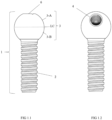
Figure 1.1 - which shows the front view of the implant with a spherical top (1); implant with spherical upper part (1), solid, rigid, in a single body and manufactured in titanium and/or surgical stainless steel, surmounted by the spherical part (3) containing an upper part (3-A) of spherical shape above the center line (LC), imaginary, and with a 0° thread hole (6) where the UCLA (8) will be fixed, and a lower part (3-B) of spherical or variable shape according to the shape and height of the patient's gum below the center line (LC), imaginary, and at the bottom the implant thread (2) for fixation on the bone structure. 8:1 scale. -
Figure 1.2 - which shows the front view of the implant with a spherical top (1); implant with spherical upper part (1), solid, rigid, in a single body and manufactured in titanium and/or surgical stainless steel, surmounted by the spherical part (3) containing an upper part (3-A) of spherical shape above the center line (LC), imaginary, and with a threaded hole up to 45° (4) where the UCLA (8) will be fixed, and a lower part (3-B) of spherical or variable shape according to the shape and height of the patient's gums below the imaginary center line (LC), and at the bottom the implant thread (2) for fixation on the bone structure. 8:1 scale. -
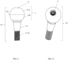
Figure 1.3 - showing the top perspective view of the implant with spherical top (1); implant with spherical upper part (1) solid, rigid and in a single body, surmounted by the spherical part (3), shows a triangular key fitting (5) together with the 0° thread (6) where the UCLA (8) will be fixed with the dental prosthesis, the lock (7) and the thread of the implant (2). No scale. -
Figure 1.4 - showing the top perspective view of the implant with spherical top (1) with UCLA (8); implant with spherical upper part (1), solid, rigid and in a single body, surmounted by the spherical part (3), where the UCLA (8) is installed, fixed to the thread up to 45° (4) through screw (9) and the thread of the implant (2). 8:1 scale. -
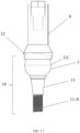
Figure 1.5 - which shows the front view of the implant with spherical top (1) with UCLA (8) with longitudinal section; implant with spherical upper part (1), solid, rigid and in a single body, surmounted by the spherical part (3), where the UCLA (8) is installed, fixed to the thread up to 45° (4) through screw (9) and the thread of the implant (2). 8:1 scale -
Figure 2.1 - which shows the front view of the CM spherical intermediate (10); CM spherical intermediate (10) composed of a spherical part (3) containing an upper part (3-A) of spherical shape above the centerline (LC), imaginary, and with a 0° threaded hole (6), and a lower part (3-B) spherical or variable in shape according to the shape and height of the patient's gums below the imaginary center line (LC) and in the lower part CM lower thread (11-A) of the standard morse cone type of market, and CM lock (13). 8:1 scale. -
Figure 2.2 - which shows the front perspective view of the CM spherical intermediate (10); CM spherical intermediate (10) composed of a spherical part (3) with thread indicative up to 45° (4), with lower thread (11) and CM locking (13), for fixation in implant with morse taper standard locking, found in the market. 8:1 scale. -
Figure 2.3 - which shows the front perspective view of the spherical intermediate CM (10) in longitudinal section; CM spherical intermediate (10), indicating the Lower thread (11), the triangular key fitting (5) together with the 0° thread (6), spherical part (3) and CM locking (13). No scale. -
Figure 2.4 - which shows the top view of the CM spherical intermediate (10); CM spherical intermediate (10) with triangular key socket (5) together with 0° thread (6). 8:1 scale. -
Figure 2.5 - which shows the front view of the CM spherical intermediate (10) and the UCLA (8); CM spherical intermediate (10) with the lower thread (11) and the CM locking (13) joined to the UCLA (8) in its spherical part (3). 8:1 scale. -
Figure 2.6 - which shows the front view of the front view of the spherical intermediate CM (10) and the UCLA (8) in longitudinal section; CM spherical intermediate (10), joined to the UCLA (8) in its spherical part (3) by screw (9); and the lower thread (11) and the CM lock (13). 8:1 scale. -
Figure 2.7 - which shows the front view of the CM (10) and UCLA (8) spherical intermediate; CM spherical intermediate (10), joined to the UCLA (8) in its spherical part (3), lower thread (11) and the CM locking (13), highlighting the concave fitting (12) of the UCLA (8). 8:1 scale. -
Figure 3.1 - which shows the front view of the spherical intermediate HE (14); spherical intermediate HE (14), with its spherical part (3) containing an upper (3-A) of convex shape, above the centerline (LC), imaginary, and a lower (3-B) of variable shape according to the shape and height of the patient's gums, below the imaginary center line (LC), indicating the 0° thread (6) and its spherical intermediate platform HE (15); shows the HE implant platform (16). No scale. -
Figure 3.2 - which shows the front view of the HI spherical intermediate (17); spherical intermediate HI (17) with its spherical part (3) containing an upper part (3-A) of convex shape, above the centerline (LC), imaginary, and a lower part (3-B) of variable shape of according to the shape and height of the patient's gums, below the imaginary center line (LC), with the thread up to 45° (4), and the HI implant (18). No scale. -
Figure 3.3 - which shows the bottom perspective view of the HE spherical intermediate; Spherical Intermediate HE (14), with the Spherical Intermediate HE Platform (15). No scale. -
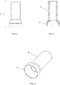
Figure 4.1 - which shows the front view of UCLA (8). 8:1 scale. -
Figure 4.2 - which shows the front view of the UCLA (8) seen in longitudinal section, with an indication of its concave fitting (12). 8:1 scale. -
Figure 4.3 - showing the bottom perspective view of UCLA (8) highlighting its concave fitting (12). No scale. - The installation process of the product described in this patent takes place in the following sequence:
- A) Before the application of implants or spherical intermediates in the mouth, the angulation of the spherical part (3) from 0 to 45° is defined according to the clinical need of each patient;
- B) The implant is threaded with a spherical upper part (1) more specifically the implant thread (2) into the patient's bone or CM spherical intermediate (10) more specifically CM lower thread (11-A) inside the morse cone implant, or spherical intermediate HE (14), more specifically the lower thread HE (11-B) inside the HE implant (16), or spherical intermediate HI (17), more specifically the lower thread HI (11-C) inside the HIimplant (18 ); and
- C) The screw (9) is screwed, fixing the 0° thread (6) or thread up to 45° (4) to the UCLA (8) of the implant with spherical upper part (1) or spherical intermediates CM (10) or HE (14) or HI (17).
Claims (5)
- "IMPLANTODONTICS WITH SPHERICAL COMPONENTS", This application for granting protection, for a Patent of Invention, is intended for some components with different configurations, but with the same inventive concept and purpose for the dental area, characterized by an implant with a spherical upper part (1), solid, rigid, in a single body and made of titanium and / or surgical stainless steel, surmounted by the spherical part (3) containing an upper part (3-A) of spherical shape above the center line (LC) and with hole with 0° (6) thread or hole with thread up to 45° (4) and fitting for triangular wrench (5) located in hole with 0° (6) thread or hole with thread up to 45° (4), and a lower part (3-B) spherical or variable in shape according to the shape and height of the patient's gums below the center line (LC), and at the bottom the implant thread (2) with lock (7), for fixation on the structure bone and with full sealing junction at the top (3-A) through UCLA (8) provided the concave fitting (12) at its bottom.
- "IMPLANTODONTICS WITH SPHERICAL COMPONENTS", consisting of a CM lower thread (11-A) and CM locking (13) for fixation in a morse cone implant, characterized by a CM spherical intermediate (10) manufactured in titanium and / or surgical stainless steel composed of part spherical (3) containing an upper (3-A) of spherical shape above the center line (LC) and with a 0° thread hole (6) or a threaded hole up to 45° (4) and fitting for a triangular wrench (5) located in the hole with thread 0° (6) or hole with thread up to 45° (4), and a lower part (3-B) of spherical or variable shape according to the shape and height of the patient's gums below the line of center (LC), and in the lower part CM lower thread (11-A) of the morse cone type and with full sealing joint in the upper part (3-A) through UCLA (8) with concave fitting (12) in its lower part.
- "IMPLANTODONTICS WITH SPHERICAL COMPONENTS", consisting of lower thread HE (11-B), characterized by spherical intermediate HE (14) manufactured in titanium and / or surgical stainless steel composed of a spherical part (3) containing an upper part (3-A) of spherical shape above the center line (LC) and with hole with 0° (6) thread or hole with thread up to 45° (4) and fitting for triangular wrench (5) located in hole with 0° (6) thread or hole with thread up to 45° (4), and a lower part (3-B) of spherical or variable shape according to the shape and height of the patient's gums below the center line (LC), and at the bottom of the spherical intermediate HE (14) thread lower HE (11-B) of the external hexagonal type and with full sealing joint in the upper part (3-A) through UCLA (8) equipped with a concave fitting (12) in its lower part.
- "IMPLANTODONTICS WITH SPHERICAL COMPONENTS", consisting of a lower thread HI (11-C), characterized by a spherical intermediate HI (17) manufactured in titanium and / or surgical stainless steel composed of a spherical part (3) containing an upper part (3-A) of spherical shape above the center line (LC) and with hole with 0° (6) thread or hole with thread up to 45° (4) and fitting for triangular wrench (5) located in hole with 0° (6) thread or hole with thread up to 45° (4), and a lower part (3-B) of spherical or variable shape according to the shape and height of the patient's gums below the center line (LC), and in the lower part lower thread HI (11-C) of the internal hexagonal type and with full sealing joint on the upper part (3-A) through UCLA (8) with a concave fitting (12) on its lower part.
- "IMPLANTODONTIC INSTALLATION PROCESS WITH SPHERICAL COMPONENTS", characterized by the following sequence:A) Before applying spherical implants or intermediates in the mouth, the angulation of the spherical part (3) from 0 to 45° is defined according to the clinical need of each patient;B) The implant is screwed with a spherical upper part (1) more specifically the implant thread (2) into the patient's bone or CM spherical intermediate (10) more specifically CM lower thread (11-A) inside the morse cone implant, or Spherical Intermediate HE (14) more specifically the lower thread HE (11-B) inside the HE implant (16), or Spherical Intermediate HI (17) more specifically the lower thread HI (11-C) inside the implant HI (18 ); andC) It is screwed with the screw (9), fixing the 0° thread (6) or thread up to 45° (4) to the UCLA (8) of the implant with spherical upper part (1) or spherical intermediates CM (10) or HE (14) or HI (17).
Applications Claiming Priority (2)
| Application Number | Priority Date | Filing Date | Title |
|---|---|---|---|
| BR202020011065 | 2020-06-02 | ||
| PCT/BR2021/050238 WO2021243430A1 (en) | 2020-06-02 | 2021-06-01 | Dental implantology using spherical components |
Publications (1)
| Publication Number | Publication Date |
|---|---|
| EP4147667A1 true EP4147667A1 (en) | 2023-03-15 |
Family
ID=78831434
Family Applications (1)
| Application Number | Title | Priority Date | Filing Date |
|---|---|---|---|
| EP21817568.5A Pending EP4147667A1 (en) | 2020-06-02 | 2021-06-01 | Dental implantology using spherical components |
Country Status (9)
| Country | Link |
|---|---|
| US (1) | US20220280268A1 (en) |
| EP (1) | EP4147667A1 (en) |
| CN (1) | CN115397359A (en) |
| AU (1) | AU2021284920A1 (en) |
| CA (1) | CA3183087A1 (en) |
| IL (1) | IL298722A (en) |
| MX (1) | MX2022015073A (en) |
| WO (1) | WO2021243430A1 (en) |
| ZA (1) | ZA202213425B (en) |
Family Cites Families (10)
| Publication number | Priority date | Publication date | Assignee | Title |
|---|---|---|---|---|
| DE3531389A1 (en) * | 1985-09-03 | 1987-03-05 | Kirsch Axel | ENOSSAL IMPLANT |
| US4842518A (en) | 1986-09-04 | 1989-06-27 | Vent-Plant Corporation | Submergible screw-type dental implant and method of utilization |
| US4907969A (en) * | 1988-04-14 | 1990-03-13 | Ward Whitley S | Universal dental prosthesis retention system |
| US5520540A (en) * | 1992-06-19 | 1996-05-28 | Rhein 83 S.N.C. Di Nardi Ezio & C. Zago, 10 | Quick coupling device for dental prosthesis |
| US5302125A (en) | 1992-10-22 | 1994-04-12 | Kownacki Charles D | Dental prosthetic implant |
| ES2278477B1 (en) * | 2004-07-30 | 2008-06-01 | Esteban Xam-Mar Mangrane | Dynamic pier for correcting implants in bone, has base and shaft so that the base has hemispherical configuration and end of shaft coupled to base has complementary configuration |
| BRMU8803485Y8 (en) * | 2008-12-18 | 2021-06-22 | D S P Ind Ltda Me | constructive disposition of integrable bone implant of multiple use and interchangeability in a single body |
| KR101065924B1 (en) * | 2011-03-09 | 2011-09-19 | 박영일 | Implant for dental |
| ES2386589B2 (en) * | 2012-04-02 | 2013-03-25 | Terrats Mecanizados, S.L. | PROTESTIC ADDITION |
| CN113286561B (en) * | 2018-11-15 | 2023-10-31 | 乌戈·加斯帕隆 | Dental implant |
-
2020
- 2020-06-01 US US17/632,696 patent/US20220280268A1/en active Pending
-
2021
- 2021-06-01 MX MX2022015073A patent/MX2022015073A/en unknown
- 2021-06-01 CA CA3183087A patent/CA3183087A1/en active Pending
- 2021-06-01 IL IL298722A patent/IL298722A/en unknown
- 2021-06-01 CN CN202180025607.3A patent/CN115397359A/en active Pending
- 2021-06-01 WO PCT/BR2021/050238 patent/WO2021243430A1/en unknown
- 2021-06-01 AU AU2021284920A patent/AU2021284920A1/en active Pending
- 2021-06-01 EP EP21817568.5A patent/EP4147667A1/en active Pending
-
2022
- 2022-12-12 ZA ZA2022/13425A patent/ZA202213425B/en unknown
Also Published As
| Publication number | Publication date |
|---|---|
| ZA202213425B (en) | 2023-10-25 |
| US20220280268A1 (en) | 2022-09-08 |
| WO2021243430A1 (en) | 2021-12-09 |
| MX2022015073A (en) | 2023-01-11 |
| AU2021284920A1 (en) | 2023-01-05 |
| CN115397359A (en) | 2022-11-25 |
| CA3183087A1 (en) | 2021-12-09 |
| IL298722A (en) | 2023-02-01 |
Similar Documents
| Publication | Publication Date | Title |
|---|---|---|
| US5135395A (en) | Implant collar and post system | |
| US5564921A (en) | Method of forming an abutment post | |
| EP0963183B1 (en) | Bone-anchoring element | |
| US8827704B2 (en) | System, method and apparatus for implementing dental implants | |
| KR101777144B1 (en) | Fixed detachable dental attachment device, assembly and methods of using the same | |
| US20040259056A1 (en) | Prosthetic implant | |
| JP2574695B2 (en) | Spacer | |
| US20110244425A1 (en) | Universal healing abutment | |
| KR100807150B1 (en) | Implant for overdenture | |
| EP4147667A1 (en) | Dental implantology using spherical components | |
| KR101524192B1 (en) | Cervical Shape Abutment for Dental Implant | |
| KR200392276Y1 (en) | Dental Implant | |
| KR200392241Y1 (en) | Dental Temporary Implant | |
| KR20140113996A (en) | Dental implant | |
| BR102021010680A2 (en) | Implantology with spherical components | |
| EP4018964A1 (en) | One-piece tissue level ceramic dental implant with a dual internal and external connection for a custom-made dental restoration | |
| EP4076268B1 (en) | Transepithelial abutment | |
| EP3888587A1 (en) | Transepithelial abutment | |
| KR200493322Y1 (en) | Dental implant | |
| KR20240040796A (en) | Dental attachment assembly, angled implant assembly, and method of use | |
| IL264788A (en) | Dynamic modular dental prosthesis | |
| LOOKS | Practical implantology, part three |
Legal Events
| Date | Code | Title | Description |
|---|---|---|---|
| STAA | Information on the status of an ep patent application or granted ep patent |
Free format text: STATUS: THE INTERNATIONAL PUBLICATION HAS BEEN MADE |
|
| PUAI | Public reference made under article 153(3) epc to a published international application that has entered the european phase |
Free format text: ORIGINAL CODE: 0009012 |
|
| STAA | Information on the status of an ep patent application or granted ep patent |
Free format text: STATUS: REQUEST FOR EXAMINATION WAS MADE |
|
| 17P | Request for examination filed |
Effective date: 20221205 |
|
| AK | Designated contracting states |
Kind code of ref document: A1 Designated state(s): AL AT BE BG CH CY CZ DE DK EE ES FI FR GB GR HR HU IE IS IT LI LT LU LV MC MK MT NL NO PL PT RO RS SE SI SK SM TR |
|
| DAV | Request for validation of the european patent (deleted) | ||
| DAX | Request for extension of the european patent (deleted) |