EP4147616A1 - Control unit and method for performing tool detection and/or control - Google Patents
Control unit and method for performing tool detection and/or control Download PDFInfo
- Publication number
- EP4147616A1 EP4147616A1 EP21196564.5A EP21196564A EP4147616A1 EP 4147616 A1 EP4147616 A1 EP 4147616A1 EP 21196564 A EP21196564 A EP 21196564A EP 4147616 A1 EP4147616 A1 EP 4147616A1
- Authority
- EP
- European Patent Office
- Prior art keywords
- temperature
- tool
- content
- control unit
- receptacle
- Prior art date
- Legal status (The legal status is an assumption and is not a legal conclusion. Google has not performed a legal analysis and makes no representation as to the accuracy of the status listed.)
- Granted
Links
Images

Classifications
-
- A—HUMAN NECESSITIES
- A47—FURNITURE; DOMESTIC ARTICLES OR APPLIANCES; COFFEE MILLS; SPICE MILLS; SUCTION CLEANERS IN GENERAL
- A47J—KITCHEN EQUIPMENT; COFFEE MILLS; SPICE MILLS; APPARATUS FOR MAKING BEVERAGES
- A47J36/00—Parts, details or accessories of cooking-vessels
- A47J36/32—Time-controlled igniting mechanisms or alarm devices
-
- A—HUMAN NECESSITIES
- A47—FURNITURE; DOMESTIC ARTICLES OR APPLIANCES; COFFEE MILLS; SPICE MILLS; SUCTION CLEANERS IN GENERAL
- A47J—KITCHEN EQUIPMENT; COFFEE MILLS; SPICE MILLS; APPARATUS FOR MAKING BEVERAGES
- A47J43/00—Implements for preparing or holding food, not provided for in other groups of this subclass
- A47J43/04—Machines for domestic use not covered elsewhere, e.g. for grinding, mixing, stirring, kneading, emulsifying, whipping or beating foodstuffs, e.g. power-driven
- A47J43/07—Parts or details, e.g. mixing tools, whipping tools
-
- A—HUMAN NECESSITIES
- A47—FURNITURE; DOMESTIC ARTICLES OR APPLIANCES; COFFEE MILLS; SPICE MILLS; SUCTION CLEANERS IN GENERAL
- A47J—KITCHEN EQUIPMENT; COFFEE MILLS; SPICE MILLS; APPARATUS FOR MAKING BEVERAGES
- A47J2202/00—Devices having temperature indicating means
Definitions
- the present document relates to a kitchen appliance.
- the present document relates to managing the use of one or more tools within a kitchen appliance.
- a kitchen appliance may be used with various different tools for performing different processing of a food item which is placed within the receptacle, in particular within the bowl, of the appliance.
- Example tools are a knife, a shredder, a dough hook, etc. Operation of the appliance may be adapted depending on the tool which is attached to the appliance.
- the kitchen appliance may be configured to automatically guide a user through a cooking process using recipe data stored on the kitchen appliance.
- the user may be requested via a user interface of the kitchen appliance to place a particular tool within the receptacle of the appliance.
- the tool may then be operated automatically in dependence of the recipe data.
- the user may forget to place a tool within the receptacle, or the user may place the wrong tool within the receptacle. This typically impacts the quality of the food item which is prepared within the kitchen appliance.
- the present document addresses the technical problem of performing tool detection and/or of controlling a tool in an efficient and reliable manner.
- the technical problem is solved by each of the independent claims. Preferred examples are described in the dependent claims.
- a control unit for an appliance in particular for a kitchen and/or cooking appliance, is described.
- the appliance comprises a receptacle, in particular a bowl, for taking up content, in particular a food item.
- the appliance comprises a temperature modification unit, in particular a heating unit and/or a cooling unit, for modifying the temperature of (in particular for heating up and/or for cooling down) the content within the receptacle.
- the temperature modification unit may be configured to provide thermal energy to and/or to withdraw thermal energy from the receptacle and/or the content within the receptacle at an (energy) transfer point.
- the transfer point may be located at the bottom of the receptacle.
- the appliance is configured to operate a tool to process the content within the receptacle.
- the appliance typically comprises a motor configured to drive the tool which is attached to the motor.
- Example tools are a knife, a shredder, a hook, a foaming tool, etc.
- the motor may be integrated within a base unit of the appliance, wherein the base unit may be configured to be placed on a worktop of a kitchen.
- the receptacle may be positioned on top of the base unit.
- the appliance may be configured such that the tool which is attached to and/or driven by the motor is selectable in an interchangeable manner from a set of K different tools, with K ⁇ 2 (typically K ⁇ 5 or K ⁇ 10).
- K ⁇ 2 typically K ⁇ 5 or K ⁇ 10
- a user may be enabled to position (sequentially) K different tools onto a coupling of the appliance.
- the coupling may be located within the receptacle.
- the coupling may be coupled to the motor, and the motor may be configured to drive a tool via the coupling.
- the appliance comprises a temperature sensor (e.g., an Infrared (IR) based sensor and/or a resistance-based sensor) configured to provide measurement data regarding the temperature of the content.
- the temperature of the content may be sensed at a measurement point, wherein the location of the measurement point may differ from the location of the transfer point.
- the measurement point may be located at a higher level than the transfer point (e.g., at a side wall of the receptacle), e.g., at a height of 2cm or more, or 5cm or more above the transfer point.
- the control unit is configured to determine, based on measurement data provided by the temperature sensor, a temperature signal which is indicative of the temperature of the content within the receptacle as a function of time, during operation of the temperature modification unit for modifying (in particular for increasing or for decreasing) the temperature of the content within the receptacle.
- a temperature signal may be determined, which indicates the temporal evolution of the temperature of the content (at the measurement point of the temperature sensor).
- it may be determined how the temperature of the content increases and/or decreases during operation of the temperature modification unit (and possibly during operation of the tool).
- control unit is configured to determine tool information regarding the tool and/or regarding operation of the tool, based on the temperature signal.
- the temporal evolution of the temperature of the content during a heat-up or cool-down process may be analyzed to determine tool information.
- the tool information may be indicative of whether or not the tool is operated.
- the tool information may be indicative of the rotation speed of the tool.
- the tool information may be indicative of the type of the tool out of a pre-determined set of K different types of tools, with K>1.
- control unit which makes use of temperature measurement data regarding the temperature of the content of the appliance, in order to determine tool information regarding the tool that is being used within the appliance. This allows tool information to be determined in a reliable, precise and efficient manner.
- the control unit may be configured to monitor and/or to control operation of the tool based on the determined tool information.
- the tool information may indicate the actual rotation speed of the tool. This information may be used to control the motor for driving the tool, e.g., in order to regulate the rotation speed of the tool to a target rotation speed.
- the tool information may indicate the type of the tool, which is being operated within the receptacle. The motor for driving the tool may be operated in dependence of the indicated type of the tool, thereby increase the safety and/or the reliability of the appliance.
- the control unit may be configured to operate the appliance in dependence of the tool information.
- the appliance may be configured to provide a guided cooking function via a user interface of the appliance.
- the control unit may be configured to determine recipe data regarding a recipe to be cooked using the appliance.
- the recipe data may indicate a particular type of tool to be used.
- the control unit may be configured to instruct the user of the appliance to place the indicated type of tool within the receptacle.
- the control unit may be configured to operate the tool (subject to a user input by the user via the user interface).
- the control unit may be configured to determine tool information regarding the tool (as outlined in the present document). The tool information may be used to verify whether or not the correct type of tool has been placed into the receptacle.
- an error message may be output via the user interface of the appliance. As a result of this, the reliability of the appliance may be improved (in particular, with regards to a guided cooking function).
- the control unit may be configured to determine whether or not the temperature signal comprises one or more localized temperature spikes (in particular, a (periodic) sequence of localized temperature spikes).
- the one or more localized temperature spikes, in particular the sequence of localized temperature spikes may be determined in a reliable manner using a pattern recognition algorithm and/or using a frequency analysis of the temperature signal.
- the temperature signal may show a smooth overall increase or decrease in temperature, wherein the temperature may increase or decrease according to an average temperature gradient. This smooth increase or decrease may be overlayed with relative short temperature spikes (within which the temperature increases and/or decreases in an abrupt manner).
- the duration and/or the height of a temperature spike may be dependent on the rotation speed of the tool. Typically, the duration of a temperature spike and/or the height of a temperature spike decreases with increasing rotation speed (and vice versa).
- the control unit may be configured to determine the rotation speed of the tool (based on motor information regarding the motor of the appliance). Furthermore, the control unit may be configured to search for one or more localized temperature spikes in dependence of the rotation speed of the tool (indicated within the motor information). In particular, the control unit may be configured to look for one or more localized temperature spikes, which are consistent with the determined rotation speed of the tool (in particular, consistent with regards to the duration, the height and/or the period of the localized temperature spikes). As a result of this, one or more localized temperature spikes may be determined in a particularly reliable manner.
- the control unit may be configured to determine the tool information based on the presence or the absence of one or more localized temperature spikes. In particular, it may be determined as tool information that the tool is being operated, if it is determined that the temperature signal comprises one or more localized temperature spikes. On the other hand, it may be determined as tool information that the tool is not being operated, if it is determined that the temperature signal does not comprise one or more localized temperature spikes.
- the control unit may be configured to determine a period (i.e., a time duration) between two successive temperature spikes within the temperature signal.
- the tool information in particular the rotation speed and/or the type of the tool, may then be determined in a particularly precise manner based on the determined period between two successive temperature spikes within the temperature signal.
- the control unit may be configured to determine the temperature gradient of the temperature signal.
- the average temperature gradient of the smoothly increasing or decreasing portion of the temperature signal (without the one or more temperature spikes) may be determined.
- the tool information in particular, the rotation speed of the tool and/or the type of the tool, may be determined in a particularly precise manner based on the temperature gradient.
- the control unit may be configured to perform a frequency analysis of the temperature signal to determine a spectrum of the temperature signal. For this purpose, a Fourier Transform may be used.
- the tool information in particular, the rotation speed of the tool and/or the type of the tool, may be determined in a particularly precise manner based on the spectrum of the temperature signal.
- the control unit may be configured to compare the temperature signal with a reference temperature signal.
- the control unit may be configured to compare the temperature signal with a set of K different reference temperature signals for the corresponding set of K different types of tools.
- the one or more reference temperature signals may have been determined beforehand. Alternatively, or in addition, the one or more reference temperature signals may have been stored on a storage unit of the appliance.
- the one or more reference temperature signals may be dependent on power information regarding the power with which the temperature modification unit is being operated. Alternatively, or in addition, the one or more reference temperature signals may be dependent on motor information regarding the operation (in particular, the rotation speed) of the motor for driving the tool. Alternatively, or in addition, the one or more reference temperature signals may be dependent on content information regarding the content (in particular, the weight and/or of the type of the content) within the receptacle.
- control unit may be configured to determine the power information, the motor information and/or the content information. Furthermore, the control unit may be configured to determine, in particular to select, the one or more reference temperature signals (in particular, the set of K different reference temperature signals), in dependence of the power information, the motor information and/or the content information.
- the one or more reference temperature signals in particular, the set of K different reference temperature signals
- the tool information in particular, the rotation speed of the tool and/or the type of the tool, may be determined in a particularly precise manner based on the comparison, in particular, based on the comparison of the temperature signal with the set of K different reference temperature signals.
- control unit may be configured to determine power information regarding the power with which the temperature modification unit is being operated, in particular to heat-up or to cool-down the content within the receptacle.
- the power of the temperature modification unit typically has an impact on the temperature gradient of the temperature signal and/or on the height of the temperature spikes.
- the tool information in particular, the rotation speed of the tool and/or the type of the tool, may be determined in a particularly precise manner based on the power information.
- the control unit may be configured to determine motor information regarding the operation of the motor for driving the tool.
- the motor information may be indicative of the rotation speed of the motor.
- the motor information may be used for identifying the one or more temperature spikes and/or for selecting an appropriate reference temperature signal.
- the tool information in particular, the rotation speed of the tool and/or the type of the tool, may be determined in a particularly precise manner based on the motor information.
- the control unit may be configured to determine content information regarding the content within the receptacle.
- the content information may be indicative of the weight and/or of the type of the content.
- the content information may be determined using a weight sensor of the appliance and/or using recipe data for a guided cooking process and/or using user input provided by a user of the appliance via the user interface of the appliance.
- the content information typically has an impact on the temperature gradient of the temperature signal and/or on the shape of the temperature spikes.
- the tool information in particular, the rotation speed of the tool and/or the type of the tool, may be determined in a particularly precise manner based on the content information.
- an appliance in particular a kitchen and/or cooking appliance, is described.
- the appliance comprises a receptacle for taking up content (in particular a food item).
- the appliance comprises a temperature modification unit, in particular a heating unit and/or a cooling unit, for modifying the temperature of the content within the receptacle.
- the temperature modification unit may be configured to modify the temperature of the content at a transfer point (for transferring thermal energy).
- the appliance further comprises a tool for processing the content within the receptacle.
- the tool may be operated using a motor of the appliance.
- the appliance comprises a temperature sensor configured to provide measurement data regarding the temperature of the content. The measurement data may be sensed at a measurement point. The locations of the transfer point and of the measurement point may differ from one another.
- the appliance comprises a control unit (in particular as described in the present document).
- the control unit may be configured to determine tool information regarding the tool and/or regarding operation of the tool, based on the measurement data of the temperature sensor, in particular based on the temporal evolution of the measured temperature of the content of the receptacle during a heat-up and/or cool-down process.
- a method for determining tool information regarding a tool and/or regarding operation of a tool of an appliance, in particular of a kitchen appliance comprises determining, based on measurement data provided by a temperature sensor of the appliance, a temperature signal indicative of the temperature of the content within the receptacle of the appliance as a function of time, during operation of the temperature modification unit of the appliance for modifying, in particular for increasing or for decreasing, the temperature of the content within the receptacle.
- the method further comprises determining tool information regarding the tool and/or regarding operation of the tool, based on the temperature signal.
- the tool information may be used to monitor and/or to control operation of the tool.
- a software program is described.
- the software program may be adapted for execution on a processor and for performing the method steps outlined in the present document when carried out on the processor.
- the storage medium may comprise a software program adapted for execution on a processor and for performing the method steps outlined in the present document when carried out on the processor.
- the computer program may comprise executable instructions for performing the method steps outlined in the present document when executed on a computer.
- Fig. 1a shows a block diagram of an example appliance 100 which comprises a base unit 103 on which a receptacle 104, in particular a bowl, is placed.
- the receptacle 104 may be configured to be covered by a lid 109.
- the base unit 103 comprises a motor 102 which is configured to drive a tool 107 which is located within the receptable 104.
- the tool 107 may be detachable and/or exchangeable.
- the appliance 100 may be configured to be used with an arbitrary tool 107 out of a pre-determined set of K different tools 107.
- the appliance 100 may comprise a heating unit 105 (which may alternatively, or in addition, be integrated into the receptacle 104) for heating the receptacle 104, e.g., for allowing a food item to be cooked within the receptacle 104.
- the heating unit 105 is an example for a temperature modification unit 105 which is configured to modify the temperature of the content within the receptacle 104.
- the appliance 100 may comprise a temperature sensor 106 which is configured to provide sensor data regarding the temperature of the food item within the receptacle 104.
- the appliance 100 may comprise a user interface 108 which allows a user to interact with the appliance 100, e.g., for activating or for deactivating the motor 102.
- the appliance 100 may be connected to the internet, to another appliance and/or to a (smart) device via a (wireless) communication interface such as WLAN.
- a control unit 101 of the appliance 100 may be configured to operate the appliance 100, in particular the motor 102 and/or the heating unit 105, in dependence of a user input received via the user interface 108 (of the appliance 100 or of a remote device).
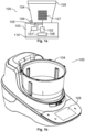
- Fig. 1b shows a perspective view of an exemplary appliance 100.
- Operation of the appliance 100 may vary depending on the tool 107 which is being used within the receptacle 104.
- the rotation speed, in particular a maximum speed, of the motor 102 may be dependent on the tool 107 which is being used.
- the control unit 101 may be configured to request the user via the user interface 108 to manually identify the tool 107 that has been placed within the receptacle 104 and/or to manually insert a particular tool 107 into the receptacle 104.
- Such a manual identification and/or placement process is prone to errors, which may impact the quality of the food item that is being processed within the receptacle 104.
- Fig. 2 shows the receptacle 104 of an appliance 100, which contains a food item 200 that is being processed using a tool 107.
- Operation of the tool 107 causes the food item 200 to be moved around within the receptacle 104.
- relatively cold portions of the food item 200 may be moved downwards 201 towards the bottom of the receptacle 104 (where the heating unit 105 may be located).
- relatively hot portions of the food item 200 may be moved upwards 202 towards the top of the receptacle 104.
- This movement of different portions of the food item 200 which are at different temperatures, may be used to determine information regarding the tool 107 that is located and/or operated within the receptacle 104.
- the measurement data of the one or more temperature sensors 106 of the appliance 100 may be used to determine information regarding the tool 107 that is located and/or operated within the receptacle 104. This information is referred to as "tool information" within the present document.
- Fig. 3 shows example temperature signals 311, 312 which are indicative of the measured temperature 302 of the food item 200 as a function of time 301.
- the measured temperature 302 at a particular time instant may be determined based on measurement data provided by the one or more temperature sensors 106 of the appliance 100 at the particular time instant.
- Example temperature sensors 106 are an Infrared (IR) based temperature sensor and a Resistance Temperature Device (RTD) sensor.
- IR Infrared
- RTD Resistance Temperature Device
- the first temperature signal 311 corresponds to a situation, where the food item 200 is heated up (up to the target temperature 303 which may have been set by the user and/or which may depend on recipe data) without operation of a tool 107 within the receptacle 104.
- the measured temperature 302 (which is typically measured at a particular measurement point on the receptacle 104) increases smoothly up to the target temperature 303.
- Fig. 3 shows a second temperature signal 312 which corresponds to a situation, where the food item 200 is heated up, while a tool 107 is being operated within the receptacle 104.
- the second temperature signal 312 comprises local temperature spikes 313, which are due to the tool 107 (e.g., the blade of a knife) passing by the measurement point of the one or more temperature sensors 106.
- the local spikes 313 have a period 314 which is dependent on the rotation speed of the tool 107.
- the tool 107 is a knife with N blades
- a group of N consecutive spikes 313 may correspond to a full rotation of the tool 107.
- the presence of (possibly periodic) spikes 313 within a temperature signal 312 may be used as an indication that a tool 107 is being operated within the receptacle 104.
- the period 314 of the spikes 313, i.e., the time duration between two consecutive spikes 313, may be used as an indication of the rotation speed of the tool 107 and/or as an indication of the type of the tool 107.
- the shape of the spikes 313 may be analyzed to determine the type of the tool 107 which is being operated within the receptacle 104.
- the second temperature signal 312 (with operation of a tool 107) increases faster than the first temperature signal 311 (without operation of a tool 107).
- the temperature gradient of the second temperature signal 312 is higher than the temperature gradient of the first temperature signal 311.
- the temperature gradient of the temperature signal 311, 312 may be used to determine tool information regarding the tool 107 which is located within the receptacle 104.
- a food preparation and/or cooking machine 100 which is equipped with one or more temperature sensors 106 that measure the temperature 302 of the bowl content 200 (in particular food).
- a temperature sensor 106 may be located at the bottom of the bowl 104. Alternatively, or in addition, a temperature sensor 106 may be located at the side of the bowl 104. A temperature sensor 106 may be integrated within the bowl 104 or touching the bowl 104.
- a contact-based sensor such as an RTD sensor
- a contactless sensor such as an IR thermopile or an array sensor or a thermocouple, may be used.
- sudden temperature changes 313, e.g., spikes, may be observed within the temperature signal 312 regarding the temperature 302 of the bowl content 200, during tool operation.
- relatively fast temperature changes 313 as a consequence of a rotating motorized tool 107 which is processing the bowl content 200 may be observed. This information may be used to check and/or control the tool operation.
- one or more temperature sensors 106 may be used to measure the temperature 302 of the content 200 (in particular, food) within the bowl 104.
- the content 200 may be processed using heat and a motorized tool 107, like a stirrer or a whisk. If the tool 107 performs a mixing function, then the tool 107 moves the relatively hot content 200 from the bottom side of the bowl 104 into the upward direction 202, and the relatively cold content 200 in the downward direction 201, where the content 200 will be heated up. Overall, the function of mixing-up the content 200 speeds up the heat-up process and ensures a homogeneous temperature 302 of the content 200 within the bowl 104.
- the mixing effect creates sudden temperature changes 313, in particular spikes, that are visible on the temperature sensor measurement 312. These sudden temperature changes 313 have the same frequency as the tool rotation and/or as the mixing interval.
- the temperature 302 of the content 200 increases relatively slowly and without any sudden changes 313 that occur because of the mixing effect of the tool 107.
- the temperature 302 of the content 200 increases at an increased speed and the tool generates sudden temperature changes 313 that are visible on the temperature sensor measurement, i.e., on the temperature signal 312.
- a temperature gradient and/or frequency of repetition analysis may be performed, in order to detect a rotating tool inside the appliance 100. Furthermore, in particular in case of a known tool 107, tool operation may be measured and/or controlled based on the temperature signal 312.
- Fig. 4 shows a flow chart of an example (possibly computer-implemented) method 400 for determining tool information regarding a tool 107 and/or regarding operation of a tool 107 of an appliance 100.
- the method 400 may be executed by a control unit 101 of the appliance 100.
- the appliance 100 comprises a receptacle 104 (also referred to herein as a bowl) for taking up content 200, in particular a food item. Furthermore, the appliance 100 comprises a temperature modification unit 105, in particular a heating unit and/or a cooling unit, for modifying the temperature 302 of the content 200 within the receptacle 104.
- the temperature medication unit 105 may be configured to provide thermal energy to the content 200 for heating up the content 200. Alternatively, or in addition, the temperature modification unit 105 may be configured to withdraw thermal energy from the content 200 for cooling down the content 200.
- the energy transfer between the temperature modification unit 105 and the content 200 may occur at a transfer point, wherein the transfer point may be located at the bottom of the receptacle 104.
- the appliance 100 is configured to operate a (exchangeable) tool 107 to process the content 200 within the receptacle 104.
- the tool 107 may be configured to be operated at variable rotation speeds.
- the appliance 100 may be configured to take up different types of tools 107 (e.g., a knife, a shredder, a dough hook, etc.).
- the tool 107 may be configured to mix up the content 200 within the receptacle 104.
- the appliance 100 comprises one or more temperature sensors 106 configured to provide measurement data regarding the temperature 302 of the content 200.
- the temperature sensor 106 may be a contact-based or a contactless sensor.
- Example temperature sensors 106 are an IR-based sensor and/or a resistor-based sensor.
- a temperature sensor 106 may be configured to sense the measurement data at a measurement point (which may be located at or within the receptacle 104).
- the locations of the measurement points of the one or more temperature sensor 106 typically differ from the location of the transfer point of the temperature modification unit 105.
- the one or more measurement points may be separated from the transfer point by a minimum distance (e.g., 5cm or more, or 10cm or more).
- the one or more measurement points are located above the transfer point (e.g., 2cm or more, or 5cm or more above the transfer point).
- measurement data may be sensed by the one or more temperature sensors 106, which allows the determination of particularly precise and/or reliable tool information.
- the method 400 comprises determining 401, based on the measurement data provided by the one or more temperature sensors 106, a temperature signal 311, 312 which is indicative of the temperature 302 of the content 200 within the receptacle 104 as a function of time 301, during operation of the temperature modification unit 105 for modifying (in particular, for increasing or for decreasing) the temperature 302 of the content 200 within the receptacle 104.
- a temperature signal 311, 312 may be determined, which indicates how the temperature 302 of the content 200 is increasing or decreasing over time 301, while the temperature modification unit 105 is being operated.
- the method 400 comprises determining 402 the tool information regarding the tool 107 and/or regarding the operation of the tool 107, based on the temperature signal 311, 312, in particular based on the temporal evolution of the increase or the decrease of the temperature 302 of the content 200. In particular, it may be determined whether or not the tool 107 is being operated. Alternatively, or in addition, the type of the tool 107 and/or the rotation speed of the tool 107 may be determined.
Landscapes
- Engineering & Computer Science (AREA)
- Food Science & Technology (AREA)
- Mechanical Engineering (AREA)
- Food-Manufacturing Devices (AREA)
Abstract
Description
- The present document relates to a kitchen appliance. In particular, the present document relates to managing the use of one or more tools within a kitchen appliance.
- A kitchen appliance may be used with various different tools for performing different processing of a food item which is placed within the receptacle, in particular within the bowl, of the appliance. Example tools are a knife, a shredder, a dough hook, etc. Operation of the appliance may be adapted depending on the tool which is attached to the appliance.
- The kitchen appliance may be configured to automatically guide a user through a cooking process using recipe data stored on the kitchen appliance. During the guided cooking process, the user may be requested via a user interface of the kitchen appliance to place a particular tool within the receptacle of the appliance. The tool may then be operated automatically in dependence of the recipe data.
- The user may forget to place a tool within the receptacle, or the user may place the wrong tool within the receptacle. This typically impacts the quality of the food item which is prepared within the kitchen appliance.
- The present document addresses the technical problem of performing tool detection and/or of controlling a tool in an efficient and reliable manner. The technical problem is solved by each of the independent claims. Preferred examples are described in the dependent claims.
- According to an aspect, a control unit for an appliance, in particular for a kitchen and/or cooking appliance, is described. The appliance comprises a receptacle, in particular a bowl, for taking up content, in particular a food item. Furthermore, the appliance comprises a temperature modification unit, in particular a heating unit and/or a cooling unit, for modifying the temperature of (in particular for heating up and/or for cooling down) the content within the receptacle. The temperature modification unit may be configured to provide thermal energy to and/or to withdraw thermal energy from the receptacle and/or the content within the receptacle at an (energy) transfer point. The transfer point may be located at the bottom of the receptacle.
- The appliance is configured to operate a tool to process the content within the receptacle. The appliance typically comprises a motor configured to drive the tool which is attached to the motor. Example tools are a knife, a shredder, a hook, a foaming tool, etc. The motor may be integrated within a base unit of the appliance, wherein the base unit may be configured to be placed on a worktop of a kitchen. The receptacle may be positioned on top of the base unit.
- The appliance may be configured such that the tool which is attached to and/or driven by the motor is selectable in an interchangeable manner from a set of K different tools, with K ≥ 2 (typically K≥ 5 or K≥ 10). By way of example, a user may be enabled to position (sequentially) K different tools onto a coupling of the appliance. The coupling may be located within the receptacle. The coupling may be coupled to the motor, and the motor may be configured to drive a tool via the coupling.
- Furthermore, the appliance comprises a temperature sensor (e.g., an Infrared (IR) based sensor and/or a resistance-based sensor) configured to provide measurement data regarding the temperature of the content. The temperature of the content may be sensed at a measurement point, wherein the location of the measurement point may differ from the location of the transfer point. In particular, the measurement point may be located at a higher level than the transfer point (e.g., at a side wall of the receptacle), e.g., at a height of 2cm or more, or 5cm or more above the transfer point.
- The control unit is configured to determine, based on measurement data provided by the temperature sensor, a temperature signal which is indicative of the temperature of the content within the receptacle as a function of time, during operation of the temperature modification unit for modifying (in particular for increasing or for decreasing) the temperature of the content within the receptacle. In other words, during a heat-up or cool-down process performed by the temperature modification unit, a temperature signal may be determined, which indicates the temporal evolution of the temperature of the content (at the measurement point of the temperature sensor). In yet other words, it may be determined how the temperature of the content increases and/or decreases during operation of the temperature modification unit (and possibly during operation of the tool).
- Furthermore, the control unit is configured to determine tool information regarding the tool and/or regarding operation of the tool, based on the temperature signal. In other words, the temporal evolution of the temperature of the content during a heat-up or cool-down process may be analyzed to determine tool information. The tool information may be indicative of whether or not the tool is operated. Alternatively, or in addition, the tool information may be indicative of the rotation speed of the tool. Alternatively, or in addition, the tool information may be indicative of the type of the tool out of a pre-determined set of K different types of tools, with K>1.
- Hence, a control unit is described, which makes use of temperature measurement data regarding the temperature of the content of the appliance, in order to determine tool information regarding the tool that is being used within the appliance. This allows tool information to be determined in a reliable, precise and efficient manner.
- The control unit may be configured to monitor and/or to control operation of the tool based on the determined tool information. By way of example, the tool information may indicate the actual rotation speed of the tool. This information may be used to control the motor for driving the tool, e.g., in order to regulate the rotation speed of the tool to a target rotation speed. Alternatively, or in addition, the tool information may indicate the type of the tool, which is being operated within the receptacle. The motor for driving the tool may be operated in dependence of the indicated type of the tool, thereby increase the safety and/or the reliability of the appliance.
- The control unit may be configured to operate the appliance in dependence of the tool information. By way of example, the appliance may be configured to provide a guided cooking function via a user interface of the appliance. The control unit may be configured to determine recipe data regarding a recipe to be cooked using the appliance. The recipe data may indicate a particular type of tool to be used. The control unit may be configured to instruct the user of the appliance to place the indicated type of tool within the receptacle. Furthermore, the control unit may be configured to operate the tool (subject to a user input by the user via the user interface). In addition, the control unit may be configured to determine tool information regarding the tool (as outlined in the present document). The tool information may be used to verify whether or not the correct type of tool has been placed into the receptacle. If it is determined that the incorrect type of tool or no tool has been placed into the receptacle, an error message may be output via the user interface of the appliance. As a result of this, the reliability of the appliance may be improved (in particular, with regards to a guided cooking function).
- The control unit may be configured to determine whether or not the temperature signal comprises one or more localized temperature spikes (in particular, a (periodic) sequence of localized temperature spikes). The one or more localized temperature spikes, in particular the sequence of localized temperature spikes, may be determined in a reliable manner using a pattern recognition algorithm and/or using a frequency analysis of the temperature signal. The temperature signal may show a smooth overall increase or decrease in temperature, wherein the temperature may increase or decrease according to an average temperature gradient. This smooth increase or decrease may be overlayed with relative short temperature spikes (within which the temperature increases and/or decreases in an abrupt manner). The duration and/or the height of a temperature spike may be dependent on the rotation speed of the tool. Typically, the duration of a temperature spike and/or the height of a temperature spike decreases with increasing rotation speed (and vice versa).
- The control unit may be configured to determine the rotation speed of the tool (based on motor information regarding the motor of the appliance). Furthermore, the control unit may be configured to search for one or more localized temperature spikes in dependence of the rotation speed of the tool (indicated within the motor information). In particular, the control unit may be configured to look for one or more localized temperature spikes, which are consistent with the determined rotation speed of the tool (in particular, consistent with regards to the duration, the height and/or the period of the localized temperature spikes). As a result of this, one or more localized temperature spikes may be determined in a particularly reliable manner.
- The control unit may be configured to determine the tool information based on the presence or the absence of one or more localized temperature spikes. In particular, it may be determined as tool information that the tool is being operated, if it is determined that the temperature signal comprises one or more localized temperature spikes. On the other hand, it may be determined as tool information that the tool is not being operated, if it is determined that the temperature signal does not comprise one or more localized temperature spikes.
- The control unit may be configured to determine a period (i.e., a time duration) between two successive temperature spikes within the temperature signal. The tool information, in particular the rotation speed and/or the type of the tool, may then be determined in a particularly precise manner based on the determined period between two successive temperature spikes within the temperature signal.
- The control unit may be configured to determine the temperature gradient of the temperature signal. In particular, the average temperature gradient of the smoothly increasing or decreasing portion of the temperature signal (without the one or more temperature spikes) may be determined. The tool information, in particular, the rotation speed of the tool and/or the type of the tool, may be determined in a particularly precise manner based on the temperature gradient.
- The control unit may be configured to perform a frequency analysis of the temperature signal to determine a spectrum of the temperature signal. For this purpose, a Fourier Transform may be used. The tool information, in particular, the rotation speed of the tool and/or the type of the tool, may be determined in a particularly precise manner based on the spectrum of the temperature signal.
- The control unit may be configured to compare the temperature signal with a reference temperature signal. In particular, the control unit may be configured to compare the temperature signal with a set of K different reference temperature signals for the corresponding set of K different types of tools. The one or more reference temperature signals may have been determined beforehand. Alternatively, or in addition, the one or more reference temperature signals may have been stored on a storage unit of the appliance.
- The one or more reference temperature signals may be dependent on power information regarding the power with which the temperature modification unit is being operated. Alternatively, or in addition, the one or more reference temperature signals may be dependent on motor information regarding the operation (in particular, the rotation speed) of the motor for driving the tool. Alternatively, or in addition, the one or more reference temperature signals may be dependent on content information regarding the content (in particular, the weight and/or of the type of the content) within the receptacle.
- Hence, the control unit may be configured to determine the power information, the motor information and/or the content information. Furthermore, the control unit may be configured to determine, in particular to select, the one or more reference temperature signals (in particular, the set of K different reference temperature signals), in dependence of the power information, the motor information and/or the content information.
- The tool information, in particular, the rotation speed of the tool and/or the type of the tool, may be determined in a particularly precise manner based on the comparison, in particular, based on the comparison of the temperature signal with the set of K different reference temperature signals.
- Hence, the control unit may be configured to determine power information regarding the power with which the temperature modification unit is being operated, in particular to heat-up or to cool-down the content within the receptacle. The power of the temperature modification unit typically has an impact on the temperature gradient of the temperature signal and/or on the height of the temperature spikes. The tool information, in particular, the rotation speed of the tool and/or the type of the tool, may be determined in a particularly precise manner based on the power information.
- The control unit may be configured to determine motor information regarding the operation of the motor for driving the tool. The motor information may be indicative of the rotation speed of the motor. As indicated above, the motor information may be used for identifying the one or more temperature spikes and/or for selecting an appropriate reference temperature signal. Hence, the tool information, in particular, the rotation speed of the tool and/or the type of the tool, may be determined in a particularly precise manner based on the motor information.
- The control unit may be configured to determine content information regarding the content within the receptacle. The content information may be indicative of the weight and/or of the type of the content. The content information may be determined using a weight sensor of the appliance and/or using recipe data for a guided cooking process and/or using user input provided by a user of the appliance via the user interface of the appliance. The content information typically has an impact on the temperature gradient of the temperature signal and/or on the shape of the temperature spikes. The tool information, in particular, the rotation speed of the tool and/or the type of the tool, may be determined in a particularly precise manner based on the content information.
- According to a further aspect, an appliance, in particular a kitchen and/or cooking appliance, is described. The appliance comprises a receptacle for taking up content (in particular a food item). Furthermore, the appliance comprises a temperature modification unit, in particular a heating unit and/or a cooling unit, for modifying the temperature of the content within the receptacle. The temperature modification unit may be configured to modify the temperature of the content at a transfer point (for transferring thermal energy).
- The appliance further comprises a tool for processing the content within the receptacle. The tool may be operated using a motor of the appliance. In addition, the appliance comprises a temperature sensor configured to provide measurement data regarding the temperature of the content. The measurement data may be sensed at a measurement point. The locations of the transfer point and of the measurement point may differ from one another.
- Furthermore, the appliance comprises a control unit (in particular as described in the present document). The control unit may be configured to determine tool information regarding the tool and/or regarding operation of the tool, based on the measurement data of the temperature sensor, in particular based on the temporal evolution of the measured temperature of the content of the receptacle during a heat-up and/or cool-down process.
- According to another aspect, a method for determining tool information regarding a tool and/or regarding operation of a tool of an appliance, in particular of a kitchen appliance, is described. The method comprises determining, based on measurement data provided by a temperature sensor of the appliance, a temperature signal indicative of the temperature of the content within the receptacle of the appliance as a function of time, during operation of the temperature modification unit of the appliance for modifying, in particular for increasing or for decreasing, the temperature of the content within the receptacle. The method further comprises determining tool information regarding the tool and/or regarding operation of the tool, based on the temperature signal. The tool information may be used to monitor and/or to control operation of the tool.
- According to a further aspect, a software program is described. The software program may be adapted for execution on a processor and for performing the method steps outlined in the present document when carried out on the processor.
- According to another aspect, a storage medium is described. The storage medium may comprise a software program adapted for execution on a processor and for performing the method steps outlined in the present document when carried out on the processor.
- According to a further aspect, a computer program product is described. The computer program may comprise executable instructions for performing the method steps outlined in the present document when executed on a computer.
- It should be noted that the methods and systems including its preferred embodiments as outlined in the present document may be used stand-alone or in combination with the other methods and systems disclosed in this document. In addition, the features outlined in the context of a system are also applicable to a corresponding method. Furthermore, all aspects of the methods and systems outlined in the present document may be arbitrarily combined. In particular, the features of the claims may be combined with one another in an arbitrary manner.
- The invention is explained below in an exemplary manner with reference to the accompanying drawings, wherein
- Figure 1a
- shows a block diagram of a kitchen appliance, in particular of a cooking processor;
- Figure 1b
- shows a perspective view of a kitchen appliance;
- Figure 2
- illustrates the impact of tool operation on the measurement of the temperature of the content of the receptacle of a kitchen appliance;
- Figure 3
- shows different temperature signals; and
- Figure 4
- shows a flow chart of a method for performing tool detection and/or for operating a tool of an appliance.
- As outlined above, the present document is directed at performing tool detection and/or at operating a tool of an appliance in an efficient and reliable manner. In this context,
Fig. 1a shows a block diagram of anexample appliance 100 which comprises abase unit 103 on which areceptacle 104, in particular a bowl, is placed. Thereceptacle 104 may be configured to be covered by alid 109. Thebase unit 103 comprises amotor 102 which is configured to drive atool 107 which is located within thereceptable 104. Thetool 107 may be detachable and/or exchangeable. In particular, theappliance 100 may be configured to be used with anarbitrary tool 107 out of a pre-determined set of Kdifferent tools 107. - The
appliance 100 may comprise a heating unit 105 (which may alternatively, or in addition, be integrated into the receptacle 104) for heating thereceptacle 104, e.g., for allowing a food item to be cooked within thereceptacle 104. Theheating unit 105 is an example for atemperature modification unit 105 which is configured to modify the temperature of the content within thereceptacle 104. - Furthermore, the
appliance 100 may comprise atemperature sensor 106 which is configured to provide sensor data regarding the temperature of the food item within thereceptacle 104. In addition, theappliance 100 may comprise auser interface 108 which allows a user to interact with theappliance 100, e.g., for activating or for deactivating themotor 102. In addition, theappliance 100 may be connected to the internet, to another appliance and/or to a (smart) device via a (wireless) communication interface such as WLAN. Acontrol unit 101 of theappliance 100 may be configured to operate theappliance 100, in particular themotor 102 and/or theheating unit 105, in dependence of a user input received via the user interface 108 (of theappliance 100 or of a remote device). -
Fig. 1b shows a perspective view of anexemplary appliance 100. - Operation of the
appliance 100 may vary depending on thetool 107 which is being used within thereceptacle 104. By way of example, the rotation speed, in particular a maximum speed, of themotor 102 may be dependent on thetool 107 which is being used. Thecontrol unit 101 may be configured to request the user via theuser interface 108 to manually identify thetool 107 that has been placed within thereceptacle 104 and/or to manually insert aparticular tool 107 into thereceptacle 104. Such a manual identification and/or placement process is prone to errors, which may impact the quality of the food item that is being processed within thereceptacle 104. -
Fig. 2 shows thereceptacle 104 of anappliance 100, which contains afood item 200 that is being processed using atool 107. Operation of thetool 107 causes thefood item 200 to be moved around within thereceptacle 104. In particular, relatively cold portions of thefood item 200 may be moved downwards 201 towards the bottom of the receptacle 104 (where theheating unit 105 may be located). On the other hand, relatively hot portions of thefood item 200 may be moved upwards 202 towards the top of thereceptacle 104. This movement of different portions of thefood item 200, which are at different temperatures, may be used to determine information regarding thetool 107 that is located and/or operated within thereceptacle 104. In particular the measurement data of the one ormore temperature sensors 106 of theappliance 100 may be used to determine information regarding thetool 107 that is located and/or operated within thereceptacle 104. This information is referred to as "tool information" within the present document. -
Fig. 3 shows example temperature signals 311, 312 which are indicative of the measuredtemperature 302 of thefood item 200 as a function oftime 301. The measuredtemperature 302 at a particular time instant may be determined based on measurement data provided by the one ormore temperature sensors 106 of theappliance 100 at the particular time instant.Example temperature sensors 106 are an Infrared (IR) based temperature sensor and a Resistance Temperature Device (RTD) sensor. - The
first temperature signal 311 corresponds to a situation, where thefood item 200 is heated up (up to thetarget temperature 303 which may have been set by the user and/or which may depend on recipe data) without operation of atool 107 within thereceptacle 104. As can be seen, the measured temperature 302 (which is typically measured at a particular measurement point on the receptacle 104) increases smoothly up to thetarget temperature 303. - Furthermore,
Fig. 3 shows asecond temperature signal 312 which corresponds to a situation, where thefood item 200 is heated up, while atool 107 is being operated within thereceptacle 104. It can be observed that thesecond temperature signal 312 comprises local temperature spikes 313, which are due to the tool 107 (e.g., the blade of a knife) passing by the measurement point of the one ormore temperature sensors 106. Thelocal spikes 313 have aperiod 314 which is dependent on the rotation speed of thetool 107. By way of example, if thetool 107 is a knife with N blades, then a group of Nconsecutive spikes 313 may correspond to a full rotation of thetool 107. - Hence, the presence of (possibly periodic) spikes 313 within a
temperature signal 312 may be used as an indication that atool 107 is being operated within thereceptacle 104. Furthermore, theperiod 314 of thespikes 313, i.e., the time duration between twoconsecutive spikes 313, may be used as an indication of the rotation speed of thetool 107 and/or as an indication of the type of thetool 107. In addition, the shape of thespikes 313 may be analyzed to determine the type of thetool 107 which is being operated within thereceptacle 104. - Furthermore, it can be observed that the second temperature signal 312 (with operation of a tool 107) increases faster than the first temperature signal 311 (without operation of a tool 107). In particular, the temperature gradient of the
second temperature signal 312 is higher than the temperature gradient of thefirst temperature signal 311. Hence, the temperature gradient of thetemperature signal tool 107 which is located within thereceptacle 104. - Hence, a food preparation and/or
cooking machine 100 is described, which is equipped with one ormore temperature sensors 106 that measure thetemperature 302 of the bowl content 200 (in particular food). Atemperature sensor 106 may be located at the bottom of thebowl 104. Alternatively, or in addition, atemperature sensor 106 may be located at the side of thebowl 104. Atemperature sensor 106 may be integrated within thebowl 104 or touching thebowl 104. As a temperature sensor 106 a contact-based sensor, such as an RTD sensor, may be used. Alternatively, or in addition, a contactless sensor, such as an IR thermopile or an array sensor or a thermocouple, may be used. - As outlined above,
sudden temperature changes 313, e.g., spikes, may be observed within thetemperature signal 312 regarding thetemperature 302 of thebowl content 200, during tool operation. In particular, relativelyfast temperature changes 313 as a consequence of a rotatingmotorized tool 107 which is processing thebowl content 200 may be observed. This information may be used to check and/or control the tool operation. - In other words, one or
more temperature sensors 106 may be used to measure thetemperature 302 of the content 200 (in particular, food) within thebowl 104. Thecontent 200 may be processed using heat and amotorized tool 107, like a stirrer or a whisk. If thetool 107 performs a mixing function, then thetool 107 moves the relativelyhot content 200 from the bottom side of thebowl 104 into theupward direction 202, and the relativelycold content 200 in thedownward direction 201, where thecontent 200 will be heated up. Overall, the function of mixing-up thecontent 200 speeds up the heat-up process and ensures ahomogeneous temperature 302 of thecontent 200 within thebowl 104. The mixing effect createssudden temperature changes 313, in particular spikes, that are visible on thetemperature sensor measurement 312. Thesesudden temperature changes 313 have the same frequency as the tool rotation and/or as the mixing interval. - As can be observed in
Fig. 3 , without tool steering, thetemperature 302 of thecontent 200 increases relatively slowly and without anysudden changes 313 that occur because of the mixing effect of thetool 107. On the other hand, with tool steering, thetemperature 302 of thecontent 200 increases at an increased speed and the tool generatessudden temperature changes 313 that are visible on the temperature sensor measurement, i.e., on thetemperature signal 312. - A temperature gradient and/or frequency of repetition analysis may be performed, in order to detect a rotating tool inside the
appliance 100. Furthermore, in particular in case of a knowntool 107, tool operation may be measured and/or controlled based on thetemperature signal 312. -
Fig. 4 shows a flow chart of an example (possibly computer-implemented)method 400 for determining tool information regarding atool 107 and/or regarding operation of atool 107 of anappliance 100. Themethod 400 may be executed by acontrol unit 101 of theappliance 100. - The
appliance 100 comprises a receptacle 104 (also referred to herein as a bowl) for taking upcontent 200, in particular a food item. Furthermore, theappliance 100 comprises atemperature modification unit 105, in particular a heating unit and/or a cooling unit, for modifying thetemperature 302 of thecontent 200 within thereceptacle 104. Thetemperature medication unit 105 may be configured to provide thermal energy to thecontent 200 for heating up thecontent 200. Alternatively, or in addition, thetemperature modification unit 105 may be configured to withdraw thermal energy from thecontent 200 for cooling down thecontent 200. The energy transfer between thetemperature modification unit 105 and thecontent 200 may occur at a transfer point, wherein the transfer point may be located at the bottom of thereceptacle 104. - The
appliance 100 is configured to operate a (exchangeable)tool 107 to process thecontent 200 within thereceptacle 104. Thetool 107 may be configured to be operated at variable rotation speeds. Furthermore, theappliance 100 may be configured to take up different types of tools 107 (e.g., a knife, a shredder, a dough hook, etc.). Thetool 107 may be configured to mix up thecontent 200 within thereceptacle 104. - Furthermore, the
appliance 100 comprises one ormore temperature sensors 106 configured to provide measurement data regarding thetemperature 302 of thecontent 200. Thetemperature sensor 106 may be a contact-based or a contactless sensor.Example temperature sensors 106 are an IR-based sensor and/or a resistor-based sensor. Atemperature sensor 106 may be configured to sense the measurement data at a measurement point (which may be located at or within the receptacle 104). The locations of the measurement points of the one ormore temperature sensor 106 typically differ from the location of the transfer point of thetemperature modification unit 105. In particular, the one or more measurement points may be separated from the transfer point by a minimum distance (e.g., 5cm or more, or 10cm or more). In an example, the one or more measurement points are located above the transfer point (e.g., 2cm or more, or 5cm or more above the transfer point). As a result of this, measurement data may be sensed by the one ormore temperature sensors 106, which allows the determination of particularly precise and/or reliable tool information. - The
method 400 comprises determining 401, based on the measurement data provided by the one ormore temperature sensors 106, atemperature signal temperature 302 of thecontent 200 within thereceptacle 104 as a function oftime 301, during operation of thetemperature modification unit 105 for modifying (in particular, for increasing or for decreasing) thetemperature 302 of thecontent 200 within thereceptacle 104. In other words, atemperature signal temperature 302 of thecontent 200 is increasing or decreasing overtime 301, while thetemperature modification unit 105 is being operated. - Furthermore, the
method 400 comprises determining 402 the tool information regarding thetool 107 and/or regarding the operation of thetool 107, based on thetemperature signal temperature 302 of thecontent 200. In particular, it may be determined whether or not thetool 107 is being operated. Alternatively, or in addition, the type of thetool 107 and/or the rotation speed of thetool 107 may be determined. - By making use of the
temperature 302 of thecontent 200 during a heat-up or cool-down process, precise and reliable tool information may be determined in an efficient manner (without the need of additional tool detection means). - It should be noted that the description and drawings merely illustrate the principles of the proposed methods and systems. Those skilled in the art will be able to implement various arrangements that, although not explicitly described or shown herein, embody the principles of the invention and are included within its spirit and scope. Furthermore, all examples and embodiment outlined in the present document are principally intended expressly to be only for explanatory purposes to help the reader in understanding the principles of the proposed methods and systems. Furthermore, all statements herein providing principles, aspects, and embodiments of the invention, as well as specific examples thereof, are intended to encompass equivalents thereof.
Claims (15)
- A control unit (101) for an appliance (100); wherein the appliance (100) comprises a receptacle (104) for taking up content (200), in particular a food item; wherein the appliance (100) comprises a temperature modification unit (105), in particular a heating unit and/or a cooling unit, for modifying a temperature (302) of the content (200) within the receptacle (104); wherein the appliance (100) is configured to operate a tool (107) to process the content (200) within the receptacle (104); and wherein the appliance (100) comprises a temperature sensor (106) configured to provide measurement data regarding the temperature (302) of the content (200); wherein the control unit (101) is configured to- determine, based on measurement data provided by the temperature sensor (106), a temperature signal (311, 312) indicative of the temperature (302) of the content (200) within the receptacle (104) as a function of time (301), during operation of the temperature modification unit (105) for modifying the temperature (302) of the content (200) within the receptacle (104); and- determine tool information regarding the tool (107) and/or regarding operation of the tool (107), based on the temperature signal (311, 312).
- The control unit (101) of claim 1, wherein the control unit (101) is configured to- determine whether or not the temperature signal (311, 312) comprises one or more localized temperature spikes (313);- determine the tool information based on the presence or the absence of one or more localized temperature spikes (313);- in particular, determine as tool information that the tool (107) is being operated, if it is determined that the temperature signal (311, 312) comprises one or more localized temperature spikes (313); and- in particular, determine as tool information that the tool (107) is not being operated, if it is determined that the temperature signal (311, 312) does not comprise one or more localized temperature spikes (313).
- The control unit (101) of claim 2, wherein the control unit (101) is configured to- determine a period (314) between two successive temperature spikes (313) within the temperature signal (311, 312); and- determine the tool information, in particular a rotation speed and/or a type of the tool (107), based on the determined period (314) between two successive temperature spikes (313) within the temperature signal (311, 312).
- The control unit (101) of any of claims 2 to 3, wherein the control unit (101) is configured to detect the one or more localized temperature spikes (313), in particular a sequence of localized temperature spikes (313), using a pattern recognition algorithm and/or using frequency analysis of the temperature signal (311, 312).
- The control unit (101) of any previous claim, wherein the control unit (101) is configured to- determine a temperature gradient of the temperature signal (311, 312); and- determine the tool information based on the temperature gradient.
- The control unit (101) of any previous claim, wherein the control unit (101) is configured to- perform a frequency analysis of the temperature signal (311, 312) to determine a spectrum of the temperature signal (311, 312); and- determine the tool information based on the spectrum of the temperature signal (311, 312).
- The control unit (101) of any previous claim, wherein the control unit (101) is configured to- compare the temperature signal (311, 312) with a reference temperature signal; and- determine the tool information based on the comparison.
- The control unit (101) of claim 7, wherein the control unit (101) is configured to- compare the temperature signal (311, 312) with a set of K different reference temperature signals for a corresponding set of K different types of tools (107); and- determine as tool information the type of the tool (107) out of the set of K different types of tools (107), which is used to process the content (200), based on the comparison of the temperature signal (311, 312) with the set of K different reference temperature signals.
- The control unit (101) of any previous claim, wherein the control unit (101) is configured to- determine power information regarding a power with which the temperature modification unit (105) is being operated, in particular to heat-up or to cool-down the content (200) within the receptacle (104); and- determine the tool information based on the power information.
- The control unit (101) of any previous claim, wherein the control unit (101) is configured to- determine motor information regarding operation of a motor (102) for driving the tool (107); wherein in particular the motor information is indicative of a rotation speed of the motor (102); and- determine the tool information based on the motor information.
- The control unit (101) of any previous claim, wherein the control unit (101) is configured to- determine content information regarding the content (200) within the receptacle (104); wherein in particular the content information is indicative of a weight and/or of a type of the content (200); and- determine the tool information based on the content information.
- The control unit (101) of any previous claim, wherein- the tool information is indicative of whether or not the tool (107) is operated; and/or- the tool information is indicative of a rotation speed of the tool (107); and/or- the tool information is indicative of a type of the tool (107) out of a pre-determined set of K different types of tools (107), with K>1.
- The control unit (101) of any previous claim, wherein the control unit (101) is configured to monitor and/or to control operation of the tool (107) based on the determined tool information.
- An appliance (100), wherein the appliance (100) comprises,- a receptacle (104) for taking up content (200);- a temperature modification unit (105), in particular a heating unit and/or a cooling unit, for modifying a temperature (302) of the content (200) within the receptacle (104);- a tool (107) for processing the content (200) within the receptacle (104);- a temperature sensor (106) configured to provide measurement data regarding the temperature (302) of the content (200); and- a control unit (101) according to any one of the previous claims, which is configured to determine tool information regarding the tool (107) and/or regarding operation of the tool (107), based on the measurement data of the temperature sensor (106).
- A method (400) for determining tool information regarding a tool (107) and/or regarding operation of a tool (107) of an appliance (100); wherein the appliance (100) comprises a receptacle (104) for taking up content (200), in particular a food item; wherein the appliance (100) comprises a temperature modification unit (105), in particular a heating unit and/or a cooling unit, for modifying a temperature (302) of the content (200) within the receptacle (104); wherein the appliance (100) is configured to operate a tool (107) to process the content (200) within the receptacle (104); and wherein the appliance (100) comprises a temperature sensor (106) configured to provide measurement data regarding the temperature (302) of the content (200); wherein the method (400) comprises,- determining (401), based on measurement data provided by the temperature sensor (106), a temperature signal (311, 312) indicative of the temperature (302) of the content (200) within the receptacle (104) as a function of time (301), during operation of the temperature modification unit (105) for modifying the temperature (302) of the content (200) within the receptacle (104); and- determining (402) tool information regarding the tool (107) and/or regarding operation of the tool (107), based on the temperature signal (311, 312).
Priority Applications (1)
| Application Number | Priority Date | Filing Date | Title |
|---|---|---|---|
| EP21196564.5A EP4147616B1 (en) | 2021-09-14 | 2021-09-14 | Control unit and method for performing tool detection and/or control |
Applications Claiming Priority (1)
| Application Number | Priority Date | Filing Date | Title |
|---|---|---|---|
| EP21196564.5A EP4147616B1 (en) | 2021-09-14 | 2021-09-14 | Control unit and method for performing tool detection and/or control |
Publications (3)
| Publication Number | Publication Date |
|---|---|
| EP4147616A1 true EP4147616A1 (en) | 2023-03-15 |
| EP4147616B1 EP4147616B1 (en) | 2025-04-30 |
| EP4147616C0 EP4147616C0 (en) | 2025-04-30 |
Family
ID=77750142
Family Applications (1)
| Application Number | Title | Priority Date | Filing Date |
|---|---|---|---|
| EP21196564.5A Active EP4147616B1 (en) | 2021-09-14 | 2021-09-14 | Control unit and method for performing tool detection and/or control |
Country Status (1)
| Country | Link |
|---|---|
| EP (1) | EP4147616B1 (en) |
Cited By (1)
| Publication number | Priority date | Publication date | Assignee | Title |
|---|---|---|---|---|
| IT202400004135A1 (en) * | 2024-02-27 | 2025-08-27 | De Longhi Appliances Srl | FOOD PROCESSING DEVICE |
Citations (2)
| Publication number | Priority date | Publication date | Assignee | Title |
|---|---|---|---|---|
| GB2550630A (en) * | 2016-05-23 | 2017-11-29 | Kenwood Ltd | Kitchen appliance and apparatus therefor |
| DE102019211293A1 (en) * | 2019-07-30 | 2021-02-04 | BSH Hausgeräte GmbH | Domestic appliance with an automatically adjustable motor and method for operating a domestic appliance |
-
2021
- 2021-09-14 EP EP21196564.5A patent/EP4147616B1/en active Active
Patent Citations (2)
| Publication number | Priority date | Publication date | Assignee | Title |
|---|---|---|---|---|
| GB2550630A (en) * | 2016-05-23 | 2017-11-29 | Kenwood Ltd | Kitchen appliance and apparatus therefor |
| DE102019211293A1 (en) * | 2019-07-30 | 2021-02-04 | BSH Hausgeräte GmbH | Domestic appliance with an automatically adjustable motor and method for operating a domestic appliance |
Cited By (2)
| Publication number | Priority date | Publication date | Assignee | Title |
|---|---|---|---|---|
| IT202400004135A1 (en) * | 2024-02-27 | 2025-08-27 | De Longhi Appliances Srl | FOOD PROCESSING DEVICE |
| WO2025181843A1 (en) * | 2024-02-27 | 2025-09-04 | De' Longhi Appliances S.R.L. | Food processing device |
Also Published As
| Publication number | Publication date |
|---|---|
| EP4147616B1 (en) | 2025-04-30 |
| EP4147616C0 (en) | 2025-04-30 |
Similar Documents
| Publication | Publication Date | Title |
|---|---|---|
| US9867234B2 (en) | Induction cooking device for temperature-controlled cooking | |
| US5746114A (en) | Intelligent cooking system with wireless control | |
| EP0264935B1 (en) | Automatic heating appliance with ultrasonic sensor | |
| EP3344007B1 (en) | Heat-cooking device | |
| US10448461B2 (en) | Cooktop having a plurality of heating elements | |
| JP5150487B2 (en) | Cooking apparatus and method for food identification | |
| CN113348728B (en) | Domestic cooking appliance and method for operating a domestic cooking appliance | |
| WO1996010152A1 (en) | Method of estimating temperature of inner portion of material to be cooked and thermal cooking apparatus using the same method | |
| KR20190000908U (en) | Cooking system with inductive heating and wireless feeding of kitchen utensils | |
| CN104486978A (en) | Clamshell grill and method with product cook procedures | |
| EP4147616B1 (en) | Control unit and method for performing tool detection and/or control | |
| CN107143893A (en) | Control method of electromagnetic oven cooker and electromagnetic oven cooker | |
| EP3569993A1 (en) | Method and scanning device for determining spectral data | |
| CN109124336B (en) | Cooking control method, cooking control device and pressure cooking appliance | |
| EP4144263A1 (en) | Control unit and method for providing overflow protection | |
| CN114967792A (en) | Cooking heating control method, control device of cooking equipment and cooking equipment | |
| CN110572892B (en) | Heating furnace, and control method and system of heating furnace | |
| US20230276999A1 (en) | Kitchen appliance with scale for a user interface | |
| KR20170070535A (en) | Method and apparatus for automatically controlling electric range | |
| CN112294140B (en) | Kitchen machines and methods for improving safety of kitchen machines | |
| JP2006162233A (en) | High frequency heating device | |
| CN119594436B (en) | Stoves and Stoves Anti-dry-burning Control Devices and Methods | |
| CN114732288A (en) | Cooking appliance temperature control method and device and cooking appliance | |
| CN119594437B (en) | Stoves and their anti-dry-burning control devices and control methods | |
| CN119594435B (en) | Stoves and Stoves Anti-dry-burning Control Devices and Methods |
Legal Events
| Date | Code | Title | Description |
|---|---|---|---|
| PUAI | Public reference made under article 153(3) epc to a published international application that has entered the european phase |
Free format text: ORIGINAL CODE: 0009012 |
|
| STAA | Information on the status of an ep patent application or granted ep patent |
Free format text: STATUS: THE APPLICATION HAS BEEN PUBLISHED |
|
| AK | Designated contracting states |
Kind code of ref document: A1 Designated state(s): AL AT BE BG CH CY CZ DE DK EE ES FI FR GB GR HR HU IE IS IT LI LT LU LV MC MK MT NL NO PL PT RO RS SE SI SK SM TR |
|
| STAA | Information on the status of an ep patent application or granted ep patent |
Free format text: STATUS: REQUEST FOR EXAMINATION WAS MADE |
|
| 17P | Request for examination filed |
Effective date: 20230915 |
|
| RBV | Designated contracting states (corrected) |
Designated state(s): AL AT BE BG CH CY CZ DE DK EE ES FI FR GB GR HR HU IE IS IT LI LT LU LV MC MK MT NL NO PL PT RO RS SE SI SK SM TR |
|
| GRAP | Despatch of communication of intention to grant a patent |
Free format text: ORIGINAL CODE: EPIDOSNIGR1 |
|
| STAA | Information on the status of an ep patent application or granted ep patent |
Free format text: STATUS: GRANT OF PATENT IS INTENDED |
|
| INTG | Intention to grant announced |
Effective date: 20241210 |
|
| GRAS | Grant fee paid |
Free format text: ORIGINAL CODE: EPIDOSNIGR3 |
|
| GRAA | (expected) grant |
Free format text: ORIGINAL CODE: 0009210 |
|
| STAA | Information on the status of an ep patent application or granted ep patent |
Free format text: STATUS: THE PATENT HAS BEEN GRANTED |
|
| AK | Designated contracting states |
Kind code of ref document: B1 Designated state(s): AL AT BE BG CH CY CZ DE DK EE ES FI FR GB GR HR HU IE IS IT LI LT LU LV MC MK MT NL NO PL PT RO RS SE SI SK SM TR |
|
| REG | Reference to a national code |
Ref country code: CH Ref legal event code: EP Ref country code: GB Ref legal event code: FG4D |
|
| REG | Reference to a national code |
Ref country code: IE Ref legal event code: FG4D |
|
| REG | Reference to a national code |
Ref country code: DE Ref legal event code: R096 Ref document number: 602021029908 Country of ref document: DE |
|
| U01 | Request for unitary effect filed |
Effective date: 20250509 |
|
| U07 | Unitary effect registered |
Designated state(s): AT BE BG DE DK EE FI FR IT LT LU LV MT NL PT RO SE SI Effective date: 20250515 |
|
| PG25 | Lapsed in a contracting state [announced via postgrant information from national office to epo] |
Ref country code: ES Free format text: LAPSE BECAUSE OF FAILURE TO SUBMIT A TRANSLATION OF THE DESCRIPTION OR TO PAY THE FEE WITHIN THE PRESCRIBED TIME-LIMIT Effective date: 20250430 |
|
| PG25 | Lapsed in a contracting state [announced via postgrant information from national office to epo] |
Ref country code: NO Free format text: LAPSE BECAUSE OF FAILURE TO SUBMIT A TRANSLATION OF THE DESCRIPTION OR TO PAY THE FEE WITHIN THE PRESCRIBED TIME-LIMIT Effective date: 20250730 Ref country code: GR Free format text: LAPSE BECAUSE OF FAILURE TO SUBMIT A TRANSLATION OF THE DESCRIPTION OR TO PAY THE FEE WITHIN THE PRESCRIBED TIME-LIMIT Effective date: 20250731 |
|
| PG25 | Lapsed in a contracting state [announced via postgrant information from national office to epo] |
Ref country code: PL Free format text: LAPSE BECAUSE OF FAILURE TO SUBMIT A TRANSLATION OF THE DESCRIPTION OR TO PAY THE FEE WITHIN THE PRESCRIBED TIME-LIMIT Effective date: 20250430 |
|
| PG25 | Lapsed in a contracting state [announced via postgrant information from national office to epo] |
Ref country code: HR Free format text: LAPSE BECAUSE OF FAILURE TO SUBMIT A TRANSLATION OF THE DESCRIPTION OR TO PAY THE FEE WITHIN THE PRESCRIBED TIME-LIMIT Effective date: 20250430 |
|
| PG25 | Lapsed in a contracting state [announced via postgrant information from national office to epo] |
Ref country code: RS Free format text: LAPSE BECAUSE OF FAILURE TO SUBMIT A TRANSLATION OF THE DESCRIPTION OR TO PAY THE FEE WITHIN THE PRESCRIBED TIME-LIMIT Effective date: 20250731 |
|
| PG25 | Lapsed in a contracting state [announced via postgrant information from national office to epo] |
Ref country code: IS Free format text: LAPSE BECAUSE OF FAILURE TO SUBMIT A TRANSLATION OF THE DESCRIPTION OR TO PAY THE FEE WITHIN THE PRESCRIBED TIME-LIMIT Effective date: 20250830 |
|
| U20 | Renewal fee for the european patent with unitary effect paid |
Year of fee payment: 5 Effective date: 20250930 |
|
| PG25 | Lapsed in a contracting state [announced via postgrant information from national office to epo] |
Ref country code: SM Free format text: LAPSE BECAUSE OF FAILURE TO SUBMIT A TRANSLATION OF THE DESCRIPTION OR TO PAY THE FEE WITHIN THE PRESCRIBED TIME-LIMIT Effective date: 20250430 |
|
| PG25 | Lapsed in a contracting state [announced via postgrant information from national office to epo] |
Ref country code: CZ Free format text: LAPSE BECAUSE OF FAILURE TO SUBMIT A TRANSLATION OF THE DESCRIPTION OR TO PAY THE FEE WITHIN THE PRESCRIBED TIME-LIMIT Effective date: 20250430 |
|
| PG25 | Lapsed in a contracting state [announced via postgrant information from national office to epo] |
Ref country code: SK Free format text: LAPSE BECAUSE OF FAILURE TO SUBMIT A TRANSLATION OF THE DESCRIPTION OR TO PAY THE FEE WITHIN THE PRESCRIBED TIME-LIMIT Effective date: 20250430 |
|
| PLBE | No opposition filed within time limit |
Free format text: ORIGINAL CODE: 0009261 |
|
| STAA | Information on the status of an ep patent application or granted ep patent |
Free format text: STATUS: NO OPPOSITION FILED WITHIN TIME LIMIT |
|
| REG | Reference to a national code |
Ref country code: CH Ref legal event code: L10 Free format text: ST27 STATUS EVENT CODE: U-0-0-L10-L00 (AS PROVIDED BY THE NATIONAL OFFICE) Effective date: 20260311 |
|
| 26N | No opposition filed |
Effective date: 20260202 |
|
| REG | Reference to a national code |
Ref country code: CH Ref legal event code: H13 Free format text: ST27 STATUS EVENT CODE: U-0-0-H10-H13 (AS PROVIDED BY THE NATIONAL OFFICE) Effective date: 20260425 |