EP4146964B1 - Kraftstoffdampfschalt- und -lüftungsventil für eine verbrennungskraftmaschine - Google Patents
Kraftstoffdampfschalt- und -lüftungsventil für eine verbrennungskraftmaschine Download PDFInfo
- Publication number
- EP4146964B1 EP4146964B1 EP20728413.4A EP20728413A EP4146964B1 EP 4146964 B1 EP4146964 B1 EP 4146964B1 EP 20728413 A EP20728413 A EP 20728413A EP 4146964 B1 EP4146964 B1 EP 4146964B1
- Authority
- EP
- European Patent Office
- Prior art keywords
- valve
- valve seat
- combustion engine
- internal combustion
- fuel vapour
- Prior art date
- Legal status (The legal status is an assumption and is not a legal conclusion. Google has not performed a legal analysis and makes no representation as to the accuracy of the status listed.)
- Active
Links
Images

Classifications
-
- F—MECHANICAL ENGINEERING; LIGHTING; HEATING; WEAPONS; BLASTING
- F16—ENGINEERING ELEMENTS AND UNITS; GENERAL MEASURES FOR PRODUCING AND MAINTAINING EFFECTIVE FUNCTIONING OF MACHINES OR INSTALLATIONS; THERMAL INSULATION IN GENERAL
- F16K—VALVES; TAPS; COCKS; ACTUATING-FLOATS; DEVICES FOR VENTING OR AERATING
- F16K17/00—Safety valves; Equalising valves, e.g. pressure relief valves
- F16K17/18—Safety valves; Equalising valves, e.g. pressure relief valves opening on surplus pressure on either side
- F16K17/19—Equalising valves predominantly for tanks
- F16K17/196—Equalising valves predominantly for tanks spring-loaded
-
- B—PERFORMING OPERATIONS; TRANSPORTING
- B60—VEHICLES IN GENERAL
- B60K—ARRANGEMENT OR MOUNTING OF PROPULSION UNITS OR OF TRANSMISSIONS IN VEHICLES; ARRANGEMENT OR MOUNTING OF PLURAL DIVERSE PRIME-MOVERS IN VEHICLES; AUXILIARY DRIVES FOR VEHICLES; INSTRUMENTATION OR DASHBOARDS FOR VEHICLES; ARRANGEMENTS IN CONNECTION WITH COOLING, AIR INTAKE, GAS EXHAUST OR FUEL SUPPLY OF PROPULSION UNITS IN VEHICLES
- B60K15/00—Arrangement in connection with fuel supply of combustion engines or other fuel consuming energy converters, e.g. fuel cells; Mounting or construction of fuel tanks
- B60K15/03—Fuel tanks
- B60K15/035—Fuel tanks characterised by venting means
- B60K15/03519—Valve arrangements in the vent line
-
- F—MECHANICAL ENGINEERING; LIGHTING; HEATING; WEAPONS; BLASTING
- F16—ENGINEERING ELEMENTS AND UNITS; GENERAL MEASURES FOR PRODUCING AND MAINTAINING EFFECTIVE FUNCTIONING OF MACHINES OR INSTALLATIONS; THERMAL INSULATION IN GENERAL
- F16K—VALVES; TAPS; COCKS; ACTUATING-FLOATS; DEVICES FOR VENTING OR AERATING
- F16K1/00—Lift valves or globe valves, i.e. cut-off apparatus with closure members having at least a component of their opening and closing motion perpendicular to the closing faces
- F16K1/32—Details
- F16K1/34—Cutting-off parts, e.g. valve members, seats
- F16K1/44—Details of seats or valve members of double-seat valves
-
- F—MECHANICAL ENGINEERING; LIGHTING; HEATING; WEAPONS; BLASTING
- F16—ENGINEERING ELEMENTS AND UNITS; GENERAL MEASURES FOR PRODUCING AND MAINTAINING EFFECTIVE FUNCTIONING OF MACHINES OR INSTALLATIONS; THERMAL INSULATION IN GENERAL
- F16K—VALVES; TAPS; COCKS; ACTUATING-FLOATS; DEVICES FOR VENTING OR AERATING
- F16K1/00—Lift valves or globe valves, i.e. cut-off apparatus with closure members having at least a component of their opening and closing motion perpendicular to the closing faces
- F16K1/32—Details
- F16K1/34—Cutting-off parts, e.g. valve members, seats
- F16K1/44—Details of seats or valve members of double-seat valves
- F16K1/443—Details of seats or valve members of double-seat valves the seats being in series
-
- F—MECHANICAL ENGINEERING; LIGHTING; HEATING; WEAPONS; BLASTING
- F16—ENGINEERING ELEMENTS AND UNITS; GENERAL MEASURES FOR PRODUCING AND MAINTAINING EFFECTIVE FUNCTIONING OF MACHINES OR INSTALLATIONS; THERMAL INSULATION IN GENERAL
- F16K—VALVES; TAPS; COCKS; ACTUATING-FLOATS; DEVICES FOR VENTING OR AERATING
- F16K1/00—Lift valves or globe valves, i.e. cut-off apparatus with closure members having at least a component of their opening and closing motion perpendicular to the closing faces
- F16K1/32—Details
- F16K1/52—Means for additional adjustment of the rate of flow
- F16K1/523—Means for additional adjustment of the rate of flow for limiting the maximum flow rate, using a stop
-
- F—MECHANICAL ENGINEERING; LIGHTING; HEATING; WEAPONS; BLASTING
- F16—ENGINEERING ELEMENTS AND UNITS; GENERAL MEASURES FOR PRODUCING AND MAINTAINING EFFECTIVE FUNCTIONING OF MACHINES OR INSTALLATIONS; THERMAL INSULATION IN GENERAL
- F16K—VALVES; TAPS; COCKS; ACTUATING-FLOATS; DEVICES FOR VENTING OR AERATING
- F16K24/00—Devices, e.g. valves, for venting or aerating enclosures
-
- F—MECHANICAL ENGINEERING; LIGHTING; HEATING; WEAPONS; BLASTING
- F16—ENGINEERING ELEMENTS AND UNITS; GENERAL MEASURES FOR PRODUCING AND MAINTAINING EFFECTIVE FUNCTIONING OF MACHINES OR INSTALLATIONS; THERMAL INSULATION IN GENERAL
- F16K—VALVES; TAPS; COCKS; ACTUATING-FLOATS; DEVICES FOR VENTING OR AERATING
- F16K31/00—Actuating devices; Operating means; Releasing devices
- F16K31/02—Actuating devices; Operating means; Releasing devices electric; magnetic
- F16K31/06—Actuating devices; Operating means; Releasing devices electric; magnetic using a magnet, e.g. diaphragm valves, cutting off by means of a liquid
- F16K31/0644—One-way valve
- F16K31/0655—Lift valves
-
- B—PERFORMING OPERATIONS; TRANSPORTING
- B60—VEHICLES IN GENERAL
- B60K—ARRANGEMENT OR MOUNTING OF PROPULSION UNITS OR OF TRANSMISSIONS IN VEHICLES; ARRANGEMENT OR MOUNTING OF PLURAL DIVERSE PRIME-MOVERS IN VEHICLES; AUXILIARY DRIVES FOR VEHICLES; INSTRUMENTATION OR DASHBOARDS FOR VEHICLES; ARRANGEMENTS IN CONNECTION WITH COOLING, AIR INTAKE, GAS EXHAUST OR FUEL SUPPLY OF PROPULSION UNITS IN VEHICLES
- B60K15/00—Arrangement in connection with fuel supply of combustion engines or other fuel consuming energy converters, e.g. fuel cells; Mounting or construction of fuel tanks
- B60K15/03—Fuel tanks
- B60K2015/03256—Fuel tanks characterised by special valves, the mounting thereof
- B60K2015/03302—Electromagnetic valves
-
- B—PERFORMING OPERATIONS; TRANSPORTING
- B60—VEHICLES IN GENERAL
- B60K—ARRANGEMENT OR MOUNTING OF PROPULSION UNITS OR OF TRANSMISSIONS IN VEHICLES; ARRANGEMENT OR MOUNTING OF PLURAL DIVERSE PRIME-MOVERS IN VEHICLES; AUXILIARY DRIVES FOR VEHICLES; INSTRUMENTATION OR DASHBOARDS FOR VEHICLES; ARRANGEMENTS IN CONNECTION WITH COOLING, AIR INTAKE, GAS EXHAUST OR FUEL SUPPLY OF PROPULSION UNITS IN VEHICLES
- B60K15/00—Arrangement in connection with fuel supply of combustion engines or other fuel consuming energy converters, e.g. fuel cells; Mounting or construction of fuel tanks
- B60K15/03—Fuel tanks
- B60K15/035—Fuel tanks characterised by venting means
- B60K15/03504—Fuel tanks characterised by venting means adapted to avoid loss of fuel or fuel vapour, e.g. with vapour recovery systems
- B60K2015/03514—Fuel tanks characterised by venting means adapted to avoid loss of fuel or fuel vapour, e.g. with vapour recovery systems with vapor recovery means
Definitions
- the invention relates to a fuel vapor switching and ventilation valve for an internal combustion engine with an actuator, a first connection and a second connection, a valve body which is coupled to an axially movable actuating member of the actuator and has a first support surface with which the valve body can be lowered onto a first valve seat and lifted off the first valve seat which is arranged between the first connection and the second connection, and has a second support surface with which the valve body can be moved against a second valve seat which is axially displaceable and is loaded in the direction of the valve body via a spring.
- Fuel vapor switching and venting valves serve as shut-off and relief valves and are fluidically arranged between the fuel tank of a vehicle and an activated carbon filter, which serves to absorb fuel vapors, through which pressure fluctuations in the fuel tank are compensated. If overpressure or underpressure occurs in the tank, the pressure is to be reduced by a mechanical bypass function; in the case of overpressure, the pressure is to be reduced by venting to the activated carbon filter; in the case of underpressure, the underpressure in the tank is to be limited or compensated by ventilation.
- the fuel vapor switching and ventilation valve must be opened immediately before and during the refueling process to ensure, on the one hand, that no fuel vapors reach the user due to excess pressure when the tank cap is opened and, on the other hand, that no increased pressure builds up in the tank during refueling.
- valves have become known that combine one or more of these functions.
- a valve arrangement is described in which a switching valve can be operated by means of an electromagnet in order to establish a connection between the tank and the activated carbon filter.
- the valve body of this valve has a second contact surface with which the valve body rests against the control body of a pressure relief valve, which rests against the valve body under spring load and thus closes a central passage in the valve body as long as there is no overpressure in the tank. Furthermore, if there is a negative pressure in the tank, the valve body can be moved away from the valve seat against a second spring element, so that the tank is ventilated.
- an active connection and disconnection of a fluidic connection between the tank and the activated carbon filter can be established and, in addition, ventilation or venting can be established at defined switching points in the event of excessive overpressure or underpressure.
- this valve also causes excessive pressure losses. Furthermore, the installation space required is relatively large.
- a tank valve in which a first valve body is fixedly attached to a valve rod, which is actuated by an electromagnet and a second valve body is movably arranged on the valve rod.
- Two support surfaces are formed on this second valve body, wherein the first support surface can be moved against the housing to close the flow cross-section and the first valve body can be moved against the second support surface Pressure equalization in both directions or pressure-dependent flow limitation is not achieved with this valve.
- the task is therefore to provide a fuel vapor switching and ventilation valve that causes a lower pressure loss and can be built smaller.
- a valve should be able to be manufactured as cost-effectively as possible.
- the fuel vapor switching and ventilation valve according to the invention has an actuator, which is usually designed as an electromagnet, but could also be designed as a pneumatic actuator, for example.
- the valve has a first connection and a second connection, which serve as inlet and outlet, whereby this can change depending on the flow direction, since air is fed into the fuel tank for ventilation, while the fuel vapor flows in the opposite direction to the activated carbon filter.
- a valve body which is coupled to an axially movable actuating element of the actuator. In the case of the electromagnetic actuator, this actuating element is the armature.
- the valve body has a first support surface, with which the valve body can be lowered onto a first valve seat and lifted off the first valve seat, and which is arranged between the first connection and the second connection and is usually designed or attached directly to the flow housing. Furthermore, the valve body has a second support surface with which the valve body can be moved against a second valve seat, which is axially displaceable and is loaded by a spring in the direction of the valve body. As soon as the valve body is lifted from one of the valve seats, a flow occurs from one connection to the other connection.
- the two support surfaces of the valve body are now arranged in such a way that the second support surface is arranged radially within the first support surface and is arranged axially closer to the actuator than the first support surface.
- the support surfaces can be formed on one component and the axial installation space can be reduced, since the second valve seat can be immersed in the valve body. This also enables a reduction in the pressure loss, since the component having the second valve seat is arranged at least largely outside the flow area when the first valve seat is open.
- the valve body preferably has a carrier element to which a sealing element is attached, on which the first support surface and the second support surface are formed.
- a mountable valve body is particularly cost-effective to produce and can be constructed in such a way that, on the one hand, the valve body is highly stable and, on the other hand, there is sufficient flexibility in the area of the support surfaces for a high level of tightness.
- the sealing element is made of an elastomer and the carrier element is made of a duroplastic, a thermoplastic or a metal and accordingly has a high rigidity, while the sealing element is deformable. This achieves high strength with a good sealing effect.
- a particularly simple and cost-effective fastening is achieved by attaching the sealing element to the carrier element by forming a radially outer collar of the carrier element. This means that an axially extending projection of the carrier element surrounds the sealing element and is formed below a shoulder of the sealing element and bent over the shoulder of the sealing element, whereby the latter is axially fixed in the carrier element.
- the two contact surfaces of the sealing element are designed as sealing lips, which extend from the sealing element at least axially in Direction of the respective valve seat.
- Such thin sealing lips have even greater flexibility, which further improves the sealing effect.
- the sealing lips have an extension component in the axial direction and an extension component radially inward, because this allows an even better sealing effect to be achieved through greater flexibility in the axial direction.
- the pressure loss during a flow from the fuel tank to the activated carbon filter between the first valve seat and the first support surface is reduced, because this sealing lip extends approximately in the direction of flow and thus offers low resistance.
- the second valve seat is formed on a valve seat plate of a valve seat body that extends perpendicular to the central axis. This provides a straight surface for resting on the second support surface and thus for closing the inner flow cross-section of the second support surface. Furthermore, this plate has a correspondingly small axial extension, so that the axial height of the valve is low.
- valve seat plate in its area forming the valve seat has a smaller axial extension than the axial distance between the two contact surfaces of the sealing element.
- the valve seat plate forming the valve seat is therefore completely in the slipstream of the first contact surface and thus offers only a low flow resistance, so that the pressure loss that occurs when the valve body is lifted off the first valve seat and the valve body is simultaneously resting on the second valve seat is minimized. This means that smaller flow areas are required for the same volume flows, so that the installation space can be reduced.
- the valve seat plate is preferably attached to a control body via a fastening pin, which has a central blind hole into which the fastening pin of the valve seat body extends to attach the control body to the valve seat body.
- the valve seat and a subsequent control body for regulating a free flow cross-section can thus be designed as one component, resulting in a high level of integration, since several functions are combined in one component.
- valve seat body is concave in a transition area between the valve seat plate and the fastening pin. If a flow occurs between the first support surface and the first valve seat, it is only gradually diverted, which again results in a reduced pressure loss.
- a passage opening is preferably formed on the valve body, which opens radially inside the second support surface.
- the pressure from the tank can act directly on the valve plate through this passage opening to open the second valve seat in the event of increased internal tank pressure.
- valve body is attached via the carrier element to a valve rod that is connected to the actuating element.
- This type of suspension allows the valve body to be tilted slightly towards the armature, which ensures that the valve body rests on the first valve seat in a comprehensive and therefore tight manner, even in the event of assembly inaccuracies or small deposits.
- control body serves as a flow limiting element which is movable into a nozzle arranged in a flow housing part of the second connection, wherein the spring Flow limiting element is loaded in a direction pointing out of the nozzle.
- This design also limits the mass flow from the tank to the activated carbon filter, which reliably prevents overloading of the activated carbon filter.
- the fuel vapor switching and ventilation valve 10 has a first connection 12 which protrudes laterally from a housing 14 of the fuel vapor switching and ventilation valve 10 and a second axial connection 16.
- the first, lateral connection 12 is connected to a fuel tank 18, while the second axial connection 16 is connected to an activated carbon filter 20.
- a line leads from the activated carbon filter 20 via a fuel vapor outlet valve 22 to the atmosphere or via a second line in which a purge valve 24 is arranged to an internal combustion engine 26, where the fuel vapors can be fed to the combustion.
- the structure of the fuel vapor switching and ventilation valve 10 is shown in Figure 2 It consists of an actuator 28 which is designed as an electromagnet and has a coil 32 wound on a coil carrier 30, an internal core 34, an axially displaceable armature which serves as an actuating element 36, as well as a yoke 38 which radially surrounds the coil 32 and a return plate 40 arranged at each of the axial ends of the coil carrier 30, which form an electromagnetic circuit.
- an actuator 28 which is designed as an electromagnet and has a coil 32 wound on a coil carrier 30, an internal core 34, an axially displaceable armature which serves as an actuating element 36, as well as a yoke 38 which radially surrounds the coil 32 and a return plate 40 arranged at each of the axial ends of the coil carrier 30, which form an electromagnetic circuit.
- This actuator 28 and in particular the yoke 38 is encapsulated with a plastic to form an actuator housing part 42 of the housing 14, which also forms a plug 44 and fastening eyes 46 and has an axial opening 48 at the end opposite the core, into which a sliding bushing 50 is inserted which guides the actuating element 36.
- This sliding bushing 50 is made of a non-magnetizable material and is pot-shaped, with the base 52 resting against the core 34.
- the main guide area of the sliding bushing 50 is surrounded by a soft magnetic bushing 54, which is pressed into the return plate 40 and the coil carrier 30.
- the sliding bushing 50 has a radial Extension 55, from which an expanded region 56 extends at its open end, which is arranged opposite the wall surfaces of the actuator housing part 42 delimiting the opening 48, wherein a sealing ring 58 is arranged between the expanded region 56 of the sliding bush 50 and the wall surface delimiting the opening 48, by means of which a penetration of fuel vapor in the direction of the coil 32 is prevented.
- a first flow housing part 60 is attached to the actuator housing part 42, which forms the first connection 12 and in which a valve body 62 is movable, which is coupled to the armature serving as the actuating element 36, in that a valve rod 64 is attached to the armature, to which the valve body 62 is attached in a gimbal manner.
- the valve rod 64 is attached to the actuating element 36 by pushing the valve rod 64 through a through hole 66 in the actuating element 36 until the valve rod 64 with an extension 68 axially rests against the end of the actuating element 36 pointing towards the valve body 62.
- valve rod 64 protrudes from the actuating member 36 at the opposite end and can be deformed there so that a type of rivet head 70 rests in a circular recess 72 on the side of the armature facing the core 34.
- the valve rod 64 also has a type of rivet head 74 which protrudes into the valve body 62 so that the valve body 62 rests on the armature side against the flat end of the rivet head 74, for which purpose an opening 76 is formed on the valve body 62, the diameter of which essentially corresponds to the diameter of the valve rod 64.
- the round side of the rivet head 74 is arranged opposite a projection 78 which protrudes radially into the interior of the valve body 62 so that the valve body 62 can only move slightly axially relative to the valve rod 64.
- a spring element 80 prestresses the valve body 62 against the flat side of the rivet head 74 on the one hand and presses the valve body 62 with the armature 36 against a first valve seat 82 which is formed on the first flow housing part 60 by clamping the spring element 80 between the valve body 62 and the extension 55 of the sliding bushing 50.
- valve body 62 rests with a first, radially outer bearing surface 84, which is designed as a sealing lip 85 of a sealing element 86, against the first valve seat 82, which surrounds a flow opening 87.
- the sealing element 86 consists of an elastic material, in particular an elastomer, and is attached to a rigid carrier element 88, via which the connection to the valve rod 64 also exists, so that the projection 78 and the opening 76 are formed on the carrier element 88.
- the carrier element 88 which is made of a duroplastic, a thermoplastic or metal, largely covers the sealing element 86 in the direction of the armature 36 and also surrounds it at least partially radially with a radially outer collar 89, which is deformed radially inwards to attach the sealing element 86 at the axially outer end, so that the end of the collar 89 rests axially against a shoulder 91 on the sealing element 86.
- the sealing element 86 in addition to the first support surface 84, has a further second support surface 90 placed radially inside the first support surface 84, which is also designed as a sealing lip 93 and is arranged axially closer to the armature 36 than the first support surface 84 and with which the sealing element 86 can be lowered onto a second valve seat 92.
- the sealing lips 85, 93 extend axially and have an extension component radially inwards, so that an undercut is created.
- This second valve seat 92 is axially movable and is formed on a flow limiting element 94 which, when resting on the second support surface 90, closes a passage opening 96 formed radially inside the second support surface 90 on the sealing element 86 and on the valve body 62.
- the flow limiting element 94 is designed in two parts and consists of a valve seat body 98, on which the second valve seat 92 is formed, and a control body 100.
- the valve seat body 98 has a valve seat plate 99 which extends perpendicular to the movement axis or central axis of the valve 10 and on whose side facing the valve body 62 the second valve seat 92 is formed, and from which a fastening pin 101 extends which is fastened in a blind hole 103 of the control body 100.
- a transition region 105 between the valve seat plate 99 and the fastening pin 101 is concavely shaped.
- valve seat plate 99 has an axial extension, at least in the region of the valve seat 92, which is less than the axial offset of the two support surfaces 84, 90 on the valve body 62. This has the consequence that the valve seat plate 99 is arranged completely axially between the two support surfaces as long as the valve body 62 is not lifted off the second valve seat 92.
- the control body 100 has a spherically shaped flow surface 102, which corresponds to a nozzle 104 formed on an inner surface 106 of a second flow housing part 108, which is fastened to the first flow housing part 60 and forms the second, axial connection 16.
- the flow limiting element 94 has webs 110 which extend radially outward from the control body 100 and connect the flow surface 102 with a radially outer ring 112. Accordingly, Several passage openings 114 are formed between the webs 110 and between the flow surface 102 and the ring 112.
- the second flow housing part 108 has a radially inner, annular projection 116, on the inside of which the nozzle 104 is formed and whose axial end serves as a stop 118 for the movement of the flow limiting element 94, which only opens up a narrow gap 120 between the flow surface 102 and the nozzle 104 when the ring 112 rests against the stop 118.
- the flow limiting element 94 is loaded in the direction of the valve body 62 and away from the stop 118 by means of a spring 122, which is clamped between an axial groove 124 of the ring 112 and a support surface 126 on the second flow housing part 108, so that the spring 122 presses the second valve seat 92 against the valve body 62 and loads the control body 100 from the smallest cross section of the nozzle 104.
- valve body 62 With its deformed sealing lips 85, 93 rests on the first valve seat 82 and the second valve seat 92 and thus there is no flow between the connections 12, 16.
- the second valve seat 92 is lifted off the second support surface 90 of the valve body 62 by the pressure acting on the valve seat plate 99, since at this pressure the forces acting on the flow limiting element 94 due to the pressure difference are greater than the spring force of the spring 122. Accordingly, fuel vapor flows from the first connection 12 via the passage opening 96 on the valve body 62 and the flow opening 87 inside the first valve seat 82 as well as through the passage openings 114 between the webs 110 and the gap 120 to the second connection 16 and thus in the direction of the activated carbon filter 20, so that the pressure in the fuel tank 18 is reduced.
- the function of the flow limiting element 94 comes into effect. This is moved against the stop 118 at very high pressure differences. In this position, only a minimal gap 120 is opened between the control body 100 and the nozzle 104, which allows a maximum flow that corresponds to the maximum permissible flow of the activated carbon filter 20 of, for example, approximately 220 l/min. In the other states, the flow through the gap is changed depending on the applied pressure difference, i.e. a larger flow cross-section is made available as the pressure falls.
- the valve body 62 is lifted off the first valve seat 82 because, at this pressure, the forces acting on the valve body 62 due to the pressure difference are greater than the spring force of the spring element 80. Accordingly, air flows from the second connection 16 through the gap 120 between the control body 100 and the nozzle 104 and through the flow opening 87 and radially between the valve body 62 and the first valve seat 82 to the first connection 12 so that pressure is equalized in the tank.
- valve seat plate 99 continues to rest on the second support surface 90 of the valve body 62, and is therefore moved by the spring 122 in the direction of the electromagnet 28. Accordingly, the valve seat plate 99 is located completely outside the cross-section through which the flow passes, so that no pressure loss occurs through the valve seat plate 99 either.
- the electromagnet 28 it is possible to actively operate the fuel vapor switching and ventilation valve 10. This takes place, for example, before initiating the refueling process in order to ensure that there are no overpressures or underpressures in the tank 18 at this time.
- the valve 10 By lifting, the valve 10 is brought into the same state as in the case of a high underpressure in the tank 18.
- a flow of air from the second connection 16 to the first connection 12 is just as possible as a flow of fuel vapor in the opposite direction, whereby the function of the flow limiting element 94 is retained.
- the flow resistance remains low, however, since the valve seat plate 99 is still arranged outside the flow cross-section.
- a fuel vapor switching and ventilation valve 10 which can reliably reduce both negative and positive pressures in the tank 18 and also limits the flow of fuel vapor to a maximum permissible value. Active switching is also possible. All of these functions are implemented in a small valve with a minimal number of parts, since several functions are implemented in one component and the low flow resistance and low pressure loss mean that the existing cross-sections can be kept relatively small in order to achieve the necessary volume flows. This also eliminates weight on the components to be moved, so that the actuator can also be made smaller.
- the flow limiting element or the actuator can also be designed differently.
- the switching points can be individually adjusted with the existing springs depending on the application. The same applies to the maximum permissible flow, which can be determined by constructive Modification of the nozzle and/or the flow limiting element or the valve elements and flow cross-sections in the valve can be adapted.
Landscapes
- Engineering & Computer Science (AREA)
- General Engineering & Computer Science (AREA)
- Mechanical Engineering (AREA)
- Physics & Mathematics (AREA)
- Fluid Mechanics (AREA)
- Life Sciences & Earth Sciences (AREA)
- Sustainable Development (AREA)
- Sustainable Energy (AREA)
- Chemical & Material Sciences (AREA)
- Combustion & Propulsion (AREA)
- Transportation (AREA)
- Lift Valve (AREA)
- Cooling, Air Intake And Gas Exhaust, And Fuel Tank Arrangements In Propulsion Units (AREA)
- Magnetically Actuated Valves (AREA)
Description
- Die Erfindung betrifft ein Kraftstoffdampfschalt- und -lüftungsventil für eine Verbrennungskraftmaschine mit einem Aktor, einem ersten Anschluss und einem zweiten Anschluss, einem Ventilkörper, der mit einem axial bewegbaren Betätigungsglied des Aktors gekoppelt ist und eine erste Auflagefläche aufweist, mit der der Ventilkörper auf einen ersten Ventilsitz absenkbar und vom ersten Ventilsitz abhebbar ist, der zwischen dem ersten Anschluss und dem zweiten Anschluss angeordnet ist, und eine zweite Auflagefläche aufweist, mit der der Ventilkörper gegen einen zweiten Ventilsitz bewegbar ist, der axial verschiebbar ist und über eine Feder in Richtung zum Ventilkörper belastet ist.
- Kraftstoffdampfschalt- und -lüftungsventile dienen als Abschalt- und Entlastungsventile und werden fluidtechnisch zwischen dem Kraftstofftank eines Fahrzeugs und einem Aktivkohlefilter, der zur Absorption von Kraftstoffdämpfen dient, angeordnet, durch die Druckschwankungen im Kraftstofftank ausgeglichen werden sollen. Bei einem entstehenden Überdruck oder Unterdruck im Tank soll der Druck durch eine mechanische Bypassfunktion im Fall des Überdrucks durch Entlüftung zum Aktivkohlefilter abgebaut und im Fall des Unterdrucks durch Belüftung der Unterdruck im Tank begrenzt beziehungsweise ausgeglichen werden.
- Zusätzlich muss es aus Sicherheitsgründen ermöglicht werden, das Ventil aktiv zu betätigen, um bei Fehlern im Bereich der Tankdruckregelung, den Pfad zwischen Kraftstofftank und Aktivkohlebehälter öffnen zu können, um ein Implodieren oder Explodieren zu vermeiden.
- So muss das Kraftstoffdampfschalt- und -lüftungsventil beispielsweise unmittelbar vor und während des Tankvorgangs geöffnet werden, um einerseits sicherzustellen, dass beim Öffnen des Tankdeckels keine Kraftstoffdämpfe durch Überdruck zum Nutzer gelangen und anderseits kein erhöhter Druckaufbau während des Tankens im Tank erfolgt.
- Es sind verschiedene Ventile bekannt geworden, die eine oder mehrere dieser Funktionen vereinen. So wird in der
DE 10 2010 044 336 A1 eine Ventilanordnung beschrieben, bei der ein Schaltventil mittels eines Elektromagneten betätigt werden kann, um eine Verbindung zwischen dem Tank und dem Aktivkohlefilter herzustellen. Der Ventilkörper dieses Ventils weist eine zweite Auflagefläche auf, mit der der Ventilkörper gegen den Regelkörper eines Überdruckventils anliegt, welches federbelastet gegen den Ventilkörper anliegt und so einen zentralen Durchlass im Ventilkörper verschließt, solange kein Überdruck im Tank herrscht. Des Weiteren kann bei einem Unterdruck im Tank der Ventilkörper gegen ein zweites Federelement vom Ventilsitz wegbewegt werden, so dass eine Belüftung des Tanks erfolgt. Entsprechend kann mit nur einem Ventil eine aktive Zu- und Abschaltung einer fluidischen Verbindung zwischen dem Tank und dem Aktivkohlefilter hergestellt werden und zusätzlich bei definierten Schaltpunkten eine Be- oder Entlüftung bei zu hohen Über- oder Unterdrücken hergestellt werden. Neben einer fehlenden möglichen Reduzierung des Gesamtdurchflusses, entstehen jedoch bei diesem Ventil noch zu große Druckverluste. Des Weiteren ist der benötigte Bauraum relativ groß. - Des Weiteren ist aus der
US 6 651 953 B2 ein Tankventil bekannt, bei dem ein erster Ventilkörper fest an einer Ventilstange befestigt ist, welche über einen Elektromagneten betätigt wird und ein zweiter Ventilkörper beweglich auf der Ventilstange angeordnet ist. An diesem zweiten Ventilkörper sind zwei Auflageflächen ausgebildet, wobei die erste Auflagefläche gegen das Gehäuse zum Verschließen des Durchströmungsquerschnitts verschiebbar ist und der erste Ventilkörper gegen die zweite Auflagefläche verschiebbar ist. Ein Druckausgleich in beide Richtungen oder eine druckabhängige Durchflussbegrenzung wird mit diesem Ventil nicht erreicht. - Es stellt sich daher die Aufgabe, ein Kraftstoffdampfschalt- und -lüftungsventil bereit zu stellen, welches einen geringeren Druckverlust verursacht und kleiner gebaut werden kann. Ein solches Ventil soll möglichst kostengünstig hergestellt werden können.
- Diese Aufgabe wird durch ein Kraftstoffdampfschalt- und -lüftungsventil für eine Verbrennungskraftmaschine mit den Merkmalen des Hauptanspruchs 1 gelöst.
- Das erfindungsgemäße Kraftstoffdampfschalt- und -lüftungsventil weist einen Aktor auf, welcher üblicherweise als Elektromagnet ausgebildet ist, aber auch beispielsweise als pneumatischer Aktor ausgeführt sein könnte. Das Ventil weist einen ersten Anschluss und einen zweiten Anschluss auf, die als Einlass und Auslass dienen, wobei dies je nach Strömungsrichtung wechseln kann, da zur Belüftung Luft in den Kraftstofftank geleitet wird, während der Kraftstoffdampf in umgekehrter Richtung zum Aktivkohlefilter strömt. Zwischen den Anschlüssen befindet sich ein Ventilkörper, der mit einem axial bewegbaren Betätigungsglied des Aktors gekoppelt ist. Dieses Betätigungsglied ist im Falle des elektromagnetischen Aktors der Anker. Der Ventilkörper weist eine erste Auflagefläche auf, mit der der Ventilkörper auf einen ersten Ventilsitz absenkbar und vom ersten Ventilsitz abhebbar ist, und der zwischen dem ersten Anschluss und dem zweiten Anschluss angeordnet ist und üblicherweise direkt am Strömungsgehäuse ausgeführt oder befestigt ist. Des Weiteren weist der Ventilkörper eine zweite Auflagefläche auf, mit der der Ventilkörper gegen einen zweiten Ventilsitz bewegbar ist, der axial verschiebbar ist und über eine Feder in Richtung zum Ventilkörper belastet ist. Sobald der Ventilkörper von einem der Ventilsitze abgehoben ist, erfolgt eine Strömung von einem Anschluss zum anderen Anschluss. Zusätzlich werden die beiden Auflageflächen des Ventilkörpers nun so zueinander angeordnet, dass die zweite Auflagefläche radial innerhalb der ersten Auflagefläche angeordnet ist und axial näher zum Aktor angeordnet ist als die erste Auflagefläche. So können die Auflageflächen an einem Bauteil ausgebildet werden und der axiale Bauraum verringert werden, da der zweite Ventilsitz in den Ventilkörper eintauchen kann. Dies ermöglicht auch eine Verringerung des Druckverlustes, da das den zweiten Ventilsitz aufweisende Bauteil des bei geöffnetem ersten Ventilsitz zumindest größtenteils außerhalb des durchströmten Bereiches angeordnet ist.
- Vorzugsweise weist der Ventilkörper ein Trägerelement auf, an dem ein Dichtelement befestigt ist, an dem die erste Auflagefläche und die zweite Auflagefläche ausgebildet sind. Ein solcher montierbarer Ventilkörper ist besonders kostengünstig herzustellen und kann so aufgebaut werden, dass einerseits eine hohe Stabilität des Ventilkörpers vorliegt und andererseits im Bereich der Auflageflächen eine ausreichende Flexibilität für eine hohe Dichtigkeit vorliegt.
- In einer hierzu weiterführenden Ausführungsform ist das Dichtelement aus einem Elastomer, und das Trägerelement ist aus einem Duroplast, einem Thermoplast oder einem Metall und weist entsprechend eine hohe Steifigkeit auf, während das Dichtelement verformbar ist. So wird eine hohe Festigkeit bei guter Dichtwirkung erreicht.
- Eine besonders einfache und kostengünstig durchführbare Befestigung wird erreicht, indem das Dichtelement durch Umformen eines radial äußeren Kragens des Trägerelementes am Trägerelement befestigt ist. Dies bedeutet, dass ein sich axial erstreckender Vorsprung des Trägerelementes das Dichtelement umgibt und unterhalb eines Absatzes des Dichtelementes umgeformt und über den Absatz des Dichtelementes gebogen wird, wodurch dieses axial im Trägerelement fixiert ist.
- Vorzugsweise sind die beiden Auflageflächen des Dichtelementes als Dichtlippen ausgebildet, die sich vom Dichtelement zumindest axial in Richtung des jeweiligen Ventilsitzes erstrecken. Solche dünnen Dichtlippen weisen eine noch größere Flexibilität auf, wodurch die Dichtwirkung zusätzlich verbessert wird.
- Des Weiteren ist es vorteilhaft, wenn die Dichtlippen eine Erstreckungskomponente in axialer Richtung und eine Erstreckungskomponente nach radial innen aufweisen, denn hierdurch kann eine noch bessere Dichtwirkung durch eine in Axialrichtung größere Flexibilität erzielt werden. Zusätzlich wird der Druckverlust bei einer Strömung vom Kraftstofftank zum Aktivkohlefilter zwischen dem ersten Ventilsitz und der ersten Auflagefläche verringert, da sich diese Dichtlippe etwa in Strömungsrichtung erstreckt und somit einen geringen Widerstand bietet.
- In einer bevorzugten Ausführungsform ist der zweite Ventilsitz an einer sich senkrecht zur Mittelachse erstreckenden Ventilsitzplatte eines Ventilsitzkörpers ausgebildet. So wird eine gerade Fläche zur Auflage auf der zweiten Auflagefläche und somit zum Verschluss des inneren Durchströmungsquerschnitts der zweiten Auflagefläche zur Verfügung gestellt. Des Weiteren weist diese Platte eine entsprechend geringe axiale Ausdehnung auf, so dass die axiale Bauhöhe des Ventils gering ist.
- Insbesondere ist es in einer weiterführenden Ausbildung der Erfindung vorteilhaft, wenn die Ventilsitzplatte in ihrem den Ventilsitz bildenden Bereich eine geringere axiale Ausdehnung aufweist als der axiale Abstand der beiden Auflageflächen des Dichtelementes zueinander. Somit befindet sich die den Ventilsitz ausbildende Ventilsitzplatte vollständig im Windschatten der ersten Auflagefläche und bietet somit nur einen geringen Strömungswiderstand, so dass der auftretende Druckverlust bei Abheben des Ventilkörpers vom ersten Ventilsitz und gleichzeitiger Auflage des Ventilkörpers auf dem zweiten Ventilsitz minimiert wird. Hierdurch werden kleinere Durchströmungsflächen für gleiche Volumenströme benötigt, so dass der Bauraum reduziert werden kann.
- Die Ventilsitzplatte ist vorzugsweise über einen Befestigungsstift an einem Regelkörper befestigt, der ein zentrales Sackloch aufweist, in welches sich der Befestigungsstift des Ventilsitzkörpers zur Befestigung des Regelkörpers am Ventilsitzkörper erstreckt. So kann der Ventilsitz und ein nachfolgender Regelkörper zu Regelung eines freien Durchströmungsquerschnitts als ein Bauteil ausgeführt werden, so dass eine hohe Integration entsteht, da mehrere Funktionen an einem Bauteil vereint werden.
- Auch ist es vorteilhaft, wenn der Ventilsitzkörper in einem Übergangsbereich zwischen der Ventilsitzplatte und dem Befestigungsstift konkav geformt ist. Bei Auftreten einer Strömung zwischen der ersten Auflagefläche und dem ersten Ventilsitz wird diese lediglich allmählich umgelenkt, wodurch erneut ein verringerter Druckverlust erreicht wird.
- Am Ventilkörper ist vorzugsweise eine Durchlassöffnung ausgebildet, die radial innerhalb der zweiten Auflagefläche mündet. Durch diese Durchlassöffnung kann der Druck aus dem Tank zur Öffnung des zweiten Ventilsitzes im Fall eines erhöhten Tankinnendruckes direkt auf die Ventilplatte wirken.
- Des Weiteren ist es vorteilhaft, wenn der Ventilkörper über das Trägerelement kardanisch an einer Ventilstange befestigt ist, die mit dem Betätigungsglied verbunden ist. Durch diese Form der Aufhängung kann der Ventilkörper geringfügig zum Anker gekippt werden, wodurch eine umfängliche und damit dichte Auflage des Ventilkörpers auf dem ersten Ventilsitz auch bei Montageungenauigkeiten oder geringen Ablagerungen gewährleistet wird.
- Vorzugsweise dient der Regelkörper als Durchflussbegrenzungselement, welches in eine Düse bewegbar ist, die in einem Strömungsgehäuseteil des zweiten Anschlusses angeordnet ist, wobei die Feder das Durchflussbegrenzungselement in einer aus der Düse heraus weisenden Richtung belastet. Durch diese Ausführung wird zusätzlich eine Begrenzung des Massenstroms vom Tank zum Aktivkohlefilter erreicht, wodurch eine Überlastung des Aktivkohlefilters zuverlässig vermieden wird.
- Es wird somit ein Kraftstoffdampfschalt- und -lüftungsventil geschaffen, mit dem aktiv eine Verbindung zwischen einem Aktivkohlefilter und einem Tank hergestellt oder geschlossen werden kann, wobei bei bestimmten Betriebspunkten, nämlich einem zu hohen Überdruck gegenüber Atmosphäre im Tank oder einem zu hohen Unterdruck gegenüber Atmosphäre im Tank eine Verbindung durch die vorhandenen Druckunterschiede hergestellt wird. Zusätzlich wird ein zu schnelles Abströmen von Kraftstoffdampf aus dem Tank und zum Aktivkohlefilter durch das erfindungsgemäße Durchflussregelelement verhindert, welches den Durchfluss für alle Drücke auf einen Maximaldurchfluss begrenzt, welcher einer vom Aktivkohlefilter zu absorbierenden beziehungsweise zu speichernden Kraftstoffdampfdurchfluss entspricht. Dies Funktionen werden in einem Ventil vereinigt, welches sehr wenig Bauraum benötigt und durch welches die Druckverluste im System deutlich reduziert werden, wodurch wiederum kleinere Durchströmungsflächen zur Verfügung gestellt werden müssen, was erneut dazu führt, dass der Bauraum und die Betätigungskräfte verringert werden können.
- Ein Ausführungsbeispiel eines erfindungsgemäßen Kraftstoffdampfschalt- und -lüftungsventils für eine Verbrennungskraftmaschine, insbesondere zur Verwendung bei einem Hybridantrieb, ist in den Figuren dargestellt und wird nachfolgend beschrieben.
-
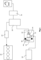
Figur 1 zeigt eine Seitenansicht eines erfindungsgemäßen Kraftstoffdampfschalt- und -lüftungsventils mit schematisch dargestellten angeschlossenen Komponenten. -
Figur 2 zeigt eine Seitenansicht des erfindungsgemäßen Kraftstoffdampfschalt- und -lüftungsventils ausFigur 1 in geschnittener Darstellung. - Wie in
Figur 1 dargestellt ist, weist das erfindungsgemäße Kraftstoffdampfschalt- und -lüftungsventil 10 einen ersten Anschluss 12 auf, der seitlich aus einem Gehäuse 14 des Kraftstoffdampfschalt- und -lüftungsventils 10 ragt und einen zweiten axialen Anschluss 16 auf. Der erste, seitliche Anschluss 12 ist mit einem Kraftstofftank 18 verbunden, während der zweite axiale Anschluss 16 mit einem Aktivkohlefilter 20 verbunden ist. Vom Aktivkohlefilter 20 führt eine Leitung über ein Kraftstoffdampfauslassventil 22 zur Atmosphäre oder über eine zweite Leitung, in der ein Spülventil 24 angeordnet ist zu einer Verbrennungskraftmaschine 26, wo die Kraftstoffdämpfe der Verbrennung zugeführt werden können. - Der Aufbau des Kraftstoffdampfschalt- und -lüftungsventils 10 ist in
Figur 2 zu erkennen. Es besteht aus einem Aktor 28, der als Elektromagnet ausgeführt ist und eine auf einen Spulenträger 30 gewickelte Spule 32, einen innenliegenden Kern 34, einen axial verschiebbaren Anker, der als Betätigungsglied 36 dient, sowie ein die Spule 32 radial umgebendes Joch 38 und jeweils ein an den axialen Enden des Spulenträgers 30 angeordnetes Rückschlussblech 40 aufweist, welche einen elektromagnetischen Kreis bilden. Dieser Aktor 28 und insbesondere das Joch 38 ist zur Bildung eines Aktorgehäuseteils 42 des Gehäuses 14 mit einem Kunststoff umspritzt, welches auch einen Stecker 44 und Befestigungsaugen 46 ausbildet und am zum Kern entgegengesetzten Ende eine axiale Öffnung 48 aufweist, in die eine Gleitbuchse 50 eingeschoben ist, welche das Betätigungsglied 36 führt. Diese Gleitbuchse 50 ist aus einem nicht magnetisierbaren Material und topfförmig ausgebildet, wobei der Boden 52 gegen den Kern 34 anliegt. Der Hauptführungsbereich der Gleitbuchse 50 ist von einer weichmagnetischen Buchse 54 umgeben, welche in das Rückschlussblech 40 und den Spulenträger 30 eingepresst ist. Die Gleitbuchse 50 weist eine radiale Erweiterung 55 auf, von der aus sich an ihrem offenen Ende ein erweiterter Bereich 56 erstreckt, der gegenüberliegend zu den die Öffnung 48 begrenzenden Wandflächen des Aktorgehäuseteils 42 angeordnet ist, wobei zwischen dem erweiterten Bereich 56 der Gleitbuchse 50 und der die Öffnung 48 begrenzende Wandfläche ein Dichtring 58 angeordnet ist, durch den ein Eindringen von Kraftstoffdampf in Richtung der Spule 32 verhindert wird. - Am Aktorgehäuseteil 42 ist ein erstes Strömungsgehäuseteil 60 befestigt, welches den ersten Anschluss 12 ausbildet und in dem ein Ventilkörper 62 bewegbar ist, welcher mit dem als Betätigungsglied 36 dienenden Anker gekoppelt ist, indem am Anker eine Ventilstange 64 befestigt ist, an der der Ventilkörper 62 kardanisch befestigt ist. Die Befestigung der Ventilstange 64 am Betätigungsglied 36 erfolgt, indem die Ventilstange 64 durch eine Durchgangsbohrung 66 im Betätigungsglied 36 geschoben wird bis die Ventilstange 64 mit einer Erweiterung 68 axial gegen das zum Ventilkörper 62 weisende Ende des Betätigungsgliedes 36 anliegt.
- In diesem Zustand ragt die Ventilstange 64 am entgegengesetzten Ende aus dem Betätigungsglied 36 heraus und kann dort umgeformt werden, so dass eine Art Nietkopf 70 in einer kreisringförmigen Ausnehmung 72 an der zum Kern 34 weisenden Seite des Ankers anliegt. An der entgegengesetzten Seite weist die Ventilstange 64 ebenfalls eine Art Nietkopf 74 auf, der in den Ventilkörper 62 ragt, so dass der Ventilkörper 62 ankerseitig gegen das flache Ende des Nietkopfes 74 anliegt, wozu am Ventilkörper 62 eine Öffnung 76 ausgebildet ist, deren Durchmesser im Wesentlichen dem Durchmesser der Ventilstange 64 entspricht. Die runde Seite des Nietkopfes 74 ist gegenüberliegend zu einem radial in das Innere des Ventilkörpers 62 ragenden Vorsprung 78 angeordnet, so dass der Ventilkörper 62 lediglich geringfügig axial relativ zur Ventilstange 64 beweglich ist.
- Ein Federelement 80 spannt den Ventilkörper 62 einerseits gegen die flache Seite des Nietkopfes 74 vor und drückt andererseits den Ventilkörper 62 mit dem Anker 36 gegen einen ersten Ventilsitz 82, der am ersten Strömungsgehäuseteil 60 ausgebildet ist, indem das Federelement 80 zwischen den Ventilkörper 62 und die Erweiterung 55 der Gleitbuchse 50 eingespannt wird.
- Im geschlossenen Zustand liegt der Ventilkörper 62 mit einer ersten, radial äußeren Auflagefläche 84, die als Dichtlippe 85 eines Dichtelementes 86 ausgebildet ist, gegen den ersten Ventilsitz 82 an, der eine Durchströmungsöffnung 87 umgibt. Das Dichtelement 86 besteht aus einem elastischen Material, insbesondere einem Elastomer und ist an einem steifen Trägerelement 88 befestigt, über welches auch die Verbindung zur Ventilstange 64 besteht, so dass der Vorsprung 78 und die Öffnung 76 am Trägerelement 88 ausgebildet sind. Das Trägerelement 88, das aus einem Duroplast, einem Thermoplast oder aus Metall hergestellt ist, deckt das Dichtelement 86 in Richtung des Ankers 36 weitestgehend ab und umgibt dieses auch zumindest teilweise radial mit einem radial äußeren Kragen 89, der zur Befestigung des Dichtelementes 86 am axial äußeren Ende nach radial innen umgeformt wird, so dass das Ende des Kragens 89 axial gegen einen Absatz 91 am Dichtelement 86 anliegt.
- Das Dichtelement 86 weist erfindungsgemäß zusätzlich zur ersten Auflagefläche 84 noch eine weitere radial innerhalb der ersten Auflagefläche 84 platzierte, zweite Auflagefläche 90 auf, die ebenfalls als Dichtlippe 93 ausgeführt ist und axial näher zum Anker 36 angeordnet ist als die erste Auflagefläche 84 und mit der das Dichtelement 86 auf einen zweiten Ventilsitz 92 absenkbar ist. Die Dichtlippen 85, 93 erstrecken sich axial und weisen eine Erstreckungskomponente nach radial innen auf, so dass ein Hinterschnitt entsteht. Entsprechend werden sie bei Auflage auf den Ventilsitzen 82, 92 nach radial innen weiter verformt, so dass einerseits die Elastizität aufgrund des Materials und anderseits aufgrund der Form mit dem Hinterschnitt genutzt werden kann, um einen dichten Verschluss zu erhalten und Unebenheiten oder mangelnde Koaxialitäten ausgleichen zu können.
- Dieser zweite Ventilsitz 92 ist axial bewegbar und an einem Durchflussbegrenzungselement 94 ausgebildet, welches bei Auflage auf der zweiten Auflagefläche 90 eine radial innerhalb der zweiten Auflagefläche 90 ausgebildete Durchlassöffnung 96 am Dichtelement 86 und am Ventilkörper 62 verschließt.
- Das Durchflussbegrenzungselement 94 ist zweiteilig ausgeführt und besteht aus einem Ventilsitzkörper 98, an dem der zweite Ventilsitz 92 ausgebildet ist, und einem Regelkörper 100. Der Ventilsitzkörper 98 weist eine Ventilsitzplatte 99 auf, die sich senkrecht zur Bewegungsachse beziehungsweise Mittelachse des Ventils 10 erstreckt und an deren zum Ventilkörper 62 weisenden Seite der zweite Ventilsitz 92 ausgebildet ist, und von der aus sich ein Befestigungsstift 101 erstreckt, der in einem Sackloch 103 des Regelkörpers 100 befestigt ist. Ein Übergangsbereich 105 zwischen der Ventilsitzplatte 99 und dem Befestigungsstift 101 ist konkav geformt. Des Weiteren weist die Ventilsitzplatte 99 zumindest im Bereich des Ventilsitzes 92 eine axiale Ausdehnung auf, die geringer ist als der axiale Versatz der beiden Auflageflächen 84, 90 am Ventilkörper 62. Dies hat zur Folge, dass die Ventilsitzplatte 99 vollständig axial zwischen den beiden Auflageflächen angeordnet ist, solange der Ventilkörper 62 nicht vom zweiten Ventilsitz 92 abgehoben wird.
- Der Regelkörper 100 weist eine sphärisch geformte Umströmungsfläche 102 auf, welche mit einer Düse 104 korrespondiert, die an einer Innenfläche 106 eines zweiten Strömungsgehäuseteils 108 ausgebildet ist, welches am ersten Strömungsgehäuseteil 60 befestigt ist und den zweiten, axialen Anschluss 16 bildet.
- Das Durchflussbegrenzungselement 94 weist Stege 110 auf, die sich vom Regelkörper 100 nach radial außen erstrecken und die Umströmungsfläche 102 mit einem radial äußeren Ring 112 verbinden. Entsprechend werden zwischen den Stegen 110 sowie zwischen der Umströmungsfläche 102 und dem Ring 112 mehrere Durchlassöffnungen 114 gebildet.
- Das zweite Strömungsgehäuseteil 108 weist einen radial inneren, ringförmigen Vorsprung 116 auf, an dessen Innenseite die Düse 104 ausgebildet ist und dessen axiales Ende als Anschlag 118 für die Bewegung des Durchflussbegrenzungselementes 94 dient, welches bei Anliegen des Rings 112 am Anschlag 118 lediglich einen engen Spalt 120 zwischen der Umströmungsfläche 102 und der Düse 104 freigibt. Das Durchflussbegrenzungselement 94 wird mittels einer Feder 122, die zwischen einer Axialnut 124 des Ringes 112 und einer Auflagefläche 126 am zweiten Strömungsgehäuseteil 108 eingespannt ist, in Richtung des Ventilkörpers 62 und vom Anschlag 118 wegweisend belastet, so dass die Feder 122 den zweiten Ventilsitz 92 gegen den Ventilkörper 62 drückt und den Regelkörper 100 aus dem kleinsten Querschnitt der Düse 104 heraus belastet.
- Die Funktion des Ventils ist nun so, dass im Normalzustand der Ventilkörper 62 mit seinen verformten Dichtlippen 85, 93 auf dem ersten Ventilsitz 82 und dem zweiten Ventilsitz 92 aufliegt und somit keine Durchströmung zwischen den Anschlüssen 12, 16 vorliegt.
- Steigt nun beispielsweise aufgrund von Erwärmung der Druck im Kraftstofftank 18 und damit am ersten Anschluss 12 auf beispielsweise über 0,3 bar Überdruck gegenüber Atmosphäre wird der zweite Ventilsitz 92 durch den auf die Ventilsitzplatte 99 wirkenden Druck von der zweiten Auflagefläche 90 des Ventilkörpers 62 abgehoben, da bei diesem Druck die am Durchflussbegrenzungselement 94 aufgrund der Druckdifferenz wirkenden Kräfte größer sind als die Federkraft der Feder 122. Entsprechend strömt Kraftstoffdampf vom ersten Anschluss 12 über die Durchlassöffnung 96 am Ventilkörper 62 und die Durchströmungsöffnung 87 im Inneren des ersten Ventilsitzes 82 sowie durch die Durchlassöffnungen 114 zwischen den Stegen 110 und dem Spalt 120 zum zweiten Anschluss 16 und damit in Richtung des Aktivkohlefilters 20, so dass der Druck im Kraftstofftank 18 abgebaut wird. Bei sehr großen Drücken, die zu Volumenströmen führen würden, die nicht mehr vom Aktivkohlefilter 20 absorbiert werden können, tritt die Funktion des Durchflussbegrenzungselementes 94 in Kraft. Dieses wird bei sehr hohen Druckunterschieden bis gegen den Anschlag 118 verschoben. In dieser Position wird lediglich ein minimaler Spalt 120 zwischen dem Regelkörper 100 und der Düse 104 freigegeben, der einen maximalen Durchfluss zulässt, der dem maximal zulässigen Durchfluss des Aktivkohlefilters 20 von beispielsweise etwa 220 l/min entspricht. In den anderen Zuständen wird der Durchfluss durch den Spalt in Abhängigkeit der anliegenden Druckdifferenz geändert, also mit fallendem Druck ein größerer Durchströmungsquerschnitt zur Verfügung gestellt.
- Fällt nun beispielweise aufgrund der Tankentleerung der Druck im Kraftstofftank 18 und damit am ersten Anschluss 12 auf beispielsweise unter -0,1 bar Unterdruck gegenüber Atmosphäre wird der Ventilkörper 62 vom ersten Ventilsitz 82 abgehoben, da bei diesem Druck die am Ventilkörper 62 aufgrund der Druckdifferenz wirkenden Kräfte größer sind als die Federkraft des Federelementes 80. Entsprechend strömt Luft vom zweiten Anschluss 16 durch den Spalt 120 zwischen dem Regelkörper 100 und der Düse 104 sowie durch die Durchströmungsöffnung 87 und radial zwischen dem Ventilkörper 62 und dem ersten Ventilsitz 82 zum ersten Anschluss 12, so dass ein Druckausgleich im Tank erfolgt. Der dabei auftretende Strömungswiderstand ist sehr gering, da die Strömung entlang des konkaven Übergangsbereiches 105 allmählich umgelenkt wird und auch die Dichtlippe 85 eine Erstreckung aufweist, die im Wesentlichen der entstehenden Strömungsrichtung entspricht. Die Ventilsitzplatte 99 liegt in diesem Zustand weiter an der zweiten Auflagefläche 90 des Ventilkörpers 62 an, wird also durch die Feder 122 mit in Richtung des Elektromagneten 28 bewegt. Entsprechend befindet sich die Ventilsitzplatte 99 vollständig außerhalb des durchströmten Querschnitts, so dass auch durch die Ventilsitzplatte 99 kein Druckverlust entsteht.
- Des Weiteren ist es durch Bestromung des Elektromagneten 28 möglich, das Kraftstoffdampfschalt- und -lüftungsventil 10 aktiv zu betätigen. Dies erfolgt beispielsweise vor dem Einleiten des Tankvorgangs, um sicherzugehen, dass zu diesem Zeitpunkt keine Über- oder Unterdrücke im Tank 18 vorhanden sind. Dabei wird durch Abheben ein gleicher Zustand des Ventils 10 hergestellt, wie im Fall eines hohen Unterdrucks im Tank 18. Eine Strömung von Luft vom zweiten Anschluss 16 zum ersten Anschluss 12 ist ebenso möglich, wie eine Strömung von Kraftstoffdampf in umgekehrter Richtung, wobei hierbei die Funktion des Durchflussbegrenzungselementes 94 erhalten bleibt. Der Strömungswiderstand bleibt jedoch gering, da die Ventilsitzplatte 99 weiterhin außerhalb des Durchströmungsquerschnitts angeordnet ist.
- Es wird entsprechend ein Kraftstoffdampfschalt- und -lüftungsventil 10 geschaffen, welches zuverlässig sowohl Unter- als auch Überdrücke im Tank 18 abbauen kann und zusätzlich den Durchfluss des Kraftstoffdampfes auf einen maximal zulässigen Wert begrenzt. Auch eine aktive Schaltung ist möglich. Alle diese Funktionen werden in einem kleinbauenden Ventil mit einer minimalen Teileanzahl verwirklicht, da mehrere Funktionen an einem Bauteil verwirklicht werden und durch die geringen Strömungswiderstände und den geringen Druckverlust die vorhandenen Querschnitte relativ klein gehalten werden können, um die notwendigen Volumenströme zu verwirklichen. Zusätzlich entfällt dadurch Gewicht an den zu bewegenden Bauteilen, so dass auch der Aktor kleiner ausgeführt werden kann.
- Es sollte deutlich sein, dass verschiedene Änderungen im Vergleich zum Ausführungsbeispiel möglich sind, ohne den Schutzbereich des Hauptanspruchs zu verlassen. Neben einer unterschiedlichen Ausführung der Gehäusetrennungen kann auch das Durchflussbegrenzungselement oder der Aktor anders ausgeführt werden. Die Schaltpunkte können mit den vorhandenen Federn je nach Anwendung individuell angepasst werden. Gleiches gilt für den maximal zulässigen Durchfluss, der durch konstruktive Änderung der Düse und/oder des Durchflussbegrenzungselementes oder der Ventilglieder und Durchströmungsquerschnitte im Ventil angepasst werden kann.
Claims (13)
- Kraftstoffdampfschalt- und -lüftungsventil (10) für eine Verbrennungskraftmaschine (26) miteinem Aktor (28),einem ersten Anschluss (12) und einem zweiten Anschluss (16),einem Ventilkörper (62), der mit einem axial bewegbaren Betätigungsglied (36) des Aktors (28) gekoppelt ist und eine erste Auflagefläche (84) aufweist, mit der der Ventilkörper (62) auf einen ersten Ventilsitz (82) absenkbar und vom ersten Ventilsitz (82) abhebbar ist, der zwischen dem ersten Anschluss (12) und dem zweiten Anschluss (16) angeordnet ist, und eine zweite Auflagefläche (90) aufweist, mit der der Ventilkörper (62) gegen einen zweiten Ventilsitz (92) bewegbar ist, der axial verschiebbar ist und über eine Feder (122) in Richtung zum Ventilkörper (62) belastet ist,dadurch gekennzeichnet, dassdie zweite Auflagefläche (90) radial innerhalb der ersten Auflagefläche (84) angeordnet ist und axial näher zum Aktor (28) angeordnet ist als die erste Auflagefläche (84).
- Kraftstoffdampfschalt- und -lüftungsventil (10) für eine Verbrennungskraftmaschine nach Anspruch 1,
dadurch gekennzeichnet, dass
der Ventilkörper (62) ein Trägerelement (88) aufweist, an dem ein Dichtelement (86) befestigt ist, an dem die erste Auflagefläche (84) und die zweite Auflagefläche (90) ausgebildet sind. - Kraftstoffdampfschalt- und -lüftungsventil (10) für eine Verbrennungskraftmaschine nach Anspruch 2,
dadurch gekennzeichnet, dass
das Dichtelement (86) aus einem Elastomer ist, und das Trägerelement (88) aus einem Duroplast, einem Thermoplast oder einem Metall ist. - Kraftstoffdampfschalt- und -lüftungsventil (10) für eine Verbrennungskraftmaschine nach Anspruch 3,
dadurch gekennzeichnet, dass
das Dichtelement (86) durch Umformen eines radial äußeren Kragens (89) des Trägerelementes (88) am Trägerelement (88) befestigt ist. - Kraftstoffdampfschalt- und -lüftungsventil (10) für eine Verbrennungskraftmaschine nach einem der Ansprüche 2 bis 4,
dadurch gekennzeichnet, dass
die beiden Auflageflächen (84, 90) des Dichtelementes (86) als Dichtlippen (85, 93) ausgebildet sind, die sich vom Dichtelement (86) zumindest axial in Richtung des jeweiligen Ventilsitzes (82, 92) erstrecken. - Kraftstoffdampfschalt- und -lüftungsventil (10) für eine Verbrennungskraftmaschine nach Anspruch 5,
dadurch gekennzeichnet, dass
die Dichtlippen (85, 93) eine Erstreckungskomponente in axialer Richtung und eine Erstreckungskomponente nach radial innen aufweisen. - Kraftstoffdampfschalt- und -lüftungsventil (10) für eine Verbrennungskraftmaschine nach einem der vorhergehenden Ansprüche,
dadurch gekennzeichnet, dass
der zweite Ventilsitz (92) an einer sich senkrecht zur Mittelachse erstreckenden Ventilsitzplatte (99) eines Ventilsitzkörpers (98) ausgebildet ist. - Kraftstoffdampfschalt- und -lüftungsventil (10) für eine Verbrennungskraftmaschine nach Anspruch 7,
dadurch gekennzeichnet, dass
die Ventilsitzplatte (99) in ihrem den Ventilsitz (92) bildenden Bereich eine geringere axiale Ausdehnung aufweist als der axiale Abstand der beiden Auflageflächen (84, 90) des Dichtelementes (86) zueinander. - Kraftstoffdampfschalt- und -lüftungsventil (10) für eine Verbrennungskraftmaschine nach Anspruch 7 oder 8,
dadurch gekennzeichnet, dass
die Ventilsitzplatte (99) über einen Befestigungsstift (101) an einem Regelkörper (100) befestigt ist, der ein zentrales Sackloch (103) aufweist, in welches sich der Befestigungsstift (101) des Ventilsitzkörpers (98) zur Befestigung des Regelkörpers (100) am Ventilsitzkörper (98) erstreckt. - Kraftstoffdampfschalt- und -lüftungsventil (10) für eine Verbrennungskraftmaschine nach Anspruch 9,
dadurch gekennzeichnet, dass
der Ventilsitzkörper (98) in einem Übergangsbereich (105) zwischen der Ventilsitzplatte (99) und dem Befestigungsstift (101) konkav geformt ist. - Kraftstoffdampfschalt- und -lüftungsventil (10) für eine Verbrennungskraftmaschine nach einem der vorherigen Ansprüche,
dadurch gekennzeichnet, dass
am Ventilkörper (62) eine Durchlassöffnung (96) ausgebildet ist, die radial innerhalb der zweiten Auflagefläche (90) mündet. - Kraftstoffdampfschalt- und -lüftungsventil (10) für eine Verbrennungskraftmaschine nach einem der Ansprüche 2 bis 11,
dadurch gekennzeichnet, dass
der Ventilkörper (62) über das Trägerelement (88) kardanisch an einer Ventilstange (64) befestigt ist, die mit dem Betätigungsglied (36) verbunden ist. - Kraftstoffdampfschalt- und -lüftungsventil (10) für eine Verbrennungskraftmaschine nach einem der Ansprüche 9 bis 12,
dadurch gekennzeichnet, dass
der Regelkörper (100) als Durchflussbegrenzungselement (94) dient, welches in eine Düse (104) bewegbar ist, die in einem Strömungsgehäuseteil (108) des zweiten Anschlusses (16) angeordnet ist, wobei die Feder (122) das Durchflussbegrenzungselement (94) in einer aus der Düse (104) heraus weisenden Richtung belastet.
Applications Claiming Priority (1)
| Application Number | Priority Date | Filing Date | Title |
|---|---|---|---|
| PCT/EP2020/062935 WO2021223891A1 (de) | 2020-05-08 | 2020-05-08 | Kraftstoffdampfschalt- und -lüftungsventil für eine verbrennungskraftmaschine |
Publications (2)
| Publication Number | Publication Date |
|---|---|
| EP4146964A1 EP4146964A1 (de) | 2023-03-15 |
| EP4146964B1 true EP4146964B1 (de) | 2024-10-02 |
Family
ID=70857141
Family Applications (1)
| Application Number | Title | Priority Date | Filing Date |
|---|---|---|---|
| EP20728413.4A Active EP4146964B1 (de) | 2020-05-08 | 2020-05-08 | Kraftstoffdampfschalt- und -lüftungsventil für eine verbrennungskraftmaschine |
Country Status (2)
| Country | Link |
|---|---|
| EP (1) | EP4146964B1 (de) |
| WO (1) | WO2021223891A1 (de) |
Families Citing this family (1)
| Publication number | Priority date | Publication date | Assignee | Title |
|---|---|---|---|---|
| CN120062370A (zh) * | 2025-04-28 | 2025-05-30 | 富临精工股份有限公司 | 电磁阀 |
Citations (1)
| Publication number | Priority date | Publication date | Assignee | Title |
|---|---|---|---|---|
| DE102010044336A1 (de) * | 2010-09-03 | 2012-03-08 | A. Kayser Automotive Systems Gmbh | Entlüftungsanordnung für einen Kraftstofftank |
Family Cites Families (4)
| Publication number | Priority date | Publication date | Assignee | Title |
|---|---|---|---|---|
| US3414232A (en) * | 1966-08-08 | 1968-12-03 | Westport Dev & Mfg Company Inc | Gimbal valve |
| US6651953B2 (en) * | 2000-08-08 | 2003-11-25 | Siemens Automotive Inc. | Fuel tank pressure control valve including an in-line flow-through construction |
| US20160123490A1 (en) * | 2009-04-22 | 2016-05-05 | Eaton Corporation | Overmolded valve assembly |
| US10458366B2 (en) * | 2016-10-31 | 2019-10-29 | Stant Usa Corp. | Fuel tank pressure regulator |
-
2020
- 2020-05-08 EP EP20728413.4A patent/EP4146964B1/de active Active
- 2020-05-08 WO PCT/EP2020/062935 patent/WO2021223891A1/de not_active Ceased
Patent Citations (1)
| Publication number | Priority date | Publication date | Assignee | Title |
|---|---|---|---|---|
| DE102010044336A1 (de) * | 2010-09-03 | 2012-03-08 | A. Kayser Automotive Systems Gmbh | Entlüftungsanordnung für einen Kraftstofftank |
Also Published As
| Publication number | Publication date |
|---|---|
| WO2021223891A1 (de) | 2021-11-11 |
| EP4146964A1 (de) | 2023-03-15 |
Similar Documents
| Publication | Publication Date | Title |
|---|---|---|
| DE102010044336A1 (de) | Entlüftungsanordnung für einen Kraftstofftank | |
| EP0400395A2 (de) | Stossdämpfer | |
| EP0681128A1 (de) | Magnetventil | |
| DE102020203700A1 (de) | Ventilvorrichtung für ein Brennstoffzellensystem und Tankvorrichtung zur Speicherung eines gasförmigen Mediums | |
| WO2021052560A1 (de) | Elektromagnetventil für ein kraftfahrzeug und verfahren zur herstellung einer bewegungseinheit aus einem anker und einer ventileinheit für ein derartiges elektromagnetventil | |
| DE102011089951A1 (de) | Hydraulisch gesteuertes Speicherkammerventil | |
| EP1373704A1 (de) | Magnetventil | |
| DE102010025171A1 (de) | Fluiddruckumschaltventil | |
| EP4146964B1 (de) | Kraftstoffdampfschalt- und -lüftungsventil für eine verbrennungskraftmaschine | |
| DE10161995A1 (de) | Magnetventil | |
| EP3556621B1 (de) | Druckbegrenzungsventil | |
| EP4146963B1 (de) | Kraftstoffdampfschalt- und -lüftungsventil für eine verbrennungskraftmaschine | |
| WO2021223890A1 (de) | Kraftstoffdampfschalt- und -lüftungsventil für eine verbrennungskraftmaschine | |
| WO2021223994A1 (de) | Elektromagnetventil zur belüftung und entgasung eines kraftstofftanks einer verbrennungskraftmaschine | |
| EP4139596B1 (de) | Schubumluftventil | |
| EP2833043A1 (de) | Ventileinrichtung | |
| EP4423422A1 (de) | Absperrventil sowie wasserstofftanksystem mit absperrventil | |
| DE102020115850B4 (de) | Durchflussbegrenzungselement für ein Kraftstoffdampfschalt- und -lüftungsventil einer Verbrennungskraftmaschine | |
| WO2022161596A1 (de) | Durchflussbegrenzungselement für ein kraftstoffdampfschalt- und -lüftungsventil einer verbrennungskraftmaschine | |
| WO2021223888A1 (de) | Durchflussbegrenzungselement für ein kraftstoffdampfschalt- und -lüftungsventil einer verbrennungskraftmaschine | |
| DE102020212948A1 (de) | Magnetventil für einen Druckgasbehälter, Druckgasbehälter mit Magnetventil | |
| DE102022123317B4 (de) | Magnetventil | |
| EP1208297A1 (de) | Einspritzventil für eine verbrennungskraftmaschine | |
| DE102022202170A1 (de) | Absperrventil sowie Wasserstofftanksystem mit Absperrventil | |
| DE102024202948A1 (de) | Sicherheitsmagnetventileinrichtung und Verfahren zum Betreiben einer Sicherheitsmagnetventileinrichtung |
Legal Events
| Date | Code | Title | Description |
|---|---|---|---|
| STAA | Information on the status of an ep patent application or granted ep patent |
Free format text: STATUS: UNKNOWN |
|
| STAA | Information on the status of an ep patent application or granted ep patent |
Free format text: STATUS: THE INTERNATIONAL PUBLICATION HAS BEEN MADE |
|
| PUAI | Public reference made under article 153(3) epc to a published international application that has entered the european phase |
Free format text: ORIGINAL CODE: 0009012 |
|
| STAA | Information on the status of an ep patent application or granted ep patent |
Free format text: STATUS: REQUEST FOR EXAMINATION WAS MADE |
|
| 17P | Request for examination filed |
Effective date: 20221116 |
|
| AK | Designated contracting states |
Kind code of ref document: A1 Designated state(s): AL AT BE BG CH CY CZ DE DK EE ES FI FR GB GR HR HU IE IS IT LI LT LU LV MC MK MT NL NO PL PT RO RS SE SI SK SM TR |
|
| DAV | Request for validation of the european patent (deleted) | ||
| DAX | Request for extension of the european patent (deleted) | ||
| REG | Reference to a national code |
Ref legal event code: R079 Ref country code: DE Ref legal event code: R079 Ref document number: 502020009372 Country of ref document: DE Free format text: PREVIOUS MAIN CLASS: F16K0017196000 Ipc: B60K0015035000 |
|
| GRAP | Despatch of communication of intention to grant a patent |
Free format text: ORIGINAL CODE: EPIDOSNIGR1 |
|
| STAA | Information on the status of an ep patent application or granted ep patent |
Free format text: STATUS: GRANT OF PATENT IS INTENDED |
|
| RIC1 | Information provided on ipc code assigned before grant |
Ipc: F16K 17/196 20060101ALI20240521BHEP Ipc: B60K 15/03 20060101ALI20240521BHEP Ipc: F16K 24/00 20060101ALI20240521BHEP Ipc: F16K 31/06 20060101ALI20240521BHEP Ipc: F16K 1/52 20060101ALI20240521BHEP Ipc: F16K 1/44 20060101ALI20240521BHEP Ipc: B60K 15/035 20060101AFI20240521BHEP |
|
| INTG | Intention to grant announced |
Effective date: 20240606 |
|
| GRAS | Grant fee paid |
Free format text: ORIGINAL CODE: EPIDOSNIGR3 |
|
| GRAA | (expected) grant |
Free format text: ORIGINAL CODE: 0009210 |
|
| STAA | Information on the status of an ep patent application or granted ep patent |
Free format text: STATUS: THE PATENT HAS BEEN GRANTED |
|
| AK | Designated contracting states |
Kind code of ref document: B1 Designated state(s): AL AT BE BG CH CY CZ DE DK EE ES FI FR GB GR HR HU IE IS IT LI LT LU LV MC MK MT NL NO PL PT RO RS SE SI SK SM TR |
|
| REG | Reference to a national code |
Ref country code: GB Ref legal event code: FG4D Free format text: NOT ENGLISH |
|
| REG | Reference to a national code |
Ref country code: CH Ref legal event code: EP |
|
| REG | Reference to a national code |
Ref country code: DE Ref legal event code: R096 Ref document number: 502020009372 Country of ref document: DE |
|
| REG | Reference to a national code |
Ref country code: IE Ref legal event code: FG4D Free format text: LANGUAGE OF EP DOCUMENT: GERMAN |
|
| REG | Reference to a national code |
Ref country code: LT Ref legal event code: MG9D |
|
| REG | Reference to a national code |
Ref country code: NL Ref legal event code: MP Effective date: 20241002 |
|
| PG25 | Lapsed in a contracting state [announced via postgrant information from national office to epo] |
Ref country code: NL Free format text: LAPSE BECAUSE OF FAILURE TO SUBMIT A TRANSLATION OF THE DESCRIPTION OR TO PAY THE FEE WITHIN THE PRESCRIBED TIME-LIMIT Effective date: 20241002 |
|
| PG25 | Lapsed in a contracting state [announced via postgrant information from national office to epo] |
Ref country code: NL Free format text: LAPSE BECAUSE OF FAILURE TO SUBMIT A TRANSLATION OF THE DESCRIPTION OR TO PAY THE FEE WITHIN THE PRESCRIBED TIME-LIMIT Effective date: 20241002 |
|
| PG25 | Lapsed in a contracting state [announced via postgrant information from national office to epo] |
Ref country code: PT Free format text: LAPSE BECAUSE OF FAILURE TO SUBMIT A TRANSLATION OF THE DESCRIPTION OR TO PAY THE FEE WITHIN THE PRESCRIBED TIME-LIMIT Effective date: 20250203 Ref country code: IS Free format text: LAPSE BECAUSE OF FAILURE TO SUBMIT A TRANSLATION OF THE DESCRIPTION OR TO PAY THE FEE WITHIN THE PRESCRIBED TIME-LIMIT Effective date: 20250202 Ref country code: HR Free format text: LAPSE BECAUSE OF FAILURE TO SUBMIT A TRANSLATION OF THE DESCRIPTION OR TO PAY THE FEE WITHIN THE PRESCRIBED TIME-LIMIT Effective date: 20241002 |
|
| PG25 | Lapsed in a contracting state [announced via postgrant information from national office to epo] |
Ref country code: FI Free format text: LAPSE BECAUSE OF FAILURE TO SUBMIT A TRANSLATION OF THE DESCRIPTION OR TO PAY THE FEE WITHIN THE PRESCRIBED TIME-LIMIT Effective date: 20241002 |
|
| PG25 | Lapsed in a contracting state [announced via postgrant information from national office to epo] |
Ref country code: BG Free format text: LAPSE BECAUSE OF FAILURE TO SUBMIT A TRANSLATION OF THE DESCRIPTION OR TO PAY THE FEE WITHIN THE PRESCRIBED TIME-LIMIT Effective date: 20241002 |
|
| PG25 | Lapsed in a contracting state [announced via postgrant information from national office to epo] |
Ref country code: ES Free format text: LAPSE BECAUSE OF FAILURE TO SUBMIT A TRANSLATION OF THE DESCRIPTION OR TO PAY THE FEE WITHIN THE PRESCRIBED TIME-LIMIT Effective date: 20241002 |
|
| PG25 | Lapsed in a contracting state [announced via postgrant information from national office to epo] |
Ref country code: NO Free format text: LAPSE BECAUSE OF FAILURE TO SUBMIT A TRANSLATION OF THE DESCRIPTION OR TO PAY THE FEE WITHIN THE PRESCRIBED TIME-LIMIT Effective date: 20250102 |
|
| PG25 | Lapsed in a contracting state [announced via postgrant information from national office to epo] |
Ref country code: GR Free format text: LAPSE BECAUSE OF FAILURE TO SUBMIT A TRANSLATION OF THE DESCRIPTION OR TO PAY THE FEE WITHIN THE PRESCRIBED TIME-LIMIT Effective date: 20250103 Ref country code: LV Free format text: LAPSE BECAUSE OF FAILURE TO SUBMIT A TRANSLATION OF THE DESCRIPTION OR TO PAY THE FEE WITHIN THE PRESCRIBED TIME-LIMIT Effective date: 20241002 |
|
| PG25 | Lapsed in a contracting state [announced via postgrant information from national office to epo] |
Ref country code: CZ Free format text: LAPSE BECAUSE OF FAILURE TO SUBMIT A TRANSLATION OF THE DESCRIPTION OR TO PAY THE FEE WITHIN THE PRESCRIBED TIME-LIMIT Effective date: 20241002 Ref country code: PL Free format text: LAPSE BECAUSE OF FAILURE TO SUBMIT A TRANSLATION OF THE DESCRIPTION OR TO PAY THE FEE WITHIN THE PRESCRIBED TIME-LIMIT Effective date: 20241002 |
|
| PG25 | Lapsed in a contracting state [announced via postgrant information from national office to epo] |
Ref country code: RS Free format text: LAPSE BECAUSE OF FAILURE TO SUBMIT A TRANSLATION OF THE DESCRIPTION OR TO PAY THE FEE WITHIN THE PRESCRIBED TIME-LIMIT Effective date: 20250102 |
|
| PG25 | Lapsed in a contracting state [announced via postgrant information from national office to epo] |
Ref country code: SM Free format text: LAPSE BECAUSE OF FAILURE TO SUBMIT A TRANSLATION OF THE DESCRIPTION OR TO PAY THE FEE WITHIN THE PRESCRIBED TIME-LIMIT Effective date: 20241002 |
|
| REG | Reference to a national code |
Ref country code: DE Ref legal event code: R097 Ref document number: 502020009372 Country of ref document: DE |
|
| PGFP | Annual fee paid to national office [announced via postgrant information from national office to epo] |
Ref country code: DE Payment date: 20250521 Year of fee payment: 6 |
|
| PG25 | Lapsed in a contracting state [announced via postgrant information from national office to epo] |
Ref country code: DK Free format text: LAPSE BECAUSE OF FAILURE TO SUBMIT A TRANSLATION OF THE DESCRIPTION OR TO PAY THE FEE WITHIN THE PRESCRIBED TIME-LIMIT Effective date: 20241002 |
|
| PGFP | Annual fee paid to national office [announced via postgrant information from national office to epo] |
Ref country code: GB Payment date: 20250527 Year of fee payment: 6 |
|
| PG25 | Lapsed in a contracting state [announced via postgrant information from national office to epo] |
Ref country code: EE Free format text: LAPSE BECAUSE OF FAILURE TO SUBMIT A TRANSLATION OF THE DESCRIPTION OR TO PAY THE FEE WITHIN THE PRESCRIBED TIME-LIMIT Effective date: 20241002 |
|
| PGFP | Annual fee paid to national office [announced via postgrant information from national office to epo] |
Ref country code: FR Payment date: 20250528 Year of fee payment: 6 |
|
| PG25 | Lapsed in a contracting state [announced via postgrant information from national office to epo] |
Ref country code: RO Free format text: LAPSE BECAUSE OF FAILURE TO SUBMIT A TRANSLATION OF THE DESCRIPTION OR TO PAY THE FEE WITHIN THE PRESCRIBED TIME-LIMIT Effective date: 20241002 |
|
| PG25 | Lapsed in a contracting state [announced via postgrant information from national office to epo] |
Ref country code: SK Free format text: LAPSE BECAUSE OF FAILURE TO SUBMIT A TRANSLATION OF THE DESCRIPTION OR TO PAY THE FEE WITHIN THE PRESCRIBED TIME-LIMIT Effective date: 20241002 |
|
| PG25 | Lapsed in a contracting state [announced via postgrant information from national office to epo] |
Ref country code: IT Free format text: LAPSE BECAUSE OF FAILURE TO SUBMIT A TRANSLATION OF THE DESCRIPTION OR TO PAY THE FEE WITHIN THE PRESCRIBED TIME-LIMIT Effective date: 20241002 |
|
| PLBE | No opposition filed within time limit |
Free format text: ORIGINAL CODE: 0009261 |
|
| STAA | Information on the status of an ep patent application or granted ep patent |
Free format text: STATUS: NO OPPOSITION FILED WITHIN TIME LIMIT |
|
| PG25 | Lapsed in a contracting state [announced via postgrant information from national office to epo] |
Ref country code: SE Free format text: LAPSE BECAUSE OF FAILURE TO SUBMIT A TRANSLATION OF THE DESCRIPTION OR TO PAY THE FEE WITHIN THE PRESCRIBED TIME-LIMIT Effective date: 20241002 |
|
| 26N | No opposition filed |
Effective date: 20250703 |
|
| REG | Reference to a national code |
Ref country code: CH Ref legal event code: H13 Free format text: ST27 STATUS EVENT CODE: U-0-0-H10-H13 (AS PROVIDED BY THE NATIONAL OFFICE) Effective date: 20251223 |
|
| PG25 | Lapsed in a contracting state [announced via postgrant information from national office to epo] |
Ref country code: LU Free format text: LAPSE BECAUSE OF NON-PAYMENT OF DUE FEES Effective date: 20250508 |
|
| PG25 | Lapsed in a contracting state [announced via postgrant information from national office to epo] |
Ref country code: CH Free format text: LAPSE BECAUSE OF NON-PAYMENT OF DUE FEES Effective date: 20250531 |
|
| REG | Reference to a national code |
Ref country code: BE Ref legal event code: MM Effective date: 20250531 |
|
| PG25 | Lapsed in a contracting state [announced via postgrant information from national office to epo] |
Ref country code: MC Free format text: LAPSE BECAUSE OF FAILURE TO SUBMIT A TRANSLATION OF THE DESCRIPTION OR TO PAY THE FEE WITHIN THE PRESCRIBED TIME-LIMIT Effective date: 20241002 |
|
| REG | Reference to a national code |
Ref country code: DE Ref legal event code: R082 Ref document number: 502020009372 Country of ref document: DE |
|
| PG25 | Lapsed in a contracting state [announced via postgrant information from national office to epo] |
Ref country code: IE Free format text: LAPSE BECAUSE OF NON-PAYMENT OF DUE FEES Effective date: 20250508 |
|
| PG25 | Lapsed in a contracting state [announced via postgrant information from national office to epo] |
Ref country code: BE Free format text: LAPSE BECAUSE OF NON-PAYMENT OF DUE FEES Effective date: 20250531 |