EP4146928B1 - Hydrodynamischer turbinenrotor - Google Patents
Hydrodynamischer turbinenrotor Download PDFInfo
- Publication number
- EP4146928B1 EP4146928B1 EP21726981.0A EP21726981A EP4146928B1 EP 4146928 B1 EP4146928 B1 EP 4146928B1 EP 21726981 A EP21726981 A EP 21726981A EP 4146928 B1 EP4146928 B1 EP 4146928B1
- Authority
- EP
- European Patent Office
- Prior art keywords
- blade
- rotation shaft
- connection system
- module
- blade module
- Prior art date
- Legal status (The legal status is an assumption and is not a legal conclusion. Google has not performed a legal analysis and makes no representation as to the accuracy of the status listed.)
- Active
Links
Images



Classifications
-
- F—MECHANICAL ENGINEERING; LIGHTING; HEATING; WEAPONS; BLASTING
- F03—MACHINES OR ENGINES FOR LIQUIDS; WIND, SPRING, OR WEIGHT MOTORS; PRODUCING MECHANICAL POWER OR A REACTIVE PROPULSIVE THRUST, NOT OTHERWISE PROVIDED FOR
- F03B—MACHINES OR ENGINES FOR LIQUIDS
- F03B17/00—Other machines or engines
- F03B17/06—Other machines or engines using liquid flow with predominantly kinetic energy conversion, e.g. of swinging-flap type, "run-of-river", "ultra-low head"
- F03B17/062—Other machines or engines using liquid flow with predominantly kinetic energy conversion, e.g. of swinging-flap type, "run-of-river", "ultra-low head" with rotation axis substantially at right angle to flow direction
- F03B17/063—Other machines or engines using liquid flow with predominantly kinetic energy conversion, e.g. of swinging-flap type, "run-of-river", "ultra-low head" with rotation axis substantially at right angle to flow direction the flow engaging parts having no movement relative to the rotor during its rotation
-
- F—MECHANICAL ENGINEERING; LIGHTING; HEATING; WEAPONS; BLASTING
- F03—MACHINES OR ENGINES FOR LIQUIDS; WIND, SPRING, OR WEIGHT MOTORS; PRODUCING MECHANICAL POWER OR A REACTIVE PROPULSIVE THRUST, NOT OTHERWISE PROVIDED FOR
- F03D—WIND MOTORS
- F03D3/00—Wind motors with rotation axis substantially perpendicular to the air flow entering the rotor
- F03D3/06—Rotors
- F03D3/062—Rotors characterised by their construction elements
- F03D3/064—Fixing wind engaging parts to rest of rotor
-
- F—MECHANICAL ENGINEERING; LIGHTING; HEATING; WEAPONS; BLASTING
- F05—INDEXING SCHEMES RELATING TO ENGINES OR PUMPS IN VARIOUS SUBCLASSES OF CLASSES F01-F04
- F05B—INDEXING SCHEME RELATING TO WIND, SPRING, WEIGHT, INERTIA OR LIKE MOTORS, TO MACHINES OR ENGINES FOR LIQUIDS COVERED BY SUBCLASSES F03B, F03D AND F03G
- F05B2230/00—Manufacture
- F05B2230/60—Assembly methods
-
- F—MECHANICAL ENGINEERING; LIGHTING; HEATING; WEAPONS; BLASTING
- F05—INDEXING SCHEMES RELATING TO ENGINES OR PUMPS IN VARIOUS SUBCLASSES OF CLASSES F01-F04
- F05B—INDEXING SCHEME RELATING TO WIND, SPRING, WEIGHT, INERTIA OR LIKE MOTORS, TO MACHINES OR ENGINES FOR LIQUIDS COVERED BY SUBCLASSES F03B, F03D AND F03G
- F05B2240/00—Components
- F05B2240/20—Rotors
- F05B2240/30—Characteristics of rotor blades, i.e. of any element transforming dynamic fluid energy to or from rotational energy and being attached to a rotor
- F05B2240/301—Cross-section characteristics
-
- F—MECHANICAL ENGINEERING; LIGHTING; HEATING; WEAPONS; BLASTING
- F05—INDEXING SCHEMES RELATING TO ENGINES OR PUMPS IN VARIOUS SUBCLASSES OF CLASSES F01-F04
- F05B—INDEXING SCHEME RELATING TO WIND, SPRING, WEIGHT, INERTIA OR LIKE MOTORS, TO MACHINES OR ENGINES FOR LIQUIDS COVERED BY SUBCLASSES F03B, F03D AND F03G
- F05B2240/00—Components
- F05B2240/20—Rotors
- F05B2240/30—Characteristics of rotor blades, i.e. of any element transforming dynamic fluid energy to or from rotational energy and being attached to a rotor
- F05B2240/302—Segmented or sectional blades
-
- F—MECHANICAL ENGINEERING; LIGHTING; HEATING; WEAPONS; BLASTING
- F05—INDEXING SCHEMES RELATING TO ENGINES OR PUMPS IN VARIOUS SUBCLASSES OF CLASSES F01-F04
- F05B—INDEXING SCHEME RELATING TO WIND, SPRING, WEIGHT, INERTIA OR LIKE MOTORS, TO MACHINES OR ENGINES FOR LIQUIDS COVERED BY SUBCLASSES F03B, F03D AND F03G
- F05B2240/00—Components
- F05B2240/20—Rotors
- F05B2240/37—Multiple rotors
- F05B2240/372—Multiple rotors coaxially arranged
-
- F—MECHANICAL ENGINEERING; LIGHTING; HEATING; WEAPONS; BLASTING
- F05—INDEXING SCHEMES RELATING TO ENGINES OR PUMPS IN VARIOUS SUBCLASSES OF CLASSES F01-F04
- F05B—INDEXING SCHEME RELATING TO WIND, SPRING, WEIGHT, INERTIA OR LIKE MOTORS, TO MACHINES OR ENGINES FOR LIQUIDS COVERED BY SUBCLASSES F03B, F03D AND F03G
- F05B2260/00—Function
- F05B2260/30—Retaining components in desired mutual position
-
- Y—GENERAL TAGGING OF NEW TECHNOLOGICAL DEVELOPMENTS; GENERAL TAGGING OF CROSS-SECTIONAL TECHNOLOGIES SPANNING OVER SEVERAL SECTIONS OF THE IPC; TECHNICAL SUBJECTS COVERED BY FORMER USPC CROSS-REFERENCE ART COLLECTIONS [XRACs] AND DIGESTS
- Y02—TECHNOLOGIES OR APPLICATIONS FOR MITIGATION OR ADAPTATION AGAINST CLIMATE CHANGE
- Y02E—REDUCTION OF GREENHOUSE GAS [GHG] EMISSIONS, RELATED TO ENERGY GENERATION, TRANSMISSION OR DISTRIBUTION
- Y02E10/00—Energy generation through renewable energy sources
- Y02E10/20—Hydro energy
-
- Y—GENERAL TAGGING OF NEW TECHNOLOGICAL DEVELOPMENTS; GENERAL TAGGING OF CROSS-SECTIONAL TECHNOLOGIES SPANNING OVER SEVERAL SECTIONS OF THE IPC; TECHNICAL SUBJECTS COVERED BY FORMER USPC CROSS-REFERENCE ART COLLECTIONS [XRACs] AND DIGESTS
- Y02—TECHNOLOGIES OR APPLICATIONS FOR MITIGATION OR ADAPTATION AGAINST CLIMATE CHANGE
- Y02E—REDUCTION OF GREENHOUSE GAS [GHG] EMISSIONS, RELATED TO ENERGY GENERATION, TRANSMISSION OR DISTRIBUTION
- Y02E10/00—Energy generation through renewable energy sources
- Y02E10/30—Energy from the sea, e.g. using wave energy or salinity gradient
-
- Y—GENERAL TAGGING OF NEW TECHNOLOGICAL DEVELOPMENTS; GENERAL TAGGING OF CROSS-SECTIONAL TECHNOLOGIES SPANNING OVER SEVERAL SECTIONS OF THE IPC; TECHNICAL SUBJECTS COVERED BY FORMER USPC CROSS-REFERENCE ART COLLECTIONS [XRACs] AND DIGESTS
- Y02—TECHNOLOGIES OR APPLICATIONS FOR MITIGATION OR ADAPTATION AGAINST CLIMATE CHANGE
- Y02P—CLIMATE CHANGE MITIGATION TECHNOLOGIES IN THE PRODUCTION OR PROCESSING OF GOODS
- Y02P70/00—Climate change mitigation technologies in the production process for final industrial or consumer products
- Y02P70/50—Manufacturing or production processes characterised by the final manufactured product
Definitions
- the present invention relates, in general, to the field of electric energy production.
- the present invention relates to a hydrodynamic turbine.
- Green Deal a gradual reduction in environmentally harmful emissions until climate neutrality is achieved by 2050.
- hydroelectric energy As is known, one of the most used renewable sources is hydroelectric energy.
- Hydroelectric energy is an energy source obtained, for example, by exploiting the water flow of a river and/or an artificial channel, which is suitably conveyed towards a hydrodynamic turbine. Said hydrodynamic turbine transforms the kinetic energy of the water flow into electric energy.
- each section may be characterized by different geometries of the wet perimeter and different local speeds of the water flow.
- each section of a watercourse may require turbines having a different diameter, height and/or number of blades.
- the Applicant has noted that designing and manufacturing a specific rotor in order to optimize the production of electric energy and/or the specific cost per kilowatt-hour result in increased production costs.
- the present invention aims at providing a hydrodynamic turbine according to claim 1.
- a hydrodynamic turbine 100 comprising:
- the rotation shaft 30 extends longitudinally and has a first portion and a second portion.
- the first portion of the rotation shaft 30 is coupled to the rotor 40; the second portion of the rotation shaft 30 is coupled to the electric energy generator 10.
- the rotor 40 comprises a first connection system 41 and a second connection system 42.
- first connection system 41 and the second connection system 42 are integrally engaged with the rotation shaft 30.
- the rotor 40 comprises a first blade module 50.
- the first blade module 50 comprises at least two blades 51a, 51b.
- Each blade 51a, 51b of the first blade module 50 is equipped with a first end and a second end.
- each blade 51a, 51b of the first blade module 50 comprises a respective inner cavity 73 having a substantially rectangular cross-section.
- each connection system 41, 42 comprises a plurality of elongate engagement elements 84, 92.
- Each elongate engagement element 84, 92 has a substantially rectangular cross-section.
- each blade 51a, 51b of the first blade module 50 has a substantially rectangular cross-section with radiused angles.
- each elongate engagement element 84, 92 has a substantially rectangular cross-section with radiused angles.
- each elongate engagement element 84, 92 is coupled to the cavity 73 of a respective blade 51a, 51b of the first blade module 50.
- each blade 51a, 51b of the first blade module 50 is coupled, at a first end thereof, to the first connection system 41 and, at a second end thereof, to the second connection system 42.
- the rotor 40 comprises a third connection system 43.
- the third connection system 43 is integrally engaged with the rotation shaft 30.
- the rotor 40 comprises a second blade module 60.
- the second blade module 60 comprises at least two blades 61a, 61b.
- each blade 61a, 61b of the second blade module 60 is equipped with a first end and a second end.
- Each blade 61a, 61b of the second blade module 60 comprises a respective inner cavity 73 having a substantially rectangular cross-section; preferably, such respective inner cavity 73 has radiused angles.
- the third connection system 43 comprises a plurality of elongate engagement elements 84, 92 having a substantially rectangular cross-section.
- such elongate engagement element 84, 92 of the third connection system 43 have a substantially rectangular cross-section with radiused angles.
- each elongate engagement element 84, 92 of the third connection system is coupled to the cavity 73 of a respective blade 61a, 61b of the second blade module 60.
- each blade 61a, 61b of the second blade module 60 is coupled, at a first end thereof, to the second connection system 42 and, at a second end thereof, to the third connection system 43.
- the first connection system 41, the second connection system 42 and the third connection system 43 are positioned on the rotation shaft 30 at a predetermined distance.
- the distance between the first connection system 41 and the second connection system 42 is preferably equal to the distance between the second connection system 42 and the third connection system 43 when they are engaged with the rotation shaft 30.
- the rotor 40 comprises: the first blade 51a; the second blade 51b; the first connection system 41; and the second connection system 42.
- first connection system 41 is positioned along the rotation shaft 30; the second connection system 42 is positioned at the free end of the rotation shaft 30.
- first blade 51a and the second blade 51b are coupled to the first connection system 41 and to the second connection system 42, and are positioned in such a way as to form an angle of 180° between themselves.
- the rotor 40 further comprises a third blade 51c.
- the third blade 51c is coupled to the first connection system 41 and to the second connection system 42.
- first blade 51a, the second blade 51b and the third blade 51c are coupled to the first and second connection systems 41, 42 in such a way as to form an angle of 120° between two adjacent blades.
- first blade 51a, the second blade 51b and the third blade 51c are so arranged as to form a mutual angle of 120°.
- the rotor 40 comprises:
- the first blade module 50 comprises two blades 51a, 51b; the second blade module 60 comprises two blades 61a, 61b.
- the two blades 51a, 51b of the first blade module 50 are coupled, at a first end thereof (i.e. the upper end) to the first connection system 41 and, at a second end thereof (i.e. the lower end) to the second connection system 42.
- the two blades 61a, 61b of the second blade module 60 are coupled, at a first end thereof (i.e. the upper end) to the second connection system 42 and, at a second end thereof (i.e. the lower end) to the third connection system 43.
- the two blades 51a, 51b of the first blade module 50 and the rotation shaft 30 lie in a first plane X-Z.
- the two blades 61a, 61b of the second blade module 60 and the rotation shaft 30 lie in a second plane Y-Z.
- first plane X-Z and the second plane Y-Z are perpendicular to each other.
- the second blade 51b of the first blade module 50, the first blade 61a of the second blade module 60 and the rotation shaft 30 lie in a third plane Y'-Z'.
- the first blade 51a of the first blade module 50, the second blade 61b of the second blade module 60 and the rotation shaft 30 lie in a fourth plane X'-Z'.
- the third plane Y'-Z' and the fourth plane X'-Z' are perpendicular to each other.
- each blade belonging to the first blade module 50 or to the second blade module 60 will be generally designated by reference numeral 70.
- each blade 70 of at least one of the first blade module 50 and the second blade module 60 preferably comprises, respectively:
- first end of a respective blade 70 corresponds to the free end of the first connection tract 71a; the second end of a respective blade 70 corresponds to the free end of the second connection tract 71b.
- each connection tract 71a, 71b engages a respective connection system 41, 42, 43.
- the main tract 71 has a length of 1 to 4 meters.
- connection tracts 71a, 71b have a length of 0.7 to 2 meters.
- connection tracts 71a, 71b are arranged transversally, and even more preferably perpendicularly, to the rotation shaft 30.
- each blade 70 of the first blade module 50 and/or of the second blade module 60 is equipped with a respective inner cavity 73 having a substantially rectangular cross-section.
- each inner cavity 73 has radiused angles.
- each blade 70 comprises a front cavity 74 and a rear cavity 75.
- the front cavity 74 and the rear cavity 75 have a substantially triangular cross-section.
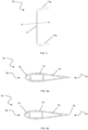
- each blade 70 preferably has a hydrodynamic profile and comprises a head portion 78 and a tail portion 79.
- each blade 70 is equipped with a Gurney flap 79' at its tail portion 79 ( Figure 4b ).
- Such Gurney flaps 79' form an angle of 45° relative to the outer surface of the blade 70.
- each blade 70 of the first blade module 50 and each blade 70 of the second blade module 60 are substantially equal.
- each blade 70 of the first blade module 50 and/or of the second blade module 60 is made as one piece.
- each blade 70 of the first blade module 50 and/or of the second blade module 60 is made by means of an extrusion process.
- a rod (not shown) with a substantially longitudinal development and internally equipped with a cavity (i.e. the above-described inner cavity 73).
- a cavity i.e. the above-described inner cavity 73.
- such rod is also equipped with a cavity with longitudinal development formed in the front part (i.e. the front cavity 74) and a cavity with longitudinal development formed in the rear part (i.e. the rear cavity 75).
- such rod forms each blade 70 of the first blade module 50 and/or of the second blade module 60.
- each blade 70 of the first blade module 50 and/or of the second blade module 60 is made of aluminium.
- other extrudable alloys may also be considered.
- the rotor 40 comprises a plurality of safety cords (not shown in the drawing), each safety cord being associated with a respective blade.
- each safety cord crosses a cavity 73, 74, 75 of a respective blade 70.
- each safety cord is engaged, at its ends, with two respective connection systems 41, 42, 43.
- the safety cord of the blade 70 is positioned in the inner cavity 73 of the blade 70 and engaged, at a first end thereof, with an elongate engagement element 84, 92 of the first connection system 41 and, at a second end thereof, with an elongate engagement element 84, 92 of the second connection system 42.
- each safety cord is made of Kevlar or steel.
- each safety cord permits retaining the respective blade 70 on the rotation shaft 30, e.g. should a blade 70 break after a collision with a floating body.
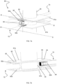
- connection systems 41, 42, 43 comprises a connection flange 91.
- each elongate engagement element is a protrusion 92.
- each protrusion 92 extends in the outward radial direction from said connection flange 91.
- each protrusion 92 has a substantially rectangular cross-section; even more preferably, said substantially rectangular cross-section has radiused angles.
- said radial direction is substantially orthogonal to the longitudinal extension of the rotation shaft 30.
- each protrusion 92 is inserted, at least partly, into the inner cavity 73 at a respective end of a respective blade 70.
- each connection flange 91 is integrally engaged with the rotation shaft 30.
- each connection flange 91 is fitted onto the rotation shaft 30.
- each connection flange 91 comprises at least two protrusions 92.
- each end of a respective blade 70 of the first blade module 50 and/or of the second blade module 60 is coupled to a respective protrusion 92 by means of a glue.
- a glue may be applied onto the protrusions 92 of each connection flange 91.
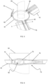
- connection systems 41, 42, 43 comprises a sandwich structure 80.
- each sandwich structure 80 comprises:
- each elongate engagement element is a rectangular shim 84.
- such rectangular shim 84 is inserted into the inner cavity 73 at a respective end of a respective blade 70.
- said end of a respective blade 70 and said rectangular shim 84 are interposed between the pair of coupling shims 82a, 82b and the pair of tightening plates 81a, 81b, as will be described in detail below.
- each tightening plate 81a, 81b is made of steel.
- each coupling shim 82a, 82b has a first surface and a second surface, opposite to said first surface.
- said first surface is substantially flat and said second surface is substantially concave.
- each coupling shim 82a, 82b is made of aluminium.
- the sandwich structure 80 preferably comprises at least two tightening screws 88 and at least two tightening seats 83.
- each tightening screw 88 is inserted into a suitable tightening seat 83 and locked, for example, by means of a respective nut 88'.
- each tightening seat 83 crosses, from top to bottom, the first tightening plate 82a, the first coupling shim 82a, a respective blade 70, the rectangular shim 84, the second coupling shim 82b and the second tightening plate 82b.
- each first tightening plate 82a, each first coupling shim 82a, each rectangular shim 84, each second coupling shim 82b and each second tightening plate 82b of a sandwich structure 80 are equipped with at least two through holes.
- each blade 70 engaged with a sandwich structure 80 has at least two through holes at the end thereof which is to be engaged with said sandwich structure 80. Such holes form the at least two tightening seats 83.
- each tightening seat 83 is parallel to the rotation shaft 30.
- At least two of such tightening seats 83 are arranged at different distances from the rotation shaft 30.
- each coupling shim 82a, 82b faces towards a respective blade 70.
- an electric energy generation system 200 is provided.
- the electric energy generation system 200 comprises:
- Such plurality of hydrodynamic turbines 100a, 100b, 100c, 100d are engaged with the crossbar 201.
- the plurality of hydrodynamic turbines 100a, 100b, 100c, 100d are engaged with the crossbar 201 and are arranged in such a way that the rotation shafts 30a, 30b, 30c, 30b of said hydrodynamic turbines 100a, 100b, 100c, 100d are substantially parallel to one another.
- each rotation shaft 30a, 30b, 30c, 30b is orthogonal to the crossbar 201.
- the rotors 40a, 40b, 40c, 40d are all equal;
- Figure 10 shows different rotors for the sole purpose of illustrating different options.
- a method for generating electric energy is provided.
- the method according to the invention comprises the following steps:
- the electric energy generators 10a, 10b, 10c, 10d of each hydrodynamic turbine 100a, 100b, 100c, 100d are located above the water level W.
- the crossbar 201 is substantially orthogonal to the direction of the water flow.
- the rotors 40a, 40b, 40c, 40d of each hydrodynamic turbine 100a, 100b, 100c, 100d are partially submerged in water.
- Such rotors 40a, 40b, 40c, 40d are made to rotate, by the forces exerted on the respective blades 70 by the water flow, about the longitudinal axis of the respective rotation shaft 30a, 30b, 30c, 30b. By turning they produce, in co-operation with the respective electric energy generator 10a, 10b, 10c, 10d, electric energy.
- the present invention offers important advantages.
- the blades can be created by varying the length of the main tract 71 and/or of each connection tract 71a, 71b by simply changing the bending of the rod made, for example, by extrusion.
- said substantially rectangular inner cavity 73 makes it possible to couple each blade 70 to a rotation shaft 30 by means of:
- connection systems permit reducing the fatigue deterioration of the rotor 40.
Landscapes
- Engineering & Computer Science (AREA)
- Chemical & Material Sciences (AREA)
- Combustion & Propulsion (AREA)
- Mechanical Engineering (AREA)
- General Engineering & Computer Science (AREA)
- Power Engineering (AREA)
- Life Sciences & Earth Sciences (AREA)
- Sustainable Development (AREA)
- Sustainable Energy (AREA)
- Other Liquid Machine Or Engine Such As Wave Power Use (AREA)
- Wind Motors (AREA)
- Engine Equipment That Uses Special Cycles (AREA)
- Turbine Rotor Nozzle Sealing (AREA)
Claims (9)
- Hydrodynamische Turbine (100), umfassend:- einen Elektroenergieerzeuger (10);- einen Rotor (40);- eine Drehwelle (30), wobei die Drehwelle ein erstes Ende und ein zweites Ende aufweist;- das erste Ende der Drehwelle (30) mit dem Rotor (40) in Eingriff steht;- das zweite Ende der Drehwelle (30) mit dem Elektroenergieerzeuger (10) gekoppelt ist;wobei der Rotor (40) umfasst:- ein erstes Verbindungssystem (41) und ein zweites Verbindungssystem (42), wobei jedes Verbindungssystem (41, 42) ganzheitlich mit der Drehwelle (30) in Eingriff steht;- ein erstes Schaufelmodul (50), das mindestens zwei Schaufeln (51a, 51b) umfasst, wobei jede Schaufel (51a, 51b) einen Innenhohlraum (73) umfasst, der einen im Wesentlichen rechteckigen Querschnitt aufweist und mit einem ersten Ende und einem zweiten Ende ausgestattet ist;wobei jedes des ersten und des zweiten Verbindungssystems (41, 42) eine Mehrzahl von länglichen Eingriffselementen (84, 92) mit einem im Wesentlichen rechteckigen Querschnitt umfasst; wobei jedes längliche Eingriffselement (84, 92) mit dem Hohlraum (73) einer jeweiligen Schaufel (51a, 51b) gekoppelt ist;wobei jede Schaufel (51a, 51b) des ersten Schaufelmoduls (50) an einem ersten Ende davon mit dem ersten Verbindungssystem (41) und an einem zweiten Ende davon mit dem zweiten Verbindungssystem (42) gekoppelt ist,wobei mindestens eines des ersten und des zweiten Verbindungssystems (41, 42) eine Sandwichstruktur (80) umfasst; wobei die Sandwichstruktur (80) umfasst:- ein Paar von Klemmplatten (81a, 81b), das auf der Drehwelle (30) angebracht ist;- ein Paar von Kopplungsscheiben (82a, 82b);wobei jedes längliche Eingriffselement eine rechteckige Zwischenscheibe (84) ist;wobei die rechteckige Zwischenscheibe (84) an einem jeweiligen Ende einer jeweiligen Schaufel (70) in den Innenhohlraum (73) eingeführt ist;wobei das Ende einer jeweiligen Schaufel (70) und die rechteckige Zwischenscheibe (84) zwischen das Paar von Kopplungsscheiben (82a, 82b) und das Paar von Klemmplatten (81a, 81b) eingefügt sind.
- Hydrodynamische Turbine (100) nach Anspruch 1, wobei der Rotor (40) umfasst:- ein drittes Verbindungssystem (43), wobei das dritte Verbindungssystem (43) ganzheitlich mit der Drehwelle (30) in Eingriff steht;- ein zweites Schaufelmodul (60), das mindestens zwei Schaufeln (61a, 61b) umfasst, wobei jede Schaufel (61a, 61b) des zweiten Schaufelmoduls (60) einen Innenhohlraum (73) umfasst, der einen im Wesentlichen rechteckigen Querschnitt aufweist und mit einem ersten Ende und einem zweiten Ende ausgestattet ist;wobei das dritte Verbindungssystem (43) eine Mehrzahl von länglichen Eingriffselementen (84, 92) mit einem im Wesentlichen rechteckigen Querschnitt umfasst; wobei jedes längliche Eingriffselement (84, 92) mit dem Hohlraum (73) einer jeweiligen Schaufel (61a, 61b) des zweiten Schaufelmoduls (60) gekoppelt ist;wobei jede Schaufel (61a, 61b) des zweiten Schaufelmoduls (60) an einem ersten Ende davon mit dem zweiten Verbindungssystem (42) und an einem zweiten Ende davon mit dem dritten Verbindungssystem (43) gekoppelt ist.
- Hydrodynamische Turbine (100) nach einem der vorhergehenden Ansprüche, wobei jede Schaufel (70) von mindestens einem des ersten Schaufelmoduls (50) bzw. des zweiten Schaufelmoduls (60) umfasst:- einen ersten Trakt (71) parallel zur Drehwelle;- zwei Verbindungstrakte (71a, 71b), die in ein jeweiliges Verbindungssystem (41, 42, 43) eingreifen;wobei die Verbindungstrakte (71a, 71b) quer, vorzugsweise senkrecht zur Drehwelle (30) angeordnet sind.
- Hydrodynamische Turbine (100) nach einem der vorhergehenden Ansprüche 2 oder 3,wobei das erste Schaufelmodul (50) zwei Schaufeln (51a, 51b) umfasst und das zweite Schaufelmodul (60) zwei Schaufeln (61a, 61b) umfasst;wobei die beiden Schaufeln (51a, 51b) des ersten Schaufelmoduls (50) und die Drehwelle (30) in einer ersten Ebene (X-Z) liegen;wobei die beiden Schaufeln (61a, 61b) des zweiten Schaufelmoduls (60) und die Drehwelle (30) in einer zweiten Ebene (Y-Z) liegen;wobei die erste Ebene (X-Z) und die zweite Ebene (Y-Z) senkrecht zueinander sind.
- Hydrodynamische Turbine (100) nach einem der Ansprüche 2 oder 3,wobei das erste Schaufelmodul (50) eine erste Schaufel (51a) und eine zweite Schaufel (51b) umfasst;das zweite Schaufelmodul (60) eine erste Schaufel (61a) und eine zweite Schaufel (61b) umfasst;wobei die zweite Schaufel (51b) des ersten Schaufelmodus (50), die erste Schaufel (61a) des zweiten Schaufelmoduls (60) und die Drehwelle (30) in einer dritten Ebene (Y'-Z') liegen;wobei die erste Schaufel (51a) des ersten Schaufelmodus (50), die zweite Schaufel (61b) des zweiten Schaufelmoduls (60) und die Drehwelle (30) in einer vierten Ebene (X'-Z') liegen;wobei die dritte Ebene (Y'-Z') und die vierte Ebene (X'-Z') senkrecht zueinander sind.
- Hydrodynamische Turbine (100) nach einem der vorhergehenden Ansprüche, wobei jede Schaufel (70) aus Aluminium hergestellt ist.
- Hydrodynamische Turbine (100) nach einem der vorhergehenden Ansprüche, wobei jede Schaufel (70) ein hydrodynamisches Profil aufweist und einen Kopfabschnitt (78) und einen Endabschnitt (79) umfasst, wobei der Endabschnitt (79) eine Gurney-Klappe (79') umfasst.
- Elektroenergieerzeugungssystem (200), umfassend:- eine Mehrzahl von hydrodynamischen Turbinen (100a, 100b, 100c, 100d) nach einem der vorhergehenden Ansprüche;- eine Querstange (201);wobei die Mehrzahl von hydrodynamischen Turbinen (100a, 100b, 100c, 100d) mit der Querstange (201) in Eingriff steht und so angeordnet ist, dass die Drehwellen (30a, 30b, 30c, 30b) der Mehrzahl von hydrodynamischen Turbinen (100a, 100b, 100c, 100d) im Wesentlichen parallel zueinander sind.
- Verfahren zur Erzeugung von elektrischer Energie, umfassend:- Bereitstellen eines Elektroenergieerzeugungssystems (200) nach dem vorhergehenden Anspruch, wobei die Querstange ein erstes Ende und ein zweites Ende aufweist;- Anbringen des ersten und des zweiten Endes der Querstange auf gegenüberliegenden Seiten eines künstlichen Wasserkanals (202), sodass die Rotoren (40a, 40b, 40c, 40d) jeder hydrodynamischen Turbine (100a, 100b, 100c, 100d) in Wasser getaucht sind.
Applications Claiming Priority (2)
| Application Number | Priority Date | Filing Date | Title |
|---|---|---|---|
| IT102020000009916A IT202000009916A1 (it) | 2020-05-05 | 2020-05-05 | Rotore per turbina idrodinamica |
| PCT/IB2021/053627 WO2021224740A1 (en) | 2020-05-05 | 2021-04-30 | Hydrodynamic turbine rotor |
Publications (3)
| Publication Number | Publication Date |
|---|---|
| EP4146928A1 EP4146928A1 (de) | 2023-03-15 |
| EP4146928B1 true EP4146928B1 (de) | 2024-05-01 |
| EP4146928C0 EP4146928C0 (de) | 2024-05-01 |
Family
ID=71784419
Family Applications (1)
| Application Number | Title | Priority Date | Filing Date |
|---|---|---|---|
| EP21726981.0A Active EP4146928B1 (de) | 2020-05-05 | 2021-04-30 | Hydrodynamischer turbinenrotor |
Country Status (5)
| Country | Link |
|---|---|
| US (1) | US20230184206A1 (de) |
| EP (1) | EP4146928B1 (de) |
| CA (1) | CA3182685A1 (de) |
| IT (1) | IT202000009916A1 (de) |
| WO (1) | WO2021224740A1 (de) |
Cited By (1)
| Publication number | Priority date | Publication date | Assignee | Title |
|---|---|---|---|---|
| WO2026093580A1 (fr) * | 2024-11-04 | 2026-05-07 | Bluetwin | Éolienne |
Families Citing this family (1)
| Publication number | Priority date | Publication date | Assignee | Title |
|---|---|---|---|---|
| US11118564B2 (en) * | 2014-09-30 | 2021-09-14 | Texas Tech University System | Fluid flow energy extraction system and method related thereto |
Family Cites Families (7)
| Publication number | Priority date | Publication date | Assignee | Title |
|---|---|---|---|---|
| KR100962147B1 (ko) * | 2008-06-12 | 2010-06-14 | 원인호 | 풍차용 회전판 |
| KR100933790B1 (ko) * | 2008-07-31 | 2009-12-24 | 주식회사 시그너스파워 | 수직축형 다리우스 풍차 |
| GB2466478A (en) * | 2008-12-02 | 2010-06-30 | Aerovortex Mills Ltd | Suction generation device |
| CN102575637A (zh) * | 2009-07-21 | 2012-07-11 | 生态技术株式会社 | 水力发电装置 |
| WO2011162498A2 (ko) * | 2010-06-21 | 2011-12-29 | Won In Ho | 양기둥 난기류용 풍력발전장치 |
| GB201020743D0 (en) * | 2010-12-07 | 2011-01-19 | Bayram Peter J | A " new" high efficiency, pelton type hydro-electric turbine |
| GB2543988B (en) * | 2014-07-11 | 2020-05-27 | Instream Energy Systems Corp | Hydrokinetic turbine with configurable blades for bi-directional rotation |
-
2020
- 2020-05-05 IT IT102020000009916A patent/IT202000009916A1/it unknown
-
2021
- 2021-04-30 CA CA3182685A patent/CA3182685A1/en active Pending
- 2021-04-30 EP EP21726981.0A patent/EP4146928B1/de active Active
- 2021-04-30 WO PCT/IB2021/053627 patent/WO2021224740A1/en not_active Ceased
- 2021-04-30 US US17/923,615 patent/US20230184206A1/en not_active Abandoned
Cited By (2)
| Publication number | Priority date | Publication date | Assignee | Title |
|---|---|---|---|---|
| WO2026093580A1 (fr) * | 2024-11-04 | 2026-05-07 | Bluetwin | Éolienne |
| FR3168241A1 (fr) * | 2024-11-04 | 2026-05-08 | Bluetwin | Éolienne |
Also Published As
| Publication number | Publication date |
|---|---|
| IT202000009916A1 (it) | 2021-11-05 |
| EP4146928A1 (de) | 2023-03-15 |
| US20230184206A1 (en) | 2023-06-15 |
| CA3182685A1 (en) | 2021-11-11 |
| EP4146928C0 (de) | 2024-05-01 |
| WO2021224740A1 (en) | 2021-11-11 |
Similar Documents
| Publication | Publication Date | Title |
|---|---|---|
| EP2761169B1 (de) | Blatt für windturbine sowie verfahren zur fertigung des blattes | |
| EP2432994B1 (de) | Windturbinenschaufel mit basisteil mit null oder nicht positiver profilwölbung | |
| EP2432991B1 (de) | Windturbinenblatt | |
| EP2432992B1 (de) | Verfahren zur fertigung eines rotorblattes einer windenergieanlage mit einem vorgeformtem segment | |
| US8757982B2 (en) | Wind turbine rotor blade with in-plane sweep and devices using same, and methods for making same | |
| EP3205874B2 (de) | Gezackte hinterkantenplatte für eine windturbinenschaufel | |
| CN102803714B (zh) | 设置有变流装置的风力涡轮机叶片 | |
| EP2432995B1 (de) | Windturbinenblatt mit basisteil mit nicht-idealer eigendrehung | |
| EP2343450B1 (de) | Windturbinenschaufel mit länglich ausgeführter Stromführungsvorrichtung mit einem plattenförmigen Element | |
| EP2253838A1 (de) | Verfahren zum Betrieb einer Windkraftanlage | |
| KR101466419B1 (ko) | 수력 터빈 | |
| EP3707373B1 (de) | Windturbinenrotorblattverbindungen mit schwimmenden verbindern | |
| EP2343451A1 (de) | Windturbinenschaufel mit einer Mehrzahl von Leitvorrichtungen | |
| EP2360374A1 (de) | Windturbinenschaufel mit einer nach vorne gerichteten Leitvorrichtung | |
| JP2011521169A (ja) | 風力タービンまたは水力タービンのロータ用の羽根 | |
| EP2141355A2 (de) | Windturbinenschaufeln mit mehreren Krümmungsraden | |
| CN111094740A (zh) | 未对准翼梁帽的嵌接接头连接 | |
| CA3182685A1 (en) | Hydrodynamic turbine rotor | |
| EP4438888A1 (de) | Windturbinenschaufelwirbelreduktion | |
| EP4680854A1 (de) | Pitchgeregelte windturbine | |
| EP4728178A1 (de) | Windturbinenschaufelanordnung | |
| NZ623566B2 (en) | Blade for wind turbine generator and method for assembling said blade |
Legal Events
| Date | Code | Title | Description |
|---|---|---|---|
| STAA | Information on the status of an ep patent application or granted ep patent |
Free format text: STATUS: UNKNOWN |
|
| STAA | Information on the status of an ep patent application or granted ep patent |
Free format text: STATUS: THE INTERNATIONAL PUBLICATION HAS BEEN MADE |
|
| PUAI | Public reference made under article 153(3) epc to a published international application that has entered the european phase |
Free format text: ORIGINAL CODE: 0009012 |
|
| STAA | Information on the status of an ep patent application or granted ep patent |
Free format text: STATUS: REQUEST FOR EXAMINATION WAS MADE |
|
| 17P | Request for examination filed |
Effective date: 20221104 |
|
| AK | Designated contracting states |
Kind code of ref document: A1 Designated state(s): AL AT BE BG CH CY CZ DE DK EE ES FI FR GB GR HR HU IE IS IT LI LT LU LV MC MK MT NL NO PL PT RO RS SE SI SK SM TR |
|
| DAV | Request for validation of the european patent (deleted) | ||
| DAX | Request for extension of the european patent (deleted) | ||
| GRAP | Despatch of communication of intention to grant a patent |
Free format text: ORIGINAL CODE: EPIDOSNIGR1 |
|
| STAA | Information on the status of an ep patent application or granted ep patent |
Free format text: STATUS: GRANT OF PATENT IS INTENDED |
|
| INTG | Intention to grant announced |
Effective date: 20231207 |
|
| GRAS | Grant fee paid |
Free format text: ORIGINAL CODE: EPIDOSNIGR3 |
|
| GRAA | (expected) grant |
Free format text: ORIGINAL CODE: 0009210 |
|
| STAA | Information on the status of an ep patent application or granted ep patent |
Free format text: STATUS: THE PATENT HAS BEEN GRANTED |
|
| AK | Designated contracting states |
Kind code of ref document: B1 Designated state(s): AL AT BE BG CH CY CZ DE DK EE ES FI FR GB GR HR HU IE IS IT LI LT LU LV MC MK MT NL NO PL PT RO RS SE SI SK SM TR |
|
| REG | Reference to a national code |
Ref country code: GB Ref legal event code: FG4D |
|
| REG | Reference to a national code |
Ref country code: CH Ref legal event code: EP |
|
| REG | Reference to a national code |
Ref country code: DE Ref legal event code: R096 Ref document number: 602021012752 Country of ref document: DE |
|
| REG | Reference to a national code |
Ref country code: IE Ref legal event code: FG4D |
|
| U01 | Request for unitary effect filed |
Effective date: 20240530 |
|
| RAP4 | Party data changed (patent owner data changed or rights of a patent transferred) |
Owner name: HE-POWERGREEN S.R.L. |
|
| U07 | Unitary effect registered |
Designated state(s): AT BE BG DE DK EE FI FR IT LT LU LV MT NL PT SE SI Effective date: 20240610 |
|
| PG25 | Lapsed in a contracting state [announced via postgrant information from national office to epo] |
Ref country code: IS Free format text: LAPSE BECAUSE OF FAILURE TO SUBMIT A TRANSLATION OF THE DESCRIPTION OR TO PAY THE FEE WITHIN THE PRESCRIBED TIME-LIMIT Effective date: 20240901 |
|
| PG25 | Lapsed in a contracting state [announced via postgrant information from national office to epo] |
Ref country code: HR Free format text: LAPSE BECAUSE OF FAILURE TO SUBMIT A TRANSLATION OF THE DESCRIPTION OR TO PAY THE FEE WITHIN THE PRESCRIBED TIME-LIMIT Effective date: 20240501 |
|
| PG25 | Lapsed in a contracting state [announced via postgrant information from national office to epo] |
Ref country code: GR Free format text: LAPSE BECAUSE OF FAILURE TO SUBMIT A TRANSLATION OF THE DESCRIPTION OR TO PAY THE FEE WITHIN THE PRESCRIBED TIME-LIMIT Effective date: 20240802 |
|
| PG25 | Lapsed in a contracting state [announced via postgrant information from national office to epo] |
Ref country code: ES Free format text: LAPSE BECAUSE OF FAILURE TO SUBMIT A TRANSLATION OF THE DESCRIPTION OR TO PAY THE FEE WITHIN THE PRESCRIBED TIME-LIMIT Effective date: 20240501 |
|
| PG25 | Lapsed in a contracting state [announced via postgrant information from national office to epo] |
Ref country code: PL Free format text: LAPSE BECAUSE OF FAILURE TO SUBMIT A TRANSLATION OF THE DESCRIPTION OR TO PAY THE FEE WITHIN THE PRESCRIBED TIME-LIMIT Effective date: 20240501 |
|
| PG25 | Lapsed in a contracting state [announced via postgrant information from national office to epo] |
Ref country code: PL Free format text: LAPSE BECAUSE OF FAILURE TO SUBMIT A TRANSLATION OF THE DESCRIPTION OR TO PAY THE FEE WITHIN THE PRESCRIBED TIME-LIMIT Effective date: 20240501 Ref country code: NO Free format text: LAPSE BECAUSE OF FAILURE TO SUBMIT A TRANSLATION OF THE DESCRIPTION OR TO PAY THE FEE WITHIN THE PRESCRIBED TIME-LIMIT Effective date: 20240801 Ref country code: IS Free format text: LAPSE BECAUSE OF FAILURE TO SUBMIT A TRANSLATION OF THE DESCRIPTION OR TO PAY THE FEE WITHIN THE PRESCRIBED TIME-LIMIT Effective date: 20240901 Ref country code: HR Free format text: LAPSE BECAUSE OF FAILURE TO SUBMIT A TRANSLATION OF THE DESCRIPTION OR TO PAY THE FEE WITHIN THE PRESCRIBED TIME-LIMIT Effective date: 20240501 Ref country code: GR Free format text: LAPSE BECAUSE OF FAILURE TO SUBMIT A TRANSLATION OF THE DESCRIPTION OR TO PAY THE FEE WITHIN THE PRESCRIBED TIME-LIMIT Effective date: 20240802 Ref country code: ES Free format text: LAPSE BECAUSE OF FAILURE TO SUBMIT A TRANSLATION OF THE DESCRIPTION OR TO PAY THE FEE WITHIN THE PRESCRIBED TIME-LIMIT Effective date: 20240501 Ref country code: RS Free format text: LAPSE BECAUSE OF FAILURE TO SUBMIT A TRANSLATION OF THE DESCRIPTION OR TO PAY THE FEE WITHIN THE PRESCRIBED TIME-LIMIT Effective date: 20240801 |
|
| PG25 | Lapsed in a contracting state [announced via postgrant information from national office to epo] |
Ref country code: CZ Free format text: LAPSE BECAUSE OF FAILURE TO SUBMIT A TRANSLATION OF THE DESCRIPTION OR TO PAY THE FEE WITHIN THE PRESCRIBED TIME-LIMIT Effective date: 20240501 |
|
| PG25 | Lapsed in a contracting state [announced via postgrant information from national office to epo] |
Ref country code: SK Free format text: LAPSE BECAUSE OF FAILURE TO SUBMIT A TRANSLATION OF THE DESCRIPTION OR TO PAY THE FEE WITHIN THE PRESCRIBED TIME-LIMIT Effective date: 20240501 Ref country code: RO Free format text: LAPSE BECAUSE OF FAILURE TO SUBMIT A TRANSLATION OF THE DESCRIPTION OR TO PAY THE FEE WITHIN THE PRESCRIBED TIME-LIMIT Effective date: 20240501 |
|
| PG25 | Lapsed in a contracting state [announced via postgrant information from national office to epo] |
Ref country code: SM Free format text: LAPSE BECAUSE OF FAILURE TO SUBMIT A TRANSLATION OF THE DESCRIPTION OR TO PAY THE FEE WITHIN THE PRESCRIBED TIME-LIMIT Effective date: 20240501 |
|
| PG25 | Lapsed in a contracting state [announced via postgrant information from national office to epo] |
Ref country code: SM Free format text: LAPSE BECAUSE OF FAILURE TO SUBMIT A TRANSLATION OF THE DESCRIPTION OR TO PAY THE FEE WITHIN THE PRESCRIBED TIME-LIMIT Effective date: 20240501 Ref country code: SK Free format text: LAPSE BECAUSE OF FAILURE TO SUBMIT A TRANSLATION OF THE DESCRIPTION OR TO PAY THE FEE WITHIN THE PRESCRIBED TIME-LIMIT Effective date: 20240501 Ref country code: RO Free format text: LAPSE BECAUSE OF FAILURE TO SUBMIT A TRANSLATION OF THE DESCRIPTION OR TO PAY THE FEE WITHIN THE PRESCRIBED TIME-LIMIT Effective date: 20240501 Ref country code: CZ Free format text: LAPSE BECAUSE OF FAILURE TO SUBMIT A TRANSLATION OF THE DESCRIPTION OR TO PAY THE FEE WITHIN THE PRESCRIBED TIME-LIMIT Effective date: 20240501 |
|
| REG | Reference to a national code |
Ref country code: DE Ref legal event code: R097 Ref document number: 602021012752 Country of ref document: DE |
|
| PLBE | No opposition filed within time limit |
Free format text: ORIGINAL CODE: 0009261 |
|
| STAA | Information on the status of an ep patent application or granted ep patent |
Free format text: STATUS: NO OPPOSITION FILED WITHIN TIME LIMIT |
|
| 26N | No opposition filed |
Effective date: 20250204 |
|
| U20 | Renewal fee for the european patent with unitary effect paid |
Year of fee payment: 5 Effective date: 20250417 |
|
| REG | Reference to a national code |
Ref country code: CH Ref legal event code: H13 Free format text: ST27 STATUS EVENT CODE: U-0-0-H10-H13 (AS PROVIDED BY THE NATIONAL OFFICE) Effective date: 20251125 |
|
| PG25 | Lapsed in a contracting state [announced via postgrant information from national office to epo] |
Ref country code: MC Free format text: LAPSE BECAUSE OF FAILURE TO SUBMIT A TRANSLATION OF THE DESCRIPTION OR TO PAY THE FEE WITHIN THE PRESCRIBED TIME-LIMIT Effective date: 20240501 |
|
| GBPC | Gb: european patent ceased through non-payment of renewal fee |
Effective date: 20250430 |
|
| PG25 | Lapsed in a contracting state [announced via postgrant information from national office to epo] |
Ref country code: GB Free format text: LAPSE BECAUSE OF NON-PAYMENT OF DUE FEES Effective date: 20250430 |
|
| PG25 | Lapsed in a contracting state [announced via postgrant information from national office to epo] |
Ref country code: CH Free format text: LAPSE BECAUSE OF NON-PAYMENT OF DUE FEES Effective date: 20250430 |
|
| PG25 | Lapsed in a contracting state [announced via postgrant information from national office to epo] |
Ref country code: IE Free format text: LAPSE BECAUSE OF NON-PAYMENT OF DUE FEES Effective date: 20250430 |