EP4146867B1 - Verfahren zur sanierung einer fahrbahn - Google Patents
Verfahren zur sanierung einer fahrbahn Download PDFInfo
- Publication number
- EP4146867B1 EP4146867B1 EP21722903.8A EP21722903A EP4146867B1 EP 4146867 B1 EP4146867 B1 EP 4146867B1 EP 21722903 A EP21722903 A EP 21722903A EP 4146867 B1 EP4146867 B1 EP 4146867B1
- Authority
- EP
- European Patent Office
- Prior art keywords
- clean
- bitumen
- bitumen emulsion
- emulsion
- trackless
- Prior art date
- Legal status (The legal status is an assumption and is not a legal conclusion. Google has not performed a legal analysis and makes no representation as to the accuracy of the status listed.)
- Active
Links
Images


Classifications
-
- E—FIXED CONSTRUCTIONS
- E01—CONSTRUCTION OF ROADS, RAILWAYS, OR BRIDGES
- E01C—CONSTRUCTION OF, OR SURFACES FOR, ROADS, SPORTS GROUNDS, OR THE LIKE; MACHINES OR AUXILIARY TOOLS FOR CONSTRUCTION OR REPAIR
- E01C19/00—Machines, tools or auxiliary devices for preparing or distributing paving materials, for working the placed materials, or for forming, consolidating, or finishing the paving
- E01C19/12—Machines, tools or auxiliary devices for preparing or distributing paving materials, for working the placed materials, or for forming, consolidating, or finishing the paving for distributing granular or liquid materials
- E01C19/21—Machines, tools or auxiliary devices for preparing or distributing paving materials, for working the placed materials, or for forming, consolidating, or finishing the paving for distributing granular or liquid materials for simultaneously but separately applying liquid material and granular or pulverulent material, e.g. bitumen and grit, with or without spreading ; for filling grooves and gritting the filling
-
- C—CHEMISTRY; METALLURGY
- C04—CEMENTS; CONCRETE; ARTIFICIAL STONE; CERAMICS; REFRACTORIES
- C04B—LIME, MAGNESIA; SLAG; CEMENTS; COMPOSITIONS THEREOF, e.g. MORTARS, CONCRETE OR LIKE BUILDING MATERIALS; ARTIFICIAL STONE; CERAMICS; REFRACTORIES; TREATMENT OF NATURAL STONE
- C04B14/00—Use of inorganic materials as fillers, e.g. pigments, for mortars, concrete or artificial stone; Treatment of inorganic materials specially adapted to enhance their filling properties in mortars, concrete or artificial stone
- C04B14/38—Fibrous materials; Whiskers
- C04B14/42—Glass
-
- C—CHEMISTRY; METALLURGY
- C04—CEMENTS; CONCRETE; ARTIFICIAL STONE; CERAMICS; REFRACTORIES
- C04B—LIME, MAGNESIA; SLAG; CEMENTS; COMPOSITIONS THEREOF, e.g. MORTARS, CONCRETE OR LIKE BUILDING MATERIALS; ARTIFICIAL STONE; CERAMICS; REFRACTORIES; TREATMENT OF NATURAL STONE
- C04B26/00—Compositions of mortars, concrete or artificial stone, containing only organic binders, e.g. polymer or resin concrete
- C04B26/02—Macromolecular compounds
- C04B26/26—Bituminous materials, e.g. tar, pitch
-
- E—FIXED CONSTRUCTIONS
- E01—CONSTRUCTION OF ROADS, RAILWAYS, OR BRIDGES
- E01C—CONSTRUCTION OF, OR SURFACES FOR, ROADS, SPORTS GROUNDS, OR THE LIKE; MACHINES OR AUXILIARY TOOLS FOR CONSTRUCTION OR REPAIR
- E01C7/00—Coherent pavings made in situ
- E01C7/08—Coherent pavings made in situ made of road-metal and binders
- E01C7/18—Coherent pavings made in situ made of road-metal and binders of road-metal and bituminous binders
- E01C7/187—Repairing bituminous covers, e.g. regeneration of the covering material in situ, application of a new bituminous topping
-
- C—CHEMISTRY; METALLURGY
- C04—CEMENTS; CONCRETE; ARTIFICIAL STONE; CERAMICS; REFRACTORIES
- C04B—LIME, MAGNESIA; SLAG; CEMENTS; COMPOSITIONS THEREOF, e.g. MORTARS, CONCRETE OR LIKE BUILDING MATERIALS; ARTIFICIAL STONE; CERAMICS; REFRACTORIES; TREATMENT OF NATURAL STONE
- C04B2111/00—Mortars, concrete or artificial stone or mixtures to prepare them, characterised by specific function, property or use
- C04B2111/00474—Uses not provided for elsewhere in C04B2111/00
- C04B2111/0075—Uses not provided for elsewhere in C04B2111/00 for road construction
Definitions
- the present invention generally relates to the field of construction and maintenance of traffic roads and relates more particularly to a process for renovating a traffic road as well as to a spreading machine configured to implement the process.
- the traffic pavements concerned are essentially road traffic pavements but the invention can find applications for any type of ground covering such as for example airstrips, port quays, sports surfaces, car parks, cycle paths.
- Some traffic roads can deteriorate by generating more or less extensive cracks on their surface.
- the causes of these cracks can be multiple, in particular due to the amount of road traffic and/or the structure including the road base.
- These cracks can be oriented perpendicular to the length of the roadway, this can for example be due to the fact that the roadway includes a layer of bituminous coating which has been spread on a structure made up of concrete slabs separated by joints, the cracks occurring at joints.
- the cracks can be oriented in the direction of the length of the roadway, for example this may be due to the fact that the shoulders of the roadway are not stabilized. Cracks can also come from poor adhesion between the layers constituting the roadway.
- cracks can be generated by thermal shrinkage of the materials constituting the roadway.
- EP 1 624 110 it was proposed to apply to the existing cracked roadway a membrane manufactured in-situ and consisting of a layer of a bituminous binder, then a layer of glass fibers cut and sprayed in-situ, then a layer of a bituminous binder, then a spreading of gravel, intended to protect the membrane from the traffic of construction machinery applying the surface coating layer which is then applied on this membrane.
- This spreading of gravel can, however, affect the quality of the bonding of the coated layer to the membrane.
- bonding layers made up of bitumen emulsions are used to ensure bonding between the layers of a road structure in order to ensure its structural integrity and therefore durability.
- the quality of this bonding is essential to the survival of the roadway because it has been sized for the traffic it must receive, like a structure of layers joined together. If these layers slide relative to each other, each of them will be individually subjected to greater deformations and stresses than anticipated and will deteriorate through fatigue quickly, affecting the lifespan of the entire roadway.
- the lifespan of a pavement designed for 20 years can be reduced to 7 or 8 years if its layers are removed.
- Tack coat emulsions are traditionally based on “semi-hard” to “soft” bitumen emulsions; but these have the disadvantage, once broken, of seeing their residual binder adhere to the tires of construction machinery, affecting the entire binder film and therefore the quality of the bonding, but also causing dirt around the site. .
- bitumens By “semi-hard to soft bitumens”, we mean here a bitumen having a penetrability grade at 25°C according to the European standard EN-1426 or the American standard ASTM D5 “Penetration of Bituminous Materials”, greater than or equal to 50 tenths of mm (dmm), and can correspond for example to one or more bitumens having the following classes: 50/70, 70/100, 100/150, 160/200, etc. Furthermore, so-called “clean”/“trackless” bonding bitumen emulsions which, once spread, can be quickly “circulated” by vehicles without the vehicle wheels leaving traces or carrying away the binder. residual, have been developed.
- » characterized by low penetrability, for example having a penetrability grade at 25°C less than or equal to 50 tenths of a mm (dmm), and can correspond for example to one or more bitumens having the following classes: 35/50, 20/30, 10/20, 5/15, etc., and a high “ball-ring” temperature according to the European standard EN-1427 or the American standard ASTM D36 “Softening Point of Bitumen (Ring-and-Ball Apparatus” ). This “hardness” can, however, affect the bonding quality of the residual binder film, especially in cold weather.
- the surface layer is a layer of “clean” (“trackless”) bitumen emulsion or comprising an anhydrous bituminous binder, the “clean” (“trackless”) bitumen emulsion comprising so-called “trackless” bitumen.
- the "clean” (“trackless”) bitumen emulsion giving a residual binder once the breakage of the emulsion has been obtained
- the residual binder of the "clean" (“trackless”) bitumen emulsion having the properties following: a penetrability less than 40 dmm and a Ball-Ring temperature greater than 50°C
- the surface layer (30) is covered with a bituminous coating
- the “clean” bitumen emulsion (“trackless”) contains 30% to 70% bitumen, 30% to 70% water, 0.1% to 10% surfactant(s), stabilizer(s) and /or additive(s), the percentages being by weight
- the anhydrous binder having the following properties after evaporation of the light oils: a penetrability less than 40 dmm and a Ball-Ring temperature greater than 50°C.
- the residual binder of the “clean” (“trackless”) bitumen emulsion preferably has the following properties: a penetrability less than 20 dmm and a Ball-Ring temperature greater than 60°C
- the residual binder of the "clean"("trackless") bitumen emulsion has the following properties: a penetrability of approximately 20 dmm and a Ball-Ring temperature of approximately 60°C
- the anhydrous binder preferably has the following properties after evaporation of the light oils: a penetrability less than 20 dmm and a Ball-Ring temperature greater than 60°C
- the anhydrous binder has the following properties after evaporation of the light oils: a penetrability of approximately 20 dmm and a Ball-Ring temperature of approximately 60°C, - penetrability or penetrability is
- bitumen means a bitumen having a penetrability grade at 25°C according to European standard EN-1426 (2018) ranging from 5 to 40 tenths of a mm (dmm), - hard bitumen can correspond for example to one or more bitumens having the following classes: 35/50, 20/30, 15/25, 10/20, 5/15 according to European standards EN-139
- surfactant(s), stabilizer(s) and/or polymer additive(s), the percentages being by weight, - the bitumen emulsion, whether “clean” or not, has the following properties: Viscosity Saybolt-Furol @ 25C, dry 20-150 Refusal to Sieve % Max. 0.3 Demulsibility % Min.
- emulsion we mean a “heterogeneous system with two or more liquid phases, consisting of a continuous liquid phase and at least a second liquid phase, dispersed in the first in the form of fine droplets” (standard NF EN ISO 862 (NF T73-000) of October 1995); - in the case of bitumen emulsions, the dispersed liquid phase is pure or modified bitumen, possibly fluidized or fluxed; the continuous liquid phase is an aqueous phase generally based on surface agents, such as at least one anionic surfactant, a cationic surfactant and/or a non-ionic surfactant; - by “surfactant” is meant “a chemical compound exhibiting surface activity which, dissolved in a liquid, in particular water, lowers its surface or interfacial tension by preferential adsorption to the liquid/vapor surface or other interfaces » (NF EN ISO 862 standard); - these surfactants are amphiphil
- the adhesiveness dopes can be chosen from alkyl-polyamines such as alkyl amido-polyamines or alkyl imidazo-polyamines; - as a pH modifier, it is possible to use hydrochloric acid; - the residual binder of the “clean” (“trackless”) bitumen emulsion has the following properties: Residue by distillation at 177C [oily distillate, % max] 3 Penetrability dmm, less than 40 Ball-Ring Temperature, °C, greater than 50 Solubility %, Min.
- the residual binder of said emulsion bitumen has the following properties: Elastic covering, % 10C, 210 cm elongation: 55 - 75 Ductility, cm, Min.
- the bonding layer is applied at a dosage of between 0.45 kg/m 2 (0.1 Gal./SY) and 1.8 kg/m 2 (0.4 Gal./SY), - the fibers are glass fibers and the layer of glass fibers is applied at a dosage of between 30 gr/m 2 (0.9 oz./SY) and 120 gr/m 2 (3.5 oz./SY), typically 60 gr/m2 (1.8 oz./SY), - the surface layer is applied at a dosage of between 0.45 kg/m 2 (0.1 Gal./SY) and 1.8 kg/m 2 (0.4 Gal./SY), - the bonding layer is applied at a dosage of 1.125 kg/m2 +/- 0.675 kg/m 2 (0.25 Gal./SY +/- 0.15 Gal./SY) and the surface layer at a dosage of 1.125 kg /m 2 +/- 0.675 kg/m2 (0.25 Gal./SY +/- 0.15 Gal./SY) and in which the fiber
- the step of milling or planing the surface of the roadway is omitted, either by spreading the three layers directly on the surface of the roadway during a renovation, or by a construction or reconstruction of the roadway is carried out and the three layers are spread over a sub-level of the roadway being constructed or reconstructed.
- the three layers can therefore be spread on an existing roadway in the case of a renovation or on a sub-level of a roadway under construction and, in all cases, the surface layer will be the upper layer of the three layers spread , that is to say from bottom to top and superimposed, a first layer called an adhesion layer consisting of a preferably "clean” bitumen emulsion, then a second layer of fibers, then a third layer called a layer of surface made of a “clean” bitumen emulsion (“trackless”).
- bituminous coating is spread over the surface layer in a subsequent step.
- a machine for simultaneously spreading fibers and bitumen emulsion for a method of renovating a vehicle roadway, the machine comprising a reserve of fibers, a reservoir bitumen emulsion and a system for spreading bitumen emulsion and fibers, the system for spreading bitumen emulsion and fibers comprising a first ramp for spreading bitumen emulsion, a fiber projection device and a second ramp for spreading bitumen emulsion, the ramps comprising nozzles, the first ramp, the fiber projection device and the second ramp being arranged in order to spread successively and superimposed during the advancement of the machine and a passage, a first layer called the bonding layer consisting of the bitumen emulsion projected by the first ramp, then a second layer of fibers projected by the fiber projection device, said projected fibers having a maximum length of 12 cm, then a third layer called the surface layer consisting of the bitumen emulsion projected by the second ramp, the bitumen
- the invention finally relates to the roadway obtained by implementing the method of the invention in which the first layer called the bonding layer and the third layer called the surface layer are both composed or constituted of a bitumen emulsion " clean” (“trackless”) and which therefore comprises a sandwich of fibers between two layers of “clean” (“trackless”) bitumen emulsion, the surface layer being further covered with a bituminous coating.
- the first layer called the bonding layer and the third layer called the surface layer are both composed or constituted of a bitumen emulsion " clean” (“trackless”) and which therefore comprises a sandwich of fibers between two layers of “clean” (“trackless”) bitumen emulsion, the surface layer being further covered with a bituminous coating.
- the first layer forming the bonding layer comprises at least or is made up of a bitumen emulsion which is not of the “clean” type (i.e. it is not “trackless” ).
- the first layer forming the bonding layer comprises at least or is made up of an emulsion resulting from the mixture of “soft” and “hard” bitumens.
- the first layer forming the bonding layer is produced by spreading a layer of “soft” bitumen emulsion (ie not “trackless”) followed, on top, by a layer of “hard”/“clean” bitumen emulsion (ie “trackless”).
- the invention it is not necessary to spread an additional layer of gravel on the surface, on the bitumen emulsion covering the fibers, before spreading a bituminous coating. Furthermore, after the application of the surface layer 30, a bituminous coating is almost immediately and directly applied to the surface layer, and, then, compactors can intervene. Interventions on the roadway are therefore reduced and the roadway can be returned to traffic even more quickly compared to traditional methods.
- a process for renovating a vehicle roadway is implemented in which, in a first step, during a single pass of a spreading machine, from bottom to top and superimposed on the roadway, a first layer called a bonding layer comprising at least or consisting of a bitumen emulsion, then a second layer of fibers, then a third layer called surface layer comprising at least or consisting of a "clean"("trackless”) bitumen emulsion, fibers being projected onto the bonding layer and the projected fibers having a maximum length of 12 cm and in a subsequent step, the surface layer is covered with a bituminous coating.
- This “clean” (“trackless”) bitumen emulsion is based on modified or unmodified bitumens, the hardness of which has been adjusted so that they do not adhere to truck tires but can be activated by the temperature of the bituminous coatings at hot applied and thus ensure bonding.
- Added to this thermoadhesive effect is the rapid breakdown of these emulsions, generally in less than 30 minutes, allowing the rapid implementation of the coatings and better site yields.
- a method of renovating a vehicle roadway is implemented in which, in a first step, we spread during a single pass of a spreading machine, from bottom to top and superimposed on the roadway, a first layer called bonding layer comprising at least or consisting of a bitumen emulsion, then a second layer of fibers, then a third layer called surface layer comprising at least or being made up of an anhydrous bituminous binder, fibers being projected onto the bonding layer and the projected fibers having a maximum length of 12 cm and in a subsequent step, the layer is covered with surface of a bituminous coating.
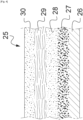
- This renovated roadway 25 was obtained from an initial roadway from which the upper surface was milled or planed (these terms being equivalent in the context of the invention) and the products of milling were eliminated.
- This renovated roadway has been schematized figure 4 by a milled layer 27 of coated type on a sub-base 26. It is understood that the milled layer 27 can be of any type and depends on the structure of the initial roadway. This milled layer 27 can for example be a used road whose surface has been milled.
- a first layer called the bonding layer 28 of "clean"("trackless") bitumen emulsion was spread on the milled layer 27 then a second layer of fibers 29 and, finally a third layer called the surface layer 30 of “clean” bitumen emulsion.
- This assembly is then covered with a bituminous coating (not shown on the figure 4 ) and everything is then compacted. Following the spreading of the three layers 28, 29, 30 and the bituminous coating, a compactor or an equivalent is therefore passed over the whole
- the bonding layer 28 and the surface layer 30 are "clean"("trackless") but one or both are not a bitumen emulsion but an anhydrous bituminous binder spread hot, typically between 110 and 160°C, anhydrous bituminous binders being intrinsically “trackless”.
- the first bonding layer 28 and a second for the surface layer 30 can be based on a softer bitumen in order to promote bonding.
- the surface layer is of the “clean” / “trackless” type.
- a "clean"/"trackless" tack coat is a layer of bitumen emulsion which, once the emulsion has broken down, can be driven on and on which tires or wheels do not leave marks and the bitumen does not stick to tires or wheels.
- thermoadhesive This type of “trackless” emulsion, sometimes referred to as thermoadhesive, is notably formulated with hard bituminous binders, modified or not.
- the residual binder of the “clean” (“trackless”) bitumen emulsion once the breakage of the emulsion has been obtained, generally has the following characteristics: a penetrability of less than 40 dmm and preferably less than 20 dmm, or even d approximately 20 dmm, and a softening point greater than 50°C, preferably greater than 60°C, or even approximately 60°C, according to standards EN-1426 or ASTM D5 “Penetration of Bituminous Materials” and EN- 1427 or ASTM D36 “Softening Point of Bitumen (Ring-and-Ball Apparatus)”.
- residual binder means the residual bitumen obtained once the “clean” (“trackless”) bitumen emulsion has been broken.
- the process of breaking an emulsion takes place in several stages: (1) Flocculation: the globules of the bitumen phase dispersed in the aqueous phase come together, forming a loose network; (2) Coagulation: the bitumen phase and the aqueous phase separate with the agglomeration of the globules into a continuous film; (3) Setting: the bitumen film adheres to its support, the rest of the water is expelled; (4) Ripening: when the residual binder of the emulsion contains light oils which evaporate.
- bituminous emulsion according to the invention may contain the usual additives used in the technique and in particular stabilizers, anti-freeze agents, thickening agents, natural or synthetic latexes (for example a styrene-butadiene-styrene SBS latex, polychloroprene or rubber -butadiene-styrene SBR), which are preferably added to the aqueous dispersing phase.
- stabilizers for example a styrene-butadiene-styrene SBS latex, polychloroprene or rubber -butadiene-styrene SBR
- the anhydrous bituminous binder has similar properties and once spread on a roadway, the latter can be driven on and the tires or wheels do not leave marks and the binder does not stick to the tires or wheels.
- the fibers are typically glass fibers resulting from cutting continuous glass fibers.
- the fibers find themselves embedded in the bitumen emulsion and the bitumen emulsions of the two layers 28, 30 are found in continuity across the layer. of fibers.
- the bonding layer 28 is a bitumen emulsion but which is not of the “clean” type (it is not “trackless”).
- the exemplified spreading machine which is self-propelled, can only store one type of bitumen emulsion and it is a “clean” (“trackless”) bitumen emulsion.
- the machine has in practice a single bitumen emulsion tank of the “clean” type. In variants, it is possible to distribute the “clean” bitumen emulsion between several storage means within the machine, in particular to distribute the masses usefully.
- this machine uses fibers which are glass fibers and these fibers are stored in the machine in the form of continuous fiberglass.
- the machine's bitumen and fiber emulsion spreading system is modular.
- the modules are arranged transversely, side by side, and allow each to spread over a strip of length of the roadway, “clean” bitumen emulsion for the tack layer, fibers for the fiber layer, and the “clean” bitumen emulsion for the surface layer, the layers overlapping.
- Each module comprises, from front to back depending on the direction of travel of the machine: a first nozzle for spreading the "clean” bitumen emulsion for the bonding layer, a tool allowing the traction of continuous fibers, cutting continuous fibers and the projection of the cut fibers towards the roadway on the bonding layer, and a second nozzle for spreading the “clean” bitumen emulsion for the surface layer.
- the first and second nozzles are connected to a common distribution member of the “clean” bitumen emulsion.
- the bitumen emulsion and fiber spreading system therefore has twice as many nozzles as continuous fiber cutting tools due to the fact that each module has two nozzles and one tool.
- This system allows a homogeneous transverse distribution of fibers whose precision is located at any point within a difference of less than 10%, over the width of the treated roadway.
- the tools are placed in a fiber projection device which includes a casing preventing inappropriate dispersion of the cut fibers.
- the casing which is normally closed on its upper and side faces is open towards the bottom and the roadway.
- a first ramp for spreading “clean” bitumen emulsion for the bonding layer is formed for the first nozzles, and for the second nozzles, a second ramp spreading “clean” bitumen emulsion for the surface layer.
- stamp for a set of nozzles but that this term also covers the case where the set of nozzles is supplied by the same collector/feeder and are then controlled globally together in opening and closure, that the case where the nozzles are controlled individually or by sub-assemblies of common sub-collector/feeder.
- Each nozzle produces a fan-shaped jet of “clean” bitumen emulsion substantially over a transverse strip of roadway corresponding substantially to the width of the module and so as to form a substantially homogeneous layer of emulsion under the corresponding ramp by the jets of, first or second respectively, nozzles of the different modules.
- Each tool of the fiber projection device is actuated by a common force transmission member which is a rotating drive shaft arranged transversely and passing through said tools.
- Each tool is removably mounted between a working position where it is driven by the drive shaft and a release position where it is accessible to an operator and stopped.
- the removable tool mounting is pivoting, with the tool emerging from the module upwards.
- the removable mounting of the tool in its module also allows a rest position in which the tool is not driven by the drive shaft while being in the module so that the housing of the fiber projection device is closed on its upper and side faces and allows the machine to work while certain tools have been stopped.
- each tool can be dismantled individually and accessible in a few seconds for cleaning, adjustment, replacement of cutting blades or replacement by standard exchange. . Due to its structure, the risk of accidents during maintenance is reduced since the tools are no longer functional when they are rotated and accessible.
- the tool comprises a first axis which can be rotated on the drive shaft and carrying a cutting roller, a second axis carrying a pressure roller intended to maintain the continuous fiber in contact with the cutting roller and a third axis carrying a holding roller allowing the continuous fiber to be held on the pressure roller upstream of the cutting roller.
- the length of the cut fibers is adjustable. Typically, you can choose at least three sizes of cut fibers: 3, 6 or 12 cm.
- Rotation of the drive shaft is ensured by a hydraulic motor.
- the cut fiber flow rate is adjustable by controlling the rotation speed of the drive shaft.
- the quantity of “clean” bitumen emulsion spread on the roadway is adjustable using an adjustable means of pressurizing the “clean” bitumen emulsion sent to the nozzles.
- the operation of the hydraulic motor is controlled remotely and the first and second ramps include upstream, on the side of the common distribution member, a remotely controlled valve making it possible to cut off or not the spreading of the bitumen emulsion. clean" by the ramps, the control of the activation of the hydraulic motor and the valve being common in order to allow or not the simultaneous spreading of cut fibers and the "clean" bitumen emulsion for the entire spreading system. bitumen and fiber emulsion machine.
- several valves are provided, each controlling a subset of adjacent modules in order to allow or not the spreading for the two nozzles of each module controlled by the valve.
- a valve is provided controlled by module in order to allow or not the spreading for the two nozzles of each module individually.
- the bitumen and fiber emulsion spreading system is mobile vertically at the rear of the machine and can be raised or lowered as needed. During spreading, the system is lowered to be close to the roadway.
- bitumen and fiber emulsion spreading system shown in the figures is a fixed transverse extension unit (i.e. according to the width of the roadway) and whose maximum width (i.e. all modules are functional) of treated roadway is fixed and determined and corresponds substantially to the width of the machine.
- means are provided allowing a maximum width of variable treated roadway exceeding the width of the machine, for example by using several systems for spreading bitumen emulsion and fibers, some of which are foldable on the rear of the machine in the manner folding agricultural spray booms which can be folded at the rear of a tractor to be brought within the width of the tractor.
- at least two systems for spreading bitumen emulsion and fibers are provided, offset longitudinally or in height and capable of translating horizontally between them between a position where the systems are all at the rear of the machine and offset positions. laterally between the systems and the rear of the machine.
- a system for spreading bitumen emulsion and telescopic fibers is provided, the drive shaft being telescopic and the modules being able to move away from each other, the casing comprising telescopic parts or flexible parts with bellows type and the spreading width of the emulsion being regulated by the height of the system relative to the roadway due to the fact that the jets are fan-shaped. Combinations of these different solutions are envisaged to obtain a maximum variable spreading width.
- Said machine shown is therefore a self-propelled road vehicle with a driving and control station.
- the vehicle engine operates a hydraulic pump used to operate the hydraulic motor of the drive shaft.
- the machine shown comprises a bitumen and fiber emulsion spreading system, a “clean” bitumen emulsion reservoir, a means of fluidizing said “clean” bitumen emulsion, a means of pressurizing said emulsion of “clean” bitumen for sending to the ramp nozzles, a reserve of continuous glass fibers, an air compressor and a reserve of compressed air intended at least for the overpressure of the casing and the projection of the cut fibers onto the road.
- Compressed air can also be used to pressurize the “clean” bitumen emulsion and adjusting the air pressure then makes it possible to adjust the spray rate of the emulsion.
- the means of pressurizing the emulsion is an emulsion pump
- a circuit for recirculating the "clean" bitumen emulsion can be provided, the part not sent to the nozzles being discharged into the reservoir of the “clean” bitumen emulsion, the flow rate of this discharged part and/or the flow rate of the emulsion pump being adjustable in order to regulate the quantity of emulsion spread on the roadway.
- the controls and adjustments of the operation of the machine, in particular of the bitumen and fiber emulsion spreading system and associated circuits, are carried out under the supervision of an operator installed in the driving position but a console can be provided. remote control and adjustment, outside the driving position.
- One or more cameras, the display screen(s) of which are in the driving position, can film the bitumen and fiber emulsion spreading system and the roadway behind said system so that the operator has information visual on the system and the result of the spreading.
- the bitumen and fiber emulsion spreading system and machine allow flow adjustments over a wide range for both chopped fiber and emulsion.
- a microprocessor regulation system ensures a substantially constant distribution in quantity of the "clean” bitumen emulsion and cut fibers despite variations in the speed of movement and the number of operational modules and therefore of the spreading width.
- the operator can thus program the quantities of “clean” bitumen emulsion and fibers or a particular fiber/emulsion ratio, and the machine will respect its recommendations independently of the speed and/or will report incompatibilities.
- the invention makes it possible to achieve increased reliability and repeatability, consistency in terms of compliance with objectives and quantities applied, while offering possibilities for adapting significant volume variations.
- the reduced pressure value of the binder for ejection by the nozzles compared to known systems allows a considerable reduction in parasitic emissions and splashes estimated at up to approximately 50%.
- the “clean” bitumen emulsion tank includes stirring means making it possible to homogenize said “clean” bitumen emulsion.
- the means of fluidizing the “clean” bitumen emulsion is heating with a burner of a fuel which is chosen from fuel oil or gas or other and, which is preferably, a light fuel oil.
- the burner is automatically ignited and a temperature regulation system according to a setpoint is implemented. Alternatively, electric heating can be used.
- the hydraulic pump or compressed air can also be used to operate actuators and, for example, one or more lifting cylinders of the bitumen and fiber emulsion spreading system.
- the machine For the storage of glass fibers, the machine has a reserve of continuous fibers in the form of a set of fiber reels.
- the reserve of continuous fibers is arranged at the front of the machine, in an easily accessible location for replacing/reloading the fiber spools and which also promotes a certain distribution of masses on the machine.
- the continuous glass fibers pass from the stockpile to the bitumen emulsion and fiber spreading system through pipes on the upper part of the machine.
- bitumen and fiber emulsion spreading system can be fixed in a removable manner or not at the rear of the machine. We have seen that the bitumen and fiber emulsion spreading system could be raised or lowered and, it is possible, it could also be shifted laterally to overflow laterally on one side or the other of the machine. .
- the vehicle shown has four-wheel drive and allows a spreading speed of between approximately 2 and 5 km/h for a distribution of cut fibers between 0 and approximately 200 grams/m 2 (0 and 5.9 oz/SY) of pavement and a flow rate of “clean” bitumen emulsion between approximately 0 and 3.5 liters/m 2 . (0 and 0.77 Gal. /SY). Values of zero correspond to a cessation of spreading, particularly for travel between sites.
- the four-wheel drive self-propelled road vehicle 2 constituting the machine 1 comprises, at the front, a cabin driving and control 5 for an operator.
- a reserve of fibers comprising reels of continuous fibers, the reserve of fibers being in the form of a hooded box 9 which is at access height so that an operator having opened the hood , can install and replace the spools once they have been unwound.
- the box 9 is mounted at the front with a suspension intended to cushion the effects of road irregularities at the level of the box 9.
- a set of pipes 10 makes it possible to route the continuous fibers towards the rear of the vehicle, in the system 3 for spreading bitumen emulsion and fibers, passing over the upper part of said vehicle.
- the continuous fibers can pass backwards in a different way and, for example, through lateral or even lower conduits.
- Vehicle 2 has a light fuel oil type liquid fuel engine.
- a tank/reservoir 18 of approximately 1000 liters for the “clean” bitumen emulsion occupies the chassis part at the rear of cabin 5.
- the tank has an access hatch in its upper part for filling.
- a heating means is used to fluidize the "clean" bitumen emulsion, in the form of a burner 8, preferably automatic, with light fuel oil which is taken from the fuel tank of the vehicle. Note that in variants not shown, the heating can be with gas, heavy fuel oil or any other combustible substance, or even with electricity.
- a pump 6 for pressurizing the “clean” bitumen emulsion as well as a compressed air tank 7 of approximately 30 liters produced by an air compressor, preferably the vehicle's own air compressor and which is used for braking.
- a portion of the “clean” bitumen emulsion passing through pump 6 can be returned to the bitumen emulsion tank 18 for recirculation.
- the pressurization of the “clean” bitumen emulsion can be obtained with compressed air.
- compressed air can be sent into part of the “clean” bitumen emulsion circuit in order to be able to empty it and clean it at the end of a project, in particular to prevent the nozzles from becoming clogged. .
- the system 3 for spreading bitumen emulsion and fibers is mounted on the rear of the vehicle chassis 2 via a controlled mobile hitch 4.
- the mobile coupling 4 ordered is, on the Figure 1 , raised in the transport position, the system 3 then being moved away from the roadway.
- the mobile hitch 4 can also be placed in a spreading position, the system 3 then being lowered and close to the roadway, as will be seen later in relation to the Figure 2 . It can be envisaged that the mobile hitch 4 also allows lateral movement of the system 3 for spreading bitumen emulsion and fibers.
- Suitable coupling means are implemented between the system 3 for spreading bitumen emulsion and fibers and the vehicle 2 in order to allow the passage of the “clean” bitumen emulsion, compressed air, fibers continuous, energy/hydraulic fluid and monitoring and control circuits.
- the bitumen and fiber emulsion spreading system 3 receives the “clean” bitumen emulsion put under pressure by the pump 6 via at least one flexible pipe not shown here.
- the compressed air from the tank 7 is sent into the system 3 for spreading bitumen emulsion and fibers via flexible pipes.
- the continuous fibers which exit the pipes 10 to reach the system 3 for spreading bitumen emulsion and fibers are intrinsically flexible and can be pulled to be unwound from the reels.
- System 3 for spreading bitumen emulsion and fibers which is seen laterally on the Figure 1 , includes a set of modules. This set of modules forms two ramps with nozzles 14, 15 for spreading “clean” bitumen emulsion and a fiber projection device placed between the two ramps.
- THE fiber projection device which is in a casing, comprises for each module a tool allowing the continuous fibers to be pulled, cut and spread on the roadway.
- the machine 1 consisting of the vehicle 2 and its system 3 for spreading bitumen emulsion and fibers at the rear as well as its reserve of continuous fibers at the front, has the following approximate dimensions: total length 4750mm, width total 1300mm, total height 2300mm, spreading width 1200mm.
- the operating weight of the machine is approximately 4750kg and it can travel between job sites at a maximum speed of approximately 40km/h.
- An automated microcomputer type control system with display screen allows an operator in the vehicle's driving cabin to select operating modes (shutdown of certain modules, respective flow rates of the "clean” bitumen emulsion and/or or cut fibers, speed of advance, etc.), to control and regulate the operation of the machine (flow rates in particular depending on the speed of advance, regulation of the heating of the “clean” bitumen emulsion. .), report anomalies and provide reports of the operational activity of the machine.
- the system 3 for spreading bitumen emulsion and fibers comprises twelve modules, i.e. twelve tools and twenty-four nozzles 14, 15. Such a machine makes it possible to work on a maximum width of 1.20 m, but it also allows you to work at smaller widths in steps of 100 mm (width of a module) by stopping certain modules (stopping the tool and the two corresponding jets).
- the system 3 for spreading bitumen emulsion and fibers because it is modular, is easily adaptable to different widths while retaining similar architecture.
- Controlled valves are implemented in the fluid circuit supplying “clean” bitumen emulsion to the modules in order to be able to cut off the supply of emulsion to each module (two nozzles) individually, on demand.
- all modules are maintained at overpressure with compressed air, even those which are not functional, in order to avoid emulsion vapor rising towards the tools.
- Putting the modules in overpressure can also have a favorable effect on the downward ejection of the cut fibers, the modules being only open downwards in the working position and, preferably, also in the rest position thanks to a double articulation of the tools, and the air flow can only escape from below.
- controlled valves can be provided for the compressed air of each module.
- Means of regulation according to set point of the pressure of the fluid circuit of "clean" bitumen emulsion acting on the pump 6 and/or on the compressed air in the case where the latter is used to pressurize the emulsion can be implemented in order to maintain the pressure in the nozzles 14, 15 substantially constant, the setpoint being able to vary depending on programming and operational conditions (speed of movement, quantity to be spread, etc.).
- Means of regulation according to set point of the pressure of the compressed air can also be implemented.
- the actuator for engaging the tool 13 on the drive shaft 12 and the valve for supplying the “clean” bitumen emulsion to the two nozzles 14, 15 of a module given are controlled in parallel so that when the tool 13 of the module is stopped (or in the release position), the supply of the “clean” bitumen emulsion to the nozzles is also stopped.
- FIG. 2 allows you to see the system 3 for spreading bitumen emulsion and fibers in its spreading position, the control of the hitch 4 having lowered it.
- a first nozzle 14 towards the front and a second nozzle 15 towards the rear, for projecting the "clean" bitumen emulsion onto the roadway surround the fiber projection device with its modules each comprising a tool 13 responsible for distributing cut fibers on the roadway.
- the tools 13 are actuated by functional engagement on the drive shaft 12 common to the different modules and itself actuated by a motor 11 placed in the system 3 for spreading bitumen and fiber emulsion.
- the motor 11 is preferably hydraulic but in certain variants it can be mechanical, pneumatic or electric, or even other.
- the transmission between the motor 11 and the drive shaft 12 is preferably carried out by belt although other means can be used (chain or gears) or even the drive is direct.
- Each of the tools 13 is removably mounted in its module between a release position where it is accessible to an operator outside the module and stopped and two positions where it is located in the module: a working position where it is engaged and driven by the drive shaft and a rest position where it is stopped, the tool is no longer engaged.
- the removable assembly of the tool 13 pivots on a hinge 17, the tool emerging from the module upwards by tilting to allow free access to the operator, towards the rear, to the rollers, cutting means, d drive and others, the latter being on a tilting tool chassis.
- the module When the tool is in the module (in the working or rest position), the module is closed on all its sides except the lower side towards the ground. Thanks to a second articulation within the tool, it is possible to have a working position (functionally engaged on the drive shaft) and a rest position (non-engaged) while the tool is in the module and the closed module.
- each of the tools of the modules comprises a first axis 19 on which is located the part engaging on the drive shaft 12 by friction to transmit the torque/rotational movement to a cutter roller.
- a cutting roller 20 with interchangeable blades is mounted on this first axis 19.
- a rubberized wheel (or other material) is mounted integral with the drive shaft 12 and it is through this wheel that the cutting roller can be engaged.
- the tool further comprises on a second axis, a pressure roller 21 mounted freely in rotation which makes it possible to maintain the continuous fiber in contact with the cutting roller in order to allow its cutting. The pressure of the pressure roller is ensured by an adjustable spring system 23 allowing wear compensation and pressure adjustment.
- a holding roller 22 also mounted freely in rotation on a third axis, allows the continuous fiber to be maintained on the pressure roller 21 upstream of the cutting roller 20 while avoiding the release towards the rear of the continuous fiber when the tool is at rest.
- the position of the retaining roller 22 is adjustable and it is spring-loaded to compensate for wear.
- These elements, axes and rollers, are mounted on a articulated support at 24 which allows, depending on its position, the tool to be placed in the working position or in the rest position.
- This support is itself mounted articulated at 17 relative to the chassis of the module in order to allow the tool to be completely tilted out of the module in a tool release position for cleaning, maintenance or replacement of elements. .
- Bearings are implemented at some of the separations between modules and at both ends of the system 3 for spreading bitumen emulsion and fibers to maintain the drive shaft at the same time.
- the drive shaft 12 may be continuous or not (for example segmented, in particular in two parts meshing/engaging) across the system 3 for spreading bitumen emulsion and fibers. It is understood that the machine can be modified according to needs without departing from the scope defined by the claims. It is also possible to install the system for spreading bitumen emulsion and fibers on a trailer coupled to a vehicle, the whole forming the spreading machine for the renovation of traffic roads allowing the implementation of the method of the invention. In the case where the machine is designed to spread two types of bitumen emulsion including a “clean” one, the machine can include two spreading lines each with a pump and regulation means as well as two tanks or, then, a tank separated into two independent parts.
- One of the two tanks or part of the single tank may contain a soft bitumen emulsion, that is to say an emulsion which is not a “clean”/“trackless” emulsion, the second tank or the other part of the single tank containing the “clean”/“trackless” emulsion.
- a soft bitumen emulsion that is to say an emulsion which is not a “clean”/“trackless” emulsion
- the second tank or the other part of the single tank containing the “clean”/“trackless” emulsion.
- the invention therefore makes it possible to improve the bonding of the coated layer to the “membrane” formed by the bonding layer-fiber-surface layer sandwich, by eliminating the application of protective gravel, thanks to the use of an emulsion for a so-called “clean” (“trackless”) bonding layer.
- the target residual bitumen dosages are approximately between 0.4 kg/m 2 and 0.6 kg/m 2 (0.09 Gal. /SY and 0.14 Gal. /SY) with a fiber dosage of approximately 100 gr/m 2 (3.0 oz/SY)
- the bonding performances obtained by the invention are also improved compared to a "clean" bonding layer alone with a binder dosage equivalent to that of the "membrane” of the invention, the fibers therefore intervening in the bonding performance, which was not expected.
Landscapes
- Engineering & Computer Science (AREA)
- Chemical & Material Sciences (AREA)
- Structural Engineering (AREA)
- Ceramic Engineering (AREA)
- Civil Engineering (AREA)
- Architecture (AREA)
- Materials Engineering (AREA)
- Organic Chemistry (AREA)
- Road Paving Structures (AREA)
- Road Paving Machines (AREA)
Claims (12)
- Verfahren zur Sanierung einer Fahrbahn, bei dem man in einem ersten Schritt bei einem einzigen Durchlauf einer Streumaschine, von unten nach oben und auf der Fahrbahn (26, 27) übereinander, eine als Haftschicht (28) bezeichnete und bitumenhaltige erste Schicht, dann eine zweite Schicht (29) aus Fasern, dann eine als Oberflächenschicht (30) bezeichnete dritte Schicht aufbringt, wobei Fasern auf die Haftschicht geschleudert werden und die geschleuderten Fasern eine maximale Länge von 12 cm haben, dadurch gekennzeichnet, daß die Oberflächenschicht (30) eine "saubere" ("spurenfreie") Bitumenemulsionsschicht ist oder ein wasserfreies bitumenartiges Bindemittel aufweist,wobei die "saubere" ("spurenfreie") Bitumenemulsion einen sogenannten "harten" Bitumen aufweist, wobei die "saubere" ("spurenfreie") Bitumenemulsion nach dem Brechen der erhaltenen Emulsion ein Restbindemittel ergibt, wobei das Restbindemittel der "sauberen' ("spurenfreien") Bitumenemulsion die folgenden Eigenschaften aufweist: eine Durchdringbarkeit von weniger als 40 dmm und eine Ring-Kugel-Erweichungstemperatur von mehr als 50 °C,und daß man die Oberflächenschicht (30) bei einem späteren Schritt mit einem bituminösen Mischgut bedeckt,und daß die "saubere" ("spurenfreie ") Bitumenemulsion 30 % bis 70 % Bitumen, 30 % bis 70 % Wasser, 0,1 % bis 10 % oberflächenaktive(s) Mittel, Stabilisatoren) und/oder Zusatzstoffe) aufweist, wobei die Prozente Gewichtsprozente sind, wobei das wasserfreie Bindemittel nach Verdunsten der leichten Öle die folgenden Eigenschaften aufweist: eine Durchdringbarkeit von weniger als 40 dmm und eine Ring-Kugel-Erweichungstemperatur von mehr als 50 °C.
- Verfahren gemäß Anspruch 1, wobei das Restbindemittel der "sauberen" ("spurenfreien") Bitumenemulsion die folgenden Eigenschaften aufweist: Durchdringbarkeit weniger als 20 dmm und Ring-Kugel-Erweichungstemperatur von mehr als 60 °C.
- Verfahren gemäß Anspruch 1 oder Anspruch 2, wobei die "saubere" ("spurenfreie") Bitumenemulsion 30 % bis 70 % Bitumen, 30 % bis 70 % Wasser, 0,1 % bis 3 % oberflächenaktive(s) Mittel, Stabilisator(en) und/oder Zusatzstoffe) aufweist, wobei die Prozente Gewichtsprozente sind.
- Verfahren gemäß einem der Ansprüche 1 bis 3, wobei der bzw. die Zusatzstoffe ein Polymer ist oder Polymere sind.
- Verfahren gemäß einem der Ansprüche 1 bis 4, wobei die Haftschicht (28) entweder eine "saubere ("spurenfreie") Bitumenemulsion oder ein wasserfreies bitumenartiges Bindemittel aufweist
oder eine andere Bitumenemulsion als eine "saubere" ("spurenfreie") Bitumenemulsion oder ein anderes Bindemittel als ein wasserfreies bitumenartiges Bindemittel aufweist. - Verfahren gemäß einem der Ansprüche 1 bis 5, wobei die Fasern aus Glasfasern und synthetischen Fasern und organischen Fasern ausgewählt sind.
- Verfahren gemäß einem der Ansprüche 1 bis 6, wobei die Bitumenemulsion, sei sie "sauber" oder nicht, die folgenden Eigenschaften aufweist:Seybolt-Furol-Viskosität @ 25C, Sek.: 20 - 150Siebrückhalt % max.: 0,3Entmischung % min.: 40Lagerfestigkeit % max. : 1.
- Verfahren gemäß einem der Ansprüche 1 bis 7, wobei die "saubere" ("spurenfreie") Bitumenemulsion ein Restbindemittel aufweist und das Restbindemittel die folgenden Eigenschaften aufweist:Destillationsrest bei 177C [öliges Destillat, % max.]: 3Lösbarkeit %, min.: 97.
- Verfahren gemäß einem der Ansprüche 1 bis 8, wobei die Haftschicht mit einer Dosierung von 1,125 kg/m2 +/- 0,675 kg/m2 (0,25 Gal./SY +/- 0,15 Gal./SY) und die Oberflächenschicht mit einer Dosierung von 1,125 kg/m2 +/- 0,675 kg/m2 (0,25 Gal./SY +/- 0,15 Gal./SY) aufgebracht wird und wobei die Fasern Glasfasern sind und die Glasfaserschicht mit einer Dosierung von 75 gr/m2 +/- 45 gr/m2 (2,2 Oz./SY +/- 1,3/Oz./SY aufgebracht wird.
- Verfahren gemäß einem der Ansprüche 1 bis 9, wobei man vor dem ersten Schritt die Oberfläche der Fahrbahn abfräst oder abhobelt, um Oberflächenmaterial der Fahrbahn abzulösen, und das abgelöste Material von der Fahrbahn entfernt.
- Verfahren gemäß Anspruch 10, wobei die abgefräste oder abgehobelte Fahrbahn parallele und der Länge der Fahrbahn nach ausgerichtete Rillen aufweist und hinreichend viel Bitumenemulsion und Fasern ausgebreitet werden, um eine im Wesentlichen gleichmäßige Oberfläche zu erhalten.
- Verfahren gemäß einem der Ansprüche 1 bis 11, wobei das wasserfreie bitumenartige Bindemittel heiß aufgetragen wird.
Priority Applications (1)
| Application Number | Priority Date | Filing Date | Title |
|---|---|---|---|
| HRP20240962TT HRP20240962T1 (hr) | 2020-05-05 | 2021-05-04 | Način obnove prometne ceste za vozila |
Applications Claiming Priority (2)
| Application Number | Priority Date | Filing Date | Title |
|---|---|---|---|
| FR2004460A FR3109946B1 (fr) | 2020-05-05 | 2020-05-05 | Procédé de rénovation d’une chaussée de circulation et machine de répandage. |
| PCT/EP2021/061759 WO2021224282A1 (fr) | 2020-05-05 | 2021-05-04 | Procédé de rénovation d'une chaussée de circulation de véhicules et machine de répandage simultané de fibres et d'émulsion de bitume |
Publications (3)
| Publication Number | Publication Date |
|---|---|
| EP4146867A1 EP4146867A1 (de) | 2023-03-15 |
| EP4146867B1 true EP4146867B1 (de) | 2024-06-26 |
| EP4146867C0 EP4146867C0 (de) | 2024-06-26 |
Family
ID=71662088
Family Applications (1)
| Application Number | Title | Priority Date | Filing Date |
|---|---|---|---|
| EP21722903.8A Active EP4146867B1 (de) | 2020-05-05 | 2021-05-04 | Verfahren zur sanierung einer fahrbahn |
Country Status (9)
| Country | Link |
|---|---|
| US (1) | US20230193569A1 (de) |
| EP (1) | EP4146867B1 (de) |
| AU (1) | AU2021267135A1 (de) |
| CA (1) | CA3177808A1 (de) |
| FR (1) | FR3109946B1 (de) |
| HR (1) | HRP20240962T1 (de) |
| HU (1) | HUE067787T2 (de) |
| PL (1) | PL4146867T3 (de) |
| WO (1) | WO2021224282A1 (de) |
Families Citing this family (2)
| Publication number | Priority date | Publication date | Assignee | Title |
|---|---|---|---|---|
| DE102022123625B3 (de) * | 2022-09-15 | 2023-12-14 | Wirtgen Gmbh | Nachbehandlungsmaschine |
| CN115369721B (zh) * | 2022-09-30 | 2023-11-17 | 贵州省遵义公路管理局 | 路面复合封层撒布车 |
Family Cites Families (11)
| Publication number | Priority date | Publication date | Assignee | Title |
|---|---|---|---|---|
| NZ238000A (en) * | 1990-05-10 | 1993-10-26 | Shell Int Research | Vehicle mounted applicator for even distribution of tar binder reinforced with glass fibres |
| FR2661929B1 (fr) * | 1990-05-14 | 1993-02-05 | Screg Routes & Travaux | Dispositif de fabrication d'une couche intermediaire dans une membrane routiere sur le sol. |
| FR2731709B1 (fr) | 1995-03-15 | 1997-06-06 | Colas Sa | Emulsion anionique d'un liant bitumineux, dur dans un etat final, et procede de fabrication d'une telle emulsion |
| US6648547B2 (en) * | 2001-02-28 | 2003-11-18 | Owens Corning Fiberglas Technology, Inc. | Method of reinforcing and waterproofing a paved surface |
| US20040253384A1 (en) * | 2003-06-10 | 2004-12-16 | Simmons C. David | System and method for coating and sealing structural surfaces |
| FR2873722B1 (fr) | 2004-08-02 | 2006-10-13 | Colas Sa | Dispositif modulaire de repandage simultane de fibres coupees et de liants et machine de repandage |
| PL2723818T3 (pl) * | 2011-06-24 | 2016-07-29 | Akzo Nobel Chemicals Int Bv | Dodatki do kompozycji zawierających bitum |
| FR3034778B1 (fr) * | 2015-04-10 | 2017-04-28 | Total Marketing Services | Additif dispersant des asphaltenes et ses utilisations |
| WO2017161369A1 (en) * | 2016-03-18 | 2017-09-21 | Gorman Group Llc | Machine, system and method for resurfacing existing roads |
| US10975530B2 (en) * | 2016-03-18 | 2021-04-13 | The Gorman Group Llc | Machine, system and method for resurfacing existing roads using premixed stress absorbing membrane interlayer (SAMI) material |
| US10851500B2 (en) * | 2019-04-23 | 2020-12-01 | Manhole Adjusting Inc. | Recycled asphalt compositions and methods thereof |
-
2020
- 2020-05-05 FR FR2004460A patent/FR3109946B1/fr active Active
-
2021
- 2021-05-04 AU AU2021267135A patent/AU2021267135A1/en active Pending
- 2021-05-04 HR HRP20240962TT patent/HRP20240962T1/hr unknown
- 2021-05-04 CA CA3177808A patent/CA3177808A1/fr active Pending
- 2021-05-04 EP EP21722903.8A patent/EP4146867B1/de active Active
- 2021-05-04 PL PL21722903.8T patent/PL4146867T3/pl unknown
- 2021-05-04 HU HUE21722903A patent/HUE067787T2/hu unknown
- 2021-05-04 WO PCT/EP2021/061759 patent/WO2021224282A1/fr not_active Ceased
- 2021-05-04 US US17/923,399 patent/US20230193569A1/en active Pending
Also Published As
| Publication number | Publication date |
|---|---|
| FR3109946B1 (fr) | 2022-06-03 |
| US20230193569A1 (en) | 2023-06-22 |
| CA3177808A1 (fr) | 2021-11-11 |
| AU2021267135A1 (en) | 2022-12-08 |
| PL4146867T3 (pl) | 2024-10-28 |
| HUE067787T2 (hu) | 2024-11-28 |
| EP4146867A1 (de) | 2023-03-15 |
| WO2021224282A1 (fr) | 2021-11-11 |
| EP4146867C0 (de) | 2024-06-26 |
| HRP20240962T1 (hr) | 2024-10-25 |
| FR3109946A1 (fr) | 2021-11-12 |
Similar Documents
| Publication | Publication Date | Title |
|---|---|---|
| EP4146867B1 (de) | Verfahren zur sanierung einer fahrbahn | |
| US7585128B2 (en) | Method for adding foaming agents to pavement aggregate | |
| US20140270953A1 (en) | Road strengthening and reinforcement during a recycling process | |
| FR2484493A1 (fr) | Procede et dispositif en vue de reparer des fissures ou des joints longitudinaux dans des revetements routiers | |
| US20060198698A1 (en) | Method for Depositing Pavement Rejuvenation Material into a Layer of Aggregate | |
| CA2783424C (en) | Material management system and method for continuous cold in-place recycling of pavement | |
| NO179110B (no) | Fremgangsmåte og innretning for å danne et dekke på en overflate, f.eks. et veidekke | |
| EP1624110B1 (de) | Modulare Simultan-Streuvorrichtung für Schnittfasern und Bindemittel und Streufahrzeug | |
| EP0736629B1 (de) | Verfahren und Vorrichtung zum Aufbringen einer Haftschicht und eine solche Schicht enthaltender Strassenbelag | |
| EP2960372A1 (de) | Vorrichtung zum verteilen eines bituminösen mischguts, ausgehend von einer asphaltschicht mit definierter stärke und entsprechendes verfahren zur umsetzung | |
| WO2004080151A2 (en) | Pavement recycling machine and method of recycling pavement | |
| US11634875B2 (en) | Pavement repair method and system thereof | |
| EP3455411A1 (de) | Vorrichtung für vor-ort-recycling von materialien eines strassenbelags sowie zerkleinerungsvorrichtung zur zerkleinerung von abfall aus einem strassenbelag | |
| EP3516117B1 (de) | Verfahren zur herstellung einer strassenoberfläche | |
| EP1840267A2 (de) | Vorrichtung und Verfahren zum Einspritzen von Zementschlamm in poröse Straßenbeläge | |
| WO2016020258A1 (en) | Apparatus and process for repairing a longitudinal joint | |
| US7712996B2 (en) | Fogging system for an asphalt recycling machine | |
| FR2661929A1 (fr) | Dispositif de fabrication d'une couche intermediaire dans une membrane routiere sur le sol. | |
| BE1021628B1 (fr) | Rampe d'épandage de lait de chaux et camion-citerne destiné à l'épandage de lait de chaux | |
| FR2759705A1 (fr) | Emulsion aqueuse d'un produit bitumineux | |
| Lawson | Maintenance solutions for bleeding and flushed pavements | |
| US20250304794A1 (en) | Scrub sealer composition, method, and application box | |
| EP0474523A1 (de) | Verfahren zum heissregenerieren an Ort und Stelle einer porösen Fahrbahnschicht | |
| FR2970483A1 (fr) | Remorque reprofileuse automatique - engin tracte par un camion permettant le reprofilage de chaussee et le bouchage des "nids de poules" | |
| Bennett et al. | TECHNICAL REPORT DOCUMENTATION PAGE |
Legal Events
| Date | Code | Title | Description |
|---|---|---|---|
| REG | Reference to a national code |
Ref country code: HR Ref legal event code: TUEP Ref document number: P20240962T Country of ref document: HR |
|
| STAA | Information on the status of an ep patent application or granted ep patent |
Free format text: STATUS: UNKNOWN |
|
| STAA | Information on the status of an ep patent application or granted ep patent |
Free format text: STATUS: THE INTERNATIONAL PUBLICATION HAS BEEN MADE |
|
| PUAI | Public reference made under article 153(3) epc to a published international application that has entered the european phase |
Free format text: ORIGINAL CODE: 0009012 |
|
| STAA | Information on the status of an ep patent application or granted ep patent |
Free format text: STATUS: REQUEST FOR EXAMINATION WAS MADE |
|
| 17P | Request for examination filed |
Effective date: 20221104 |
|
| AK | Designated contracting states |
Kind code of ref document: A1 Designated state(s): AL AT BE BG CH CY CZ DE DK EE ES FI FR GB GR HR HU IE IS IT LI LT LU LV MC MK MT NL NO PL PT RO RS SE SI SK SM TR |
|
| DAX | Request for extension of the european patent (deleted) | ||
| RAV | Requested validation state of the european patent: fee paid |
Extension state: MA Effective date: 20221104 |
|
| STAA | Information on the status of an ep patent application or granted ep patent |
Free format text: STATUS: EXAMINATION IS IN PROGRESS |
|
| 17Q | First examination report despatched |
Effective date: 20230822 |
|
| GRAP | Despatch of communication of intention to grant a patent |
Free format text: ORIGINAL CODE: EPIDOSNIGR1 |
|
| STAA | Information on the status of an ep patent application or granted ep patent |
Free format text: STATUS: GRANT OF PATENT IS INTENDED |
|
| INTG | Intention to grant announced |
Effective date: 20240131 |
|
| GRAS | Grant fee paid |
Free format text: ORIGINAL CODE: EPIDOSNIGR3 |
|
| GRAA | (expected) grant |
Free format text: ORIGINAL CODE: 0009210 |
|
| STAA | Information on the status of an ep patent application or granted ep patent |
Free format text: STATUS: THE PATENT HAS BEEN GRANTED |
|
| AK | Designated contracting states |
Kind code of ref document: B1 Designated state(s): AL AT BE BG CH CY CZ DE DK EE ES FI FR GB GR HR HU IE IS IT LI LT LU LV MC MK MT NL NO PL PT RO RS SE SI SK SM TR |
|
| REG | Reference to a national code |
Ref country code: GB Ref legal event code: FG4D Free format text: NOT ENGLISH |
|
| REG | Reference to a national code |
Ref country code: CH Ref legal event code: EP |
|
| REG | Reference to a national code |
Ref country code: DE Ref legal event code: R096 Ref document number: 602021014837 Country of ref document: DE |
|
| U01 | Request for unitary effect filed |
Effective date: 20240711 |
|
| U07 | Unitary effect registered |
Designated state(s): AT BE BG DE DK EE FI FR IT LT LU LV MT NL PT SE SI Effective date: 20240725 |
|
| REG | Reference to a national code |
Ref country code: SK Ref legal event code: T3 Ref document number: E 44646 Country of ref document: SK |
|
| PG25 | Lapsed in a contracting state [announced via postgrant information from national office to epo] |
Ref country code: GR Free format text: LAPSE BECAUSE OF FAILURE TO SUBMIT A TRANSLATION OF THE DESCRIPTION OR TO PAY THE FEE WITHIN THE PRESCRIBED TIME-LIMIT Effective date: 20240927 |
|
| REG | Reference to a national code |
Ref country code: HR Ref legal event code: T1PR Ref document number: P20240962 Country of ref document: HR |
|
| PG25 | Lapsed in a contracting state [announced via postgrant information from national office to epo] |
Ref country code: NO Free format text: LAPSE BECAUSE OF FAILURE TO SUBMIT A TRANSLATION OF THE DESCRIPTION OR TO PAY THE FEE WITHIN THE PRESCRIBED TIME-LIMIT Effective date: 20240926 Ref country code: GR Free format text: LAPSE BECAUSE OF FAILURE TO SUBMIT A TRANSLATION OF THE DESCRIPTION OR TO PAY THE FEE WITHIN THE PRESCRIBED TIME-LIMIT Effective date: 20240927 Ref country code: RS Free format text: LAPSE BECAUSE OF FAILURE TO SUBMIT A TRANSLATION OF THE DESCRIPTION OR TO PAY THE FEE WITHIN THE PRESCRIBED TIME-LIMIT Effective date: 20240926 |
|
| REG | Reference to a national code |
Ref country code: HU Ref legal event code: AG4A Ref document number: E067787 Country of ref document: HU |
|
| PG25 | Lapsed in a contracting state [announced via postgrant information from national office to epo] |
Ref country code: SM Free format text: LAPSE BECAUSE OF FAILURE TO SUBMIT A TRANSLATION OF THE DESCRIPTION OR TO PAY THE FEE WITHIN THE PRESCRIBED TIME-LIMIT Effective date: 20240626 Ref country code: ES Free format text: LAPSE BECAUSE OF FAILURE TO SUBMIT A TRANSLATION OF THE DESCRIPTION OR TO PAY THE FEE WITHIN THE PRESCRIBED TIME-LIMIT Effective date: 20240626 |
|
| U20 | Renewal fee for the european patent with unitary effect paid |
Year of fee payment: 5 Effective date: 20250303 |
|
| PGFP | Annual fee paid to national office [announced via postgrant information from national office to epo] |
Ref country code: PL Payment date: 20250220 Year of fee payment: 5 |
|
| PLBE | No opposition filed within time limit |
Free format text: ORIGINAL CODE: 0009261 |
|
| STAA | Information on the status of an ep patent application or granted ep patent |
Free format text: STATUS: NO OPPOSITION FILED WITHIN TIME LIMIT |
|
| REG | Reference to a national code |
Ref country code: HR Ref legal event code: ODRP Ref document number: P20240962 Country of ref document: HR Payment date: 20250424 Year of fee payment: 5 |
|
| 26N | No opposition filed |
Effective date: 20250327 |
|
| PGFP | Annual fee paid to national office [announced via postgrant information from national office to epo] |
Ref country code: IS Payment date: 20250512 Year of fee payment: 5 Ref country code: HU Payment date: 20250523 Year of fee payment: 5 |
|
| PGFP | Annual fee paid to national office [announced via postgrant information from national office to epo] |
Ref country code: HR Payment date: 20250424 Year of fee payment: 5 |
|
| PGFP | Annual fee paid to national office [announced via postgrant information from national office to epo] |
Ref country code: CH Payment date: 20250601 Year of fee payment: 5 |
|
| PGFP | Annual fee paid to national office [announced via postgrant information from national office to epo] |
Ref country code: RO Payment date: 20250430 Year of fee payment: 5 |
|
| PGFP | Annual fee paid to national office [announced via postgrant information from national office to epo] |
Ref country code: SK Payment date: 20250428 Year of fee payment: 5 |
|
| PGFP | Annual fee paid to national office [announced via postgrant information from national office to epo] |
Ref country code: CZ Payment date: 20250429 Year of fee payment: 5 |
|
| PG25 | Lapsed in a contracting state [announced via postgrant information from national office to epo] |
Ref country code: MC Free format text: LAPSE BECAUSE OF FAILURE TO SUBMIT A TRANSLATION OF THE DESCRIPTION OR TO PAY THE FEE WITHIN THE PRESCRIBED TIME-LIMIT Effective date: 20240626 |
|
| VS25 | Lapsed in a validation state [announced via postgrant information from nat. office to epo] |
Ref country code: MA Free format text: FAILURE TO ELECT DOMICILE IN THE NATIONAL COUNTRY Effective date: 20240927 |
|
| VS25 | Lapsed in a validation state [announced via postgrant information from nat. office to epo] |
Ref country code: MA Free format text: LAPSE BECAUSE OF FAILURE TO SUBMIT A TRANSLATION OF THE DESCRIPTION OR TO PAY THE FEE WITHIN THE PRESCRIBED TIME-LIMIT Effective date: 20240626 |
|
| U20 | Renewal fee for the european patent with unitary effect paid |
Year of fee payment: 6 Effective date: 20260305 |
|
| PGFP | Annual fee paid to national office [announced via postgrant information from national office to epo] |
Ref country code: GB Payment date: 20260305 Year of fee payment: 6 |
|
| PGFP | Annual fee paid to national office [announced via postgrant information from national office to epo] |
Ref country code: IE Payment date: 20260217 Year of fee payment: 6 |