EP4146599B1 - Filtration device for liquids - Google Patents
Filtration device for liquids Download PDFInfo
- Publication number
- EP4146599B1 EP4146599B1 EP21730800.6A EP21730800A EP4146599B1 EP 4146599 B1 EP4146599 B1 EP 4146599B1 EP 21730800 A EP21730800 A EP 21730800A EP 4146599 B1 EP4146599 B1 EP 4146599B1
- Authority
- EP
- European Patent Office
- Prior art keywords
- container body
- storage area
- filtration device
- filter element
- liquid
- Prior art date
- Legal status (The legal status is an assumption and is not a legal conclusion. Google has not performed a legal analysis and makes no representation as to the accuracy of the status listed.)
- Active
Links
Images

Classifications
-
- C—CHEMISTRY; METALLURGY
- C02—TREATMENT OF WATER, WASTE WATER, SEWAGE, OR SLUDGE
- C02F—TREATMENT OF WATER, WASTE WATER, SEWAGE, OR SLUDGE
- C02F1/00—Treatment of water, waste water, or sewage
- C02F1/001—Processes for the treatment of water whereby the filtration technique is of importance
- C02F1/002—Processes for the treatment of water whereby the filtration technique is of importance using small portable filters for producing potable water, e.g. personal travel or emergency equipment, survival kits, combat gear
-
- B—PERFORMING OPERATIONS; TRANSPORTING
- B01—PHYSICAL OR CHEMICAL PROCESSES OR APPARATUS IN GENERAL
- B01D—SEPARATION
- B01D24/00—Filters comprising loose filtering material, i.e. filtering material without any binder between the individual particles or fibres thereof
- B01D24/02—Filters comprising loose filtering material, i.e. filtering material without any binder between the individual particles or fibres thereof with the filter bed stationary during the filtration
- B01D24/10—Filters comprising loose filtering material, i.e. filtering material without any binder between the individual particles or fibres thereof with the filter bed stationary during the filtration the filtering material being held in a closed container
- B01D24/12—Downward filtration, the filtering material being supported by pervious surfaces
-
- B—PERFORMING OPERATIONS; TRANSPORTING
- B01—PHYSICAL OR CHEMICAL PROCESSES OR APPARATUS IN GENERAL
- B01D—SEPARATION
- B01D24/00—Filters comprising loose filtering material, i.e. filtering material without any binder between the individual particles or fibres thereof
- B01D24/38—Feed or discharge devices
- B01D24/42—Feed or discharge devices for discharging filtrate
-
- B—PERFORMING OPERATIONS; TRANSPORTING
- B01—PHYSICAL OR CHEMICAL PROCESSES OR APPARATUS IN GENERAL
- B01D—SEPARATION
- B01D35/00—Filtering devices having features not specifically covered by groups B01D24/00 - B01D33/00, or for applications not specifically covered by groups B01D24/00 - B01D33/00; Auxiliary devices for filtration; Filter housing constructions
- B01D35/02—Filters adapted for location in special places, e.g. pipe-lines, pumps, stop-cocks
- B01D35/027—Filters adapted for location in special places, e.g. pipe-lines, pumps, stop-cocks rigidly mounted in or on tanks or reservoirs
- B01D35/0273—Filtering elements with a horizontal or inclined rotation or symmetry axis submerged in tanks or reservoirs
-
- B—PERFORMING OPERATIONS; TRANSPORTING
- B01—PHYSICAL OR CHEMICAL PROCESSES OR APPARATUS IN GENERAL
- B01D—SEPARATION
- B01D35/00—Filtering devices having features not specifically covered by groups B01D24/00 - B01D33/00, or for applications not specifically covered by groups B01D24/00 - B01D33/00; Auxiliary devices for filtration; Filter housing constructions
- B01D35/14—Safety devices specially adapted for filtration; Devices for indicating clogging
- B01D35/153—Anti-leakage or anti-return valves
-
- C—CHEMISTRY; METALLURGY
- C02—TREATMENT OF WATER, WASTE WATER, SEWAGE, OR SLUDGE
- C02F—TREATMENT OF WATER, WASTE WATER, SEWAGE, OR SLUDGE
- C02F1/00—Treatment of water, waste water, or sewage
- C02F1/001—Processes for the treatment of water whereby the filtration technique is of importance
- C02F1/003—Processes for the treatment of water whereby the filtration technique is of importance using household-type filters for producing potable water, e.g. pitchers, bottles, faucet mounted devices
-
- C—CHEMISTRY; METALLURGY
- C02—TREATMENT OF WATER, WASTE WATER, SEWAGE, OR SLUDGE
- C02F—TREATMENT OF WATER, WASTE WATER, SEWAGE, OR SLUDGE
- C02F1/00—Treatment of water, waste water, or sewage
- C02F1/28—Treatment of water, waste water, or sewage by sorption
- C02F1/283—Treatment of water, waste water, or sewage by sorption using coal, charred products, or inorganic mixtures containing them
-
- C—CHEMISTRY; METALLURGY
- C02—TREATMENT OF WATER, WASTE WATER, SEWAGE, OR SLUDGE
- C02F—TREATMENT OF WATER, WASTE WATER, SEWAGE, OR SLUDGE
- C02F1/00—Treatment of water, waste water, or sewage
- C02F1/50—Treatment of water, waste water, or sewage by addition or application of a germicide or by oligodynamic treatment
- C02F1/505—Treatment of water, waste water, or sewage by addition or application of a germicide or by oligodynamic treatment by oligodynamic treatment
-
- B—PERFORMING OPERATIONS; TRANSPORTING
- B01—PHYSICAL OR CHEMICAL PROCESSES OR APPARATUS IN GENERAL
- B01D—SEPARATION
- B01D2201/00—Details relating to filtering apparatus
- B01D2201/20—Pressure-related systems for filters
- B01D2201/202—Systems for applying pressure to filters
-
- C—CHEMISTRY; METALLURGY
- C02—TREATMENT OF WATER, WASTE WATER, SEWAGE, OR SLUDGE
- C02F—TREATMENT OF WATER, WASTE WATER, SEWAGE, OR SLUDGE
- C02F2307/00—Location of water treatment or water treatment device
- C02F2307/02—Location of water treatment or water treatment device as part of a bottle
-
- C—CHEMISTRY; METALLURGY
- C02—TREATMENT OF WATER, WASTE WATER, SEWAGE, OR SLUDGE
- C02F—TREATMENT OF WATER, WASTE WATER, SEWAGE, OR SLUDGE
- C02F2307/00—Location of water treatment or water treatment device
- C02F2307/04—Location of water treatment or water treatment device as part of a pitcher or jug
Definitions
- the invention relates to a filtration device according to the pre-amble of claim 1.
- such filtration devices comprise a container body with a storage area for collecting and holding the liquid, e.g. water, until there is a need for extracting a quantity of the liquid from the filtration device.
- the container body comprises an inlet which allows for filling the liquid into the storage area within the container body.
- the inlet can be closed liquid-tight with a lid in order to prevent any unwanted contamination of the liquid inside the storage area from the outside.
- the container body further comprises an outlet which allows for removal of the liquid after the filtration process.
- a suitable filter element is arranged in the flow path between the inlet and the outlet of the container body.
- the filter element is located inside of the storage area and connected to the inlet or outlet of the filtration device.
- Some other filtration devices comprise a filter element that is located outside of the storage area and connected with the storage area by means of a conduit. The filter element may be arranged between the inlet and the storage device or between the storage device and the outlet.
- filter elements are known in prior art, comprising different types of filter media usually disposed in the flow path through the filter element.
- the filter media may comprise activated carbon, zinc or copper, or similar materials that improve e.g. the quality of drinking water.
- the filter element may also comprise membranes or porous materials that remove particles with a particles size that is larger than the pore size of the membrane or porous material that is arranged within the flow path.
- the container body is a bottle with an opening that is used for filling water into the bottle as well as for extracting filtered water from the bottle.
- the opening is usually closed with a cap, whereby a filtering element is mounted at the cap and covers a spout in the cap, through which the filtered water can be extracted from the bottle.
- the cap comprises a spout or an outlet at which a user can suck filtered water from the bottle.
- some bottles comprise an air pump that in many cases is also mounted to the cap.
- an air pump that in many cases is also mounted to the cap.
- a pressure increase inside of the bottle can be generated, resulting in a flow of a corresponding amount of water from the inside of the bottle through the filter element and through the spout or outlet towards outside of the bottle.
- Such filtration devices are disclosed e.g. in US 2013/0048578 A1 or in US 2019/0194032 A1 .
- a cap that contains the inlet and outlet, and that contains or supports the filter element and the air pump is expensive to manufacture and difficult to clean.
- Some other filtration devices comprise a container body that is intended for stationary use.
- the volume of the storage area inside such a container body may be adapted for personal or household use and allow for holding e.g. one or several liters.
- Such a filtration device is disclosed e.g. in WO 2010/091467 A1 .
- a filter element is located at an outlet of a cube-shaped vessel. By applying pressure within the vessel, the liquid stored inside the vessel will be caused to flow through the filter element and pass out of the vessel via the outlet.
- the outlet may be located on top of the vessel, and the filter element can be mounted at the outlet.
- the outlet of the vessel at the bottom, and to provide for an external conduit, namely a riser pipe, that extends upwards and leads to an outlet of the conduit above the top of the vessel.
- the filter element can be a part of this conduit or can be inserted into this conduit, allowing for positioning the filter element outside of the vessel.
- repeated cleaning of the vessel after intervals of use is laborious, as not all areas of the vessel are easily accessible.
- a filtration device with a cylindrical-shaped or oval-shaped storage area that is easily accessible via a large opening at the top of the container body is disclosed in WO 2016/100880 A1 .
- a conduit is an integral part of the filter element and is used or exchanged together with the filter element. It is also described to make use of a conduit that is designed like a riser pipe and attached to the container body. The riser pipe leads from an opening at the bottom of the container body towards a spout located above the fill line of the storage area inside the container body. As with the filtration device discussed above, handling and cleaning of such a filtration device is laborious.
- the objective of the present invention was to provide for a filtration device, which can be easily cleaned without need for manually cleaning angled areas or areas that are difficult to access.
- US 6,733,669 B1 discloses a personal water purification system providing a watertight polymeric container having a removable, threaded inlet fill cap that provides access to an unfiltered upper water receiving chamber. At the lowest integral portion of the receiving chamber, a threaded port is provided for the attachment of a disposable filter cartridge that is vertically threaded into the port. This allows for gravity-induced filtering as opposed to pressure-induced filtering.
- a plurality of filtered water ports are also located in the lower integral portion of the unfiltered water chamber, one or more opposite the other and/or juxtaposed, which allow filtered water to be dispensed through a plurality of channels/conducts from a lower filtered water chamber to a drinking spout provided at a topmost portion of the container, and to flow by gravity when the container is tipped to its side.
- US 2013/0048578 A1 discloses a pressurised water bottle that includes a pressurising tube that delivers air into the bottle to pressurise. Unfiltered water placed in the bottle from a removable top is delivered through a tube that pushes the pressurised water through the bottle and through a filter and out through a spout and to the user to ultimately ingest.
- US 2005/0252844 A1 discloses a water treatment unit positioned adjacent a bottom of a sports water bottle.
- An elongate opening at a top of the water treatment unit is connected to an opening in a cap of the bottle by an elongate conduit such as a straw.
- the bottle is preferably formed of a flexible material, such as plastic, so that when the bottle is squeezed water will be forced from an interior of the bottle surrounding the unit through an inlet, the water treatment unit, the straw and the opening.
- the present invention relates to a filtration device as defined in claim 1.
- all liquid-contacting parts except of the filter element, namely the storage area, the riser pipe and the outlet are manufactured as a one-piece container body, there is no need to dismantle these parts before cleaning. Furthermore, there are no joints where impurities or deposits from the liquid can accumulate and stick, which then have to be cleaned with considerable effort.
- the design and shape of the one-piece container body may be adapted to allow for easy access of all areas inside of the one-piece container body which further facilitates the cleaning of all parts of the filtration device that will be in contact with the liquid during the intended use of the filtration device.
- the inlet of the container body is arranged above the filling level of the storage area and has a cross-sectional area which corresponds to the cross-sectional area of the storage area, so that the storage area is accessible without undercuts via the inlet.
- a large opening of the container body provides for easy access of the inside of the container body.
- the seating for the filter element is only accessible from the storage area.
- the seating for the filter element may be located at the bottom of the storage area.
- the seating is preferably designed and arranged in a manner as to allow for an easy mounting of the filter element in a position that fully covers the output opening of the storage area.
- the flow path of liquid that is extracted from the storage area must traverse the filter element before entering the extraction conduit with the riser pipe.
- the cross-section of the storage area is preferably large enough to allow for a person to mount or dismount the filter element inside the storage area by hand and without the need for tools.
- the seating for the filter element is accessible from outside of the container body via a filter opening in the container body, whereby the filter opening is sealed liquid-tight with a removable filter opening lid, allowing the mounting or removal of the filter element through the filter opening.
- the filter opening is preferably located close by the seating, allowing easy access to the seating from the outside of the container body, which facilitates the mounting and dismounting of the filter element in the seating.
- the filter opening can also be arranged close to the output opening of the storage area and thus close to the input end of the riser pipe, which facilitates access to this end of the riser pipe for cleaning purposes.
- the filter element may have a screw thread so that the filter element can be screwed into the seating. It is also possible to engage the filter element with the seating using a bayonet lock or a snap-in connection. In its position inserted into the seating, the filter element can be sealed against the seating with an additional sealing element.
- the filter element is mounted to the filter opening lid.
- the filter opening lid may also be an integral part of a one-piece housing of the filter media of the filter element.
- the seating of the filter element can be used simultaneously as seating for the filter opening lid. An exchange and replacement of the filter element only requires the dismounting of the filter opening lid from outside of the container body, the removal of the filter element together with the filter opening lid, and subsequent remounting a new filter element until the filter opening lid closes the filter opening in a liquid-tight manner.
- the design of the seating may be adapted for e.g. a bayonet lock or a screw cap.
- the combined filter element and filter opening lid may comprise sealing components like e.g. sealing rings which simultaneously serve to seal the filter opening of the container body as well as the filter element against the seating and thus the flow path of the liquid through the filter element.
- the output end of the riser pipe is connected via a duct to the laterally spaced outlet, whereby the duct is a gutter that is open at the top.
- the riser pipe as well as the duct and the laterally spaced outlet are open at the top, allowing for easy access to all volumes and areas inside of the one-piece container body. If the container body is placed upside down on the top of the container body, any liquid that is previously inside the container body will completely flow out of the container body. Thus, if the container body is cleaned by using a cleaning liquid like, e.g. water with cleaning agents followed by clean water, after placing the container body upside down all remaining water will flow out of the container body and there is no need for manually drying or wiping out the inside of the container body.
- a cleaning liquid like e.g. water with cleaning agents followed by clean water
- the top side of the open duct can optionally be covered by a duct cover that can be fixed on the duct and retained in that position by frictional force or positive locking of the duct cover.
- the duct cover prevents any unwanted contamination by particles or dust of the riser pipe that runs into the duct.
- the duct cover can be made of some elastomeric synthetic material that allows the clipping on of the duct cover on top of the duct.
- the duct cover can be made e.g. of a rigid plastic material or of stainless steel, which allows for a snap-in connection on top of the open duct. It is also possible to combine the duct cover with a lid that covers the inlet of the container body that is next to the duct.
- the duct cover By making the duct cover an integral part of a one-piece top lid that covers simultaneously the inlet of the storage area of the container body as well as the open duct, the number of different parts that must be disassembled for cleaning the filter device and that must be reassembled after a cleaning process can be reduced.
- the duct cover that is removably attachable to the top of the duct combines protection of the filtered liquid against contamination and unwanted exposure to dust etc. with considerable facilitation of cleaning the duct.
- the outlet comprises a downward pointing spout.
- a downward pointing spout facilitates the targeted removal of the filtered liquid.
- an aerator or a swiveling nozzle for example, can be attached to the downward-facing spout to make it as convenient as possible to remove the filtered liquid.
- a further mechanical filter for example a filter membrane, can be detachably attached to the downward pointing spout.
- the container body may optionally be made of a dishwasher suitable material, preferably a dishwasher safe material.
- a dishwasher suitable material preferably a dishwasher safe material.
- the container body can be put into a dishwasher for cleaning the container body.
- the dishwasher can perform a full cleaning of the container body, usually without need for any additional manual cleaning or further manual processing as e.g. drying or wiping of regions inside of the container body that are difficult to access.
- the one-piece container body does not require any disassembling of parts before putting the container body inside a dishwasher.
- no interstices or joints are required for the container body that might allow for unwanted accumulation and retention of contamination, which might require additional manual handling and cleaning procedures.
- the filtration device comprises a base part to accommodate the container body, whereby the pressure generating device is arranged inside of the base part and pressure-transmitting connected to the storage area if the container body is accommodated on the base part.
- the pressure generating device might comprise an electrically operated air pump with a connecting air tube that leads into the storage area inside the container body.
- the air pump, the required electrical parts and the energy supply can be arranged inside the base part.
- the electrical energy can be provided by batteries or via an electrically conductive connection to the household energy supply. It is also possible to provide for a manually operated air pump that can be arranged within the base part. In yet another embodiment, it is also possible to arrange the air pump inside a lid that covers the storage area of the container body. Thus, there is no need for a connecting air tube that connects the air pump with the storage area inside the container body.
- the pressure generating device is separated by a check valve from the storage area inside the container body.
- the check valve can be arranged either inside the container body or as part of the base part or of the connecting air tube.
- the check valve may have a valve ball which is lifted from the valve seat by the overpressure generated by the air pump and releases the air tube as long as the overpressure is maintained.
- figure 1 illustrates a filtration device 1 according to an embodiment of invention.
- the filtration device 1 comprises a container body 2 with a storage area 3 for holding a liquid 4 to be filtered by the filtration device 1.
- the container body 2 comprises an inlet 5 for filling the liquid into the storage area 3 within the container body 2.
- the inlet 5 is a large opening on top of the container body 2, whereby the inlet 5 has a cross-sectional area that corresponds to the cross-sectional area of the storage area 3.
- the storage area 3 is accessible from the top side of the container body 2 via the inlet 5 without any undercuts or edges, which facilitates access to the storage area 3 inside the container body 2.
- a lid 6 can be removably attached over the inlet 5 to the container body 2.
- the lid 6 can be mounted pressure-tight onto the container body 2.
- the lid 6 may comprise a pressure generating device 7 that is only hinted at in figure 1 .
- the pressure generating device 7 can be operated manually or automatically, e.g. by an electric pump. By operating the pressure generating device 7, air is pumped into the storage area 3 via an air tube 8 with a check valve 9.
- a filter element 10 is located in a seating 11 with a thread at a bottom 12 of the storage area 3 inside the container body 2.
- the filter element 10 could also be mounted into the seating 11 by a bayonet lock or by a snap-in connection.
- An extraction conduit 13 connects the storage area 3 via the filter element 10 through a riser pipe 14 with an outlet 15 for discharging the liquid 4 from the storage area 3 inside the container body 2.
- the riser pipe 14 is arranged along an outside wall 16 of the storage area 3 of the container body 2.
- the riser pipe 14 extends from the bottom 12 of the storage area 3 to the outlet 15 close to the top of the container body 2 next to the inlet 5 with the lid 6.
- An input end 17 of the riser pipe 14 is next to the filter element 10.
- An output end 18 of the riser pipe 14 is connected via a horizontal duct 19 with the outlet 15 with a downward pointing spout 20.
- the duct 19 is designed as a gutter that is open at the top.
- the gutter leads to the outlet 15 that is also open at the top.
- a duct cover 21 can be mounted on top of the duct 19 in order to protect the open gutter from any unwanted contamination e.g. by particles or dust that may fall into the gutter.
- the duct cover 21 is made of an elastomeric synthetic material that allows for releasably mounting the duct cover 21 onto the duct 19 by clipping on, plugging on or pushing the duct cover 21 onto the duct 19. It is also possible to make use of a duct cover 21 that is made of a rigid plastic material or of a suitable metal, e.g. a sheet material or stainless steel.
- the storage area 3, the seating 11 for the filter element 10, the extraction conduit 13 comprising the riser pipe 14 and the outlet 15 are integral parts of the one-piece container body 2.
- all components that are in contact with the liquid 4 are manufactured one-piece and without the need for any joints or gaps between individual parts, which must be manufactured separately and then assembled to form the filtration device 1.
- the storage area 3 of the container body 2 can be filled with the liquid 4 to be filtered by the filtration device 1.
- the lid 6 can be mounted pressure-tight on top of the container body 2.
- the pressure generating device 7 is operated, either manually or by means of an electric pump, the pressure inside the storage area 3 rises and a corresponding portion of the liquid 4 is forced through the filter element 10 that is arranged at the bottom 12 of the storage area 3, resulting in performing a filtration process and providing a portion of filtered liquid 4 that is discharged through the extraction conduit and the outlet 15 from the container body 2.
- the filtered liquid 4 rises through the riser pipe 14 and then flows through the horizontally running duct 19 and out of the downward directed outlet spout 20 of the outlet 15.
- the lid 6 can be removed from the container body 2 and the duct cover 21 can be removed from the duct 19.
- the filter element 10 is easily accessible from the inlet 5 and can be manually removed from the seating 11 by performing a rotational movement of the filter element 10, causing the filter element 10 to rotate out of the seating 11.
- the remaining one-piece container body 2 can be easily cleaned e.g. by placing the container body 2 upside down into a dishwasher. All areas inside of the container body 2, including the riser pipe 14 and the duct 19, are easily accessible from the top side of the container body 2.
- FIG. 2 illustrates another embodiment of the container body 2, whereby only a lower region of the container body 2 is shown.
- the filter element 10 is mounted into a seating 11 that is accessible via a filter opening 22 at a bottom 23 of the container body 2.
- the filter opening 22 can be closed liquid-tight with a filter opening lid 24 that can be screwed into a thread 25 on the edge of the filter opening 22.
- the filter element 10 is attached on top of the filter opening lid 24. By mounting the filter opening lid 24 into the filter opening 22, the filter element 10 is located within the seating 11 for the filter element 10 at the bottom 12 of the storage area 3.
- a gap between the filter element 10 and the seating 11 is sealed liquid-tight by an O-ring gasket 26, which is arranged in a circumferential groove around the circular-shaped filter element 10.
- an O-ring gasket 26 is arranged in a circumferential groove around the circular-shaped filter element 10.
- other suitable sealing elements like e.g. an elastomeric sealing lip.
- a flow-through filter medium 27 or, in case of a combined filter element 10, several filter media 27 are arranged between the storage area 3 and the extraction conduit 13, forcing any liquid that is discharged from the storage area 3 through the extraction conduit 13 towards the outlet 15 to flow through the filter medium 27.
- the filter element 10 is easily accessible from outside of the container body 2.
- a spent filter element 10 can be replaced by removing the filter opening lid 24 from the bottom 23 of the container body 2 and by inserting a new filter element 10 together with a corresponding filter opening lid 24 into the filter opening 22 at the bottom 23 of the container body 2.
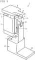
- Figure 3 illustrates another embodiment of the filtration device 1 with the container body 2 that is accommodated onto a base part 28.
- the base part 28 comprises the pressure generating device 7 that is connected via the connecting air tube 8 that leads into the storage area 3 of the container body 2.
- the lid 6 covers the inlet 5 of the storage area 3 of the container body 2 as well as the duct 19 that connects the output end 18 of the riser pipe 14 with the spout 20 that is directed downward towards a platform 29 at a bottom of the base part 28 for placing a glass or a bottle to be filled with the filtered liquid.
Landscapes
- Chemical & Material Sciences (AREA)
- Chemical Kinetics & Catalysis (AREA)
- Life Sciences & Earth Sciences (AREA)
- Hydrology & Water Resources (AREA)
- Engineering & Computer Science (AREA)
- Environmental & Geological Engineering (AREA)
- Water Supply & Treatment (AREA)
- Organic Chemistry (AREA)
- Filtration Of Liquid (AREA)
Description
- The invention relates to a filtration device according to the pre-amble of
claim 1. - For many applications there is a need for a filtration device that enables the filtering of liquids. Even though the filtration device disclosed below is suitable for many different applications, the invention is described using the example of a water filter without limiting the invention to a water filtration device.
- Usually, such filtration devices comprise a container body with a storage area for collecting and holding the liquid, e.g. water, until there is a need for extracting a quantity of the liquid from the filtration device. The container body comprises an inlet which allows for filling the liquid into the storage area within the container body. The inlet can be closed liquid-tight with a lid in order to prevent any unwanted contamination of the liquid inside the storage area from the outside. The container body further comprises an outlet which allows for removal of the liquid after the filtration process.
- A suitable filter element is arranged in the flow path between the inlet and the outlet of the container body. For some filtration devices the filter element is located inside of the storage area and connected to the inlet or outlet of the filtration device. Some other filtration devices comprise a filter element that is located outside of the storage area and connected with the storage area by means of a conduit. The filter element may be arranged between the inlet and the storage device or between the storage device and the outlet.
- Many different filter elements are known in prior art, comprising different types of filter media usually disposed in the flow path through the filter element. The filter media may comprise activated carbon, zinc or copper, or similar materials that improve e.g. the quality of drinking water. The filter element may also comprise membranes or porous materials that remove particles with a particles size that is larger than the pore size of the membrane or porous material that is arranged within the flow path.
- For some filtration devices, the container body is a bottle with an opening that is used for filling water into the bottle as well as for extracting filtered water from the bottle. The opening is usually closed with a cap, whereby a filtering element is mounted at the cap and covers a spout in the cap, through which the filtered water can be extracted from the bottle. Such bottles can easily be carried by a user and used when needed. Sometimes, the cap comprises a spout or an outlet at which a user can suck filtered water from the bottle.
- In order to facilitate the extraction of filtered water from the bottle, some bottles comprise an air pump that in many cases is also mounted to the cap. By manually or automatically operating the air pump a pressure increase inside of the bottle can be generated, resulting in a flow of a corresponding amount of water from the inside of the bottle through the filter element and through the spout or outlet towards outside of the bottle. Such filtration devices are disclosed e.g. in
US 2013/0048578 A1 or inUS 2019/0194032 A1 . However, a cap that contains the inlet and outlet, and that contains or supports the filter element and the air pump is expensive to manufacture and difficult to clean. - Some other filtration devices comprise a container body that is intended for stationary use. The volume of the storage area inside such a container body may be adapted for personal or household use and allow for holding e.g. one or several liters. Such a filtration device is disclosed e.g. in
WO 2010/091467 A1 . A filter element is located at an outlet of a cube-shaped vessel. By applying pressure within the vessel, the liquid stored inside the vessel will be caused to flow through the filter element and pass out of the vessel via the outlet. The outlet may be located on top of the vessel, and the filter element can be mounted at the outlet. It is also possible to located the outlet of the vessel at the bottom, and to provide for an external conduit, namely a riser pipe, that extends upwards and leads to an outlet of the conduit above the top of the vessel. The filter element can be a part of this conduit or can be inserted into this conduit, allowing for positioning the filter element outside of the vessel. However, repeated cleaning of the vessel after intervals of use is laborious, as not all areas of the vessel are easily accessible. - A filtration device with a cylindrical-shaped or oval-shaped storage area that is easily accessible via a large opening at the top of the container body is disclosed in
WO 2016/100880 A1 . For some of the disclosed embodiments, a conduit is an integral part of the filter element and is used or exchanged together with the filter element. It is also described to make use of a conduit that is designed like a riser pipe and attached to the container body. The riser pipe leads from an opening at the bottom of the container body towards a spout located above the fill line of the storage area inside the container body. As with the filtration device discussed above, handling and cleaning of such a filtration device is laborious. - Thus, there is a need for a filtration device which facilitates handling and cleaning. The objective of the present invention was to provide for a filtration device, which can be easily cleaned without need for manually cleaning angled areas or areas that are difficult to access.
-
US 6,733,669 B1 discloses a personal water purification system providing a watertight polymeric container having a removable, threaded inlet fill cap that provides access to an unfiltered upper water receiving chamber. At the lowest integral portion of the receiving chamber, a threaded port is provided for the attachment of a disposable filter cartridge that is vertically threaded into the port. This allows for gravity-induced filtering as opposed to pressure-induced filtering. A plurality of filtered water ports are also located in the lower integral portion of the unfiltered water chamber, one or more opposite the other and/or juxtaposed, which allow filtered water to be dispensed through a plurality of channels/conducts from a lower filtered water chamber to a drinking spout provided at a topmost portion of the container, and to flow by gravity when the container is tipped to its side. -
US 2013/0048578 A1 discloses a pressurised water bottle that includes a pressurising tube that delivers air into the bottle to pressurise. Unfiltered water placed in the bottle from a removable top is delivered through a tube that pushes the pressurised water through the bottle and through a filter and out through a spout and to the user to ultimately ingest. -
US 2005/0252844 A1 discloses a water treatment unit positioned adjacent a bottom of a sports water bottle. An elongate opening at a top of the water treatment unit is connected to an opening in a cap of the bottle by an elongate conduit such as a straw. The bottle is preferably formed of a flexible material, such as plastic, so that when the bottle is squeezed water will be forced from an interior of the bottle surrounding the unit through an inlet, the water treatment unit, the straw and the opening. - The present invention relates to a filtration device as defined in
claim 1. As all liquid-contacting parts except of the filter element, namely the storage area, the riser pipe and the outlet are manufactured as a one-piece container body, there is no need to dismantle these parts before cleaning. Furthermore, there are no joints where impurities or deposits from the liquid can accumulate and stick, which then have to be cleaned with considerable effort. The design and shape of the one-piece container body may be adapted to allow for easy access of all areas inside of the one-piece container body which further facilitates the cleaning of all parts of the filtration device that will be in contact with the liquid during the intended use of the filtration device. According to an advantageous aspect of the invention, the inlet of the container body is arranged above the filling level of the storage area and has a cross-sectional area which corresponds to the cross-sectional area of the storage area, so that the storage area is accessible without undercuts via the inlet. A large opening of the container body provides for easy access of the inside of the container body. - In accordance with an embodiment of the invention, the seating for the filter element is only accessible from the storage area. The seating for the filter element may be located at the bottom of the storage area. The seating is preferably designed and arranged in a manner as to allow for an easy mounting of the filter element in a position that fully covers the output opening of the storage area. Thus, the flow path of liquid that is extracted from the storage area must traverse the filter element before entering the extraction conduit with the riser pipe. The cross-section of the storage area is preferably large enough to allow for a person to mount or dismount the filter element inside the storage area by hand and without the need for tools.
- In yet an alternative embodiment that is also considered advantageous, the seating for the filter element is accessible from outside of the container body via a filter opening in the container body, whereby the filter opening is sealed liquid-tight with a removable filter opening lid, allowing the mounting or removal of the filter element through the filter opening. The filter opening is preferably located close by the seating, allowing easy access to the seating from the outside of the container body, which facilitates the mounting and dismounting of the filter element in the seating. The filter opening can also be arranged close to the output opening of the storage area and thus close to the input end of the riser pipe, which facilitates access to this end of the riser pipe for cleaning purposes.
- The filter element may have a screw thread so that the filter element can be screwed into the seating. It is also possible to engage the filter element with the seating using a bayonet lock or a snap-in connection. In its position inserted into the seating, the filter element can be sealed against the seating with an additional sealing element.
- In order to reduce the handling effort required to replace a used-up filter element, it is optionally possible that the filter element is mounted to the filter opening lid. The filter opening lid may also be an integral part of a one-piece housing of the filter media of the filter element. The seating of the filter element can be used simultaneously as seating for the filter opening lid. An exchange and replacement of the filter element only requires the dismounting of the filter opening lid from outside of the container body, the removal of the filter element together with the filter opening lid, and subsequent remounting a new filter element until the filter opening lid closes the filter opening in a liquid-tight manner. The design of the seating may be adapted for e.g. a bayonet lock or a screw cap. The combined filter element and filter opening lid may comprise sealing components like e.g. sealing rings which simultaneously serve to seal the filter opening of the container body as well as the filter element against the seating and thus the flow path of the liquid through the filter element.
- In accordance with a particularly advantageous embodiment of the invention, the output end of the riser pipe is connected via a duct to the laterally spaced outlet, whereby the duct is a gutter that is open at the top. Thus, the riser pipe as well as the duct and the laterally spaced outlet are open at the top, allowing for easy access to all volumes and areas inside of the one-piece container body. If the container body is placed upside down on the top of the container body, any liquid that is previously inside the container body will completely flow out of the container body. Thus, if the container body is cleaned by using a cleaning liquid like, e.g. water with cleaning agents followed by clean water, after placing the container body upside down all remaining water will flow out of the container body and there is no need for manually drying or wiping out the inside of the container body.
- The top side of the open duct can optionally be covered by a duct cover that can be fixed on the duct and retained in that position by frictional force or positive locking of the duct cover. The duct cover prevents any unwanted contamination by particles or dust of the riser pipe that runs into the duct. The duct cover can be made of some elastomeric synthetic material that allows the clipping on of the duct cover on top of the duct. Alternatively, the duct cover can be made e.g. of a rigid plastic material or of stainless steel, which allows for a snap-in connection on top of the open duct. It is also possible to combine the duct cover with a lid that covers the inlet of the container body that is next to the duct. By making the duct cover an integral part of a one-piece top lid that covers simultaneously the inlet of the storage area of the container body as well as the open duct, the number of different parts that must be disassembled for cleaning the filter device and that must be reassembled after a cleaning process can be reduced. The duct cover that is removably attachable to the top of the duct combines protection of the filtered liquid against contamination and unwanted exposure to dust etc. with considerable facilitation of cleaning the duct.
- According to another aspect of the invention the outlet comprises a downward pointing spout. A downward pointing spout facilitates the targeted removal of the filtered liquid. In addition, an aerator or a swiveling nozzle, for example, can be attached to the downward-facing spout to make it as convenient as possible to remove the filtered liquid. It is also possible that a further mechanical filter, for example a filter membrane, can be detachably attached to the downward pointing spout.
- In order to further facilitate the cleaning of the filtration device, the container body may optionally be made of a dishwasher suitable material, preferably a dishwasher safe material. Thus, the container body can be put into a dishwasher for cleaning the container body. By placing the container body upside down without any lids and duct cover inside a dishwasher, the dishwasher can perform a full cleaning of the container body, usually without need for any additional manual cleaning or further manual processing as e.g. drying or wiping of regions inside of the container body that are difficult to access. Furthermore, the one-piece container body does not require any disassembling of parts before putting the container body inside a dishwasher. In addition, no interstices or joints are required for the container body that might allow for unwanted accumulation and retention of contamination, which might require additional manual handling and cleaning procedures.
- According to an advantageous aspect of the invention the filtration device comprises a base part to accommodate the container body, whereby the pressure generating device is arranged inside of the base part and pressure-transmitting connected to the storage area if the container body is accommodated on the base part. The pressure generating device might comprise an electrically operated air pump with a connecting air tube that leads into the storage area inside the container body. The air pump, the required electrical parts and the energy supply can be arranged inside the base part. The electrical energy can be provided by batteries or via an electrically conductive connection to the household energy supply. It is also possible to provide for a manually operated air pump that can be arranged within the base part. In yet another embodiment, it is also possible to arrange the air pump inside a lid that covers the storage area of the container body. Thus, there is no need for a connecting air tube that connects the air pump with the storage area inside the container body.
- In case that the filtration device comprises such a connecting air tube, it may be advantageous that the pressure generating device is separated by a check valve from the storage area inside the container body. The check valve can be arranged either inside the container body or as part of the base part or of the connecting air tube. The check valve may have a valve ball which is lifted from the valve seat by the overpressure generated by the air pump and releases the air tube as long as the overpressure is maintained.
- The present invention will be more fully understood, and further features will become apparent, when reference is made to the following detailed description and the accompanying drawings. The drawings are merely representative and are not intended to limit the scope of the claims. In fact, those of ordinary skill in the art may appreciate upon reading the following specification and viewing the present drawings that various modifications and variations can be made thereto without deviating from the innovative concepts of the invention. Like parts depicted in the drawings are referred to by the same reference numerals.
-
Figure 1 illustrates a cross-sectional view of a first embodiment of a filtration device with a one-piece container body and a filter element that is accessible from inside the container body, -
Figure 2 illustrates a cross-sectional view of a lower part of another embodiment of the filtration device with the filter element that is accessible from outside the container body, and -
Figure 3 illustrates an exploded perspective view of yet another embodiment of the filtration device with the container body accommodated on top of a base part. - By way of example,
figure 1 illustrates afiltration device 1 according to an embodiment of invention. Thefiltration device 1 comprises acontainer body 2 with astorage area 3 for holding aliquid 4 to be filtered by thefiltration device 1. Thecontainer body 2 comprises aninlet 5 for filling the liquid into thestorage area 3 within thecontainer body 2. Theinlet 5 is a large opening on top of thecontainer body 2, whereby theinlet 5 has a cross-sectional area that corresponds to the cross-sectional area of thestorage area 3. Thus, thestorage area 3 is accessible from the top side of thecontainer body 2 via theinlet 5 without any undercuts or edges, which facilitates access to thestorage area 3 inside thecontainer body 2. - A
lid 6 can be removably attached over theinlet 5 to thecontainer body 2. Thelid 6 can be mounted pressure-tight onto thecontainer body 2. Thelid 6 may comprise apressure generating device 7 that is only hinted at infigure 1 . Thepressure generating device 7 can be operated manually or automatically, e.g. by an electric pump. By operating thepressure generating device 7, air is pumped into thestorage area 3 via anair tube 8 with acheck valve 9. - A
filter element 10 is located in aseating 11 with a thread at a bottom 12 of thestorage area 3 inside thecontainer body 2. Thefilter element 10 could also be mounted into theseating 11 by a bayonet lock or by a snap-in connection. Anextraction conduit 13 connects thestorage area 3 via thefilter element 10 through ariser pipe 14 with anoutlet 15 for discharging the liquid 4 from thestorage area 3 inside thecontainer body 2. Theriser pipe 14 is arranged along anoutside wall 16 of thestorage area 3 of thecontainer body 2. Theriser pipe 14 extends from the bottom 12 of thestorage area 3 to theoutlet 15 close to the top of thecontainer body 2 next to theinlet 5 with thelid 6. An input end 17 of theriser pipe 14 is next to thefilter element 10. Anoutput end 18 of theriser pipe 14 is connected via ahorizontal duct 19 with theoutlet 15 with adownward pointing spout 20. - The
duct 19 is designed as a gutter that is open at the top. The gutter leads to theoutlet 15 that is also open at the top. Aduct cover 21 can be mounted on top of theduct 19 in order to protect the open gutter from any unwanted contamination e.g. by particles or dust that may fall into the gutter. Theduct cover 21 is made of an elastomeric synthetic material that allows for releasably mounting theduct cover 21 onto theduct 19 by clipping on, plugging on or pushing theduct cover 21 onto theduct 19. It is also possible to make use of aduct cover 21 that is made of a rigid plastic material or of a suitable metal, e.g. a sheet material or stainless steel. - The
storage area 3, theseating 11 for thefilter element 10, theextraction conduit 13 comprising theriser pipe 14 and theoutlet 15 are integral parts of the one-piece container body 2. Thus, with the exception of thereplaceable filter element 10, all components that are in contact with theliquid 4 are manufactured one-piece and without the need for any joints or gaps between individual parts, which must be manufactured separately and then assembled to form thefiltration device 1. - After removal of the
lid 6, thestorage area 3 of thecontainer body 2 can be filled with the liquid 4 to be filtered by thefiltration device 1. After filling thestorage area 3 with theliquid 4, thelid 6 can be mounted pressure-tight on top of thecontainer body 2. Afterwards, if thepressure generating device 7 is operated, either manually or by means of an electric pump, the pressure inside thestorage area 3 rises and a corresponding portion of theliquid 4 is forced through thefilter element 10 that is arranged at the bottom 12 of thestorage area 3, resulting in performing a filtration process and providing a portion of filtered liquid 4 that is discharged through the extraction conduit and theoutlet 15 from thecontainer body 2. By operating thepressure generating device 7, the filteredliquid 4 rises through theriser pipe 14 and then flows through the horizontally runningduct 19 and out of the downward directedoutlet spout 20 of theoutlet 15. - In order to perform a cleaning of the
filtration device 1, thelid 6 can be removed from thecontainer body 2 and theduct cover 21 can be removed from theduct 19. Afterwards, thefilter element 10 is easily accessible from theinlet 5 and can be manually removed from theseating 11 by performing a rotational movement of thefilter element 10, causing thefilter element 10 to rotate out of theseating 11. After removing thefilter element 10 from the bottom 12 of thestorage area 3, the remaining one-piece container body 2 can be easily cleaned e.g. by placing thecontainer body 2 upside down into a dishwasher. All areas inside of thecontainer body 2, including theriser pipe 14 and theduct 19, are easily accessible from the top side of thecontainer body 2. -
Figure 2 illustrates another embodiment of thecontainer body 2, whereby only a lower region of thecontainer body 2 is shown. Thefilter element 10 is mounted into aseating 11 that is accessible via afilter opening 22 at a bottom 23 of thecontainer body 2. Before filling theliquid 4 into thestorage area 3, the filter opening 22 can be closed liquid-tight with afilter opening lid 24 that can be screwed into athread 25 on the edge of thefilter opening 22. Thefilter element 10 is attached on top of thefilter opening lid 24. By mounting thefilter opening lid 24 into thefilter opening 22, thefilter element 10 is located within theseating 11 for thefilter element 10 at the bottom 12 of thestorage area 3. A gap between thefilter element 10 and theseating 11 is sealed liquid-tight by an O-ring gasket 26, which is arranged in a circumferential groove around the circular-shapedfilter element 10. Instead of arranging a O-ring gasket 26 within the gap, it is also possible to make use of other suitable sealing elements like e.g. an elastomeric sealing lip. A flow-through filter medium 27 or, in case of a combinedfilter element 10, several filter media 27 are arranged between thestorage area 3 and theextraction conduit 13, forcing any liquid that is discharged from thestorage area 3 through theextraction conduit 13 towards theoutlet 15 to flow through the filter medium 27. - Thus, the
filter element 10 is easily accessible from outside of thecontainer body 2. A spentfilter element 10 can be replaced by removing thefilter opening lid 24 from the bottom 23 of thecontainer body 2 and by inserting anew filter element 10 together with a correspondingfilter opening lid 24 into the filter opening 22 at the bottom 23 of thecontainer body 2. -
Figure 3 illustrates another embodiment of thefiltration device 1 with thecontainer body 2 that is accommodated onto abase part 28. Thebase part 28 comprises thepressure generating device 7 that is connected via the connectingair tube 8 that leads into thestorage area 3 of thecontainer body 2. Thelid 6 covers theinlet 5 of thestorage area 3 of thecontainer body 2 as well as theduct 19 that connects theoutput end 18 of theriser pipe 14 with thespout 20 that is directed downward towards aplatform 29 at a bottom of thebase part 28 for placing a glass or a bottle to be filled with the filtered liquid.
Claims (13)
- A filtration device (1) for liquids, comprising a container body (2) with a storage area (3) for holding the liquid (4) to be filtered by the filtration device (1), whereby the container body (2) comprises an inlet (5) for filling the liquid (4) into the storage area (3) within the container body (2) and with an outlet (15) that is connected to the storage area (3) via an extraction conduit (13) for extracting the liquid (4) from the storage area (3) through the extraction conduit (13) and out of the outlet (15), whereby the extraction conduit (13) comprises a riser pipe (14) with an output end (18) located above a maximum filling level of the liquid (4) within the storage area (3) and connected to the outlet (15), whereby the filtration device (1) further comprises a filter element (10) that is arranged inside the container body (2) such that the liquid (4) that is extracted from the container body (2) must pass the filter element (10) before flowing out of the outlet (15),wherein the container body (2) comprises a seating (11) for removably mounting the filter element (10) to the container body (2), andwherein the storage area (3), the riser pipe (14) and the outlet (15) are integral parts of the one-piece container body (2), characterised in thatan input end (17) of the riser pipe (14) is connected to an output opening of the storage area (3) located at a bottom part of the container body (2), and in thatthe filtration device further comprises a pressure generating device (7) for generating pressure within the container body (2) causing the liquid (4) to pass out of the container body (2) by flowing from the storage area (3) through the extraction conduit (13) and out of the outlet (15).
- The filtration device (1) according to claim 1, characterized in that the inlet (5) of the container body (2) is arranged above the filling level of the storage area (3) and has a cross-sectional area which corresponds to the cross-sectional area of the storage area (3), so that the storage area (3) is accessible without undercuts via the inlet.
- The filtration device (1) according to claim 1 or claim 2, characterized in that the seating (11) for the filter element (10) is only accessible from the storage area (3).
- The filtration device according to claim 3,
wherein the seating (11) for the filter element (10) is located at a bottom of the storage area (3). - The filtration device according to claim 3 or 4,wherein the seating (11) for the filter element (10) is designed and arranged in a manner as to allow for mounting of the filter element (10) in a position that fully covers the output opening of the storage area (3), so thatthe flow path of liquid that is extracted from the storage area (3) must traverse the filter element (10) before entering the extraction conduit (13) within the riser pipe (14).
- The filtration device (1) according to claim 1 or claim 2, characterized in that the seating (11) for the filter element (10) is accessible from outside of the container body (2) via a filter opening (22) in the container body (2), whereby the filter opening (22) is sealed liquid-tight with a removable filter opening lid (24), allowing the mounting or removal of the filter element (10) through the filter opening (22).
- The filtration device (1) according to claim 6, characterized in that the filter element (10) is mounted to the filter opening lid (24).
- The filtration device according to claim 5 or 6,
wherein the filter opening (22) is located close to the output opening of the storage area (3) and thus close to the input end (17) of the riser pipe (14). - The filtration device (1) according to one of the preceding claims, characterized in that the output end (18) of the riser pipe (14) is connected via a duct (19) to the laterally spaced outlet (15), whereby the duct (19) is a gutter open at the top.
- The filtration device (1) according to claim 9, characterized in that the outlet (15) comprises a downward pointing spout (20).
- The filtration device (1) according to one of the preceding claims, characterized in that the container body (2) is made of a dishwasher suitable material.
- The filtration device (1) according to one of the preceding claims, characterized in that the filtration device (1) comprises a base part (28) to accommodate the container body (2), whereby the pressure generating device (7) is arranged inside of the base part (28) and pressure-transmitting connected to the storage area (3) if the container body (2) is accommodated on the base part (28).
- The filtration device (1) according to claim 12, characterized in that the pressure generating device (7) is separated by a check valve (9) from the storage area (3) inside the container body (2).
Applications Claiming Priority (2)
| Application Number | Priority Date | Filing Date | Title |
|---|---|---|---|
| EP20173754.1A EP3907189A1 (en) | 2020-05-08 | 2020-05-08 | Filtration device for liquids |
| PCT/EP2021/000062 WO2021223904A1 (en) | 2020-05-08 | 2021-05-06 | Filtration device for liquids |
Publications (3)
| Publication Number | Publication Date |
|---|---|
| EP4146599A1 EP4146599A1 (en) | 2023-03-15 |
| EP4146599B1 true EP4146599B1 (en) | 2024-10-16 |
| EP4146599C0 EP4146599C0 (en) | 2024-10-16 |
Family
ID=70680315
Family Applications (2)
| Application Number | Title | Priority Date | Filing Date |
|---|---|---|---|
| EP20173754.1A Withdrawn EP3907189A1 (en) | 2020-05-08 | 2020-05-08 | Filtration device for liquids |
| EP21730800.6A Active EP4146599B1 (en) | 2020-05-08 | 2021-05-06 | Filtration device for liquids |
Family Applications Before (1)
| Application Number | Title | Priority Date | Filing Date |
|---|---|---|---|
| EP20173754.1A Withdrawn EP3907189A1 (en) | 2020-05-08 | 2020-05-08 | Filtration device for liquids |
Country Status (2)
| Country | Link |
|---|---|
| EP (2) | EP3907189A1 (en) |
| WO (1) | WO2021223904A1 (en) |
Families Citing this family (1)
| Publication number | Priority date | Publication date | Assignee | Title |
|---|---|---|---|---|
| US12005408B1 (en) | 2023-04-14 | 2024-06-11 | Sharkninja Operating Llc | Mixing funnel |
Family Cites Families (8)
| Publication number | Priority date | Publication date | Assignee | Title |
|---|---|---|---|---|
| US5122272A (en) * | 1990-11-05 | 1992-06-16 | E. Charles Iana | Drinking water supply container having a removably mounted filter device |
| US5795471A (en) * | 1996-05-30 | 1998-08-18 | Naito; Harusuke | Shower head having a water purifying function |
| US6733669B1 (en) * | 2003-01-20 | 2004-05-11 | Bertram Valentine Crick | Water filter bottle |
| US7427355B2 (en) * | 2004-05-14 | 2008-09-23 | Yiu Chau Chau | Water treatment unit for bottle or pitcher |
| WO2010091467A1 (en) | 2009-02-11 | 2010-08-19 | Aqua Research Pty Ltd | Pressurized water filtering apparatus |
| US20130048578A1 (en) | 2011-08-29 | 2013-02-28 | Mathew Inskeep | Water Bottle with Pressurized Pump Filtration System |
| WO2016100880A1 (en) | 2014-12-19 | 2016-06-23 | Whirlpool Corporation | Low pressure water filtration dispenser system |
| US20190194032A1 (en) | 2017-12-26 | 2019-06-27 | Weijen WANG | Bottle with filter and air pump |
-
2020
- 2020-05-08 EP EP20173754.1A patent/EP3907189A1/en not_active Withdrawn
-
2021
- 2021-05-06 EP EP21730800.6A patent/EP4146599B1/en active Active
- 2021-05-06 WO PCT/EP2021/000062 patent/WO2021223904A1/en not_active Ceased
Also Published As
| Publication number | Publication date |
|---|---|
| WO2021223904A1 (en) | 2021-11-11 |
| EP3907189A1 (en) | 2021-11-10 |
| EP4146599A1 (en) | 2023-03-15 |
| EP4146599C0 (en) | 2024-10-16 |
Similar Documents
| Publication | Publication Date | Title |
|---|---|---|
| JP3497186B2 (en) | Portable water filtration device and method for filtering and purifying water | |
| JP2024160377A (en) | Gravity Flow Filter Assembly | |
| US5870945A (en) | Portable filtration and treatment apparatus | |
| RU2618826C2 (en) | Water purification cartridge and water purification device of jug type | |
| US5928512A (en) | Demountable filter for a bottle or the like | |
| CN1261068C (en) | coffee maker | |
| US5503740A (en) | Filter funnel having releasably mounted reservoir | |
| US6733669B1 (en) | Water filter bottle | |
| US9937446B1 (en) | Mechanisms and systems for directing water flow in a fluid container | |
| US20250026546A1 (en) | Gravity-flow filter assembly | |
| US20170007949A1 (en) | Water filter cartridge | |
| RU2730537C1 (en) | Filtering device of percolation type | |
| CN101104121A (en) | liquid filter cartridge | |
| JP2518993B2 (en) | Filter for aquarium | |
| CA2465705A1 (en) | Filtration apparatus | |
| US20150122725A1 (en) | Water filtration apparatus with compostable filter | |
| US6287456B1 (en) | Filtration system with filtrate volume indicator | |
| EP3907189A1 (en) | Filtration device for liquids | |
| US20170283281A1 (en) | Reversible Filtration System | |
| RU2394626C2 (en) | Filtration device to filter water and other fluids | |
| JP5715631B2 (en) | Water treatment equipment for producing bottled water | |
| HUP0000597A2 (en) | Water filter device with kettle | |
| JP5578272B2 (en) | Water purification cartridge and water purifier | |
| US20100051562A1 (en) | Funnel with reusable filter media for liquids | |
| US11339060B2 (en) | Retrofit bottle filtration device |
Legal Events
| Date | Code | Title | Description |
|---|---|---|---|
| STAA | Information on the status of an ep patent application or granted ep patent |
Free format text: STATUS: UNKNOWN |
|
| STAA | Information on the status of an ep patent application or granted ep patent |
Free format text: STATUS: THE INTERNATIONAL PUBLICATION HAS BEEN MADE |
|
| PUAI | Public reference made under article 153(3) epc to a published international application that has entered the european phase |
Free format text: ORIGINAL CODE: 0009012 |
|
| STAA | Information on the status of an ep patent application or granted ep patent |
Free format text: STATUS: REQUEST FOR EXAMINATION WAS MADE |
|
| 17P | Request for examination filed |
Effective date: 20221128 |
|
| AK | Designated contracting states |
Kind code of ref document: A1 Designated state(s): AL AT BE BG CH CY CZ DE DK EE ES FI FR GB GR HR HU IE IS IT LI LT LU LV MC MK MT NL NO PL PT RO RS SE SI SK SM TR |
|
| DAV | Request for validation of the european patent (deleted) | ||
| DAX | Request for extension of the european patent (deleted) | ||
| GRAP | Despatch of communication of intention to grant a patent |
Free format text: ORIGINAL CODE: EPIDOSNIGR1 |
|
| STAA | Information on the status of an ep patent application or granted ep patent |
Free format text: STATUS: GRANT OF PATENT IS INTENDED |
|
| INTG | Intention to grant announced |
Effective date: 20240516 |
|
| GRAS | Grant fee paid |
Free format text: ORIGINAL CODE: EPIDOSNIGR3 |
|
| GRAA | (expected) grant |
Free format text: ORIGINAL CODE: 0009210 |
|
| STAA | Information on the status of an ep patent application or granted ep patent |
Free format text: STATUS: THE PATENT HAS BEEN GRANTED |
|
| AK | Designated contracting states |
Kind code of ref document: B1 Designated state(s): AL AT BE BG CH CY CZ DE DK EE ES FI FR GB GR HR HU IE IS IT LI LT LU LV MC MK MT NL NO PL PT RO RS SE SI SK SM TR |
|
| REG | Reference to a national code |
Ref country code: GB Ref legal event code: FG4D |
|
| REG | Reference to a national code |
Ref country code: DE Ref legal event code: R096 Ref document number: 602021020372 Country of ref document: DE Ref country code: CH Ref legal event code: EP |
|
| REG | Reference to a national code |
Ref country code: IE Ref legal event code: FG4D |
|
| U01 | Request for unitary effect filed |
Effective date: 20241112 |
|
| U07 | Unitary effect registered |
Designated state(s): AT BE BG DE DK EE FI FR IT LT LU LV MT NL PT RO SE SI Effective date: 20241118 |
|
| PG25 | Lapsed in a contracting state [announced via postgrant information from national office to epo] |
Ref country code: IS Free format text: LAPSE BECAUSE OF FAILURE TO SUBMIT A TRANSLATION OF THE DESCRIPTION OR TO PAY THE FEE WITHIN THE PRESCRIBED TIME-LIMIT Effective date: 20250216 Ref country code: HR Free format text: LAPSE BECAUSE OF FAILURE TO SUBMIT A TRANSLATION OF THE DESCRIPTION OR TO PAY THE FEE WITHIN THE PRESCRIBED TIME-LIMIT Effective date: 20241016 |
|
| PG25 | Lapsed in a contracting state [announced via postgrant information from national office to epo] |
Ref country code: ES Free format text: LAPSE BECAUSE OF FAILURE TO SUBMIT A TRANSLATION OF THE DESCRIPTION OR TO PAY THE FEE WITHIN THE PRESCRIBED TIME-LIMIT Effective date: 20241016 |
|
| PG25 | Lapsed in a contracting state [announced via postgrant information from national office to epo] |
Ref country code: NO Free format text: LAPSE BECAUSE OF FAILURE TO SUBMIT A TRANSLATION OF THE DESCRIPTION OR TO PAY THE FEE WITHIN THE PRESCRIBED TIME-LIMIT Effective date: 20250116 |
|
| PG25 | Lapsed in a contracting state [announced via postgrant information from national office to epo] |
Ref country code: GR Free format text: LAPSE BECAUSE OF FAILURE TO SUBMIT A TRANSLATION OF THE DESCRIPTION OR TO PAY THE FEE WITHIN THE PRESCRIBED TIME-LIMIT Effective date: 20250117 |
|
| PG25 | Lapsed in a contracting state [announced via postgrant information from national office to epo] |
Ref country code: PL Free format text: LAPSE BECAUSE OF FAILURE TO SUBMIT A TRANSLATION OF THE DESCRIPTION OR TO PAY THE FEE WITHIN THE PRESCRIBED TIME-LIMIT Effective date: 20241016 |
|
| PG25 | Lapsed in a contracting state [announced via postgrant information from national office to epo] |
Ref country code: RS Free format text: LAPSE BECAUSE OF FAILURE TO SUBMIT A TRANSLATION OF THE DESCRIPTION OR TO PAY THE FEE WITHIN THE PRESCRIBED TIME-LIMIT Effective date: 20250116 |
|
| U20 | Renewal fee for the european patent with unitary effect paid |
Year of fee payment: 5 Effective date: 20250407 |
|
| PG25 | Lapsed in a contracting state [announced via postgrant information from national office to epo] |
Ref country code: SM Free format text: LAPSE BECAUSE OF FAILURE TO SUBMIT A TRANSLATION OF THE DESCRIPTION OR TO PAY THE FEE WITHIN THE PRESCRIBED TIME-LIMIT Effective date: 20241016 |
|
| PG25 | Lapsed in a contracting state [announced via postgrant information from national office to epo] |
Ref country code: SK Free format text: LAPSE BECAUSE OF FAILURE TO SUBMIT A TRANSLATION OF THE DESCRIPTION OR TO PAY THE FEE WITHIN THE PRESCRIBED TIME-LIMIT Effective date: 20241016 |
|
| PG25 | Lapsed in a contracting state [announced via postgrant information from national office to epo] |
Ref country code: CZ Free format text: LAPSE BECAUSE OF FAILURE TO SUBMIT A TRANSLATION OF THE DESCRIPTION OR TO PAY THE FEE WITHIN THE PRESCRIBED TIME-LIMIT Effective date: 20241016 |
|
| PLBE | No opposition filed within time limit |
Free format text: ORIGINAL CODE: 0009261 |
|
| STAA | Information on the status of an ep patent application or granted ep patent |
Free format text: STATUS: NO OPPOSITION FILED WITHIN TIME LIMIT |
|
| 26N | No opposition filed |
Effective date: 20250717 |
|
| REG | Reference to a national code |
Ref country code: CH Ref legal event code: H13 Free format text: ST27 STATUS EVENT CODE: U-0-0-H10-H13 (AS PROVIDED BY THE NATIONAL OFFICE) Effective date: 20251223 |
|
| PG25 | Lapsed in a contracting state [announced via postgrant information from national office to epo] |
Ref country code: CH Free format text: LAPSE BECAUSE OF NON-PAYMENT OF DUE FEES Effective date: 20250531 |
|
| GBPC | Gb: european patent ceased through non-payment of renewal fee |
Effective date: 20250506 |
|
| PG25 | Lapsed in a contracting state [announced via postgrant information from national office to epo] |
Ref country code: MC Free format text: LAPSE BECAUSE OF FAILURE TO SUBMIT A TRANSLATION OF THE DESCRIPTION OR TO PAY THE FEE WITHIN THE PRESCRIBED TIME-LIMIT Effective date: 20241016 |
|
| PG25 | Lapsed in a contracting state [announced via postgrant information from national office to epo] |
Ref country code: GB Free format text: LAPSE BECAUSE OF NON-PAYMENT OF DUE FEES Effective date: 20250506 |
|
| PG25 | Lapsed in a contracting state [announced via postgrant information from national office to epo] |
Ref country code: IE Free format text: LAPSE BECAUSE OF NON-PAYMENT OF DUE FEES Effective date: 20250506 |