EP4146544B1 - Flugzeug mit verteiltem elektrischen antrieb, das ein flugzeug mit einem einzigen propeller simuliert - Google Patents
Flugzeug mit verteiltem elektrischen antrieb, das ein flugzeug mit einem einzigen propeller simuliert Download PDFInfo
- Publication number
- EP4146544B1 EP4146544B1 EP21725107.3A EP21725107A EP4146544B1 EP 4146544 B1 EP4146544 B1 EP 4146544B1 EP 21725107 A EP21725107 A EP 21725107A EP 4146544 B1 EP4146544 B1 EP 4146544B1
- Authority
- EP
- European Patent Office
- Prior art keywords
- propulsive
- aircraft
- units
- propulsive units
- electric propulsion
- Prior art date
- Legal status (The legal status is an assumption and is not a legal conclusion. Google has not performed a legal analysis and makes no representation as to the accuracy of the status listed.)
- Active
Links
Images


Classifications
-
- B—PERFORMING OPERATIONS; TRANSPORTING
- B64—AIRCRAFT; AVIATION; COSMONAUTICS
- B64D—EQUIPMENT FOR FITTING IN OR TO AIRCRAFT; FLIGHT SUITS; PARACHUTES; ARRANGEMENT OR MOUNTING OF POWER PLANTS OR PROPULSION TRANSMISSIONS IN AIRCRAFT
- B64D31/00—Power plant control systems; Arrangement of power plant control systems in aircraft
- B64D31/02—Initiating means
- B64D31/06—Initiating means actuated automatically
-
- B—PERFORMING OPERATIONS; TRANSPORTING
- B64—AIRCRAFT; AVIATION; COSMONAUTICS
- B64D—EQUIPMENT FOR FITTING IN OR TO AIRCRAFT; FLIGHT SUITS; PARACHUTES; ARRANGEMENT OR MOUNTING OF POWER PLANTS OR PROPULSION TRANSMISSIONS IN AIRCRAFT
- B64D27/00—Arrangement or mounting of power plants in aircraft; Aircraft characterised by the type or position of power plants
- B64D27/02—Aircraft characterised by the type or position of power plants
- B64D27/30—Aircraft characterised by electric power plants
- B64D27/31—Aircraft characterised by electric power plants within, or attached to, wings
-
- B—PERFORMING OPERATIONS; TRANSPORTING
- B64—AIRCRAFT; AVIATION; COSMONAUTICS
- B64D—EQUIPMENT FOR FITTING IN OR TO AIRCRAFT; FLIGHT SUITS; PARACHUTES; ARRANGEMENT OR MOUNTING OF POWER PLANTS OR PROPULSION TRANSMISSIONS IN AIRCRAFT
- B64D27/00—Arrangement or mounting of power plants in aircraft; Aircraft characterised by the type or position of power plants
- B64D27/02—Aircraft characterised by the type or position of power plants
- B64D27/30—Aircraft characterised by electric power plants
- B64D27/34—All-electric aircraft
-
- B—PERFORMING OPERATIONS; TRANSPORTING
- B64—AIRCRAFT; AVIATION; COSMONAUTICS
- B64D—EQUIPMENT FOR FITTING IN OR TO AIRCRAFT; FLIGHT SUITS; PARACHUTES; ARRANGEMENT OR MOUNTING OF POWER PLANTS OR PROPULSION TRANSMISSIONS IN AIRCRAFT
- B64D31/00—Power plant control systems; Arrangement of power plant control systems in aircraft
- B64D31/16—Power plant control systems; Arrangement of power plant control systems in aircraft for electric power plants
-
- B—PERFORMING OPERATIONS; TRANSPORTING
- B64—AIRCRAFT; AVIATION; COSMONAUTICS
- B64D—EQUIPMENT FOR FITTING IN OR TO AIRCRAFT; FLIGHT SUITS; PARACHUTES; ARRANGEMENT OR MOUNTING OF POWER PLANTS OR PROPULSION TRANSMISSIONS IN AIRCRAFT
- B64D35/00—Transmitting power from power plants to propellers or rotors; Arrangements of transmissions
- B64D35/08—Transmitting power from power plants to propellers or rotors; Arrangements of transmissions characterised by the transmission being driven by a plurality of power plants
-
- G—PHYSICS
- G09—EDUCATION; CRYPTOGRAPHY; DISPLAY; ADVERTISING; SEALS
- G09B—EDUCATIONAL OR DEMONSTRATION APPLIANCES; APPLIANCES FOR TEACHING, OR COMMUNICATING WITH, THE BLIND, DEAF OR MUTE; MODELS; PLANETARIA; GLOBES; MAPS; DIAGRAMS
- G09B9/00—Simulators for teaching or training purposes
- G09B9/02—Simulators for teaching or training purposes for teaching control of vehicles or other craft
- G09B9/08—Simulators for teaching or training purposes for teaching control of vehicles or other craft for teaching control of aircraft, e.g. Link trainer
- G09B9/10—Simulators for teaching or training purposes for teaching control of vehicles or other craft for teaching control of aircraft, e.g. Link trainer with simulated flight- or engine-generated force being applied to aircraft occupant
-
- B—PERFORMING OPERATIONS; TRANSPORTING
- B64—AIRCRAFT; AVIATION; COSMONAUTICS
- B64D—EQUIPMENT FOR FITTING IN OR TO AIRCRAFT; FLIGHT SUITS; PARACHUTES; ARRANGEMENT OR MOUNTING OF POWER PLANTS OR PROPULSION TRANSMISSIONS IN AIRCRAFT
- B64D2221/00—Electric power distribution systems onboard aircraft
-
- Y—GENERAL TAGGING OF NEW TECHNOLOGICAL DEVELOPMENTS; GENERAL TAGGING OF CROSS-SECTIONAL TECHNOLOGIES SPANNING OVER SEVERAL SECTIONS OF THE IPC; TECHNICAL SUBJECTS COVERED BY FORMER USPC CROSS-REFERENCE ART COLLECTIONS [XRACs] AND DIGESTS
- Y02—TECHNOLOGIES OR APPLICATIONS FOR MITIGATION OR ADAPTATION AGAINST CLIMATE CHANGE
- Y02T—CLIMATE CHANGE MITIGATION TECHNOLOGIES RELATED TO TRANSPORTATION
- Y02T50/00—Aeronautics or air transport
- Y02T50/60—Efficient propulsion technologies, e.g. for aircraft
Definitions
- the present invention relates to the aeronautical sector and in particular that of fixed-wing aircraft, equipped with electric motors, for example full-electric or hybrid-electric. More specifically, it concerns a distributed propulsion aircraft capable of simulating, for all practical purposes of flight management and thanks to specific hardware and software, different aircraft configurations, both single-engine and multi-engine.
- G General Aviation
- SE Single Engine
- ME Multi Engine
- SE aircraft are less safe than ME aircraft due to the presence of only one engine.
- a possible malfunction of the engine of SE aircraft is the cause of most of the accidents in this sector.
- US20180305033 relates to a method of handling unbalanced thrusts caused by engine failure in an airplane equipped with a distributed propulsion system.
- US20100305826 discloses a system for automatically managing engine control modes in a multi-engine aircraft.
- EP2701976 A1 describes a maximum power limitation plan for the control of a propulsive asymmetry.
- WO2019006469A1 discloses fault-tolerant electrical systems for aircraft.
- WO2014053057A1 discloses electrically powered aerial vehicles and flight control methods.
- US9751614B1 discloses aeroelastic wing shaping using distributed propulsion.
- US2016297520A1 discloses modular nacelles to provide VTOL capabilities to fixed wing aerial vehicles.
- US2002133322A1 relates to in-flight training of a pilot using a simulated engine failure of a multi-engine aircraft.
- the Applicant in view of the aforementioned state of the art, has set itself the goal of providing an aircraft capable of reconciling the advantages of the two configurations, with the aim of increasing flight safety and allowing a new training method for the qualification of pilots both on single-engine and multi-engine aircraft, keeping the cost of operations low, exploiting the potential of electric or hybrid-electric propulsion.
- a distributed electric propulsion fixed-wing aircraft as defined in claim 1, comprising a plurality of electric propulsive units and a longitudinal plane,
- At least one of the first propulsive units comprises a first variable-pitch propeller and at least one of the second propulsive units comprises a second variable-pitch propeller, and wherein the yaw moment is provided by causing a different pitch between the first variable-pitch propeller and the second variable-pitch propeller.
- control unit in the event of a failure of a propulsive unit, or in the event of a collision with an external object, the control unit is configured to reduce the power of the first propulsive unit and/or to increase the power of the second propulsive unit to keep the sideslip angle, ⁇ , substantially equal to zero.
- the distributed electric propulsion fixed-wing aircraft further comprises a battery pack and, optionally, a power generation system for charging the battery pack.
- the distributed electric propulsion fixed-wing aircraft is configured to train a pilot on board thereof to fly with a fixed-wing aircraft equipped with a single propeller, such as in a single-engine airplane, while the pilot is flying with said distributed electric propulsion fixed-wing aircraft.
- the distributed electric propulsion fixed-wing aircraft further comprises two control units in a cooperating configuration, wherein a first control unit is connected to a first group of propulsive units and a second control unit is connected to a second group of propulsive units and wherein the first and second control units are connected together.
- the distributed electric propulsion fixed-wing aircraft further comprises two control units in a redundant configuration, wherein a first control unit is connected to all the propulsive units and the second control unit is connected to all propulsive units and wherein the first and second control units are connected together.
- control unit is configured to simulate a turn response of a single-engine aircraft by a differential power between at least one of said first propulsive units and at least one of said second propulsive units.
- the present invention provides a method, as defined in claim 13, of operating a distributed electric propulsion fixed-wing aircraft so that the distributed propulsion aircraft flies as a single propulsive unit fixed-wing aircraft,
- the yawing moment is provided by causing a different power between at least one of the first propulsive units and a corresponding at least one of the second propulsive units.
- At least one of the first propulsive units comprises a first folding propeller and at least one of the second propulsive units comprises a second folding propeller, and wherein the yawing moment is provided by causing a different closing between the first folding propeller and the second folding propeller.
- At least one of the first propulsive units comprises a first variable-pitch propeller and at least one of the second propulsive units comprises a second variable-pitch propeller, and wherein the yawing moment is provided by causing a different pitch between the first variable-pitch propeller and the second variable-pitch propeller.
- the power of the first propulsive unit could be reduced and/or the power of the second propulsive unit is increased to keep the sideslip angle, ⁇ , substantially equal to zero.
- the distributed electric propulsion fixed-wing aircraft is operated to train a pilot on board thereof to fly with a fixed-wing aircraft equipped with a single propeller, such as in a single-engine airplane, while the pilot is flying with said distributed electric propulsion fixed-wing aircraft.
- control unit is configured to:
- the present invention relates a control logic specifically designed to perform an in-flight simulation of the behavior of a single-engine aircraft on board, and in flight, of a multi-engine aircraft.
- This in-flight simulation is carried out with the imposition of a specific setpoint for each individual propulsive unit.
- This simulation can be summarized with the generation of a sideslip angle ⁇ by setting a yawing moment, resulting in a variation both of the turn rate time derivative of the azimuth angle and of the bank angle ⁇ .
- a qualitative behavior is reached, and not a specific quantitative reference.
- the behavior of a single-engine is replicated: each singular motor replicates the same dynamics, with generated angles and rates qualitatively similar but not quantitatively identical.
- the system helps the pilot by requiring the still operating engines to minimize flight asymmetry and maximize available power. Thanks to this system it is possible to think about an aircraft falling into both single-engine and multi-engine flight categories, and therefore flyable by pilots with both ratings (or licenses).
- the aircraft according to the present invention is a fixed-wing aircraft with a plurality of propulsive units.
- the propulsive units are an even number greater than two.
- the propulsive units are arranged in a symmetrical configuration with respect to the longitudinal plane of symmetry of the aircraft.
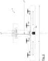
- FIG. 2 shows, again by way of example, an aircraft 10 with a propulsive configuration according to a second embodiment.
- This configuration includes four EM1-EM4 propulsive units mounted, symmetrically with respect to the longitudinal plane of the aircraft 10, on the rear wing of the aircraft equipped with front stabilizers.
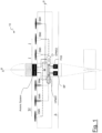
- FIG 3 shows, again by way of example, an aircraft 10 with a propulsive configuration according to a third embodiment.
- This configuration includes eleven propulsive units, one of which is central (EM1), two on the rear stabilizers and eight on the wing (more precisely, for each wing, three with pulling propellers on the leading edge and one with pushing propellers on the trailing edge).
- the aircraft 10 according to the present invention has a full-electric propulsion, with one or more batteries (BP battery pack) that power the propulsive units.
- batteries BP battery pack
- a distributed propulsion aircraft 10 is provided that can simulate, thanks to specifically designed hardware and software, the single-engine SE and multi-engine ME modes. According to the invention, it is therefore possible to train a pilot on board for obtaining (or maintaining) the license to fly both multi-engine aircraft and single-engine aircraft, using an aircraft which is operationally a multi-engine ME, and therefore safer.
- the present invention is based on a logical architecture of hardware and software suitable for carrying out said simulation during flight, and is independent from the number of propulsive units, power generation units PGS, number of EPMS control units that carry out the simulation and from how these are structured and connected. It is also independent of the general configuration of the aircraft.
- a generic electric aircraft should be in any case equipped with a control unit for managing the propulsive unit(s), but such a control unit is dissimilar to the EPMS unit and from what stated before, as this is not specifically designed for simulating the behavior of another kind of aircraft.
- the generic electric aircraft could even have a similar hardware configuration, but the difference is in the control logic and software.
- the propulsive units are managed by a control unit EPMS that allows the pilot to safely fly the aircraft in the desired operating mode.
- a configuration with two propulsive units is sufficient for normal flight, but not in an emergency situation.
- the aircraft 10 would be irremediably conditioned to fly in a skid manner.
- increasing the number of propulsion units EM increases the complexity of the system, but also increases overall safety.
- an electric motor if well cooled, is capable of sustaining a maximum non-continuous power much higher (even 150%) than the nominal one for a few minutes. According to preferred embodiments of the present invention, this property is exploited in an emergency. For example, on an aircraft with four propulsive units in which one is out of order, the remaining three will have to provide 133% of power to have the equivalent total power of the aircraft without malfunctions.
- electric motor non-continuous power could be simulated de-rating them of a certain value, in order to obtain the pursued margin.
- the management of the propulsive units is entirely entrusted to a single control unit.
- a configuration is intrinsically unsafe since, in the event of a single control unit malfunction, there is a total loss of power.
- At least two redundant or cooperating control units are provided which will take charge of all the propulsive units or of a part of them.
- These control units called Energy and Propulsion Management System (EPMS)
- EPMS Energy and Propulsion Management System
- the EPMS control units are preferably configured to manage the discharge and charge of the BP batteries and the mode of use of the PGS system, if present.
- the EPMS control units are configured to communicate with each other and with the on board Avionics Suite both as regards the inputs from the pilot, and for notifications to the pilot and control of the actuators by the autopilot.
- each control unit EPMS is responsible for a certain number of propulsive electric motors, which are in any case arranged so that, in the event of failure or malfunction of one of the two control units EPMS, the yawing moment at the center of mass G generated by them is zero (Equation 1).
- N G EM 0
- the EPMS control units incorporate an inertial platform (IMU, Inertial Measurement Unit) equipped for example with MEMS (Micro Electro-Mechanical Systems), essential to keep the sideslip angle ⁇ at zero when necessary.
- IMU Inertial Measurement Unit
- MEMS Micro Electro-Mechanical Systems
- the information on the sideslip angle could possibly also come from the avionics suite on board, using the inertial platform or the turn rate indicator.
- the EPMS control unit could work with an open-loop or closed-loop control feedback, therefore with a completely analytic motor mapping, as in the scaled demonstrator.
- the propellers are foldable. According to other embodiments, the propellers have variable pitch, so as to be able to minimize the resistance generated in the event of failure of a propulsive unit.
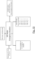
- the control units EPMS are configured to identify a possible failure or malfunction and manage it correctly. Examples of faults or malfunctions can be, for example, one or more of:
- the EPMS control units are configured to detect a failure, apply the appropriate corrective actions and communicate them to the pilot.
- the EPMS units include a Health and Usage Monitoring System (HUMS) for the BP battery pack, the PGS system, the propulsive units EM and the electronic systems, which records the parameters with anomalous values for maintenance purposes.
- HUMS Health and Usage Monitoring System
- the aircraft 10 according to the present invention has an increased safety level since the possibility of a total loss of power is very low if compared to that of a traditional aircraft, especially if single-engine SE. Total loss of power in an aircraft according to the present invention can only occur in the event of multiple failures.
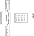
- the pilot has available on the on board display (MFD, Multi-Function Display) the possibility of selecting the SE or ME mode only on the ground before starting taxiing.
- the on board display preferably presents a clear reading of the selected flight mode and, based on this, presents information specially designed to adequately represent the type of aircraft whose simulation is selected.
- the aircraft 10 of the present invention has the ability to choose the best energy management strategy depending on the mission to be flown.
- the aircraft of the invention preferably has two thrust levers, one for each propulsive side, normally locked together. Their position is not directly linked to the revolutions of the electric motors, but to the power required by the driver as a percentage of the total, also providing a segment for the non-continuous power request.
- the system can provide a "Panic Button" that will allow the software to automatically manage the exit from an accidental spin using the differential management of the propulsive units.
- the main piloting difference between an SE aircraft and a ME aircraft is that, in a generic flight condition, an SE aircraft does not achieve a symmetrical balance of forces, due to the yawing moment induced by the rotation of the propeller, which generates a non-zero sideslip angle ⁇ .
- the fuselage or tail of a single-engine aircraft are designed to maintain this angle at zero in the nominal cruising condition, but in other conditions, such as those of application of climb or descent power, this implies that the aircraft flies slightly asymmetric, and the pilot must intervene with an action on the rudder to correct this tendency.
- this characteristic can be simulated by the EPMS control units, for example by acting in a differential manner on the outermost engines (i.e. furthest from the longitudinal plane of the aircraft) to obtain a non-null yawing moment when climb power (or a generic high-power setting) is required, through a non-symmetrical thrust distribution. For example, if the pilot asks for 100% power, an external motor is required less than 100% power (for example 95%) while the others will operate at 100% power. In descent, the EPMS control units will ensure that only some propellers do close (or pitch-feather), leaving one or more open in order to generate a non-symmetrical drag distribution.
- a further desirable feature of the system is that of simulating the turn response of a single-engine aircraft: propeller effects induce a different right or left turning behavior. This could be reproduced with a differential power distribution on the right or left side.
- the operating mode of a traditional thermal engine can be simulated, for instance an internal combustion reciprocating engine, or a turbofan or turboprop engine, by introducing delays, irregularities and other features in the delivery of power via software and the decrease of power with the increase in altitude (which does not happen with an electric motor).
- This latter feature is independent from the selected SE or ME mode, and can be exploited in both.
- the two thrust levers are locked together all the time and in the event of an inadvertent differential setting the system will consider the greatest of the two.
- the aircraft of the present invention is configured in such a way as to prevent a Pilot in Command (PIC) or a student (SPIC) with SE qualification from being able to enter a non-symmetrical thrust condition. Consequently, the following scenarios are taken into account:
- the thrust levers can be unlocked and used independently from each other for training or other purposes: the pilot has complete authority over the dynamics of the aircraft.
- An ME qualified pilot must be able to handle an asymmetrical thrust situation caused by an engine failure.
- the ability to reduce a pilot's workload always has a positive impact. Consequently, according to the present invention, the same emergency strategy is adopted as in SE mode, unless the pilot decides to bypass it.
- An optional operating mode for both SE and ME configurations is to simulate the behavior of a jet engine using the EPMS control unit software. This implies in the first place a delay in the delivery of power as occurs in jet engines (spool-up time), forcing the student to make approaches at high rotational speeds, showing parameters of the dummy engines, appropriately defined, on the PFD (Primary Flight Display) and allowing to simulate the airbrakes with the differential (but symmetrical) use of some engines, up to the limit of reversing the direction of rotation, and the thrust reversers once on the ground.
- PFD Primary Flight Display
- the flight instructor sits next to the student on many flights. Thanks to the present invention, it will be able to inject faults and malfunctions through the MFD (Multi Function Display) within the avionics and propulsion systems to better train students to take the best action.
- MFD Multi Function Display
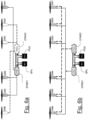
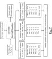
- Figures 6a and 6b show the operating diagrams of two control units EPMS1 and EPMS2 in a cooperating and redundant configuration, respectively in the case, merely by way of example, of an aircraft with six propulsive units EM1-EM6.
- the first control unit EPMS1 is connected to the outermost propulsive unit EM1 of the right half-wing as well as to the central propulsive unit EM5 and the internal propulsive unit EM4 of the left half-wing.
- the second control unit EPMS2 is connected to the external propulsive unit EM6 of the left half-wing as well as to the central propulsive unit EM2 and the internal propulsive unit EM3 of the right half-wing.
- the propulsive units may lie at an equal distance from each other or not, according to design optimization.
- the internal propulsion units EM3, EM4 (i.e. closer to the fuselage) are at a distance l from the longitudinal plane of the aircraft 10.
- Each control unit EPMS is connected to the other control unit, as well as to the battery pack BP and the PGS system.
- each control unit EPMS1 EPMS2 is connected to all the motors EM1-EM6.
- each control unit is connected to the other control unit, as well as to the battery pack BP and the PGS system.
- control units can interface with each other and with the propulsive units EM according to one of the two aforesaid configurations or in other ways, depending on the choice made by the aircraft manufacturer and on other imposed parameters.
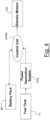
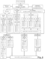
- a schematic example of how the single control unit EPMS1 is connected to the other systems is in Figure 5 . The same applies to the second control unit EPMS2.
- Figure 11 shows, by way of example, a possible logic feedback scheme for the operation of the generic control unit EPMS.
- a reference input ( ⁇ 0 ; ⁇ 0 ) (with ⁇ indicating the bank angle) dependent on the operating mode in use and on the specific flight situation, this is compared and fed back with the measured values of the sideslip angle and bank angle ( ⁇ M ; ⁇ M ) coming from the inertial measurement unit IMU.
- the control unit software will act to cancel the error between reference angles and measured angles, depending on whether this is contained within a certain tolerance range or not.
- This range of values will be a function of the aerodynamic, inertial and propulsive parameters of the aircraft, as well as the current state of health of the electric motors.
- the instantaneous state of health of electric motors can be obtained, for example, through the temperature value of the single motor and the electric current required by each, which can be compared with tabulated values, functions of number of revolutions and applied voltage.
- the absorbed current differs greatly from the nominal one, this could be an indication that the motor or the propeller has suffered a failure: for example, with a damaged propeller the electric current values would be much lower than the nominal ones, while with a blocked motor these would be much higher.
- Two scenarios are therefore possible:
- the adjustment of the individual engines, as well as that of the control surfaces, will in any case be the result of an interaction between the control imposed by the pilot and the programming of the control unit.
- the latter must therefore know the instantaneous position of the control surfaces to avoid interference or any unwanted phenomena.
- the preferential logic provides that, as for many autopilots, for a limited action by the pilot on the controls, this latter effect is added algebraically with the action imposed on them by the EPMS, while for a drive that involves high deflection angles the pilot is in control.
- the control unit included in the EPMS can be a controller designed with PID, LQR or other feedback technique.
- the present invention is adaptable to different types of aircraft, in different configurations.
- Figures 1-3 show three of the large amounts of possible combinations.
- Figure 1 shows an aircraft in a conventional configuration with a serial Hybrid-electric propulsion architecture. It has a total of six electric motors in pulling configuration, uniformly positioned on the wing, three for each wing, two collaborating control units EPMS1 and EPMS2, a battery pack BP and a power generation system PGS for charging the battery pack BP.
- EPMS1 and EPMS2 two collaborating control units
- BP battery pack
- PGS power generation system
- Figure 2 shows an electric "Canard" configuration, with four motors positioned on the wing, a single control unit EPMS and a battery pack.
- the configuration with a single unit EPMS is still able to guarantee every characteristic described above.
- the obvious disadvantage is the total loss of power in the event of a failure of the control unit involved, given the absence of a second one; however, this configuration could be exploited, for example, on small aircraft.
- Figure 3 shows a third possible configuration: an electric aircraft with a total of three collaborating control units EPMS and eleven propulsive units. Also in this case, following the failure of one or even two control units EPMS, a yawing moment equal to zero is guaranteed thanks to the arrangement of the propulsive units and their connections to the control units. In case of failure of one or more units, the symmetrical flight will be guaranteed as already described. Particularly of note in this configuration is the odd number of propulsive units: in fact, one (EM1) is located in the nose of the aircraft and has a different size than the others.
- EM1 is located in the nose of the aircraft and has a different size than the others.
- Table 2 shows some characteristic operating points.
- Table 2 VCAS flight speed 52 m/s 52 m/s 35 m/s 65 m/s Throttle unbalance 10% 25% 10% 10% Angle of incidence ⁇ 4.38 deg 4.38 deg 11.55 deg 2.25 deg Sideslip angle ⁇ 0.74 deg 1.86 deg 1.83 deg 0.42 deg Rudder deflection ⁇ R -0.98 deg -2.46 deg -2.42 deg -0.56 deg Aileron deflection ⁇ A -0.06 deg -0.17 deg -0.16 deg -0.04 deg
- the values are a function of the flight speed, therefore also of the force exerted by the single propeller, and of the stability and control derivatives of the aircraft.
- the unbalance for the creation of the yawing moment can be implemented both by acting on a single motor (for example 10% less power on motor EM1), and on two (-5% on motor 1, + 5% on motor EM6). The last mode allows to preserve the total available power unchanged.
- the sideslip angle induced with the SE aircraft simulation strongly depends on the flight speed: in fact, maintaining an unbalance of 10%, at low speed the sideslip angle is greater than at high speed.
- This behavior perfectly reflects that of a real single-engine aircraft.
- the induced bank angle (and therefore the consequent necessary deflection of the ailerons) is an order of magnitude lower than the variation of azimuth angle, also in this case reflecting the dynamics of a real aircraft.
- the longitudinal dynamic of the aircraft is unaltered, as long as the power supplied is constant.
- ⁇ T refers to the throttle setting when the two control levers are joined, while ⁇ T1 and ⁇ T2 refer to the setting of the left and right thrust levers.
Landscapes
- Engineering & Computer Science (AREA)
- Aviation & Aerospace Engineering (AREA)
- Mechanical Engineering (AREA)
- Theoretical Computer Science (AREA)
- Business, Economics & Management (AREA)
- Physics & Mathematics (AREA)
- Educational Administration (AREA)
- Educational Technology (AREA)
- General Physics & Mathematics (AREA)
- Feedback Control In General (AREA)
Claims (19)
- Starrflügelflugzeug (10) mit verteiltem elektrischen Antrieb, das eine Vielzahl von elektrischen Antriebseinheiten (EM1-EM6; EM1-EM4; EM1-EM11) und eine Längsebene aufweist,wobei die elektrischen Antriebseinheiten (EM1-EM6; EM1-EM4; EM1-EM11) symmetrisch in Bezug auf die Längsebene angeordnet sind,wobei die elektrischen Antriebseinheiten (EM1-EM6; EM1-EM4) erste Antriebseinheiten an einer ersten Seite der Längsebene und zweite Antriebseinheiten an einer zweiten Seite der Längsebene umfassen,wobei das Flugzeug (10) mit verteiltem Antrieb ferner eine Steuereinheit (EPMS) umfasst, die so konfiguriert ist, dass sie ein Giermoment bereitstellt, so dass ein Schiebewinkel β erzeugt wird, so dass das Flugzeug (10) mit verteiltem elektrischen Antrieb wie ein Starrflügler fliegt, der mit einem einzelnen Propeller ausgestattet ist,wobei die Steuereinheit (EPMS) so konfiguriert ist, dass sie den Betriebsmodus eines herkömmlichen thermischen Triebwerks oder eines Turbofan- oder Turboprop-Triebwerks simuliert, indem sie eine Verzögerung und/oder eine Unregelmäßigkeit in der Leistungsabgabe einführt und/oder indem sie die Leistung mit der Zunahme der Höhe verringert.
- Starrflügelflugzeug (10) mit verteiltem elektrischen Antrieb nach Anspruch 1, wobei das Giermoment dadurch erzeugt wird, dass eine unterschiedliche Leistung zwischen mindestens einer der ersten Antriebseinheiten und einer entsprechenden mindestens einen der zweiten Antriebseinheiten bewirkt wird.
- Starrflügelflugzeug (10) mit verteiltem elektrischen Antrieb nach Anspruch 1 oder 2, wobei mindestens eine der ersten Antriebseinheiten Folgendes umfasst mindestens eine der ersten Antriebseinheiten einen ersten Faltpropeller umfasst und mindestens eine der zweiten Antriebseinheiten einen zweiten Faltpropeller umfasst, und wobei das Giermoment erzeugt wird, indem ein unterschiedliches Schließen zwischen dem ersten Faltpropeller und dem zweiten Faltpropeller bewirkt wird.
- Starrflügelflugzeug (10) mit verteiltem elektrischem Antrieb nach Anspruch 1, 2 oder 3, wobei mindestens eine der ersten Antriebseinheiten einen ersten Verstellpropeller umfasst und mindestens eine der zweiten Antriebseinheiten einen zweiten Verstellpropeller umfasst, und wobei das Giermoment erzeugt wird, indem eine unterschiedliche Steigung zwischen dem ersten Verstellpropeller und dem zweiten Verstellpropeller bewirkt wird.
- Starrflügelflugzeug (10) mit verteiltem elektrischem Antrieb nach einem der vorhergehenden Ansprüche, wobei die Steuereinheit (EPMS) so konfiguriert ist, dass sie im Falle eines Ausfalls einer Antriebseinheit oder im Falle einer Kollision mit einem externen Objekt die Leistung der ersten Antriebseinheit reduziert und/oder die Leistung der zweiten Antriebseinheit erhöht, um den Schiebewinkel β im Wesentlichen gleich Null zu halten.
- Starrflügelflugzeug (10) mit verteiltem elektrischem Antrieb nach einem der vorhergehenden Ansprüche, das außerdem ein Batteriepaket (BP) und optional ein Energieerzeugungssystem (PGS) zum Laden des Batteriepakets umfasst.
- Starrflügelflugzeug (10) mit verteiltem elektrischem Antrieb nach einem der vorhergehenden Ansprüche, das außerdem eine Trägheitsmesseinheit (IMU) umfasst, die mit der Steuereinheit (EPMS) zusammenarbeitet.
- Starrflügelflugzeug (10) mit verteiltem elektrischem Antrieb nach einem der vorhergehenden Ansprüche, das so konfiguriert ist, dass es einen Piloten an Bord für das Fliegen mit einem Starrflügelflugzeug ausbildet, das mit einem einzelnen Propeller ausgestattet ist, wie z.B. in einem einmotorigen Flugzeug, während der Pilot mit dem Starrflügelflugzeug (10) mit verteiltem elektrischem Antrieb fliegt.
- Starrflügelflugzeug (10) mit verteiltem elektrischem Antrieb nach einem der vorhergehenden Ansprüche, das zwei Steuereinheiten (EPMS1, EPMS2) in einer zusammenwirkenden Konfiguration umfasst, wobei eine erste Steuereinheit (EPMS1) mit einer ersten Gruppe von Antriebseinheiten (EM1, EM4, EM5) verbunden ist und eine zweite Steuereinheit (EPMS2) mit einer zweiten Gruppe von Antriebseinheiten (EM2, EM3, EM6) verbunden ist und wobei die erste und die zweite Steuereinheit (EPMS1, EPMS2) miteinander verbunden sind.
- Starrflügelflugzeug (10) mit verteiltem elektrischem Antrieb nach einem der Ansprüche 1 bis 8, das zwei Steuereinheiten (EPMS1, EPMS2) in einer redundanten Konfiguration umfasst, wobei eine erste Steuereinheit (EPMS1) mit allen Antriebseinheiten (EM1-EM6) verbunden ist und die zweite Steuereinheit (EPMS2) mit allen Antriebseinheiten (EM1-EM6) verbunden ist und wobei die erste und die zweite Steuereinheit (EPMS1, EPMS2) miteinander verbunden sind.
- Starrflügelflugzeug (10) mit verteiltem elektrischem Antrieb nach einem der vorhergehenden Ansprüche, wobei die Steuereinheit (EPMS) so konfiguriert ist, dass sie aus einem unbeabsichtigten Trudeln unter Verwendung einer Differenzsteuerung der Antriebseinheiten nach Auswahl einer geeigneten Option durch einen Piloten an Bord aussteigt.
- Starrflügelflugzeug (10) mit verteiltem elektrischem Antrieb nach einem der vorhergehenden Ansprüche, wobei die Steuereinheit (EPMS) so konfiguriert ist, dass sie ein Kurvenverhalten eines einmotorigen Flugzeugs durch eine Leistungsdifferenz zwischen mindestens einer der ersten Antriebseinheiten und mindestens einer der zweiten Antriebseinheiten simuliert.
- Verfahren zum Betreiben eines Starrflügelflugzeugs (10) mit verteiltem elektrischem Antrieb, so dass das Starrflügelflugzeug (10) mit verteiltem Antrieb wie ein Starrflügelflugzeug mit einer einzigen Antriebseinheit fliegt,wobei das Flugzeug (10) mit verteiltem elektrischem Antrieb eine Vielzahl von elektrischen Antriebseinheiten (EM1-EM6; EM1-EM4; EM1-EM11) und eine Längsebene umfasst,wobei die elektrischen Antriebseinheiten (EM1-EM6; EM1-EM4; EM1-EM11) symmetrisch in Bezug auf die Längsebene angeordnet sind,wobei die elektrischen Antriebseinheiten (EM1-EM6; EM1-EM4) erste Antriebseinheiten an einer ersten Seite der Längsebene und zweite Antriebseinheiten an einer zweiten Seite der Längsebene aufweisen,wobei das Flugzeug (10) mit verteiltem elektrischen Antrieb ferner eine Steuereinheit (EPMS) umfasst,wobei das Verfahren das Bereitstellen eines Giermoments umfasst, so dass ein Schiebewinkel β erzeugt wird,wobei die Steuereinheit (EPMS) so konfiguriert ist, dass sie den Betriebsmodus eines herkömmlichen thermischen Triebwerks oder eines Turbofan- oder Turboprop-Triebwerks simuliert, indem sie eine Verzögerung und/oder eine Unregelmäßigkeit in der Leistungsabgabe einführt und/oder indem sie die Leistung mit der Zunahme der Höhe verringert.
- Verfahren nach Anspruch 13, wobei das Giermoment dadurch erzeugt wird, dass eine unterschiedliche Leistung zwischen mindestens einer der ersten Antriebseinheiten und einer entsprechenden mindestens einen der zweiten Antriebseinheiten bewirkt wird.
- Verfahren nach Anspruch 13 oder 14, wobei mindestens eine der ersten Antriebseinheiten einen ersten Faltpropeller umfasst und mindestens eine der zweiten Antriebseinheiten einen zweiten Faltpropeller umfasst, und wobei das Giermoment erzeugt wird, indem ein unterschiedliches Schließen zwischen dem ersten Faltpropeller und dem zweiten Faltpropeller bewirkt wird.
- Verfahren nach Anspruch 13, 14 oder 15, wobei mindestens eine der ersten Antriebseinheiten einen ersten Verstellpropeller umfasst und mindestens eine der zweiten Antriebseinheiten einen zweiten Verstellpropeller umfasst, und wobei das Giermoment erzeugt wird, indem eine unterschiedliche Steigung zwischen dem ersten Verstellpropeller und dem zweiten Verstellpropeller bewirkt wird.
- Verfahren nach einem der vorhergehenden Ansprüche 13-16, wobei im Falle eines Ausfalls einer Antriebseinheit oder im Falle einer Kollision mit einem externen Objekt die Leistung der ersten Antriebseinheit reduziert und/oder die Leistung der zweiten Antriebseinheit erhöht wird, um den Schwimmwinkel β im Wesentlichen gleich Null zu halten.
- Verfahren nach einem der vorhergehenden Ansprüche 13-17, wobei das Starrflügelflugzeug (10) mit verteiltem elektrischem Antrieb betrieben wird, um einen Piloten an Bord desselben zu trainieren, mit einem Starrflügelflugzeug zu fliegen, das mit einem einzelnen Propeller ausgestattet ist, wie beispielsweise in einem einmotorigen Flugzeug, während der Pilot mit dem Starrflügelflugzeug (10) mit verteiltem elektrischem Antrieb fliegt.
- Verfahren nach einem der vorhergehenden Ansprüche 13-18, wobei die Steuereinheit (EPMS) so konfiguriert ist, dass sie: ein unbeabsichtigtes Trudeln unter Verwendung einer Differenzsteuerung der Antriebseinheiten nach Auswahl einer geeigneten Option durch einen Piloten an Bord zu verlassen; und/oder ein Kurvenverhalten eines einmotorigen Flugzeugs durch eine Leistungsdifferenz zwischen mindestens einer der ersten Antriebseinheiten und mindestens einer der zweiten Antriebseinheiten zu simulieren; und/oder den Betriebsmodus eines herkömmlichen thermischen Triebwerks oder eines Turbofan- oder Turboprop-Triebwerks zu simulieren, indem eine Verzögerung und/oder eine Unregelmäßigkeit bei der Leistungsabgabe eingeführt wird und/oder indem die Leistung mit der Zunahme der Höhe abnimmt.
Applications Claiming Priority (2)
| Application Number | Priority Date | Filing Date | Title |
|---|---|---|---|
| IT102020000010369A IT202000010369A1 (it) | 2020-05-08 | 2020-05-08 | Velivolo plurimotore simulante un monomotore via hardware e software |
| PCT/EP2021/062217 WO2021224490A1 (en) | 2020-05-08 | 2021-05-07 | Distributed electric propulsion aircraft simulating a single propeller aircraft |
Publications (3)
| Publication Number | Publication Date |
|---|---|
| EP4146544A1 EP4146544A1 (de) | 2023-03-15 |
| EP4146544B1 true EP4146544B1 (de) | 2024-12-11 |
| EP4146544C0 EP4146544C0 (de) | 2024-12-11 |
Family
ID=71784492
Family Applications (1)
| Application Number | Title | Priority Date | Filing Date |
|---|---|---|---|
| EP21725107.3A Active EP4146544B1 (de) | 2020-05-08 | 2021-05-07 | Flugzeug mit verteiltem elektrischen antrieb, das ein flugzeug mit einem einzigen propeller simuliert |
Country Status (3)
| Country | Link |
|---|---|
| EP (1) | EP4146544B1 (de) |
| IT (1) | IT202000010369A1 (de) |
| WO (1) | WO2021224490A1 (de) |
Families Citing this family (5)
| Publication number | Priority date | Publication date | Assignee | Title |
|---|---|---|---|---|
| DE102021106648A1 (de) * | 2021-03-18 | 2022-09-22 | Rolls-Royce Deutschland Ltd & Co Kg | System und Verfahren zur Simulation unterschiedlicher Luftfahrzeugkonfigurationen mit einem Elektroflugzeug |
| WO2023122111A1 (en) * | 2021-12-23 | 2023-06-29 | Electra Aero, Inc. | System and method for controlling flight path of a blown lift aircraft |
| US12384550B2 (en) | 2021-12-23 | 2025-08-12 | Electra Aero, Inc. | System and method for controlling flight path of a blown lift aircraft |
| CN115571353B (zh) * | 2022-12-07 | 2023-03-17 | 中国航空工业集团公司沈阳飞机设计研究所 | 一种飞机上分布式油箱 |
| CN117058947B (zh) * | 2023-09-12 | 2024-03-15 | 广州天海翔航空科技有限公司 | 一种固定翼无人机半仿真飞行训练系统及方法 |
Family Cites Families (10)
| Publication number | Priority date | Publication date | Assignee | Title |
|---|---|---|---|---|
| US6917908B2 (en) * | 2001-03-16 | 2005-07-12 | Bell Helicopter Textron Inc. | Method of pilot training using simulated engine failure |
| FR2946015B1 (fr) | 2009-06-02 | 2011-07-15 | Airbus France | Systeme de gestion automatique de modes de controle de moteurs d'un aeronef multimoteur. |
| ES2545994T3 (es) | 2011-04-28 | 2015-09-17 | The Boeing Company | Programa de límite de empuje modificado para el control de la asimetría de empuje |
| EP2903895B1 (de) * | 2012-10-05 | 2020-01-22 | Skykar Inc. | Elektrisch angetriebene luftfahrzeuge und flugsteuerungsverfahren |
| US10124890B2 (en) * | 2014-04-11 | 2018-11-13 | Dronetechuav Corporation | Modular nacelles to provide vertical takeoff and landing (VTOL) capabilities to fixed wing aerial vehicles, and associated systems and methods |
| US9751614B1 (en) * | 2015-02-20 | 2017-09-05 | The United States Of America As Represented By The Administrator Of Nasa | Aeroelastic wing shaping using distributed propulsion |
| US10384774B2 (en) * | 2016-09-08 | 2019-08-20 | General Electric Company | Tiltrotor propulsion system for an aircraft |
| FR3065443B1 (fr) | 2017-04-19 | 2021-01-01 | Airbus Group Sas | Methode pour la gestion de la dissymetrie au sein d’un systeme de propulsion distribuee |
| WO2019006469A1 (en) * | 2017-06-30 | 2019-01-03 | A3 By Airbus, Llc | FAULT TOLERANT ELECTRICAL SYSTEMS FOR AIRCRAFT |
| US11480980B2 (en) * | 2018-09-19 | 2022-10-25 | Rosemount Aerospace Inc. | Aircraft anti-spin systems |
-
2020
- 2020-05-08 IT IT102020000010369A patent/IT202000010369A1/it unknown
-
2021
- 2021-05-07 EP EP21725107.3A patent/EP4146544B1/de active Active
- 2021-05-07 WO PCT/EP2021/062217 patent/WO2021224490A1/en not_active Ceased
Also Published As
| Publication number | Publication date |
|---|---|
| EP4146544A1 (de) | 2023-03-15 |
| IT202000010369A1 (it) | 2021-11-08 |
| EP4146544C0 (de) | 2024-12-11 |
| WO2021224490A1 (en) | 2021-11-11 |
Similar Documents
| Publication | Publication Date | Title |
|---|---|---|
| EP4146544B1 (de) | Flugzeug mit verteiltem elektrischen antrieb, das ein flugzeug mit einem einzigen propeller simuliert | |
| US20240190565A1 (en) | Fail-operational vtol aircraft | |
| CN108725803B (zh) | 管理分布式推进系统中不平衡的方法 | |
| Muraoka et al. | Transition flight of quad tilt wing VTOL UAV | |
| EP3761145B1 (de) | Flugzeugsteuerungsverfahren | |
| US11465738B2 (en) | Fail-operational VTOL aircraft | |
| US20240124134A1 (en) | Electric vtol aircraft with tilting propellers and lifting propellers | |
| US20240400213A1 (en) | Systems and methods for flight control of aircraft | |
| US20140302461A1 (en) | Method of driving a main rotor of a rotorcraft in the context of simulating a failure of one of the engines of the rotorcraft | |
| Chakraborty et al. | Development of a modeling, flight simulation, and control analysis capability for novel vehicle configurations | |
| US20170025032A1 (en) | Method of driving a main rotor of a rotorcraft in the context of simulating a failure of one of the engnes of the rotorcraft | |
| Courtin | An assessment of electric STOL aircraft | |
| Borer et al. | Distributed thrust takeoff for the NASA X-57 Mod IV flight demonstrator | |
| Trainelli et al. | Distributed Electric Propulsion Aircraft Simulating a Single Propeller Aircraft | |
| McCuish et al. | Development and flight experience of the control laws and the aeroservoelastic solution in the Experimental Aircraft Programme (EAP) | |
| Fielding et al. | Industrial considerations for flight control | |
| Wallace et al. | Development of the X-57 Mod III/IV piloted simulator and discussion of the resultant flying qualities predictions | |
| Benyamen et al. | Flight test validation verification of@ AIR distributed electric propulsion aircraft dynamic model | |
| Nye-Matthew et al. | Modelling, design and control of middle-size tilt-rotor quadrotor | |
| Reynolds | X-57 flight controls lessons learned | |
| Braggett et al. | Feasibility of Electric Ducted Fans to replace open propellers on an electrified training aircraft | |
| Bosworth et al. | The x-31a quasi-tailless flight test results | |
| Marr et al. | Handling Qualities Evaluation of the XV‐15 Tilt Rotor Aircraft | |
| Dunford et al. | The V-22 Osprey: A significant flight test challenge | |
| Borer et al. | X-57 Flight Performance and Failure Considerations |
Legal Events
| Date | Code | Title | Description |
|---|---|---|---|
| STAA | Information on the status of an ep patent application or granted ep patent |
Free format text: STATUS: UNKNOWN |
|
| STAA | Information on the status of an ep patent application or granted ep patent |
Free format text: STATUS: THE INTERNATIONAL PUBLICATION HAS BEEN MADE |
|
| PUAI | Public reference made under article 153(3) epc to a published international application that has entered the european phase |
Free format text: ORIGINAL CODE: 0009012 |
|
| STAA | Information on the status of an ep patent application or granted ep patent |
Free format text: STATUS: REQUEST FOR EXAMINATION WAS MADE |
|
| 17P | Request for examination filed |
Effective date: 20221205 |
|
| AK | Designated contracting states |
Kind code of ref document: A1 Designated state(s): AL AT BE BG CH CY CZ DE DK EE ES FI FR GB GR HR HU IE IS IT LI LT LU LV MC MK MT NL NO PL PT RO RS SE SI SK SM TR |
|
| DAV | Request for validation of the european patent (deleted) | ||
| DAX | Request for extension of the european patent (deleted) | ||
| GRAP | Despatch of communication of intention to grant a patent |
Free format text: ORIGINAL CODE: EPIDOSNIGR1 |
|
| STAA | Information on the status of an ep patent application or granted ep patent |
Free format text: STATUS: GRANT OF PATENT IS INTENDED |
|
| INTG | Intention to grant announced |
Effective date: 20240712 |
|
| GRAS | Grant fee paid |
Free format text: ORIGINAL CODE: EPIDOSNIGR3 |
|
| GRAA | (expected) grant |
Free format text: ORIGINAL CODE: 0009210 |
|
| STAA | Information on the status of an ep patent application or granted ep patent |
Free format text: STATUS: THE PATENT HAS BEEN GRANTED |
|
| AK | Designated contracting states |
Kind code of ref document: B1 Designated state(s): AL AT BE BG CH CY CZ DE DK EE ES FI FR GB GR HR HU IE IS IT LI LT LU LV MC MK MT NL NO PL PT RO RS SE SI SK SM TR |
|
| REG | Reference to a national code |
Ref country code: GB Ref legal event code: FG4D |
|
| REG | Reference to a national code |
Ref country code: CH Ref legal event code: EP |
|
| REG | Reference to a national code |
Ref country code: DE Ref legal event code: R096 Ref document number: 602021023266 Country of ref document: DE |
|
| REG | Reference to a national code |
Ref country code: IE Ref legal event code: FG4D |
|
| U01 | Request for unitary effect filed |
Effective date: 20250109 |
|
| U07 | Unitary effect registered |
Designated state(s): AT BE BG DE DK EE FI FR IT LT LU LV MT NL PT RO SE SI Effective date: 20250116 |
|
| PG25 | Lapsed in a contracting state [announced via postgrant information from national office to epo] |
Ref country code: HR Free format text: LAPSE BECAUSE OF FAILURE TO SUBMIT A TRANSLATION OF THE DESCRIPTION OR TO PAY THE FEE WITHIN THE PRESCRIBED TIME-LIMIT Effective date: 20241211 |
|
| PG25 | Lapsed in a contracting state [announced via postgrant information from national office to epo] |
Ref country code: ES Free format text: LAPSE BECAUSE OF FAILURE TO SUBMIT A TRANSLATION OF THE DESCRIPTION OR TO PAY THE FEE WITHIN THE PRESCRIBED TIME-LIMIT Effective date: 20241211 |
|
| PG25 | Lapsed in a contracting state [announced via postgrant information from national office to epo] |
Ref country code: NO Free format text: LAPSE BECAUSE OF FAILURE TO SUBMIT A TRANSLATION OF THE DESCRIPTION OR TO PAY THE FEE WITHIN THE PRESCRIBED TIME-LIMIT Effective date: 20250311 |
|
| PG25 | Lapsed in a contracting state [announced via postgrant information from national office to epo] |
Ref country code: GR Free format text: LAPSE BECAUSE OF FAILURE TO SUBMIT A TRANSLATION OF THE DESCRIPTION OR TO PAY THE FEE WITHIN THE PRESCRIBED TIME-LIMIT Effective date: 20250312 |
|
| PG25 | Lapsed in a contracting state [announced via postgrant information from national office to epo] |
Ref country code: RS Free format text: LAPSE BECAUSE OF FAILURE TO SUBMIT A TRANSLATION OF THE DESCRIPTION OR TO PAY THE FEE WITHIN THE PRESCRIBED TIME-LIMIT Effective date: 20250311 |
|
| U20 | Renewal fee for the european patent with unitary effect paid |
Year of fee payment: 5 Effective date: 20250528 |
|
| PG25 | Lapsed in a contracting state [announced via postgrant information from national office to epo] |
Ref country code: SM Free format text: LAPSE BECAUSE OF FAILURE TO SUBMIT A TRANSLATION OF THE DESCRIPTION OR TO PAY THE FEE WITHIN THE PRESCRIBED TIME-LIMIT Effective date: 20241211 |
|
| PG25 | Lapsed in a contracting state [announced via postgrant information from national office to epo] |
Ref country code: PL Free format text: LAPSE BECAUSE OF FAILURE TO SUBMIT A TRANSLATION OF THE DESCRIPTION OR TO PAY THE FEE WITHIN THE PRESCRIBED TIME-LIMIT Effective date: 20241211 |
|
| PG25 | Lapsed in a contracting state [announced via postgrant information from national office to epo] |
Ref country code: IS Free format text: LAPSE BECAUSE OF FAILURE TO SUBMIT A TRANSLATION OF THE DESCRIPTION OR TO PAY THE FEE WITHIN THE PRESCRIBED TIME-LIMIT Effective date: 20250411 |
|
| PG25 | Lapsed in a contracting state [announced via postgrant information from national office to epo] |
Ref country code: SK Free format text: LAPSE BECAUSE OF FAILURE TO SUBMIT A TRANSLATION OF THE DESCRIPTION OR TO PAY THE FEE WITHIN THE PRESCRIBED TIME-LIMIT Effective date: 20241211 |
|
| PG25 | Lapsed in a contracting state [announced via postgrant information from national office to epo] |
Ref country code: CZ Free format text: LAPSE BECAUSE OF FAILURE TO SUBMIT A TRANSLATION OF THE DESCRIPTION OR TO PAY THE FEE WITHIN THE PRESCRIBED TIME-LIMIT Effective date: 20241211 |
|
| PLBE | No opposition filed within time limit |
Free format text: ORIGINAL CODE: 0009261 |
|
| STAA | Information on the status of an ep patent application or granted ep patent |
Free format text: STATUS: NO OPPOSITION FILED WITHIN TIME LIMIT |
|
| REG | Reference to a national code |
Ref country code: CH Ref legal event code: L10 Free format text: ST27 STATUS EVENT CODE: U-0-0-L10-L00 (AS PROVIDED BY THE NATIONAL OFFICE) Effective date: 20251022 |
|
| 26N | No opposition filed |
Effective date: 20250912 |
|
| REG | Reference to a national code |
Ref country code: CH Ref legal event code: H13 Free format text: ST27 STATUS EVENT CODE: U-0-0-H10-H13 (AS PROVIDED BY THE NATIONAL OFFICE) Effective date: 20251223 |
|
| PG25 | Lapsed in a contracting state [announced via postgrant information from national office to epo] |
Ref country code: CH Free format text: LAPSE BECAUSE OF NON-PAYMENT OF DUE FEES Effective date: 20250531 |
|
| GBPC | Gb: european patent ceased through non-payment of renewal fee |
Effective date: 20250507 |
|
| PG25 | Lapsed in a contracting state [announced via postgrant information from national office to epo] |
Ref country code: MC Free format text: LAPSE BECAUSE OF FAILURE TO SUBMIT A TRANSLATION OF THE DESCRIPTION OR TO PAY THE FEE WITHIN THE PRESCRIBED TIME-LIMIT Effective date: 20241211 |